
 Open Access Article
 This Open Access Article is licensed under a Creative Commons Attribution-Non Commercial 3.0 Unported Licence
Iron-based energy storage materials from carbon dioxide and scrap metal†
Joyce S.
Yeoh
 a,
Iolanda
Di Bernardo
bc,
Nicholas G.
White
d,
Vincent
Otieno-Alego
e,
Takuya
Tsuzuki
a and
Adrian
Lowe
*a
a,
Iolanda
Di Bernardo
bc,
Nicholas G.
White
d,
Vincent
Otieno-Alego
e,
Takuya
Tsuzuki
a and
Adrian
Lowe
*a
aResearch School of Electrical, Energy and Materials Engineering, The Australian National University, Canberra, ACT 2601, Australia. E-mail: adrian.lowe@anu.edu.au; Tel: +61 2 6125 4881
bSchool of Physics and Astronomy, Monash University, Clayton, VIC, Australia
cARC Centre for Future Low Energy Electronics Technologies, Monash University, Clayton, VIC, Australia
dResearch School of Chemistry, The Australian National University, Canberra, ACT 2601, Australia
eSpecialist Operations, Australian Federal Police, Canberra, ACT 2609, Australia
First published on 11th November 2020
Abstract
The need for sustainable energy storage materials is extremely relevant today, given the increase in demand for energy storage and net zero carbon commitments made recently by multiple countries. In this study, scrap mild steel and carbon dioxide were utilised to synthesise ferrous oxalates, and the feasibility of using ferrous oxalate to store energy and carbon was investigated. Since transition metal oxalates are commonly used as precursors to oxides in the context of energy storage materials, the properties and performance of anhydrous ferrous oxalate were compared with those of iron oxides synthesised from ferrous oxalate. Hydrated ferrous oxalate was synthesised electrochemically from carbon dioxide and scrap mild steel. Subsequent heat treatment of the hydrated material at different temperatures, in both N2 and air, produced anhydrous ferrous oxalate and iron oxides. The products were characterised, carbon content analysed, and their electrochemical performances as negative electrode materials in lithium-ion batteries were investigated. Results indicated that anhydrous ferrous oxalate exhibited the highest gravimetric discharge capacities (810 mA h g−1), and the highest carbon content (0.28 g A h−1) when cycled at 100 mA g−1. Although the carbon content is low relative to graphite, this study demonstrates that there may be value in further investigating transition metal oxalates as sustainable energy storage materials.
Introduction
The increasing energy demand and the shift towards more intermittent renewable energy sources are currently driving the development of sustainable energy storage materials. While improving the performance of energy storage materials is essential, it is necessary to consider sustainability and environmental impact at all points of their life cycle.1 With the increase in momentum towards decarbonising technology and circular economies, it is especially attractive to explore new methods to synthesise materials from waste, using them to store carbon and reducing their carbon footprints.Lithium-ion batteries (LIBs) are a form of commercially available energy storage, although research into developing higher performing and more sustainable materials for them is still ongoing.2 Transition metal oxides have received significant amounts of attention as LIB negative electrode materials due to higher theoretical capacities (e.g. ∼1000 mA h g−1 for Fe2O3) compared to conventional graphite (372 mA h g−1). Transition metal oxides (MxO) are classified as conversion-type materials, where their energy storage mechanism involves the formation of elemental metal (M) and Li2O (eqn (1)):3
| MxO + 2yLi → xM + yLi2O | (1) |
One method of synthesising transition metal oxides is to decompose transition metal oxalates (TMOxs) thermally. The appeal in using TMOxs as precursors stems from the ability to obtain transition metal oxides that are nanostructured and porous. These types of morphology facilitate the effective contact between electrolyte and the internal active material, leading to rapid Li+ transportation.4 The nanostructures and pores are formed as the oxalate anion (C2O42−) decomposes into gaseous CO and CO2.5–8 Incomplete decomposition of TMOxs under certain environments has been shown to yield oxides with carbon residue, leading to better electrochemical performances compared to oxides prepared via complete decomposition in a more oxidative environment.9,10 TMOxs are often synthesised in the hydrated form. Considering that reactions between water and the lithium electrolyte can be detrimental to the electrochemical performance, TMOxs that are used directly as energy storage materials are typically heat-treated to obtain their anhydrous form.11
The direct application of TMOxs as energy storage materials has been investigated to a lesser extent than oxides derived from oxalates, despite the high capacities reported by several groups.12–14 TMOxs behave as conversion-type materials, with the formation of metallic particles and Li2C2O4 upon reaction with lithium.11 While part of the observed capacity arises from the redox activity of the transition metal atoms, studies have shown that the oxalate anion enhances the electrochemical performance of TMOxs.15,16 One proposed mechanism for this enhancement relates to the electrochemical participation of oxalate anions, which helps stabilise highly oxidised metal cations, thereby improving electrochemical capacity and durability.15
It has been reported that electrochemical capacity increases as cycling progresses for conversion-type electrode materials, including transition metal oxides and TMOxs.11 This increase has been attributed to the reversible formation of a polymer gel layer.17–20 The polymer gel layer has similar functional groups (carbonates and alkyl carbonates) to a solid electrolyte interface (SEI) and is believed to form via the oligomerization reaction involving carbonate-based solvent molecules in the electrolyte.17 Its presence minimises the agglomeration of conversion reaction products18 and has the ability to keep active material particles in electrical contact.17 The formation of the polymer gel layer contributes to the observed capacity, is believed to have a pseudocapacitive effect,17,18 and can re-connect previously electronically isolated materials.21
Another advantage of using oxalates is the ability to produce them from CO2. While their formation occurs in nature,22,23 oxalates can be produced synthetically via the reduction of CO2 and subsequent dimerisation of CO2˙− radicals (eqn (2)).24
| 2CO2 + 2e− → 2CO2˙− → C2O42− | (2) |
Synthesis of other carbon-based molecules (e.g. carbonates, formates, and carbon monoxide) is also possible, with the range and relative quantities dependent on the choice of electrolyte and catalyst.25–27 While water is more favourable for improving the sustainability of synthetic processes in general,28 it has low CO2 solubility, and its usage favours the formation of formates and carbonates.27 Despite these challenges, the formation of oxalates in aqueous electrolyte, with the aid of a Cr–Ga oxide catalyst, was recently reported.29 Formation of oxalates is favoured in aprotic solvents, making dry acetonitrile an ideal candidate. Acetonitrile, although problematic due to its low occupational threshold limits, is considered the greenest aprotic solvent28 and has moderately high CO2 solubility at room temperature.27,30 Catalysts used for the electrochemical reduction of CO2 to form oxalates vary widely from sheet metals (Pb, In)31,32 to transition metal complexes33–36 designed to improve product selectivity and/or reduce reaction over potentials.33–36
Producing oxalates from CO2 and retaining carbon in the product offers the prospect of reducing the product's carbon footprint. Furthermore, electrochemical synthesis methods are attractive from the perspective of milder reaction conditions, higher reaction selectivity, simpler synthesis process compared to some traditional methods used for producing organic molecules and nanostructured energy storage materials.37–39 In this study, the electrochemical synthesis of FeC2O4·2H2O from carbon dioxide and scrap ferrous metal (mild steel) is reported. The product was heat-treated under different conditions yielding ferrous oxalates and iron oxides with different carbon contents. The materials were characterised and compared structurally and electrochemically, with a discussion on the values of using oxalates directly or as metal oxide precursors in LIBs. While results demonstrate that FeC2O4 has higher carbon content and discharge capacity compared to iron oxides prepared from oxalates, challenges common to conversion-type materials remain to be addressed.
Materials and methods
Electrochemical reduction
CO2 (BOC, Food Grade, UN1013) was reduced electrochemically in a three-electrode cell with 0.1 M tetraethylammonium tetrafluoroborate (99%, Alfa Aesar) in dry acetonitrile (99.8% Anhydrous Sigma Aldrich, 99.5% Ajax Finechem) as an electrolyte. Acetonitrile was dried over 3 Å molecular sieves (beads 4–8 mesh, Sigma Aldrich). A lead (Pb) metal strip was used as the working electrode, silver (Ag) wire as the quasi-reference electrode and mild steel sheet as the counter electrode/sacrificial anode. A potential of −2.4 V vs. Ag was applied using a potentiostat (VMP3 Biologic). The amount of charge delivered during electrochemical reduction was monitored, approximately 250 C and 1250 C were delivered when 40 ml and 200 ml of electrolyte were used, respectively, with slight variations depending upon CO2 supply. CO2 was bubbled through the electrolyte for 30 minutes before and during the electrochemical reduction. The surface area of the working electrode (Pb) immersed in 40 and 200 ml of the electrolyte was 2 and 6 cm2, respectively. It is recommended that CO2 is provided in excess. Further increase in the surface area of working electrode is not recommended because of the possible formation of cyano-compounds (see Fig. S1, ESI†). Potentials below −3.0 vs. Ag may also produce zinc cyanide.31The solid product was isolated by adding deionised water (equal in volume to the electrolyte) and sonicating the reaction mixture, followed by centrifuging (3 repeating cycles of 3500 rpm for 3 minutes), washing with deionised water and drying at 60 °C for at least 16 hours.
Heat treatment
Samples were heat-treated in N2 (flow rate = 200 cm3 min−1) at 200 °C, 300 °C and 400 °C using a tube furnace (SKGL-1200). Heat treatment in air at 300 °C was performed using a muffle furnace (S.E.M. 102C). Heating rates of 20 °C min−1 and 3 °C min−1 were used for the tube furnace and muffle furnace, respectively. The temperatures were held for two hours and the furnace allowed to cool naturally.Characterisation
The materials produced were characterised chemically by Infrared (FTIR, Bruker Alpha Platinum-ATR), Raman (Renishaw inVia Raman Microscope, 633 nm laser at 10% power), and NMR (1H- and 13C-NMR, Bruker Avance 400) spectroscopy. Crystallinity was characterised using powder X-ray diffraction (PXRD) (Bruker D2 Phaser, Cu Kα), phase quantification was performed using Rietveld refinement. Morphology observed using SEM (Zeiss UltraPlus FESEM) and TEM (JEOL 2100F FEGTEM). Elemental analysis was performed via energy dispersive X-ray (EDX) spectroscopy (SEM: Oxford Instruments INCA x-act EDXA, TEM: JEOL JED-2300 30 mm2 SDD) and CHN analysis (Thermo (Carlo Erba) Flash 2000 Elemental Analyser). Characterisation via thermal decomposition was done by thermogravimetric analysis (TGA) (NETZSCH STA 449 F3 Jupiter). BET surface area was determined using a Micromeritics Tristar II unit. For X-ray Photoelectron Spectroscopy (XPS) analysis, spectra were collected on a Nexsa Surface Analysis System (ThermoFisher) with a monochromated Al Kα X-ray gun (see ESI† for further details on XPS analysis).Electrode fabrication and electrochemical testing
Products obtained after heat treatment were processed into working electrodes and incorporated into CR2032-type coin cells for electrochemical testing. The working electrodes consisted of 80 wt% active material, 10 wt% conductive carbon (TIMCAL Graphite & Carbon Super P Conductive Carbon Black, MTI) and 10 wt% polyvinylidene fluoride (PVDF, MW 600![[thin space (1/6-em)]](https://www.rsc.org/images/entities/char_2009.gif) 000, MTI). Other cell components included one glass microfibre separator (16 mm diameter, Filtech, grade 363), 1 M LiPF6 in EC/DMC/DEC 4:2:4 vol (MTI) as the electrolyte, and a Li disc (15.6 mm diameter by 0.25 mm thick, MTI) as the other electrode. Electrochemical testing was performed using a potentiostat (VMP3 Biologic). Electrodes with active material loadings of 1.4 ± 1 mg cm−1 and 1.1 ± 1 mg cm−1 were used for galvanostatic cycling and cyclic voltammetry, respectively. Both types of tests were performed using potential windows of 0.01–3.0 V vs. Li/Li+. Further details are provided in the ESI.†
000, MTI). Other cell components included one glass microfibre separator (16 mm diameter, Filtech, grade 363), 1 M LiPF6 in EC/DMC/DEC 4:2:4 vol (MTI) as the electrolyte, and a Li disc (15.6 mm diameter by 0.25 mm thick, MTI) as the other electrode. Electrochemical testing was performed using a potentiostat (VMP3 Biologic). Electrodes with active material loadings of 1.4 ± 1 mg cm−1 and 1.1 ± 1 mg cm−1 were used for galvanostatic cycling and cyclic voltammetry, respectively. Both types of tests were performed using potential windows of 0.01–3.0 V vs. Li/Li+. Further details are provided in the ESI.†
Results and discussion
Material characterisation
FeC2O4·2H2O was successfully synthesised from CO2 and mild steel obtained from a scrap yard, with an average yield of 73% (see ESI† for calculations). The product was isolated as a solid powder and referred to as “as-isolated”. Identification of the as-isolated material was made via a combination of characterisation methods (elemental analysis, PXRD, FTIR, Raman, 13C and 1H NMR and XPS analysis). Elemental analysis showed that Fe, C and O were the predominant elements in the sample (Fig. 1a), and the PXRD pattern (Fig. 1b) obtained matched that of FeC2O4·2H2O previously reported13 (COD 7218520). Results from FTIR, Raman and 13C and 1H NMR analysis are also in agreement (see Fig. 1c, d and ESI†). The C1s and O1s XPS spectra (Fig. 2) are also in good agreement with those reported for FeC2O4·2H2O,40 with additional synthetic peaks (C1s 291.4 eV and O1s 535.2 eV, required to obtain a good fit during the peak fitting process) tentatively attributed to traces of CO2 or bicarbonate by-product species.40,41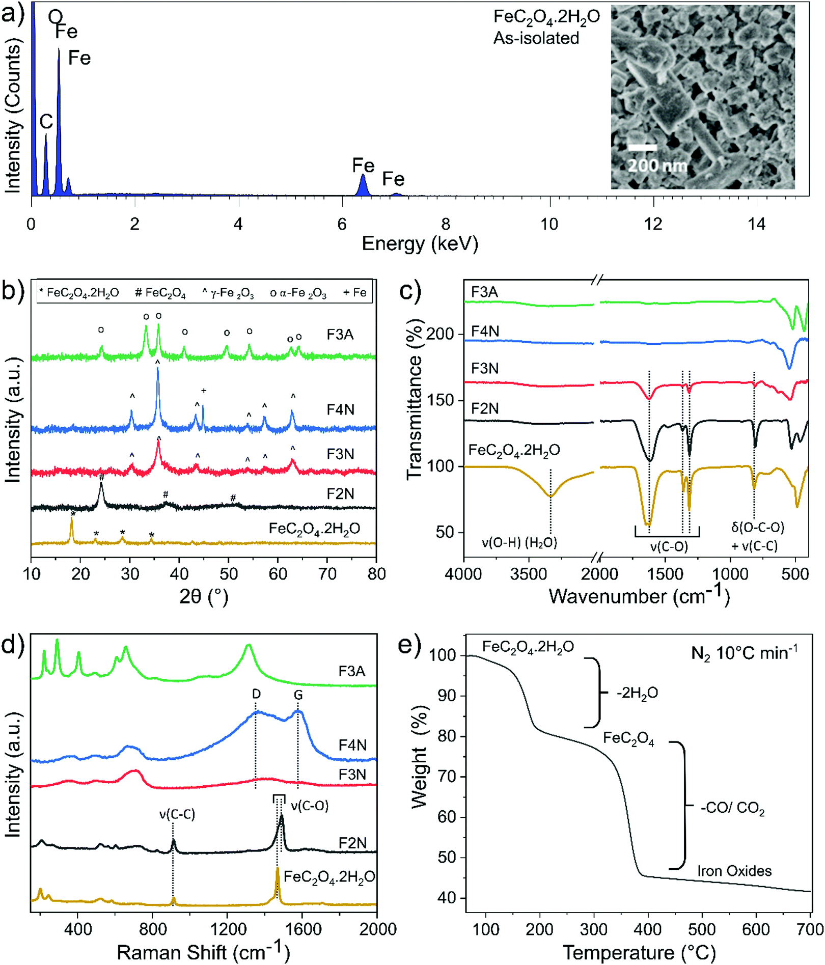 | ||
| Fig. 1 (a) SEM-EDX spectral data and (inset) SEM image of as-isolated material. (b) PXRD patterns (c) FTIR spectra, (d) Raman spectra of as-isolated and heat-treated FeC2O4·2H2O, revealing chemical and structural changes after heat treatment. (e) Weight loss profile of as-isolated FeC2O4·2H2O during thermal decomposition in N2 (10 °C min−1). | ||
 | ||
| Fig. 2 High-resolution (a) C1s and (b) O1s XPS spectra for FeC2O4·2H2O, F2N, F3N, F4N and F3A. Spectra are vertically offset for clarity, and the deconvoluted components corresponding to key chemical groups are indicated. The component S1 is assigned as a satellite structure,40 and components labelled T1 and T2 tentatively assigned to CO2 and bicarbonate species. | ||
FeC2O4·2H2O thermally decomposes (in N2) via two steps (Fig. 1e), the first at 150–200 °C (∼20% weight loss) corresponding with the loss of two H2O molecules, and the second from the decomposition of oxalate into gaseous species of CO and CO2.7,8 As the oxalate anion decomposes, the material oxidises to products predominantly composed of iron oxides, and a decrease in the sample's carbon content is expected.
Samples of anhydrous ferrous oxalate and iron oxides with different carbon contents were prepared via heat-treatment of the as-isolated material under different conditions. Heat treatment was performed at 200 °C, 300 °C and 400 °C in N2, and at 300 °C in air, and products are referred to as F2N, F3N, F4N and F3A, respectively. PXRD patterns matched the reference patterns for FeC2O4,7,12,13 γ-Fe2O3 (COD 9013529) and α-Fe2O3 (COD 1546383). Analysis of the PXRD patterns, FTIR and Raman spectra indicated that F2N, F3N, F4N and F3A were FeC2O4, γ-Fe2O3, γ-Fe2O3 with ca. 15% Fe, and α-Fe2O3, respectively (see ESI†). Carbon remained present in the samples under all heat treatment conditions, with a decrease in content when heat-treated in air and as temperature increased. The capability of the samples to retain carbon is supported by XPS and CHN elemental analysis. The C:Fe (atomic) ratio extracted from XPS survey spectra (reported in ESI,† Fig. S7) is approximately 2.7, 1.1, 0.9 and 0.7 for F2N, F3N, F4N and F3A respectively, indicating that the surface of F2N contains up to three times the amount of carbon compared to F4N. CHN analysis also showed that the bulk carbon content of F2N, F3N, F4N, and F3M is 12.2, 2.1, 0.9, and 0.5 wt% respectively.
While carbon in each sample was homogeneously distributed instead of being localised to specific grains (see Fig. 3 STEM-EDX), the chemical environment of carbon was different in each sample. Carbon present in F2N and F3N are associated with oxalate anions, and carbon in F4N and F3A attributed to carbonaceous residue from oxalate degradation. The presence of the FTIR peak at ca 1600 cm−1 observed for F3N indicates incomplete oxalate decomposition at 300 °C in N2, while the lower than theoretical carbon content for F2N (16.7 wt% for FeC2O4) suggests the possibility of some oxalate degradation. Destruction of oxalate carbonyl functional groups in F4N and F3A was indicated by the absence of the FTIR peak at 1600 cm−1. Meanwhile, the presence of carbonaceous residue in F3N and F4N was suggested by two Raman peaks (1670 and 1580 cm−1) occurring close to the expected Raman shifts for carbon D and G peaks. Although two broad bands in the similar region have been used as identification markers for γ-Fe2O3,42 other studies have attributed them to the possible presence of carbon resulting from burnt organic matter10,43,44 after finding that their appearance was independent of oxide type.43
 | ||
| Fig. 3 SEM and TEM images showing the morphology of heat-treated samples (F2N, F3N, F4N and F3A). STEM-EDX elemental maps of FeC2O4·2H2O after heat treatment showing the distribution of C, O and Fe. | ||
Differences in the chemical environment of carbon, and the degradation of oxalate anions on the surface of the material as heat-treatment temperature increased, were also supported by XPS results. For F2N, F3N, F4N and F3A, the C1s component (Fig. 2a) can be deconvolved with three synthetic peaks: the first component at 284.7 eV binding energy (BE) is attributed to C–C and C–H bonds; a second component at 286.4 eV can be ascribed to C–O bonds, while the highest BE component at 288.75 eV is attributed to O–C–O bonds.40 The relative intensity of the O–C–O to C–C peaks decreases as a function of the heat-treatment temperature, indicating that the samples treated at higher temperatures suffer a larger loss of O–C–O groups. The spectra of F4N and F3A, correspond to the C1s lineshape typical of physisorbed impurities on nominally carbon-free samples,45 indicating a complete loss of oxalate. These results are in line with Raman spectra, where the G and D peak (attributed to C–C bonds in the carbonaceous residue) can only be observed for F4N and, more faintly, in F3N. The O1s core levels (Fig. 2b) reflect the same scenario: a low binding energy component (530 eV) is detected for all samples and ascribed to the formation of Fe2O3 compound.46 A higher BE peak (532 eV), associated with O–C–O and C–O groups,40 is observed to decrease in intensity as a function of the annealing temperature of the sample. This component in F3A and F4N is attributed solely to the presence of impurities on the surface of the powders.
Morphologies of heat-treated samples are shown in Fig. 3. F2N had a porous structure similar to that published recently (see ESI,† Fig. S8),14 and a surface area of 89 m2 g−1. Oxide samples (F3N, F4N, F3A) consisted of plate-like particles, of which F4N had the largest particles (surface area of 42 m2 g−1). F3N and F3A consisted of smaller particles and had higher surface areas of 111 and 115 m2 g−1, respectively. The smaller specific surface area and sharper PXRD peaks observed for F4N, compared to F2N and F3N, suggest changes to the crystallinity of the products, with the formation of larger crystallite sizes at higher temperatures.
Electrochemical reactivity and cyclability
Galvanostatic cycling was performed at different current densities (50–400 mA g−1) to assess the cyclability of each material. Fig. 4a shows the specific discharge (lithiation) capacity with respect to cycle number. After 50 cycles at 100 mA g−1, F2N exhibited the highest capacity (767 mA h g−1 at 50th cycle). The capacity increased to 880 mA h g−1 when cycled at slower current densities (50 mA g−1 at cycle 55). Heat treatment under N2 at higher temperatures and in air, producing iron oxides, led to lower capacities; 370, 261, and 112 mA h g−1 were observed for F3A, F3N, and F4N respectively at the 50th cycle (100 mA g−1). The high capacity exhibited by F2N was retained after cycling at faster rates (200, 300, and 400 mA g−1), with a discharge capacity 810 mA h g−1 delivered at cycle 230 (100 mA g−1). Differences between the capacities of F2N and iron oxides (F3N, F4N, and F3A) may be attributed to differences in particle size, morphology and material composition; the latter potentially being the most significant.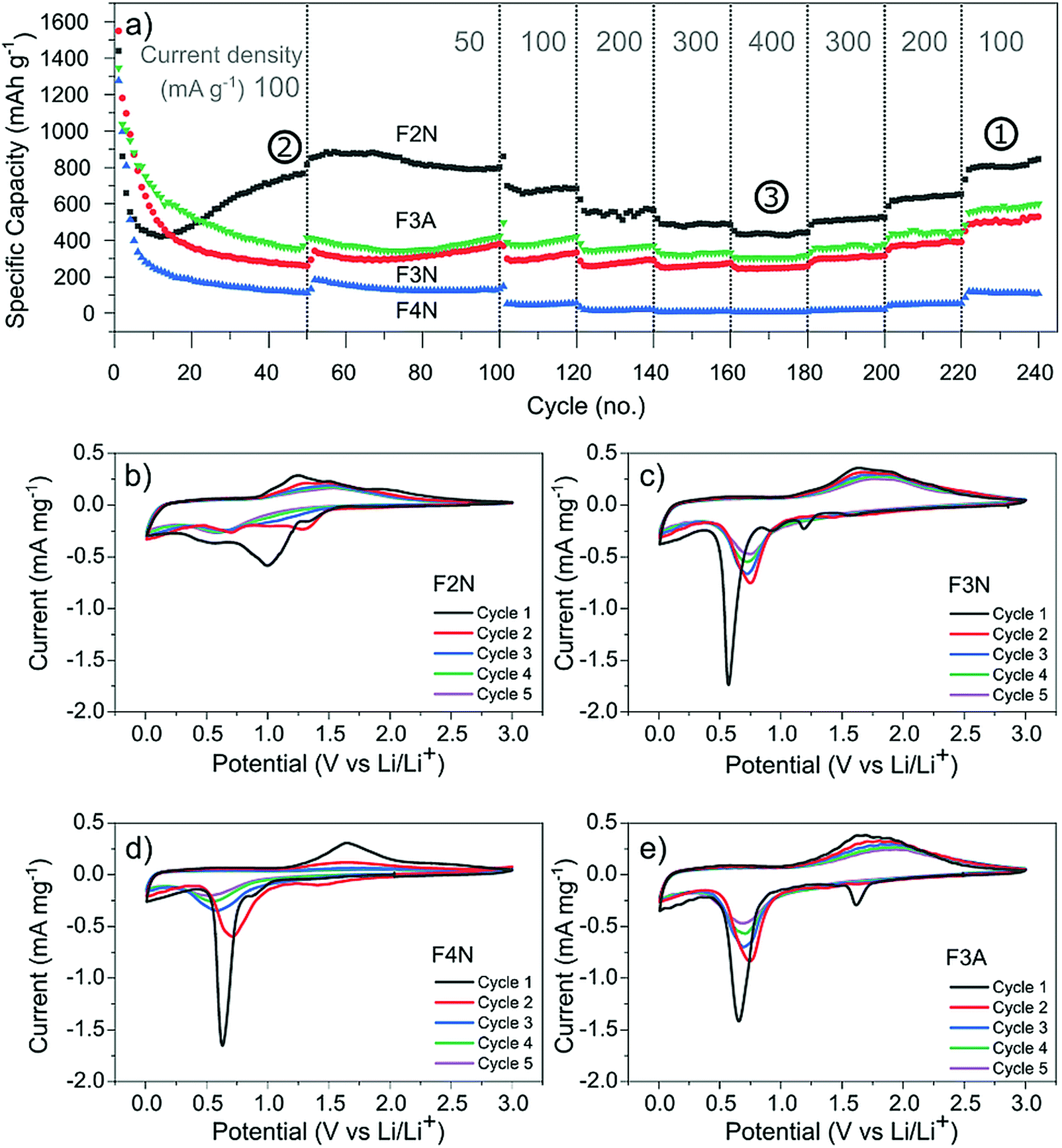 | ||
| Fig. 4 (a) Discharge capacity of heat-treated samples (F2N, F3N, F4N and F3A) during galvanostatic cycling at 50–400 mA g−1 (relative to the active material mass). Specific capacities used for determining carbon content per Ah (Fig. 7) are indicated by the numbers (1, 2, and 3). (b)–(e) Cyclic voltammograms of (b) F2N, (c) F3N, (d) F4N and (e) F3A between 3.0–0.0 V vs. Li/Li+ at a scan rate of 0.1 mV s−1. | ||
The electrochemical interactions of the active materials with Li were first investigated through cyclic voltammetry (CV) testing (Fig. 4b–e). In the first five CV cycles, F2N and iron oxide samples reflected the irreversible formation of an SEI layer, and the reversible conversion of Fe between the elemental and cationic oxidation state.
The CV curves for iron oxides (F3N, F4N and F3A), are relatively similar to each other, with the exceptions of reduction peaks observed during the first cathodic sweep, and the rate of current fade upon subsequent cycling. In the first cathodic sweep, four cathodic peaks were present for F3N (1.55, 1.19, 0.92, 0.57 V), while three peaks were seen for F4N (1.5, 0.86, 0.63 V) and two for F3A (1.6, 0.65 V). The strongest cathodic peak in F3N, F4N, F3A (0.57, 0.63, 0.65 V respectively) can be associated with the reduction of Fe cations to Fe0 and irreversible reactions associated with electrolyte decomposition.47 The remaining cathodic peaks in the first cycle may be ascribed to the insertion of Li+ into Fe2O3 and irreversible formation of the rock-salt lithiated iron oxides phases.48–50 The broad anodic peak arises from the oxidation of Fe0 to Fe3+. This oxidation process occurs in multiple steps, Fe0 to Fe2+ and Fe2+ to Fe3+, with two overlapping peaks visible in the initial cycles.51,52 Subsequent cycling resulted in a single redox peak pair attributed to the shuffling of Fe species between the rock salt phase and a composite containing Fe0 and Li2O.
The first cathodic scan for F2N consisted of three reduction peaks (1.32, 0.99, 0.54 V), two of which (0.99, 1.32 V) eventually became absent in subsequent cycles. The third peak, at 0.54 V, shifted to 0.67 V in the second cycle before shifting back and settling at 0.57 V in subsequent cycles. Since Fe0 forms when FeC2O4 reacts with Li+ during discharge,12 it is likely that the processes occurring during the initial lithiation of iron oxides also occur for FeC2O4. Hence the cathodic peaks observed may be associated with the insertion of Li+ into FeC2O4 followed by the formation of Fe0 in a matrix of Li2C2O4,12 and the development of an SEI.13,50,53,54 The number of distinct anodic peaks decreased as cycling progressed. Several overlapping peaks appeared in the first cycle, the most prominent ones observed at 1.2, 1.5, 1.9 V (broad) and at 1.0 V (shoulder), while two broad peaks were seen in cycle two (1.3, 1.5 V), and one very broad peak at 1.5 V in subsequent cycles. Anodic peaks arise due to the oxidation of Fe0 particles to oxidation states close to Fe3+.12 The presence of multiple anodic peaks suggests the occurrence of several possible processes including multi-step oxidation, Fe0 to Fe3+via Fe2+,51,52 possible redox reactions involving the oxalate ion,15 and irreversible electrolyte reactions.
Amongst the four materials tested, F4N exhibited the greatest decrease in anodic and cathodic peak currents, along with the largest potential difference between cathodic and anodic peaks. These observations indicate high polarisation effects and irreversibility in the redox reactions, attributed to the large particle size and electrochemical pulverisation.55 Both attributions are detrimental to electrode kinetics due to the lower contact area between active materials and electrolyte, and longer Li+ diffusion distances. F3N and F3A both showed signs of irreversibility in the form of decreasing cathodic and anodic peak currents, albeit to a lesser extent than F4N. The cathodic peaks for F3N, F4N and F3A shift to a more positive potential in cycle two. This is associated with a reduction in polarisation resistance, most likely due to Li+ diffusion being easier after the establishment of diffusion pathways during the first cycle. While the cathodic peak for F3N and F3A observed in cycles 3 to 5 remained at higher potentials than that of cycle 1, the cathodic peak potential for F4N shifts to a more negative value after cycle two, suggesting that subsequent degradation of F4N occurred and led to poorer Li+ diffusion kinetics in cycles three to five.
In contrast, cathodic and anodic peak currents for F2N were more consistent after cycle one, indicating greater reversibility. Smaller specific peak currents for F2N compared to iron oxides suggest lower electrochemical activity of FeC2O4, possibly due to the higher molecular weight (per mole of Fe) of FeC2O4. Differences in molecular structures may also explain the lower oxidation potential observed for F2N since the presence of ligands can influence redox potentials of metal cations.56
Capacity contributions and trends
The total capacity observed can be broadly categorised into contributions from processes that are diffusion-controlled and those that occur at or near the surface of the particles, with the latter referred to as capacitive contributions. Processes that are diffusion-controlled include bulk faradaic reactions. Fig. 5 summarises the approximate proportion of total capacity contributed to by capacitive processes for each material. The values were estimated via a method reported elsewhere.57,58 This method includes performing cyclic voltammetry at different voltage sweep rates (ν) and is based on the assumption that the total current response at each potential (i) can be described viaeqn (3); kcν and kdν1/2 correspond to current contributions from capacitive and diffusion-controlled processes, respectively.| i(V) = kcν + kdν1/2 | (3) |
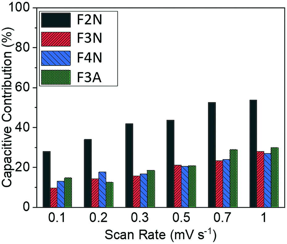 | ||
| Fig. 5 Capacitive contributions for heat-treated materials at scan rates of 0.1–1 mV s−1 for F2N, F3N, F4N and F3A. | ||
Results summarised in Fig. 5 suggest that the proportion of capacity contributed to by capacitive processes was the highest for F2N, despite F2N not having the highest BET surface area. This observation may be attributed to the reversible formation of a polymeric gel film which has a possible pseudocapacitive effect.17,18 It is possible that the oxalate anions in F2N facilitate the reversible formation of the gel film to a greater extent than the oxide samples, since the oxalate anion contains carboxylate functional groups, which are not too dissimilar from the carbonates present in the electrolyte that react to form the polymeric gel layer,17
Discharge capacities of each material varied as cycle number increased, during galvanostatic cycling (Fig. 4). During the initial cycles, capacity fade was observed for all four materials. This decrease has been widely attributed to the formation of an unstable SEI layer and electrochemical pulverisation.59 The latter relates to the cracking and crumbling of the active material as a result of structural reorganisation to form separate phases (Li2O/Li2C2O4 and Fe0), and the repeated volumetric expansion and contraction from charging and discharging, leading to particles that are isolated from lithium processes.
After the initial capacity decrease, a prominent increase in capacity was observed for F2N (at ca. cycle 10). Capacity increase was also observed for F3N and F3A at around cycle 70, although this was significantly smaller than F2N. Increasing capacity after the initial decrease has been reported for conversion-type electrodes, and has been attributed to different processes and reactions.17,19,60,61 One explanation involves the reversible formation of the polymeric gel film previously mentioned.17 The increase in capacity arises from charge transfer processes involved in the reversible formation the polymeric gel layer, and the reactivation of active material in the presence of the polymeric gel layer.17,18,21
The larger increase in capacity observed for F2N, compared to iron oxides, may be attributed to a greater extent of polymeric gel layer formation, which potentially stems from the presence of oxalate anions in F2N. The greater extent of polymeric gel layer formation in F2N is, as previously mentioned, suggested by F2N having the highest capacitive contribution (Fig. 5).
To further investigate capacity trends and contributions, the potential profiles and differential capacity (dQ/dE) of each material as cycle number increased were analysed (Fig. 6). Aside from the specific discharge capacity, potential profiles for the oxide samples (F3N, F4N and F3A) were relatively similar. The potential profile for the first two discharges (cycle 0 and 1) consisted of a distinct voltage plateau, which can be attributed to the reduction of iron oxide to Fe0 and Li2O. As the oxide materials were cycled, the voltage plateau during discharge shortened, reflecting a decline in the number of electrons required to reduce iron oxide to Fe0.62 This was also reflected in the decrease in differential capacity at all potentials (0–3 V), particularly at the reduction and oxidation potentials for iron, during charging and discharging. The decline in the quantity of active material undergoing conversion reaction may be partially attributed to the isolation of active material from electrochemical reactions, resulting from particle pulverisation. Another reason includes the inability to fully reverse the conversion reaction due to increased kinetic resistance for Li+ migration, resulting from the presence of Li2O and an increase in SEI layer thickness, leading to a build-up of Fe0.50
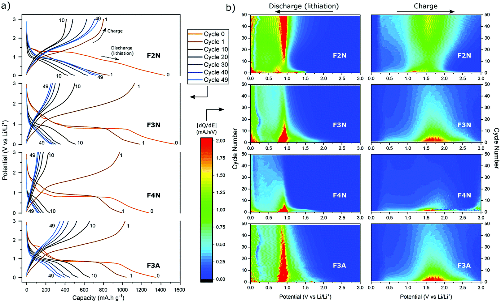 | ||
| Fig. 6 (a) Potential profiles and (b) differential capacity maps of F2N, F3N, F4N and F3A galvanostatically cycled 50 times at 100 mA g−1. Differential capacity maps during discharge and charging show the changes to the charge and discharge capacity delivered at each potential as cycling progressed. | ||
The charging and discharging potential profiles for F2N have a more sloping characteristic, and a less prominent voltage plateau from the start, compared to the oxide samples. The potential profile for the first discharge consists of multiple short plateaus; with their presence reflected as regions of high differential capacity (near cycle 0 in Fig. 6b). This matches the multiple cathodic peaks observed during cyclic voltammetry testing. Their presence indicates the occurrence of more electrochemical processes during the first cycle, compared to the oxide samples. As cycling progresses, the discharge potential profile becomes similar to those of the oxide samples, consisting of one short voltage plateau at ca. 0.9 V (see cycle 10). In contrast to the oxide samples, the voltage plateau at 0.9 V becomes more prominent upon further cycling. These changes are more clearly seen as the increases in the differential capacity at potentials associated with the redox reaction of Fe cations (ca. 0.9 V during discharge and 1.5 V during charging, in Fig. 6b). These suggest that, as cycling progresses, the possibility of a gradual activation of Fe species increases and hence an increase in the number of electrons involved in the conversion reaction.
While electrochemical pulverisation leads to electrical isolation of the active material, resulting in a decrease in capacity, reversible formation of the polymeric gel film may play a role in the recovery and increase in capacity. Further to the additional capacity contributions, the reversible formation of a polymeric gel film has been found to provide mechanical cohesion between the nano-granular conversion reaction products, helping electroactive species to stay within electrical contact,17 and impede the agglomeration of particles.18 It is therefore possible that, as cycling progresses, the growth or swelling of the polymer gel film links up previously electronically isolated pieces, leading to the gradual reactivation of the active material. Such a proposal would be similar to that reported for metal oxides.21
Despite the improved performance of ferrous oxalate compared to oxides derived from oxalates, challenges commonly seen in conversion-type materials are still present. In particular, the sloping voltage profile, especially after substantial cycling, makes it less ideal than a material with a well-defined voltage plateau, as a sloping voltage profile translates to variations in the cell voltage during operation. Further understanding of the high capacities and increases in capacity is also required to determine the long-term impact and stability of the underlying processes.
Carbon and energy storage evaluation
One intention of the synthesis method reported here was to determine if CO2 can be converted into energy storage materials. The utilisation of CO2 as a means of reducing CO2 emissions may be more effective if the carbon is retained or ‘stored’ in the product. In this context, a material synthesised from CO2 that has a higher carbon content is therefore more desirable. Meanwhile, a material that has a higher specific capacity is favoured more when considering electrochemical performance. Consequently, both the capacities and carbon content of each material (F2N, F3N, F4N and F3A) were considered when evaluating which material is preferred. For the purpose of this study, only carbon content in the synthesised materials, and carbon released from the materials during heat treatment are considered. All calculations are detailed in the ESI.†F2N showed better prospects as an energy storage material synthesised from CO2, compared to the oxide samples. This arises from the combination of three factors; (1) production of F2N resulted in the least amount of carbon released back into the atmosphere, (2) F2N has the highest carbon content per gram of active material, and (3) F2N exhibiting the largest specific capacity.
The first two points arose from minimal oxalate decomposition achieved at 200 °C in N2, which also led to less as-isolated FeC2O4·2H2O required to obtain a given mass of heat-treated material. 1.3, 2, 1, and 1 g of as-isolated FeC2O4·2H2O was required to obtain 1 g of F2N, F3N, F4N and F3A respectively. Considering the amount of carbon in the required quantity of as-isolated FeC2O4·2H2O, heat treatment to obtain F2N, F3N, F4N and F3A resulted in 18, 91, 96 and 98% loss of the ‘stored’ carbon, respectively (see Fig. 7a).
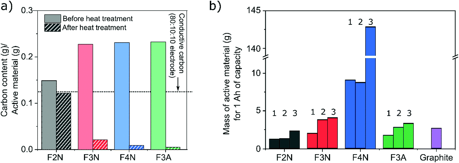 | ||
| Fig. 7 Carbon content of heat-treated samples. (a) Amount of carbon per gram of heat-treated material before and after heat treatment. (b) Mass of heat-treated material required to store 1 A h of capacity at three scenarios; (1) cycle 220–240, 100 mA g−1, (2) 50th cycle, 100 mA g−1, (3) average at 400 mA g−1. The value for graphite is provided as a reference, and is based on its theoretical capacity. | ||
The second and third points translate to a lower mass of active material required for, and more carbon present in, 1 A h worth of F2N, compared to the oxide samples (see Fig. 7b and Table 1). Due to the changes in the discharged capacities observed, calculations were based on three discharge capacities (identified in Fig. 4) for each material; (1) the lowest observed capacity in the last 20 cycles at 100 mA g−1 was taken as the reversible capacity at 100 mA g−1; (2) capacity recorded at the 50th cycle at 100 mA g−1 to negate possible influences of cycling at higher current densities, and; (3) average capacity observed while cycling at 400 mA g−1. The amount of active material and carbon content were both considered in this discussion since large quantities of carbon present per ampere-hour of material can also be achieved in materials with low specific discharge capacities, since more active material is required (see F4N).
| Material | Mass of carbon (g) in 1 A h of active material | ||
|---|---|---|---|
| Scenario 1 | Scenario 2 | Scenario 3 | |
| F2N | 0.15 | 0.16 | 0.28 |
| F3N | 0.04 | 0.08 | 0.09 |
| F4N | 0.08 | 0.08 | 1.29 |
| F3A | 0.01 | 0.01 | 0.02 |
| Graphite | 2.69 | ||
The presence of conductive carbon additives in the working electrode was also considered. The quantity of carbon per gram of F2N is comparable to the amount of conductive carbon present in the working electrode, with 0.125 g conductive carbon per gram of F2N (0.12 g carbon, Fig. 7a) based on the electrode composition used (80 wt% active material 10 wt% conductive carbon and 10 wt% polymer binder). While increasing the proportion of conductive carbon decreases the significance of carbon present in the active material, increases to the total amount of carbon per unit mass of working electrode and enhancements in the electrochemical performance of the active material can be expected. However, the mass of conductive carbon must also be accounted for in these future studies, to ensure that the specific capacity of the entire working electrode is not compromised.
While iron oxalate electrodes contain less carbon than graphite-based material, they display capacities larger than the theoretical capacity of graphite. This, coupled with their synthesis from waste scrap steel, demonstrates that oxalates are worthy of further study as sustainable battery materials.
Conclusion
In the present study, a method to synthesise energy storage materials from carbon dioxide and scrap mild steel was demonstrated. Nanostructured anhydrous FeC2O4 and iron oxides were produced as negative electrode materials in lithium-ion batteries, via an electrochemical process and subsequent heat treatment. Higher heat treatment temperatures resulted in a greater extent of oxalate decomposition into oxides and a lower residual carbon.Compared to iron oxides prepared at 300 °C and 400 °C, FeC2O4 was produced at a lower temperature of 200 °C, leading to greater retention of carbon from the original material. FeC2O4 also exhibited higher specific capacities, with the enhanced electrochemical performance potentially due to the presence of oxalate anions which facilitates the formation of a reversible polymeric gel layer. Consequently, FeC2O4 showed more promise as an energy storage material synthesised from CO2, compared to the oxides prepared from oxalates.
While further life cycle analysis of the process and materials would provide a clearer idea of the feasibility of utilising CO2 to produce energy storage materials, the results presented indicate that oxalates may provide a better opportunity as sustainable battery materials than oxides derived from oxalates.
Conflicts of interest
There are no conflicts to declare.Acknowledgements
The authors thank Associate Prof. Yuerui Lu for the use of the tube furnace (SKGL-1200), and Kun Liang and Jian Zhang for their assistance with its operation. The authors also thank Prof. David Nisbet for the use of the Bruker Alpha Platinum-ATR unit, and Stephen Boyer at London Metropolitan University for carrying out CHN elemental analysis. The authors acknowledge the facilities and the scientific and technical assistance of Microscopy Australia at the Advanced Imaging Precinct, Australian National University, a facility that is funded by the University, State and Federal Governments. The authors acknowledge use of facilities within the Monash X-ray Platform. I. D. B. supported by the FLEET Centre of Excellence, ARC Grant No. CE170100039.References
- D. Larcher and J. M. Tarascon, Nat. Chem., 2015, 7, 19–29 CrossRef CAS.
- J. M. Tarascon and M. Armand, Nature, 2001, 414, 359–367 CrossRef CAS.
- M. V. Reddy, G. V. Subba Rao and B. V. R. Chowdari, Chem. Rev., 2013, 113, 5364–5457 CrossRef CAS.
- S. Guo, G. Lu, S. Qiu, J. Liu, X. Wang, C. He, H. Wei, X. Yan and Z. Guo, Nano Energy, 2014, 9, 41–49 CrossRef CAS.
- L. Guo, H. Arafune and N. Teramae, Langmuir, 2013, 29, 4404–4412 CrossRef CAS.
- D. Dollimore, Thermochim. Acta, 1987, 117, 331–363 CrossRef CAS.
- R. A. Brown and S. C. Bevan, J. Inorg. Nucl. Chem., 1966, 28, 387–391 CrossRef CAS.
- K. S. Rane, A. K. Nikumbh and A. J. Mukhedkar, J. Mater. Sci., 1981, 16, 2387–2397 CrossRef CAS.
- P. Niu, T. Wu, L. Wen, J. Tan, Y. Yang, S. Zheng, Y. Liang, F. Li, J. T. S. Irvine, G. Liu, X. Ma and H.-M. Cheng, Adv. Mater., 2018, 30, 1705999 CrossRef.
- M. Li, W. Wang, M. Yang, F. Lv, L. Cao, Y. Tang, R. Sun and Z. Lu, RSC Adv., 2015, 5, 7356–7362 RSC.
- J. S. Yeoh, C. F. Armer and A. Lowe, Mater. Today Energy, 2018, 9, 198–222 CrossRef.
- M. J. Aragón, B. León, C. Pérez Vicente and J. L. Tirado, Inorg. Chem., 2008, 47, 10366–10371 CrossRef.
- W. A. Ang, N. Gupta, R. Prasanth and S. Madhavi, ACS Appl. Mater. Interfaces, 2012, 4, 7011–7019 CrossRef CAS.
- K. Zhang, Y. Li, Y. Wang, J. Zhao, X. Chen, Y. Dai and Y. Yao, Chem. Eng. J., 2020, 384, 123281 CrossRef CAS.
- W. Yao, A. R. Armstrong, X. Zhou, M.-T. Sougrati, P. Kidkhunthod, S. Tunmee, C. Sun, S. Sattayaporn, P. Lightfoot, B. Ji, C. Jiang, N. Wu, Y. Tang and H.-M. Cheng, Nat. Commun., 2019, 10, 3483 CrossRef.
- S. Solchenbach, M. Wetjen, D. Pritzl, K. U. Schwenke and H. A. Gasteiger, J. Electrochem. Soc., 2018, 165, A512–A524 CrossRef CAS.
- S. Laruelle, S. Grugeon, P. Poizot, M. Dollé, L. Dupont and J.-M. Tarascon, J. Electrochem. Soc., 2002, 149, A627–A634 CrossRef CAS.
- S. Grugeon, S. Laruelle, L. Dupont and J. M. Tarascon, Solid State Sci., 2003, 5, 895–904 CrossRef CAS.
- K. M. Shaju, F. Jiao, A. Débart and P. G. Bruce, Phys. Chem. Chem. Phys., 2007, 9, 1837–1842 RSC.
- X. Wu, J. Guo, M. J. McDonald, S. Li, B. Xu and Y. Yang, Electrochim. Acta, 2015, 163, 93–101 CrossRef CAS.
- B. Long, L. Luo, J. Zhang, M.-S. Balogun, S. Song and Y. Tong, Mater. Today Energy, 2018, 9, 311–318 CrossRef.
- M. C. Rowley, H. Estrada-Medina, M. Tzec-Gamboa, A. Rozin, G. Cailleau, E. P. Verrecchia and I. Green, Plant Soil, 2017, 412, 465–479 CrossRef CAS.
- G. M. Gadd, J. Bahri-Esfahani, Q. Li, Y. J. Rhee, Z. Wei, M. Fomina and X. Liang, Fungal Biol. Rev., 2014, 28, 36–55 CrossRef.
- J. Qiao, Y. Liu and J. Zhang, Electrochemical Reduction of Carbon Dioxide: Fundamentals and Technologies, CRC Press, 2016 Search PubMed.
- I. Kaname, I. Shoichiro, Y. Nobuhiro, I. Takaya and T. Takehiko, Bull. Chem. Soc. Jpn., 1985, 58, 3027–3028 CrossRef.
- I. Shoichiro, T. Takehiko and I. Kaname, Bull. Chem. Soc. Jpn., 1987, 60, 2517–2522 CrossRef.
- M. König, J. Vaes, E. Klemm and D. Pant, iScience, 2019, 19, 135–160 CrossRef.
- D. Prat, A. Wells, J. Hayler, H. Sneddon, C. R. McElroy, S. Abou-Shehada and P. J. Dunn, Green Chem., 2016, 18, 288–296 RSC.
- A. R. Paris and A. B. Bocarsly, ACS Catal., 2019, 9, 2324–2333 CrossRef CAS.
- A. Gennaro, A. A. Isse and E. Vianello, J. Electroanal. Chem. Interfacial Electrochem., 1990, 289, 203–215 CrossRef CAS.
- W. Lv, R. Zhang, P. Gao, C. Gong and L. Lei, J. Solid State Electrochem., 2013, 17, 2789–2794 CrossRef CAS.
- M. Jitaru, D. A. Lowy, M. Toma, B. C. Toma and L. Oniciu, J. Appl. Electrochem., 1997, 27, 875–889 CrossRef CAS.
- R. J. Lim, M. Xie, M. A. Sk, J.-M. Lee, A. Fisher, X. Wang and K. H. Lim, Catal. Today, 2014, 233, 169–180 CrossRef CAS.
- P. A. Christensen and S. J. Higgins, J. Electroanal. Chem., 1995, 387, 127–132 CrossRef.
- U. R. Pokharel, F. R. Fronczek and A. W. Maverick, Nat. Commun., 2014, 5, 5883 CrossRef CAS.
- R. Angamuthu, P. Byers, M. Lutz, A. L. Spek and E. Bouwman, Science, 2010, 327, 313–315 CrossRef CAS.
- G.-R. Li, H. Xu, X.-F. Lu, J.-X. Feng, Y.-X. Tong and C.-Y. Su, Nanoscale, 2013, 5, 4056–4069 RSC.
- Y. Yuan and A. Lei, Nat. Commun., 2020, 11, 802 CrossRef CAS.
- I. Jung, J. Choi and Y. Tak, J. Mater. Chem., 2010, 20, 6164–6169 RSC.
- S. Chenakin and N. Kruse, Appl. Surf. Sci., 2020, 515, 146041 CrossRef CAS.
- C. Yang, F. Bebensee, J. Chen, X. Yu, A. Nefedov and C. Wöll, ChemPhysChem, 2017, 18, 1874–1880 CrossRef CAS.
- L. Mazzetti and P. J. Thistlethwaite, J. Raman Spectrosc., 2002, 33, 104–111 CrossRef CAS.
- M. Hanesch, Geophys. J. Int., 2009, 177, 941–948 CrossRef CAS.
- A. S. Rajan, S. Sampath and A. K. Shukla, Energy Environ. Sci., 2014, 7, 1110–1116 RSC.
- X. Gao, I. Di Bernardo, P. Kreider, T. Tran-Phu, X. Cai, N. Wang, Y. Zhu, M. B. Venkataraman, J. Lipton-Duffin, A. Bayon, W. Lipiński and A. Tricoli, ACS, Catalysis, 2019, 9, 9880–9890 CAS.
- S.-S. Li, W.-J. Li, T.-J. Jiang, Z.-G. Liu, X. Chen, H.-P. Cong, J.-H. Liu, Y.-Y. Huang, L.-N. Li and X.-J. Huang, Anal. Chem., 2016, 88, 906–914 CrossRef CAS.
- S. Jin, H. Deng, D. Long, X. Liu, L. Zhan, X. Liang, W. Qiao and L. Ling, J. Power Sources, 2011, 196, 3887–3893 CrossRef CAS.
- D. Larcher, C. Masquelier, D. Bonnin, Y. Chabre, V. Masson, J.-B. Leriche and J.-M. Tarascon, J. Electrochem. Soc., 2003, 150, A133–A139 CrossRef CAS.
- L. Wang, Y. Yu, P. C. Chen, D. W. Zhang and C. H. Chen, J. Power Sources, 2008, 183, 717–723 CrossRef CAS.
- J. Li, S. Hwang, F. Guo, S. Li, Z. Chen, R. Kou, K. Sun, C.-J. Sun, H. Gan, A. Yu, E. A. Stach, H. Zhou and D. Su, Nat. Commun., 2019, 10, 2224 CrossRef.
- J. Morales, L. Sánchez, F. Martín, F. Berry and X. Ren, J. Electrochem. Soc., 2005, 152, A1748–A1754 CrossRef CAS.
- M. V. Reddy, T. Yu, C. H. Sow, Z. X. Shen, C. T. Lim, G. V. SubbaRao and B. V. R. Chowdari, Adv. Funct. Mater., 2007, 17, 2792–2799 CrossRef CAS.
- J. Chen, L. Xu, W. Li and X. Gou, Adv. Mater., 2005, 17, 582–586 CrossRef CAS.
- D. Larcher, D. Bonnin, R. Cortes, I. Rivals, L. Personnaz and J.-M. Tarascon, J. Electrochem. Soc., 2003, 150, A1643–A1650 CrossRef CAS.
- D. McNulty, H. Geaney, E. Carroll, S. Garvey, A. Lonergan and C. O’Dwyer, Mater. Res. Express, 2017, 4, 025011 CrossRef.
- H. Gomathi, Bull. Electrochem., 2000, 16, 10 Search PubMed.
- J. Wang, J. Polleux, T. Brezesinski, S. Tolbert and B. Dunn, ECS Trans., 2008, 11, 101–111 CrossRef CAS.
- V. Augustyn, P. Simon and B. Dunn, Energy Environ. Sci., 2014, 7, 1597–1614 RSC.
- C. He, S. Wu, N. Zhao, C. Shi, E. Liu and J. Li, ACS Nano, 2013, 7, 4459–4469 CrossRef CAS.
- Y.-Y. Hu, Z. Liu, K.-W. Nam, O. J. Borkiewicz, J. Cheng, X. Hua, M. T. Dunstan, X. Yu, K. M. Wiaderek, L.-S. Du, K. W. Chapman, P. J. Chupas, X.-Q. Yang and C. P. Grey, Nat. Mater., 2013, 12, 1130 CrossRef CAS.
- Y. Chai, X. Wang, Y. Yu, X. Shi, Q. Zhang and N. Wang, Int. J. Energy Res., 2019, 43, 6045–6055 CrossRef CAS.
- D. Puthusseri, M. Wahid and S. Ogale, ACS Omega, 2018, 3, 4591–4601 CrossRef CAS.
Footnote |
| † Electronic supplementary information (ESI) available. See DOI: 10.1039/d0ma00588f |
| This journal is © The Royal Society of Chemistry 2021 |