
 Open Access Article
 This Open Access Article is licensed under a Creative Commons Attribution-Non Commercial 3.0 Unported Licence
Bridging the academic–industrial gap: application of an oxygen and pH sensor-integrated lab-on-a-chip in nanotoxicology†
Helene
Zirath‡
 *ab,
Sarah
Spitz‡
ab,
Doris
Roth
ab,
Tobias
Schellhorn
a,
Mario
Rothbauer
bc,
Bernhard
Müller
d,
Manuel
Walch
e,
Jatinder
Kaur
e,
Alexander
Wörle
e,
Yvonne
Kohl
f,
Torsten
Mayr
d and
Peter
Ertl
*ab
*ab,
Sarah
Spitz‡
ab,
Doris
Roth
ab,
Tobias
Schellhorn
a,
Mario
Rothbauer
bc,
Bernhard
Müller
d,
Manuel
Walch
e,
Jatinder
Kaur
e,
Alexander
Wörle
e,
Yvonne
Kohl
f,
Torsten
Mayr
d and
Peter
Ertl
*ab
aInstitute of Applied Synthetic Chemistry and Institute of Chemical Technologies and Analytics, Faculty of Technical Chemistry, Vienna University of Technology, Getreidemarkt 9/163-164, 1060 Vienna, Austria. E-mail: helene.zirath@tuwien.ac.at; peter.ertl@tuwien.ac.at
bAustrian Cluster for Tissue Regeneration, Vienna, Austria
cKarl Chiari Lab for Orthopaedic Biology, Department of Orthopedics and Trauma Surgery, Medical University of Vienna, Währinger Gürtel 18-20, 1090 Vienna, Austria
dInstitute of Analytical Chemistry and Food Chemistry, Graz University of Technology, Stremayrgasse 9, 8010 Graz, Austria
ekdg opticomp GmbH, Am kdg Campus, Dorf 91, 6652 Elbigenalp, Austria
fFraunhofer Institute for Biomedical Engineering IBMT, 66280 Sulzbach, Germany
First published on 21st September 2021
Abstract
Translation of advanced cell-based assays exhibiting a higher degree of automation, miniaturization, and integration of complementary sensing functions is mainly limited by the development of industrial-relevant prototypes that can be readily produced in larger volumes. Despite the increasing number of academic publications in recent years, the manufacturability of these microfluidic cell cultures systems is largely ignored, thus severely restricting their implementation in routine toxicological applications. We have developed a dual-sensor integrated microfluidic cell analysis platform using industrial specifications, materials, and fabrication methods to conduct risk assessment studies of engineered nanoparticles to overcome this academic–industrial gap. Non-invasive and time-resolved monitoring of cellular oxygen uptake and metabolic activity (pH) in the absence and presence of nanoparticle exposure is accomplished by integrating optical sensor spots into a cyclic olefin copolymer (COC)-based microfluidic platform. Results of our nanotoxicological study, including two physiological cell barriers that are essential in the protection from exogenous factors, the intestine (Caco-2) and the vasculature (HUVECs) showed that the assessment of the cells' total energy metabolism is ideally suited to rapidly detect cytotoxicities. Additional viability assay verification using state-of-the-art dye exclusion assays for nanotoxicology demonstrated the similarity and comparability of our results, thus highlighting the benefits of employing a compact and cost-efficient microfluidic dual-sensor platform as a pre-screening tool in nanomaterial risk assessment and as a rapid quality control measure in medium to high-throughput settings.
Introduction
Nanoparticles present a growing field within the industrial and medicinal sectors because of their wide spectra of advantageous properties. Due to their small nanometer dimensions, nanomaterials display a high surface-to-volume ratio, causing the properties of the surface layer to dominate over those of the bulk material, altering the material's intrinsic properties.1 The resulting unique mechanical, magnetic, and electric properties, as well as the strong surface reactivity, make nanomaterials highly valuable in various fields, including electronics, cosmetics, diagnostics, drug delivery, and the food industry.2–5 Unfortunately, the often-unknown effects of nanoparticles on human health are still restricting their broader application, especially within the food industry and cosmetics, where their usage is still highly debated.5 One of the main problems is that collateral toxic health effects associated with nanoparticle exposure are impossible to predict based on their physicochemical properties alone. Consequently, toxicological testing has therefore been highly recommended for all nanomaterials6–8 to better understand the interrelationship between nanoparticle exposure and human health.9 Conventional methods for testing the safety of nanomaterials include in vivo animal models, which, apart from pressing ethical concerns, present a labor-, time-, and cost-intensive endeavor. Additionally, pre-existing genotypic and phenotypic differences between humans and animals, e.g., rodents, decrease the tests' validity and translatability.10 Alternatively, in vitro, cell-based assays, e.g., MTT, calcein-AM/PI, or WST-1 assays, are performed to assess the impact of nanoparticle exposure on cell viability, which in addition can be supported by morphological analysis.11 Since standard in vitro cell-based assays are performed in microtiter plates, they are limited to static cultivation conditions and time-consuming (45 min–4 h), invasive endpoint analysis. The absence of fluid flow, moreover, can result in the gravitational settling of nanoparticles, ultimately favoring nanoparticle aggregation, which has been linked to the creation of physiochemical stress as well as cell death.12,13 In other words, reported cytotoxicities using static cell culture conditions may not represent the actual toxicity levels of the investigated nanomaterials. This methodological limitation impacts the predictability of nanotoxicological evaluations, as uptake, accumulation, and biopersistence of nanoparticles in vivo are primarily governed by dynamic microenvironments.We have recently demonstrated that nanoparticle uptake and thus toxicity is strongly modulated by fluid flow, resulting in a strong increase in endocytosis mediated nanoparticle uptake with increasing flow rates up to a critical maximum flow rate above which nanoparticle uptake is severely restricted.14
Its inherent ability to provide precise spatial and temporal control over fluid dynamics, coupled with low sample volumes and a high degree of flexibility, has rendered microfluidics a promising tool in nanotoxicology, as it allows for the recapitulation of physiological scenarios such as the dynamic nanoparticle exposure of cells within the human body in custom-made platforms.12,15 In addition, the option to integrate electrical or optical sensors further equips microfluidics with the ability to non-invasively monitor various critical parameters such as cell-to-cell, cell-to-substrate interactions as well as metabolic activity.16–18 Herein, the combinatorial monitoring of oxygen consumption rates (OCR) and acidification rates (ECAR) has proven to be a powerful strategy as it enables the assessment of metabolic shifts or, more specifically, of cytotoxicological effects exerted upon the cell by the uptake of nanoparticles.
While several commercial and academic platforms (see ESI† Table S1) that allow for the assessment of the two physiological parameters OCR and ECAR have been developed, including the Agilent's MitoXpress assay, the Agilent's Seahorse XF analyzer platform, the O2k-FluoRespirometer (Orobos), the SC 1000 Metabolic Chip (Bionas), and the Biochip D (Cellasys), these platforms often fail to account for essential aspects such as dynamic microenvironments, low-production costs, high throughput as well as manufacturing scalability. Among these commercially available platforms, only one technology allows for the integration of the biophysical stimuli fluid flow. Unfortunately, the broad applicability of this system is hampered by the use of an electrochemical sensing approach, low throughput (n = 6) coupled with a comparatively large footprint. The use of an electrochemically based read-out also constitutes one of the most significant disadvantages of current academic strategies,40–44 as these approaches have been associated with complex integration procedures, the dependency on reference electrodes as well as potential interferences through the consumption of the analyte of interest.
Optical sensing strategies, on the other hand, provide a great alternative as they combine easy miniaturization, integration, and external read-out with low manufacturing costs. Furthermore, optical sensor spots have already shown great promise in determining several essential cell functions, including cell cycle stage, viability, apoptosis, and necrosis, by detecting pericellular concentrations of dissolved oxygen.19 In addition to cellular respiration, the metabolic activity of cells defined by the accumulation of acidic products such as lactic acid and carbonic acid (e.g., pH-shift) can be monitored using dye-impregnated sensor beads.20 We have recently demonstrated that luminescent oxygen and pH sensor spots can readily be integrated into microfluidic devices and are capable of monitoring cellular responses to different drug exposure scenarios in a dynamic microenvironment.21 As such, optical sensing strategies provide the optimal basis for the assessment of crucial cellular parameters such as metabolic activity in the context of industrially relevant nanotoxicological screening platforms.
This study aims to determine whether the non-invasive monitoring of the two metabolic parameters cellular respiration and acidification can be suited to detect nanotoxicological effects in a dynamic microenvironment. Specific focus of the study is directed towards the applicability of non-invasive monitoring as a rapid tool for cellular viability assessments. To that end, a cost-efficient, automatable, dual-sensor integrated microfluidic cell analysis platform compatible with industrial mass manufacturing strategies has been developed adhering to industrial specifications (e.g., aspect ratios, angles, etc.), materials (e.g., thermoplastic such as COC) and fabrication methods (e.g., injection molding). First, measurement protocols for non-invasive and real-time monitoring of the two metabolic markers were established and optimized using a highly metabolically active cell line (A549), originating from the alveoli of the lung. Practical application of our industrial-relevant prototype is demonstrated by investigating the two main entry routes of nanoparticles, including the gut barrier in the case of oral exposure as well as the circulatory system via the endothelial barrier.22 Established cell barrier models based on immortalized cell lines originating from the small intestine (Caco-2 intestinal epithelial cells) and primary endothelial cells (human umbilical vein endothelial cells, HUVEC) were used.11,23 Finally, SiO2 nanoparticles were selected as reference nanomaterials due to their extensive usage in agriculture, cosmetics, health applications as well as targeted drug delivery.24 Assay verification was performed using state-of-the-art dye exclusion assays as a benchmark to demonstrate the comparability and benefits of employing a microfluidic dual-sensor platform as a rapid nanotoxicological pre-screening tool in medium-throughput to high-content settings.
Materials and methods
Cell culture
A549 human lung carcinoma cells (ATCC® CCL-185™) were cultured in RPMI 1640 Medium (Gibco) supplemented with 10% fetal bovine serum (Sigma Aldrich), L-glutamine (Sigma Aldrich), and 1% antibiotic/antimycotic solution (Sigma Aldrich). Human umbilical vein endothelial cells (HUVECs, PromoCell) were cultured in fully supplemented endothelial cell growth medium 2 (EGM-2, PromoCell) with 5% fetal calf serum up to passages 5–9. Caco-2 (ATCC® HTB-37™) cells were cultured in Eagle's minimum essential medium supplemented with 20% fetal bovine serum (Sigma Aldrich) and 1% antibiotic/antimycotic solution (Sigma Aldrich). All cell cultures were incubated in a humidified atmosphere with 5% CO2 at 37 °C.Nanoparticles
Silica nanoparticles (SiO2-NPs, NM200-JRCNM02000a) with a particle size of 14–23 nm (batch-to-batch variation) and a specific surface area of 189 m2 g−1 were kindly provided from the Nanomaterials Repository of the Joint Research Centre (JRC, Ispra, Italy). The silica nanoparticles were dispersed in ddH2O at a concentration of 10 mg mL−1 by sonication for 30 min. To mitigate errors associated with SiO2 precipitation within the stock suspension, the nanoparticle solution was vortexed for 1 minute prior to dilution in cell culture medium in the presence or absence of 10% FCS depending on the conducted experiment. The stock solution (10 mg mL−1) was stored at 4 °C.Microfluidic platforms
Luminescent oxygen and pH sensor integration
For the glass prototype, oxygen sensor microparticles (polystyrene–silicone rubber composite matrix with embedded palladium(II) or platinum(II) meso-tetra(4-fluorophenyl)tetrabenzoporphyrin (PdTPTBPF and PtTPTBPF)) were integrated into the academic prototype by manually pipetting 1 μL of the particle solution directly onto the glass substrate before bonding. Sensor spots were positioned directly above the cell culture chambers. Fabrication and characterization of the oxygen sensor microparticles are described in the work by Ehgartner et al.28 For the industrial COC prototype fabrication, the oxygen sensor formulation consisted of 82.5 mg poly-tert-butylstyrene particles, stained with 2% PtTPTBPF, which were suspended in 1650 mg of a hydrogel Hydromed D4 solution (5%) in isopropanol/water (3 + 1), leading to a relative PtTPTBPF concentration of 1% after solvent evaporation. In turn, for the pH sensor formulation 0.33 mg of an aza-BODIPY pH indicator dye 4-(5,5-difluoro-7-(4-hydroxyphenyl)-1,9-diphenyl-5H-5λ4,6λ4-dipyrrolo[1,2-c:2′,1′-f][1,3,5,2]triazaborinin-3-yl)-N-dodecylbenzamide were combined with 54.8 mg of a microcrystalline silanized Egyptian Blue as reference.21 Both luminophores were suspended in 1380 mg of a solution of hydrogel Hydromed D4 (8% w/w) in THF/water (9 + 1), leading to an indicator dye concentration of 0.2% w/w and a reference compound concentration of 33.3% w/w after evaporation of the solvents. Homogenization of the sensor formulations was accomplished utilizing a sonifier (Branson) with ten pulses (1 s) and nine seconds cooldown intervals.CFD modeling of microfluidic flow profiles
To ensure that the microfluidic platform allows for the establishment of uniform flow profiles and thus uniform cell seeding as well as nanoparticle distribution, computational fluid dynamic (CFD) simulations were performed. To that end, 3D models of the microfluidic channel network and cultivation chambers were established for the industrial COC-based prototype using the CAD software Fusion 360. Subsequently, the CFD software Autodesk CFD 2019 was used to simulate flow profiles, velocities, and pressures at the bifurcation points and along the cultivation chambers using a channel height of 342 μm. The cell culture medium was approximated using the physical properties of water (dynamic viscosity μ = 10–3 Pa s, density ρ = 1 g mL−1, 37 °C). The medium flow rate at the inlet was set to a volumetric flow rate of 10 μl min−1 to match the external pumping parameter during on-chip nanoparticle flow experiments. The mesh size was automatically generated by the software and optimized after each iteration step. To further support the results obtained by the CFD simulations, microfluidic studies employing fluorescently labeled particles (ø 4.8 μm) were conducted. The analysis of particle speed was performed using the TrackMate Plugin29 and the software ImageJ.Nanotoxicological reference examination
Before the conduction of the microfluidic toxicology assays, nanotoxicological reference experiments were performed using a conventional Presto Blue (Invitrogen) viability assay in a 48-well plate format with a protocol adapted from Rothbauer et al.30 Toxic effects of increasing concentrations of SiO2-nanoparticles were asessed using the two epithelial cell lines A549 and Caco-2, as well as the endothelial cells line HUVECs. Cells were seeded at a density of 3 × 10⁴ cells per well and cultivated under standard conditions (37 °C, 5% CO2) until an 80% confluency was reached. Since serum supplements in cell culture media can alter the bioactivity of nanoparticles, nanoparticle exposure was performed in both serum-free and serum-supplemented media (5–20% FCS).8 The medium was changed to serum-free cell media for 60 minutes prior to nanoparticle administration. SiO2 nanoparticles were diluted/prepared in cell culture medium specific for each cell type, with and without serum, at 7 different concentrations (0 μg mL−1, 15.6 μg mL−1, 31.3 μg mL−1, 62.5 μg mL−1, 125 μg mL−1, 250 μg mL−1, 500 μg mL−1).31–33 Cell culture medium was aspirated and replaced with medium containing SiO2 nanoparticles and incubated for 4 hours to induce nanotoxicity. After incubation, the nanoparticles were aspirated, and the solution was replaced with medium containing serum to allow for cellular regeneration (18 h). Subsequently, medium containing 10% Presto Blue (Thermo Fischer Scientific) solution was added, and the plates were incubated for another 2 h at 37 °C. The fluorescence of each well was measured (560 nm and 590 nm) on a microplate reader (PerkinElmer multimode EnSpire 2300). Viability was determined by comparing the fluorescence signal of exposed cells to that of the negative control (non-exposed).Microfluidic set-up
The microfluidic set-up comprised the sensor-integrated microfluidic platforms mounted on top of a heated glass plate (ThermoPlate® Tokai-hit, Japan) within an inverted microscope (IX70, Olympus), connected (Marprene Manifold Tubes 0.25 mm, Watson-Marlow and Tubing FEP Nat 1/16 × 0.030, Idex Health and Science) to a peristaltic pump (205S/CA manual control variable speed pump, Watson Marlow) as well as 16 optical fibers (length 1 m, outer diameter 2.2 mm, fiber diameter 1 mm, Pyroscience) via four FireSting optical oxygen meters (2x FireStingO2, 2x FSPRO-4, Pyroscience, Germany).The cell culture medium and the nanoparticle solutions were preconditioned employing a desktop incubator, connected to the peristaltic pump using FEP tubing (Tubing FEP Nat 1/16 × 0.030, Idex Health and Science). Both the oxygen meters and the microscope were connected to a workstation enabling the interaction through the respective interfaces (Cellsens, Olympus and OxygenLogger, Pyroscience). Fig. 3 comprises a schematic representation of the microfluidic set-up.
Nanotoxicological assessment
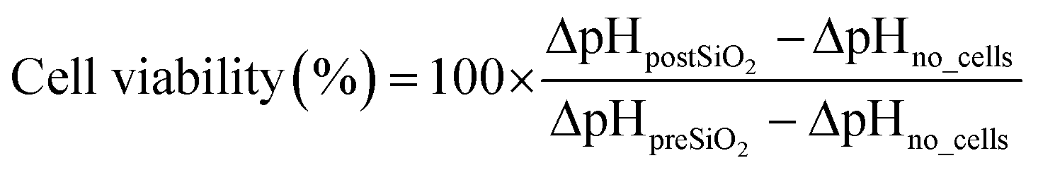
Prior to nanotoxicological experiments, the COC microfluidic prototypes were sealed with micro plugs (Hard Tubing Connector, Micro Fluid Connector, and Micro Plug, ThinXXS) and sterilized for 30 minutes using UV light. Microfluidic ports and tubing were sterilized in 70% ethanol before connection to the chip, followed by extensive rinsing with PBS (Sigma Aldrich). Before cell seeding, the chip was coated with 5% collagen type I (Sigma-Aldrich) solution for 1 hour at 37 °C and rinsed with sterile PBS (Sigma Aldrich). The heated microscope plate was set at 37 °C, and the microfluidic chip was connected to either cell culture medium or nanoparticle solutions (15 mL and 50 mL, Falcon, Fisher-Scientific) located and preconditioned inside a desktop incubator (37 °C). The cell culture medium that was used during on-chip cultivation (until nanotoxicological assessment) was supplemented with 0.5% 2-[4-(2-hydroxyethyl)-1-piperazinyl]-ethanesulfonic acid (HEPES, Sigma Aldrich). Oxygen and pH monitoring was performed at a sampling frequency of 1 Hz and an LED intensity of 80×. For the calibration of the oxygen sensor spots a two-point calibration at anoxic conditions and air-saturated conditions was performed for one spot at 37 °C in cell culture medium to account for slight environmental changes. This calibration was used for all oxygen sensor spots. Anoxic conditions were established by adding NaSO3, air saturated conditions by shaking the medium right before measurement. To calibrate the pH sensor spots, the signal of each spot was recorded after exposing each chamber with buffers of 8 different pH values ranging from pH 4–10. The cotangents of the measured signal were plotted against the pH values, and the calibration function was obtained by fitting with a Boltzmann sigmoidal equation (as previously described21) in a data analysis program (GraphPad Prism).Following cell seeding (5.5 × 10³ cells per chamber) and an attachment period of three hours, medium perfusion (5 μL min−1) was initiated and maintained for at least 16 hours (e.g., overnight proliferation) before nanoparticle exposure. Time-resolved measurements of the oxygen consumption and acidification rates were conducted sequentially by halting the flow for 5–10 minutes once every hour. OCR (ΔO2) and ECAR (ΔpH) were calculated by employing the following equations:
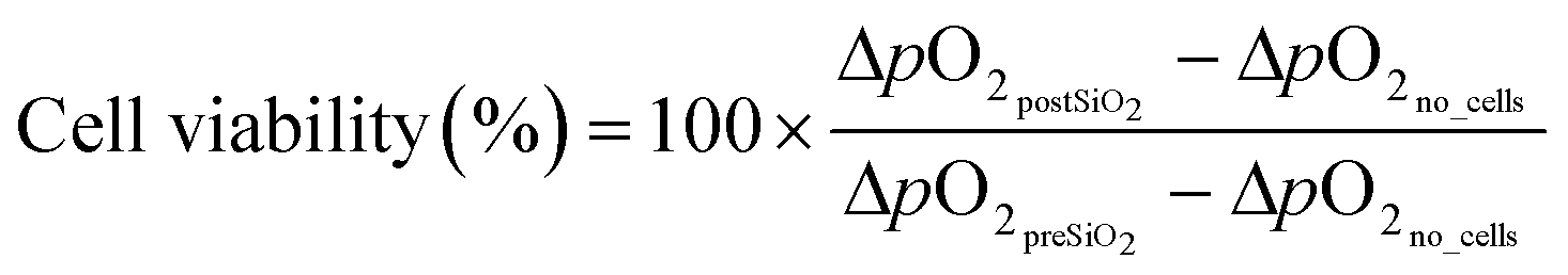
For ΔpO2no_cells and ΔpHno_cells the measured variation in oxygen pressure and pH in chambers without cells during the stop phase was used (n = 3). In total, three recordings were taken during each period to estimate the mean (n = 3) difference in oxygen pressures (referred to as ΔO2 in the result section) before and after exposure to the nanoparticle suspensions. Increasing concentrations of SiO2 nanoparticles in serum-free medium without HEPES at a flow rate of 10 μL min−1 were added for a period of 3 h, and oxygen consumption and acidification rates were monitored. For each cell type, the microfluidic nanotoxicity assessment has been repeated a minimum of 6 times using different passages of cells and batches of microfluidic chips. At the end of each experiment, cell viability was determined employing a LIVE/DEAD® Viability/Cytotoxicity Assay kit (Life Technologies, Vienna, Austria), Hoechst 33258 solution (94403, Sigma Aldrich) and a fluorescent microscope (IX83 Olympus LifeCell). Staining solutions were prepared according to the manufacturer's instructions and incubated for 15 min at 37 °C. Cells were analyzed and counted with the image analysis software Fiji or ImageJ, respectively. In addition, phase-contrast images were taken before and after nanoparticle exposure to assess any impact on cell morphology.
Statistical analysis
Cell viability and extracellular acidification rate data were expressed as mean ± SD or mean ± SEM. The statistical comparisons of means were performed employing a one-way analysis of variance (ANOVA) test using the biostatistical analysis software GraphPad. Significances were depicted as follows: ≤0.0332 (*), ≤0.0021 (**), ≤0.0002 (***). Estimation of the inhibition concentration 50 and 90 (EC50, EC90) was performed using the SigmaPlot software.Results and discussion
From the academic prototype and design optimization to industrial prototyping
As a starting point of our design optimization strategy, a previously published microfluidic chamber design27 (9 × 3 × 0.3 mm per cell culture area 0.22 cm2, 6.6 μL volume) was used to evaluate on-chip luminescence-based oxygen and pH sensing (see Fig. 1) as a novel tool for rapid nanotoxicological assessments. Initial experiments determined the dissolved oxygen distribution within our microfluidic cell culture chambers to estimate dissolved oxygen levels along the 9 mm long confluent cell layers. To monitor oxygen gradients along the entire length of the culture chamber in the presence of increasing flow rates, four oxygen sensor spots were distributed evenly along the flow direction (see Fig. 2A) and alveolar lung cells (A549), known for their high metabolic activities, were used in this study. Results are shown in Fig. 2B, pointing at a clear flow velocity-dependent oxygen distribution along the cell cultivation chamber. In other words, in the presence of lower flow rates such as 2.5 to 5.0 μL min−1, a significant cell-induced oxygen level drop from 160 hPa to 50 hPa or 3.4 fold reduction and 190 hPa 110 hPa or 1.7 fold reduction are apparent between sensor 1 and 4. Continuous cellular oxygen uptake resulted in (a) linear dissolved oxygen gradient along the chamber at 2.5 μL min−1 flow rate, (b) a linear increase of oxygen levels from 160 hPa to 200 hPa at the upstream sensor 1 location in the presence 2.5, 3.0, 4.0, 5.0 and 10 mL min−1 and (c) oxygen saturation (200 hPa) at locations 1, 2 and 3 in the presence of 10 μL min−1. This means that volume flow rates above 10 μL min−1 are needed to ensure comparable (±1.5% variation) oxygen tensions throughout our measurement chambers. As an 11% lower dissolved oxygen level between upstream sensor 1 and downstream sensor 4 was still present even at flow rates of 50 μL min−1 (data not showed), it was concluded that the chamber length needs to be reduced to ensure a homogenous oxygen pressure in the entire chamber. | ||
| Fig. 1 Set-up and working principle of microfluidic nanotoxicological assessment and on-chip luminescence-based oxygen and pH sensing. A) Schematic representation of the main components during the microfluidic nanotoxicological assessment. Cells are seeded through the inlet of the microfluidic chamber to form a confluent monolayer. Light emitted from the FireSting oxygen/pH meter is guided through the optical fibers and excites the oxygen and pH sensors spots located on the upper part of the chamber. The sensor spots generate oxygen and pH concentration-dependent light signals (emission), which are guided back through the optical fibers and detected by the oxygen/pH meter. B) To measure OCR and ECAR, medium perfusion through the chip (Q, 10 μl min−1) was stopped (t0), and the decrease in oxygen pressure and pH within a specific time frame (t1 − t0) was measured, enabling the determination of metabolic rates within a few minutes. OCR (ΔpO2) and ECAR (ΔpH) were measured before cell seeding, after overnight cell adhesion and proliferation, and after three h nanoparticle exposure. After the on-chip nanotoxicological assessment, cell viability was controlled with live/dead staining. | ||
 | ||
| Fig. 2 Characterisation of the oxygen pressure in the microfluidic cell culture chambers. A) Characterisation of the oxygen pressure along microfluidic cell culture chambers in glass prototype. Four oxygen sensor spots were positioned in line along the flow direction to optimize the flow for a homogenous oxygen pressure. B) Measured oxygen gradients in cell culture chamber with a monolayer of A549 cells at different flow rates of medium with flow rates above 10 μl min−1, a homogenous oxygen pressure was obtained in the upper 3/4 part of the chambers (sensor 1–3) while the cells at the lower part never received fully oxygenized medium (sensor 4). | ||
To ensure that the design of the microfluidic device allows for an even distribution of volume flow, a prerequisite for uniform nanoparticle exposure and thus comparability and reproducibility, a CFD simulation was performed (ESI† Fig. S1). A flow velocity of 10 μL min−1 (at the T-junction and cell culture chambers (5 μL min−1)), which was selected based on the initial oxygen distribution experiments, revealed a uniform volume flow suggesting even nanoparticle distribution throughout the chip covering the entire cell culture area. Microfluidic studies employing fluorescently labeled particles were conducted to further support the results obtained by the CFD simulation. As expected, particle distribution throughout the cell culture chamber revealed an even flow as well as particle distribution.
Based on the above results, two minor design optimizations were performed prior to the industrial-relevant prototyping, including the reduction of the cell culture chamber length by 20% (from 9 mm to 7.2 mm) to ensure similar and homogenous oxygen pressure distribution along the entire cell culture area under measurement conditions. In addition, the channel width of the inlets and outlets were narrowed from 1 mm to 0.5 mm to restrict unwanted cell growth in the inlet that may compromise optimal oxygen availability. Moreover, the spatial distance between individual cell culture chambers was adapted to a microtiter plate format (e.g., 9 mm center-to-center). Fig. S1† shows the industrial prototype's final design and dimensions that employ the oxygen impermeable material cycloolefin copolymer (COC). While the microfluidic top layer (total volume of 6 μL), including Mini Luer connectors, sensor grooves, and optical fiber ports, was fabricated using hot embossing technology, a glass microscope slide was bonded to the microfluidic COC layer using an adhesive film ARseal 90880. Fig. 3 depicts the two configurations of the industrial-relevant prototypes where design V1 features additional guiding ports as a simple plug-in system for the optical cables needed for the chemiluminescent oxygen and pH measurements. Oxygen and pH sensors were spotted into the circular grooves before the device assembly. Microfluidic chips were stored in light-impermeable containers before usage up to 24 months without any stability loss, sensor drifts, and a decrease in signal (data not shown).
 | ||
| Fig. 3 Industrial prototype of the microfluidic chip with integrated sensors. A) 3D CAD designs (V1 and V2) of the top layers of the 8-chamber chip, including inlets, fluidic splitter, culture chambers, and outlets. V1 (upper panel) displays integrated holders for the optical fibers. B) Photograph of the manufactured chip, (V1), injection-molded in COC and bonded to a glass substrate. C) Overview of the microfluidic set-up comprised of the microfluidic platform mounted on top of a heated microscope stage. D) A sketch illustrating the integration process of the luminescent sensor spots into the top part of the microfluidic device, as well as a schematic illustrating the working principle of the individual sensor spots. | ||
High sensitivity nanotoxicity assessment based on combined oxygen consumption and extracellular acidification rates
Before on-chip experiments, the cytotoxicity of silicon oxide nanoparticles (SiO2 diameter 25.0 ± 3.66 nm) was characterized using standard static culture plates to determine their suitability as a reference nanomaterial. Initial experiments (see Fig. S3†) show dose–response curves for lung, gut, and endothelial cells using decreasing concentrations of nanosilica (500–250–125–62.5–31.3–15.6 μg mL−1) in the presence and absence of serum protein. This study revealed that a 4-hour exposure in the absence of serum protein is sufficient to induce significant cytotoxic effects, thus confirming the mitigating effect of protein corona at the surface of nanoparticles.34 Interestingly, a significant cell type-dependent shift in MIC values from 9 μg mL−1 to 23 μg mL−1 to 180 μg mL−1 was found for endothelial, lung, and gut cells, respectively. The observed differences in dose–response curves between the selected cell types highlight the importance of including various cell types in nanotoxicological evaluations. Table 1 lists the calculated EC50 values obtained from our nanotoxicology study and compares previously published values. As a result of our pre-screening study, subsequent microfluidic nanotoxicity assessments were conducted using 50 μg mL−1 nanosilica for A549 (used in initial prototype study), 100 μg mL−1 and 500 μg mL−1 for HUVECs as well as 50 μg mL−1 and 500 μg mL−1 for Caco-2 cells.| Cell type | EC50 (μg mL−1) | EC90 (μg mL−1) | EC50 values from literature (μg mL−1, 0% serum) |
|---|---|---|---|
| A549 | 56 (0% serum) | 419 (0% serum) | 50 (60 nm)31 |
| >500 (10% serum) | >500 (10% serum) | ||
| Caco-2 | >500 (0% serum) | >500 (0% serum) | >256 (55 nm)35 |
| >500 (10% serum) | >500 (10% serum) | ||
| HUVEC | 20 (0% serum) | 49 (0% serum) | <50 (ref. 33) |
| 97 (5% serum) | 176 (5% serum) | >200 (20 nm)36 |
Next, the additive effect of nanoparticle perfusion, which has been linked to an increase in nanoparticle uptake and intracellular accumulation, on cytotoxicity was investigated in more detail. In a comparative study, differences in cellular viability among static and dynamic exposure scenarios were evaluated. Viability results using live/dead staining are shown in Fig. S6† and point at increased toxicities in the presence of fluid flow. For instance, a decrease of viability by 13% (50 μg mL−1) and 25% (500 μg mL−1) was observed in the dynamic model compared to the static model for Caco-2 monolayers. In the case of HUVECs, a decrease of 14% (100 μg mL−1) and 25% (500 μg mL−1) was observed for the dynamic exposure scenario compared to the static exposure scheme. Table 2 lists the calculated cell viabilities for each scenario and cell type, as well as a comparison thereof. The modulatory effects of fluid flow on nanotoxicity seen in the current work are in line with previous investigations of our group and other microfluidic studies on uptake and toxicity of nanoparticles for epithelial and endothelial models, where dynamic conditions increase cytotoxicity even for nanoparticle species with low toxicity (e.g., Au nanoparticles).14,37–39 This observation can be explained by a combination of i) increased endocytosis mediated uptake under physiological shear stress as well as ii) an overall higher dosage of nanoparticles at a dynamic exposure scenario compared to a static exposure scheme at the same concentrations.
| Caco-2 | |||
|---|---|---|---|
| NP concentration (0% serum) | Viability static | Viability dynamic | Static vs. dynamic |
| 0 μg mL−1 | 96.8 ± 1% | 98.9 ± 1% | 2.19% |
| 50 μg mL−1 | 90.8 ± 1% | 79.5 ± 9% | −12.45% |
| 500 μg mL−1 | 78.5 ± 1% | 58.8 ± 2% | −25.07% |
| HUVECs | |||
|---|---|---|---|
| NP concentration (5% serum) | Viability static | Viability dynamic | Static vs. dynamic |
| 0 μg mL−1 | 98.7 ± 0.5 | 95.5 ± 3.0 | −3.11% |
| 100 μg mL−1 | 97.5 ± 0.5 | 84.0 ± 6.6 | −13.85% |
| 500 μg mL−1 | 82.9 ± 6.2 | 41.1 ± 14.9 | −50.50% |
The impact of cell type and number on cellular acidification rates was investigated in subsequent experiments using the industrial-relevant prototype to determine optimum assay conditions. In a series of experiments, Caco-2 cells and HUVECs were seeded with increasing seeding densities (1 × 10⁵, 5 × 10⁵, and 1 × 10⁶ cells per mL), and pH shifts were monitored during cell adhesion and spreading processes. Extracellular acidifications rates, expressed as changes in pH, were measured every hour following a 20 min stop of flow. Results shown in Fig. 4A/B reveal a linear decrease in pH values in the presence of increasing Caco-2 and HUVEC cell seeding densities after a 3 h cultivation period. Additionally, luminescence-based pH measurements showed a significantly stronger (3-fold) metabolic activity of Caco-2 cells over HUVECS (see Fig. 4C) already during cell seeding, thus highlighting the ability of integrated microfluidic pH sensing to detect even minor metabolic differences. To determine the minimum assay time needed to identify differences in cellular metabolism, acidification rates are recorded after 3 h post-seeding for every two minutes in the presence of increasing cell numbers. Fig. 4D shows pH shifts induced by the metabolic activity of Caco-2 cells over a period of 20 min resulting in a total ΔpH of 0.13 ± 0.04, 0.56 ± 0.09, 0.845 ± 0.06 after 3 hours of cell adhesion (for 1 × 10⁵, 5 × 10⁵, and 1 × 10⁶ cells per mL, respectively). The above cell densities were selected to achieve either a confluent monolayer of cells (1 × 10⁶ cells per mL), 50% surface coverage (5 × 10⁵ cells per mL) and 10% confluency in the presence of 1 × 10⁵ cells per mL. Similar results were obtained using HUVECs, where a total ΔpH of 0.22 ± 0.02 and 0.37 ± 0.01 was obtained for higher cell densities (see Fig. 4E). In other words, metabolic differences can be readily detected within 10 min during stop-flow conditions (see Fig. 4F). To further investigate whether pH changes can be identified during continuous flow conditions, cellular acidification rates were constantly monitored during nanoparticle exposure. Fig. 5 shows calculated pH values over a period of 1 hour in the absence and presence of increasing nanoparticle concentrations. While measured pH values in control chambers containing no cells but NPs remained stable, the chambers containing monolayers of Caco-2 cells all revealed a time-dependent pH change. While in the absence of nanoparticles, an almost linear pH decrease was evident, chambers perfused with nanoparticle concentrations of 50 μg mL−1 and 500 μg mL−1 revealed lower metabolic activities that decreased over nanoparticle exposure time. Similar results were observed in repeated experiments displaying the same trend for each nanoparticle scenario. Table 3 shows ΔpH presented as the difference in pericellular pH between the start and after 3 h perfusion at a flowrate of 5 μL min−1. Overall, the ability to rapidly obtain information on dynamic cellular metabolic changes in a time-resolved manner further supports the application of acidification rates as a reliable and robust indicator of cell viability. However, to increase the sensitivity of the integrated pH sensor solely, stop-flow measurement conditions are used in all subsequent experiments.
 | ||
| Fig. 4 Impact of cell density and cell type on ECAR. A) Cell number-specific acidification of Caco-2 cells during 3 hours of adhesion. B) Cell number-specific acidification of HUVECs during 3 hours of adhesion. C) Calculated ECAR during 3 hours of adhesion for Caco-2 cells and HUVECs. D) Cell number specific acidification of Caco-2 cells during stop flow phase 4 hours after cell seeding. E) Cell number specific acidification of HUVECs during stop flow phase 4 hours after cell seeding. F) Calculated ECAR during stop flow phase 4 hours after cell seeding for Caco-2 cells and HUVECs. | ||
 | ||
| Fig. 5 Representative graph of extracellular pH in chambers with monolayers of Caco-2 cells during nanoparticle exposure. While in the control chamber (0 μg ml−1), the ECAR of cells is higher than the exchange of new medium, for both chambers exposed to nanoparticles (50 and 500 μg ml−1), a decrease in metabolic rate (increasing pH) is observed, visualizing the toxicological effect of nanoparticles. | ||
| Nanoparticle concentration | ΔpH |
|---|---|
| 0 μg mL−1 | −0.063 ± 0.07 |
| 50 μg mL−1 | 0.288 ± 0.04 |
| 500 μg mL−1 | 1.282 ± 0.25 |
| Medium | 0.018 ± 0.01 |
To finally verify the ability to detect induced metabolic shifts in the presence of 50 μg mL−1 and 500 μg mL−1 nanosilica, in the case of Caco-2 cells as well as 100 μg mL−1 and 500 μg mL−1 nanosilica in the case of HUVECs, oxygen consumption rates, and extracellular acidification were monitored. Fig. 6 shows raw data before and after exposure to silicon oxide nanoparticle suspensions. Oxygen consumption and acidification were recorded in triplicates before cell seeding, after overnight adhesion before nanoparticle exposure, and again after 3 hours of nanoparticles exposure. During the stop-flow measurement period (pump off), an immediate decrease in pericellular oxygen pressure (see Fig. 6G) and extracellular pH (see Fig. 6H) was noticeable for both cell types. In fact, obtained metabolic changes correlated well with obtained cell viabilities using state-of-the-art dye exclusion assays and morphological evaluations using phase-contrast micrographs (see also Fig. S5†). While in the presence of 10 μL min−1 flow rates, oxygen and pH levels remained stable, reduced oxygen depletion rates and pH shifts (see insets) were already detected for Caco-2 cells in the presence of 50 μg mL−1 silica nanoparticles. To evaluate the comparability of on-chip metabolic sensing to standard cell-based nanotoxicological assays, cell viabilities obtained from oxygen, pH sensing, and live/dead staining in the presence of increasing silica oxide nanoparticle concentrations were compared between Caco-2 cells and HUVECs.
 | ||
| Fig. 6 Nanotoxicity assessment after three h perfusion in microfluidic cell culture chambers with different validation methods. A) Cell viability of Caco-2 cells calculated with live/dead staining, oxygen consumption, and acidification rates. B) Cell viability of HUVECs calculated with live/dead staining, oxygen consumption, and acidification rates. C) Fluorescence images of a live/dead assay of Caco-2 cells after 3 hours of nanoparticle exposure. Scale bar: 50 μm. 20× magnification. D) Fluorescence images of a live/dead assay of HUVECs after 3 hours of nanoparticle exposure. Scale bar: 50 μm. 20× magnification. E) Phase-contrast micrographs of Caco-2 cells after (i) over-night proliferation in standard culture medium, (ii) after 3 h perfusion of medium (control), (iii) after 3 h perfusion with 50 μg ml−1 SiO2-NP (arrows depict detaching and disruptions in the cell monolayer) and (iv) and 500 μg ml−1 SiO2-NP (highlighted images present sections of detaching and fragmented cells). Scale bar: 100 μm. 10× magnification. F) Phase-contrast micrographs of HUVECs after (i) over-night proliferation in standard culture medium, (ii) after 3 h perfusion of medium (control), (iii) after 3 h perfusion with 100 μg ml−1 SiO2-NP (inlets display zoomed in picture sections of rounded/detaching cells and apoptotic bodies) (iv) and 500 μg ml−1 SiO2-NP. Scale bar: 100 μm. 10× magnification. Representative graphs of pH and oxygen measurements during stop phase (pump off) and return to the baseline during the flow phase (10 μl min−1) in microfluidic cell culture chambers before and after nanoparticle exposure. The related flow profile is shown under each graph. G) Oxygen consumption of Caco-2 cells measured in three different chambers with increasing nanoparticle concentration (green lines: before nanoparticle exposure, orange lines: after nanoparticle exposure). H) Extracellular acidification of Caco-2 cells measured in three different chambers with increasing nanoparticle concentration (green lines: before nanoparticle exposure, orange lines: after nanoparticle exposure). | ||
Results in Fig. 6G/H not only show a dose-dependent viability decrease in the presence of increasing nanosilica concentrations but also highlight the similarity of calculated%-viability values. For instance, viability of Caco-2 cells after exposure to a nanoparticle concentration of 50 μg mL−1 decreased to 79.5 ± 8.9% (live/dead), 79.4 ± 6.1% (oxygen consumption rates), and 77.1 ± 9.2% (extracellular acidification rates). In the presence of 500 μg mL−1 nanoparticles cell viability decreased to 58.8 ± 2.4% (live/dead), 52.3 ± 5.2% (oxygen consumption), and 58.9 ± 2.7% (acidification). Similar comparability was found using HUVECs where 3 h exposure to 100 μg mL−1 nanoparticles resulted in a cell viability decrease to 84.0 ± 6.6% (live/dead), 81.6 ± 6.3% (oxygen consumption), and 79.7 ± 4.3% (acidification), respectively, while 500 μg mL−1 concentration revealed a viability of 41.1 ± 14.9% (live/dead), 37.6 ± 11.6% (oxygen consumption), and 36.1 ± 11.6% (acidification).
In fact, data analysis (see Fig. S4†) has shown that by using this sensor-based microfluidic analysis approach, cellular viabilities can be readily detected after 20 seconds, resulting in a 90–720× reduction in assay time, compared to conventional viability assays. Examples from live/dead staining images after nanoparticle exposure are depicted in Fig. 6C (Caco-2) and D (HUVECs). It is also important to note that microfluidic culture conditions, including the assay protocol, did not have a significant adverse effect on cell viabilities since control measurements yielded viabilities around 100 ± 5%. Since morphological evaluations are also routinely conducted to assess adverse effects of nanoparticles, phase-contrast images are also provided in Fig. 6E/F. As an example, before NP-perfusion, Caco-2 cells formed a confluent monolayer exhibiting a cobblestone morphology typical of epithelial cells (Fig. 6Ei), which changed following the exposure to 50 and 500 μg mL−1 nanoparticles, wherein Caco-2 cells displayed a disrupted monolayer, detaching as well as fragmented cells (Fig. 6Eiv). Similar morphological changes were observed in HUVECs, which initially showed elongated cells (Fig. 6Fi), leading to rounded cell morphology, characteristic for detaching cells, as well as indications of cellular fragmentation (Fig. 6Fiii). After exposure with the highest concentration (500 μg mL−1), cell density reduction, irregular shape, and cellular shrinkage (apoptotic cells) were observed (Fig. 6Fiv).
Conclusions
In the current work, we have developed an industry-compatible microfluidic multi-sensor integrated prototype to accelerate the transition from academic prototyping to large-scale production of next-generation microfluidic systems containing integrated optical microsensors. It is essential to highlight that a wide range of academic prototypes can either not be fabricated by large-scale microfluidic producers or need significant re-engineering, thus resulting in long development times and accumulation of costs. This academic–industrial development gap can primarily be associated with the different materials and methods, including design specifications used for rapid prototyping in academic and industrial settings. While academic prototyping moves from soft lithography using PDMS to 3D printing technologies, industrial manufacturers are still limited to hot embossing and injection molding using thermoplastic polymers (e.g., COC, PMMA, PE). This means that material choice and properties, as well as manufacturable aspect ratios, wall angles, and other features, are predefined by industrial standards.We have employed a two-step engineering strategy to reduce the overall microfluidic development time needed to go from academic prototyping to industrial prototypes to piloting to mass production. While in the first step, xurography is used to optimize geometries of the microfluidic network, two injection-molded substrates using COC are fabricated in a second step to produce industrial-relevant prototypes. Although device assembly, surface modification, and sensor integration are still performed manually, a medium number (above 100) of fully functional biochips can be readily built and tested prior to a final design freeze needed for large-volume production using automated assembly streets. In our study, we demonstrated the ability to non-invasively monitor cellular metabolic activities, including oxygen consumption and acidification rates, in real-time using our industrial-relevant prototypes. Our results show that oxygen consumption and extracellular acidification rates linearly depend on increasing cell densities but significantly differ between cell types featuring higher (e.g., cancer cells) or lower (e.g., primary cells) metabolic activities. In a final practical application, our dual-sensing microfluidic platform was used to reliably and reproducibly determine the cytotoxicity of SiO2 nanoparticles on epithelial (Caco-2) and endothelial (HUVEC) cells. Results of our microfluidic nanotoxicological screening study further revealed that rapid, non-invasive monitoring of nanomaterial-biology interactions provides similar outcomes than recommended endpoint cell-based assays using dye-exclusion principles, while significantly reducing assay times by a factor of 90–720×. In summary, the developed chip system is ready to be directly translated into mass production due to the fast and time-efficient prototyping strategy, manufacturability of the industrial-relevant prototypes combined with the easy operation and integration of sensors spots.
Author contributions
HZ, SS, and PE conceived the project, designed the experimental outline, and wrote the manuscript. HZ, SS, TS, and MR performed the microfluidic experiments and analyzed the data. DR and SS conceived and performed finite volume CFD simulations. BM and TM prepared the optical sensors for oxygen and pH biosensing. JK, AW, and MW fabricated and characterized the microfluidic device. YK provided both A549 and Caco-2 cell lines and shared her expertise in cellular handling. All authors contributed to and revised the final manuscript.Conflicts of interest
There are no conflicts to declare.Acknowledgements
This work was funded by the Austrian Research Promotion Agency (FFG; 869173), by the European Union's Marie Skłodowska-Curie Action (823981) and by the Fonds National de la Recherche (FNR) Luxembourg in the M-era Net project NanoPD (INTER/MERA/17/11760144). The authors acknowledge the TU Wien University Library for financial support through its Open Access Funding Program. Schematics were created using http://BioRender.com.Notes and references
- C. A. Silvera Batista, R. G. Larson and N. A. Kotov, Science, 2015, 350, 1242477 CrossRef PubMed.
- C. E. Carlton, L. Rabenberg and P. J. Ferreira, Philos. Mag. Lett., 2008, 88, 715–724 CrossRef CAS.
- S. Moeinzadeh and E. Jabbari, in Springer Handbook of Nanotechnology, Springer, Berlin, Heidelberg, 2017, pp. 335–361 Search PubMed.
- M. Orazizadeh, A. Khodadadi, V. Bayati, S. Saremy, M. Farasat and L. Khorsandi, Cell J., 2015, 17, 412–421 Search PubMed.
- G. Pinget, J. Tan, B. Janac, N. O. Kaakoush, A. S. Angelatos, J. O'Sullivan, Y. C. Koay, F. Sierro, J. Davis, S. K. Divakarla, D. Khanal, R. J. Moore, D. Stanley, W. Chrzanowski and L. Macia, Front. Nutr., 2019, 6 DOI:10.3389/fnut.2019.00057.
- M. S. Olson and P. L. Gurian, J. Nanopart. Res., 2012, 14, 786 CrossRef.
- J. S. Qianjun He, Z. Zhang, F. Gao and Y. Li, Small, 2011, 7, 271–280 CrossRef.
- C. Pisani, E. Rascol, C. Dorandeu, J. Gaillard, C. Charnay, Y. Guari, J. Chopineau, J. Armengaud, J.-M. Devoisselle and O. Prat, PLoS One, 2017, 12, e0182906 CrossRef.
- H. M. Braakhuis, S. K. Kloet, S. Kezic, F. Kuper, M. V. D. Z. Park, S. Bellmann, M. Van Der Zande and S. Le, Arch. Toxicol., 2015, 89, 1469–1495 CrossRef CAS PubMed.
- S. K. Kloet, PhD, Wageningen University, 2016 Search PubMed.
- F. Sambale, F. Stahl, F. Rüdinger, D. Seliktar, C. Kasper, D. Bahnemann and T. Scheper, J. Nanomater., 2015, 2015, 1–16 Search PubMed.
- S. K. Mahto, T. H. Yoon, H. Shin and S. W. Rhee, Biomed. Microdevices, 2009, 11, 401–411 CrossRef CAS PubMed.
- S. K. Mahto, T. H. Yoon and S. W. Rhee, Biomicrofluidics, 2010, 4, 034111 CrossRef PubMed.
- V. Charwat, I. Olmos Calvo, M. Rothbauer, S. R. A. Kratz, C. Jungreuthmayer, J. Zanghellini, J. Grillari and P. Ertl, Anal. Chem., 2018, 90, 3651–3655 CrossRef CAS.
- S. K. Mahto, V. Charwat, P. Ertl, B. Rothen-Rutishauser, S. W. Rhee and J. Sznitman, Nanotoxicology, 2015, 9, 381–395 CrossRef CAS PubMed.
- L. Richter, V. Charwat, C. Jungreuthmayer, F. Bellutti, H. Brueckl and P. Ertl, Lab Chip, 2011, 11, 2551–2560 RSC.
- V. Charwat, M. Purtscher, S. F. Tedde, O. Hayden and P. Ertl, Lab Chip, 2013, 13, 785–797 RSC.
- V. Charwat, M. Rothbauer, S. F. Tedde, O. Hayden, J. J. Bosch, P. Muellner, R. Hainberger and P. Ertl, Anal. Chem., 2013, 85, 11471–11478 CrossRef CAS.
- P. Ebbesen, K. U. Eckardt, F. Ciampor and E. O. Pettersen, Acta Oncol., 2004, 43, 598–600 CrossRef CAS.
- J. C. Owicki and J. Wallace Parce, Biosens. Bioelectron., 1992, 7, 255–272 CrossRef CAS PubMed.
- B. Müller, P. Sulzer, M. Walch, H. Zirath, T. Buryška, M. Rothbauer, P. Ertl and T. Mayr, Sens. Actuators, B, 2021, 334, 129664 CrossRef.
- W. W. Robert Landsiedel, L. Ma-Hock, A. Kroll, D. Hahn, J. Schnekenburger and K. Wiench, Adv. Mater., 2010, 22, 2601–2627 CrossRef.
- B. Ekwall, V. Silano and F. Zucco, Short-Term Toxic. Tests Non-Genotoxic Eff., 1990, vol. 7, pp. 75–98 Search PubMed.
- P. G. Jeelani, P. Mulay, R. Venkat and C. Ramalingam, Silicon, 2020, 12, 1337–1354 CrossRef CAS.
- S. R. A. Kratz, C. Eilenberger, P. Schuller, B. Bachmann, S. Spitz, P. Ertl and M. Rothbauer, Sci. Rep., 2019, 9, 1–12 CAS.
- D. A. Ferreira, M. Rothbauer, J. P. Conde, P. Ertl, C. Oliveira and P. L. Granja, Adv. Sci., 2021, 8(8), 2003273 CrossRef CAS.
- H. Zirath, M. Rothbauer, S. Spitz, B. Bachmann, C. Jordan, B. Müller, J. Ehgartner, E. Priglinger, S. Mühleder, H. Redl, W. Holnthoner, M. Harasek, T. Mayr and P. Ertl, Front. Physiol., 2018, 9, 1–12 Search PubMed.
- J. Ehgartner, P. Sulzer, T. Burger, A. Kasjanow, D. Bouwes, U. Krühne, I. Klimant and T. Mayr, Sens. Actuators, B, 2016, 228, 748–757 CrossRef CAS.
- J. Y. Tinevez, N. Perry, J. Schindelin, G. M. Hoopes, G. D. Reynolds, E. Laplantine, S. Y. Bednarek, S. L. Shorte and K. W. Eliceiri, Methods, 2017, 115, 80–90 CrossRef CAS.
- S. Peter, D. Sticker, M. Rothbauer, S. Lechner, M. Hehenberger and P. Ertl, Lab Chip, 2015, 15, 4542–4554 RSC.
- I.-L. H. Annika Mareike Gramatke, J. Nanomed. Nanotechnol., 2014, 05(06), 1000248 Search PubMed.
- L. Armand, A. Tarantini, D. Beal, M. Biola-Clier, L. Bobyk, S. Sorieul, K. Pernet-Gallay, C. Marie-Desvergne, I. Lynch, N. Herlin-Boime and M. Carriere, Nanotoxicology, 2016, 10, 913–923 CrossRef CAS PubMed.
- J. Duan, Y. Yu, Y. Li, Y. Yu, Y. Li, X. Zhou, P. Huang and Z. Sun, PLoS One, 2013, 8, e62087 CrossRef CAS.
- A. Lesniak, F. Fenaroli, M. P. Monopoli, C. Åberg, K. A. Dawson and A. Salvati, ACS Nano, 2012, 6, 5845–5857 CrossRef CAS PubMed.
- A. Tarantini, R. Lanceleur, A. Mourot, M. T. Lavault, G. Casterou, G. Jarry, K. Hogeveen and V. Fessard, Toxicol. In Vitro, 2015, 29, 398–407 CrossRef CAS.
- X. Liu and J. Sun, Biomaterials, 2010, 31, 8198–8209 CrossRef CAS.
- M. Rothbauer, I. Praisler, D. Docter, R. H. Stauber and P. Ertl, Biosensors, 2015, 5, 736–749 CrossRef CAS.
- A. Oddo, M. Morozesk, E. Lombi, T. B. Schmidt, Z. Tong and N. H. Voelcker, Nanoscale Adv., 2021, 3, 682–691 RSC.
- V. Raghavan, Y. Rbaibi, N. M. Pastor-Soler, M. D. Carattino and O. A. Weisz, Proc. Natl. Acad. Sci. U. S. A., 2016, 113, E1587 CrossRef.
- E. Tanumihardja, R. H. Slaats, A. D. Van Der Meer, R. Passier, W. Olthuis and A. Van Den Berg, ACS Sens., 2021, 6, 267–274 CrossRef CAS.
- S. A. M. Shaegh, F. De Ferrari, Y. S. Zhang, M. Nabavinia, N. B. Mohammad, J. Ryan, A. Pourmand, E. Laukaitis, R. B. Sadeghian, A. Nadhman, S. R. Shin, A. S. Nezhad, A. Khademhosseini and M. R. Dokmeci, Biomicrofluidics, 2016, 10(4), 044111 CrossRef.
- K. S. Lee, P. Boccazzi, A. J. Sinskey and R. J. Ram, Lab Chip, 2011, 11, 1730–1739 RSC.
- A. Weltin, K. Slotwinski, J. Kieninger, I. Moser, G. Jobst, M. Wego, R. Ehret and G. A. Urban, Lab Chip, 2014, 14, 138–146 RSC.
- S. H. Huang, K. S. Huang and Y. M. Liou, Microfluid. Nanofluid., 2017, 21(1) DOI:10.1007/s10404-016-1841-z.
Footnotes |
| † Electronic supplementary information (ESI) available. See DOI: 10.1039/d1lc00528f |
| ‡ These authors contributed equally. |
| This journal is © The Royal Society of Chemistry 2021 |