
Programmable chiral states in flocks of active magnetic rollers†
Koohee
Han
 * and
Alexey
Snezhko
* and
Alexey
Snezhko
Materials Science Division, Argonne National Laboratory, Lemont, IL 60439, USA. E-mail: hank@anl.gov
First published on 19th November 2020
Abstract
Inspired by nature, active matter exemplified by self-organization of motile units into macroscopic structures holds great promise for advanced tunable materials capable of flocking, shape-shifting, and self-healing. Active particles driven by external fields have repeatedly demonstrated potential for complex self-organization and collective behavior, yet how to guide the direction of their collective motion largely remains unexplored. Here, we report a system of microscopic ferromagnetic rollers driven by an alternating magnetic field that demonstrates programmable control of the direction of a self-organized coherent vortical motion (i.e., chirality). Facilitated by a droplet confinement, the rollers get synchronized and display either right- or left-handed spontaneous vortical motion, such that their moving direction determines the vortex chirality. We reveal that one can remotely command a flock of magnetic rollers to switch or maintain its chiral state by modulating a phase shift of the sinusoidal magnetic field powering the active rollers. Building on our findings, we realize a self-assembled remotely controlled micro-pump architecture capable of switching the fluid transport direction on demand. Our studies may stimulate new design strategies for directed transport and flocking robotics at the microscale based on active colloids.
Introduction
Active matter, which deals with physical systems composed of large numbers of motile units, is a rapidly growing field pushing the boundaries of conventional materials.1–3 Their out-of-equilibrium spatiotemporal patterns inspire new “bottom-up” design strategies for the next generation of tunable materials capable of flocking, shape-shifting, and self-healing.4–8 Advances in multidisciplinary science and technology across chemistry, physics, biology, materials science, and engineering have enabled the development of a wide variety of active (or self-propelling) microscopic units that convert energy from their environment into directed motion.9–12 Field-driven active colloids constitute a promising platform to investigate an emergent collective behavior in a group of active particles given their ability to self-propel and self-organize in response to external stimuli.13–15 Despite the simplicity of the constituent colloidal particles, when driven out of equilibrium, they can display a rich diversity of self-organized dynamic states depending on the types of particle designs and/or external fields, ranging from self-assembled asters,16 spinners,17–19 carpets,20,21 arrays22,23 and swarms24–26 to living crystals,27 unstable densification fronts,28 and odd chiral surface flows.29The key to making active tunable materials is the control of local communication between motile units and on-demand manipulation of their collective patterns.18,30,31 Active colloidal rollers, driven by local torques, have attracted a lot of attention because of the ease of tuning the activity and dynamic self-organization in these systems by manipulation of the energizing field parameters.32,33 At present, two physical mechanisms are available to generate these rollers: 1) an electric torque exerted on a dielectric particle in a conductive fluid under a static electric field (the Quincke rotation),34,35 and 2) a magnetic torque experienced by a ferromagnetic particle in a uniaxial alternating magnetic field.36,37 Because of single axis field excitation perpendicular to the substrate interface, both mechanisms do not prescribe the direction of particle rolling motion but allow a group of rollers to locally communicate through alignment interactions and determine the moving direction on their own. Active rollers driven by these mechanisms have proven to successfully execute reversible self-organized pattern transformations between gas, flock, and coherent vortex states that could potentially be useful for microbotic applications.15,32
To extract useful work from active matter, one needs to learn how to control and guide the global direction of their collective motion.38 Significant effort has been dedicated to rectify active matter's complex spatiotemporal flocking into directional motion, which can be classified into two major approaches. The first approach is to introduce global gradients where active units spontaneously move toward or away from the gradient source.39–41 Such phenomena are known as taxis or tactic motion,42–46 which can also be often found in nature such as bacteria seeking nutrients and insects flying toward light sources at night. The second approach is to introduce global confinements where active units coherently move along confining patterns or inside confining boundaries.47–50 Yet, an outstanding challenge in command of active matter is to control and guide the global direction of coherent spontaneous vortical motion. This requires to take control of all the individual particles while retaining their autonomy, which can't be implemented by the above two approaches. We note that externally applied global rotating magnetic fields have been used to generate and control the vortex structures of magnetic particles, acting as microbotic swarms.25,26 However, the global rotating fields prescribe the particles' motion direction along the rotation axis and limit their degrees of motion freedom. In comparison, motile units, whose direction of motion is not prescribed by a global field, can spontaneously develop a coherent vortical motion with chirality selected by the system.51–54
One of the most widely used approaches for a generation of active vortex structures often relies on a confinement. A concentrated suspension of motile bacteria, for example, can self-organize into a single-vortex state by a circular confinement55,56 and a multi-vortex state by a periodic array of geometrical confinement.57–59 Notably, the coupling of neighboring macroscopic vortices in the multi-vortex state provides a means of controlling the relative vortex–vortex ordering (e.g., anti-ferromagnetic order). However, it has long been believed that the direction of coherent vortical motion (i.e., chirality) inside of each independent active vortex is randomly determined.53,55,56,60 Since an active vortex structure acts as a macroscopic dynamic entity with potential to interact with other vortex structures, passive materials, and the surrounding environment,60 on-demand switching of the vortex chirality is of fundamental interest and may open new opportunities in microscale mixing and transport applications.
In this paper, we report an approach for controlling the chirality of spontaneously self-organized vortex states in ensembles of active magnetic rollers. The rollers, confined inside immobile water droplets, are energized by a uniaxial alternating current (AC) magnetic field. The energized rollers spontaneously start to move coherently and form either clockwise or counterclockwise vortical states inside the droplet such that their moving direction determines the vortex chirality. We reveal that the global rotational direction of the self-organized vortex can be controlled on-demand by a temporal modulation of the phase shifts of the driving magnetic field. Building on our findings, we demonstrate a programmable control of a spontaneous vortex chirality formed by magnetic micro-rollers and its possible application as a remotely controlled micro-pump.
Experimental section
Experimental setup
A water droplet (diameter 2–4 mm) at the bottom surface of a flat Petri dish (Corning; diameter 100 mm and height 15 mm) was placed in the middle of two custom made precision Helmholtz coils (diameter 130 mm) separated by 70 mm. The water droplet contained ferromagnetic nickel (Ni) microparticles (Alfa Aesar; diameter 125–150 μm) where the magnetic moment per particle is μ ≃ 2 × 10⁻⁵ emu. A scaled view of the experimental setup (Fig. S1†), magnetic hysteresis curve (Fig. S2†), and characteristic time-scales for the responsiveness of the Ni particles are provided in the ESI.† The pair of coils was used to energize the system by generating an uniaxial alternating current magnetic field with an amplitude of 35 Gauss applied perpendicular to the surface. The container was housed on a microscope stage (Leica MZ9.5) where the dynamics of the particles was monitored by means of a fast CMOS camera (iNS1, Integrated Design Tools, Inc.) at a frame rate of 50–100 frames per s.Pump device fabrication
A Petri dish was masked using patterned polydimethylsiloxane (PDMS; SYLGARD™ 184 Silicone Elastomer Kit, Dow Inc.) and selectively hydrophilized through the patterned PDMS mask using a corona treater (BD-10A, Electro-Technic Products Inc.). Then, a water suspension of Ni particles was spread out only on the pre-defined hydrophilic pattern with a pump device design. Schematics of these procedures and design guidelines are provided in the ESI† (Fig. S3).Data analysis
To investigate the dynamics of the magnetic rollers, image sequences were analyzed. Particle tracking was performed by a MATLAB script based on the Crocker and Grier algorithm61 to identify the 2D location of each roller. The xy-coordinates of the rollers in consecutive image sequences were used to characterize the roller velocity and the polar order parameter in the system.Results and discussion
Magnetic field-driven vortex emergence and chirality switching
The experimental system consists of ferromagnetic Ni spheres (125–150 μm) confined inside a water droplet placed on a solid surface in the xy-plane and energized by a uniaxial AC magnetic field applied perpendicular to the surface of the substrate (Fig. 1a and b). We apply a sinusoidal magnetic field along the z-axis, Hz = H0![[thin space (1/6-em)]](https://www.rsc.org/images/entities/char_2009.gif) sin(2πft + δ), where H0 is the field amplitude (35 Gauss unless otherwise stated), f is the field frequency, and δ is a phase shift (see Experimental section for details). The Ni spheres spontaneously break the uniaxial symmetry of the driving magnetic field and turn into active rollers with no prescribed direction in the xy-plane in a certain range of the magnetic field parameters.36 Briefly, a Ni sphere exhibits stationary, oscillation, steady rotation, and chaotic regimes depending on the inertia contribution where the dynamics transition between the 4 regimes can be implemented by tuning f. We specifically focus on the steady rotation regime (f = 20–40 Hz) in which the following condition is satisfied:36Im(ν[−p2, 2q]) − p > 0. Here, the Mathieu characteristic exponent, ν, is a function of p = αr/(2πfI) and q = μH0/[(2πf)2I] where αr, μ, and I are, respectively, the rotational drag coefficient, magnetic moment, and moment of inertia of the particle. In the steady rotation regime, the presence of a solid surface in the proximity of a spinning particle results in the rolling motion.33,62,63 Particle inertia plays a key role in the emergence of a spinning motion of a magnetic sphere in a uniaxial field, and it constitutes an important distinction of this system from other torque-driven particles such as Quincke rollers or particles energized by rotating fields. Magnetic rollers rotate in synchrony with the periodic change in the direction of the alternating magnetic field, and the speed of their rolling motion is determined by the field frequency rather than by the field amplitude.36,60,64 When these magnetic rollers are far apart from each other, they exhibit a directionally uncorrelated motion. In contrast, when they come close enough to synchronize themselves through magnetic and hydrodynamic interactions, the rollers display a transition to a coherent motion as observed in the emergence of magnetic roller vortices in an unconfined environment.54,60
sin(2πft + δ), where H0 is the field amplitude (35 Gauss unless otherwise stated), f is the field frequency, and δ is a phase shift (see Experimental section for details). The Ni spheres spontaneously break the uniaxial symmetry of the driving magnetic field and turn into active rollers with no prescribed direction in the xy-plane in a certain range of the magnetic field parameters.36 Briefly, a Ni sphere exhibits stationary, oscillation, steady rotation, and chaotic regimes depending on the inertia contribution where the dynamics transition between the 4 regimes can be implemented by tuning f. We specifically focus on the steady rotation regime (f = 20–40 Hz) in which the following condition is satisfied:36Im(ν[−p2, 2q]) − p > 0. Here, the Mathieu characteristic exponent, ν, is a function of p = αr/(2πfI) and q = μH0/[(2πf)2I] where αr, μ, and I are, respectively, the rotational drag coefficient, magnetic moment, and moment of inertia of the particle. In the steady rotation regime, the presence of a solid surface in the proximity of a spinning particle results in the rolling motion.33,62,63 Particle inertia plays a key role in the emergence of a spinning motion of a magnetic sphere in a uniaxial field, and it constitutes an important distinction of this system from other torque-driven particles such as Quincke rollers or particles energized by rotating fields. Magnetic rollers rotate in synchrony with the periodic change in the direction of the alternating magnetic field, and the speed of their rolling motion is determined by the field frequency rather than by the field amplitude.36,60,64 When these magnetic rollers are far apart from each other, they exhibit a directionally uncorrelated motion. In contrast, when they come close enough to synchronize themselves through magnetic and hydrodynamic interactions, the rollers display a transition to a coherent motion as observed in the emergence of magnetic roller vortices in an unconfined environment.54,60
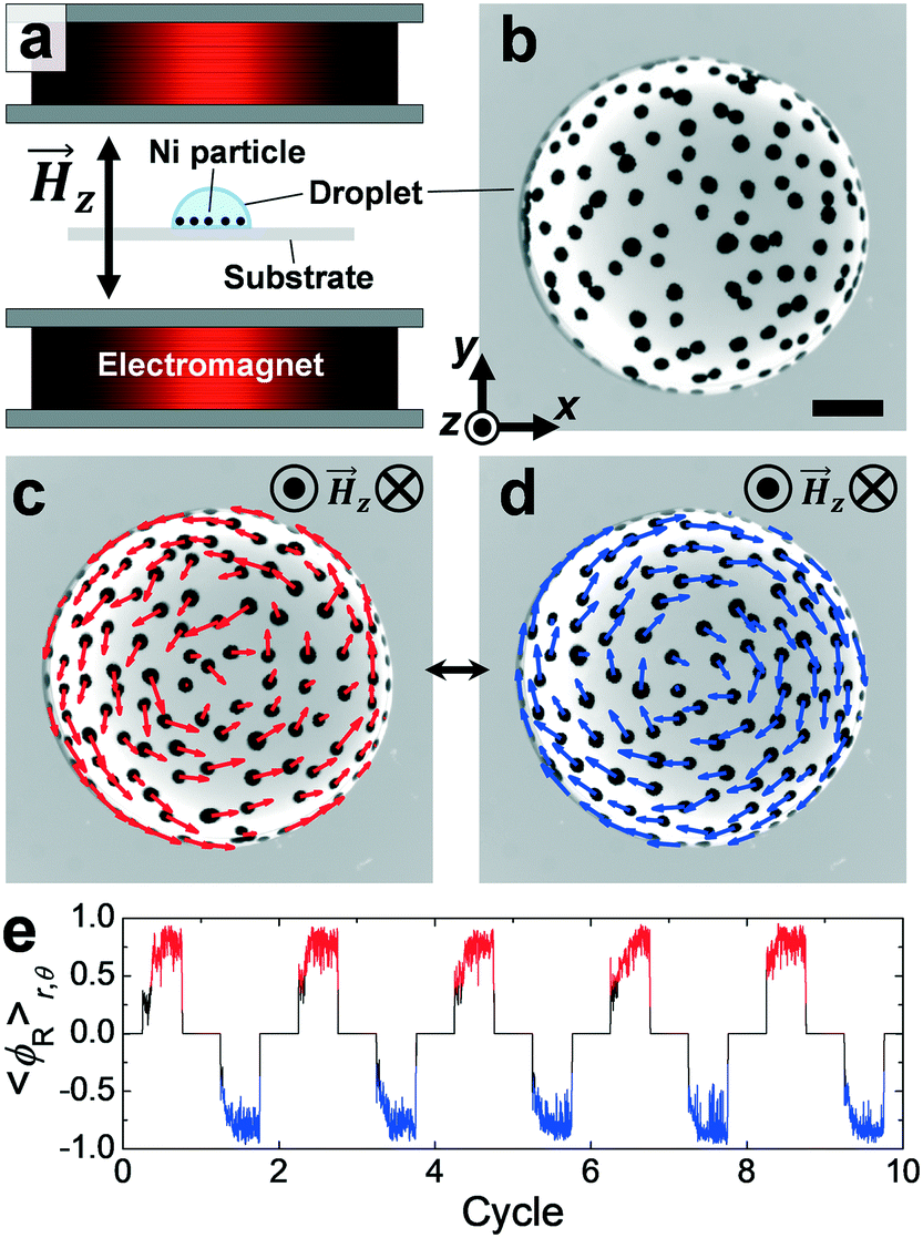 | ||
| Fig. 1 Magnetic field-driven formation of a magnetic roller vortex capable of chirality switching. (a) Schematic illustration of the experimental setup (not to scale; a scaled view in Fig. S1†). A pair of electromagnetic coils was used to generate a sinusoidal AC magnetic field applied perpendicular to the water droplet/substrate interface. Ni particles are sedimented inside a water droplet (side view). (b) A snapshot of a dispersion of the Ni particles confined inside a water droplet placed on the substrate in the absence of the field (top view). The xyz-coordinate system is denoted on the left bottom of the snapshot. The scale bar is 0.5 mm. (c and d) An emergent vortex from the Ni spheres in the presence of the field (top view). The self-organized magnetic rollers exhibit right- (c) and left-handed (d) vortical motion in which the arrows indicate the actual moving direction of the rollers, retrieved from single-particle tracking. A phase shift δ = π in the sinusoidal magnetic field allows the reversible transition between the (c) and (d) states. (e) The time evolution of the mean polar order parameter in the vortex, 〈ϕR〉r,θ, for 10 discrete cycles (see Movie S1†). 〈ϕR〉r,θ values higher than 0.5 and lower than −0.5 represent the vortex state with right- and left-handedness, respectively. | ||
In the present model system, we confine the magnetic rollers inside a water droplet to induce a stable vortex in a reproducible manner. The magnetic particles inside the droplet form a vortex within a few seconds upon application of the sinusoidal AC magnetic field with f = 40 Hz. As shown in Fig. 1c and d, the rollers self-organize and display either clockwise or counterclockwise vortical motion visualized by means of single-particle tracking (see Experimental section for details). To quantify the vortex state, we calculate the mean polar order parameter, 〈ϕR〉:
 | (1) |
Onset conditions of a self-organized roller vortex
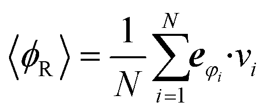
To find an optimal condition for the formation of a self-organized roller vortex in a droplet confinement, we performed a systematical investigation on the onset of the globally correlated state as a function of the field frequency, f, and the particle number density, ρ. The results are summarized in Fig. 2. The frequency is a convenient knob to control the rollers' activity by tuning the roller-to-roller correlations. In the steady rotation regime (f = 20–40 Hz), the rotation of a magnetic particle is synchronous with the external magnetic field. Naturally, within this regime, a higher-frequency field leads to a faster rolling motion of the particle, which allows higher roller-to-roller velocity correlations; field amplitude, on the other hand, does not affect the rolling speed36 of the rollers. While the rollers display a gas phase at 20 Hz because of low roller-to-roller correlations, they form a flocking phase at about 30 Hz and a globally correlated vortex state at around 40 Hz. Frequencies close to 40 Hz correspond to a maximal sustainable steady speed of the rollers and as a result largest velocity spatial correlations in the ensemble.36 Above 40 Hz, more and more particles cannot sustain a steady rolling motion (due to magnetic moment de-pining inside the particles and increasing role of the lift force leading to temporal departures of the rollers from the interface and loss of their rolling speeds33). At low activity levels (f = 20 Hz), magnetic rollers are in the gas state at both low (Fig. 2a, left) and high (Fig. 2b, left) particle densities due to low roller-to-roller correlations. As the activity increases (f = 40 Hz), the system develops flocks and then finally a vortex state sets up in the whole system (see Fig. 2a, right and b, right). As demonstrated by the evolution of the polar order parameter, 〈ϕR〉r,θ, depending on f, the optimal condition for the vortex corresponds to f = 40 Hz (the highest attainable roller-to-roller correlations) (see Fig. 2c and Movie S2†). Once at optimal activity levels, the global vortex state is robust in a wide range of ρ as illustrated in Fig. 2d.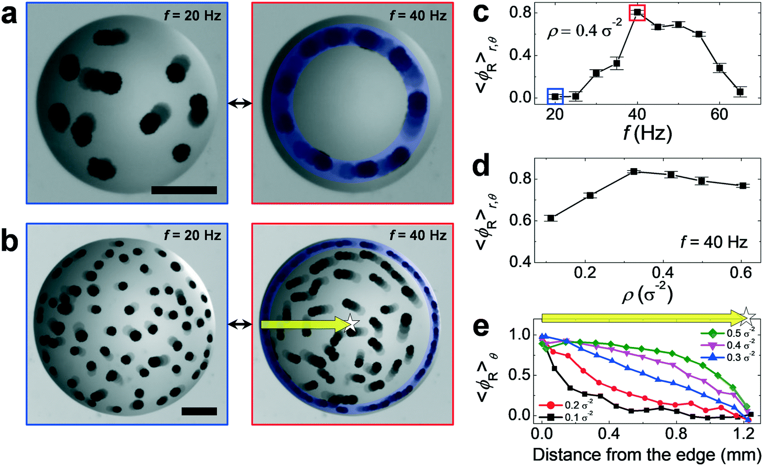 | ||
| Fig. 2 Emergence of the magnetic roller vortex. (a and b) A reversible transition between the gas and vortex phase in an ensemble of magnetic rollers dictated by the frequency change. Magnetic rollers with low ρ (a) and high ρ (b) in which the rollers show a diffusive motion at f = 20 Hz (left panels) while they display a coherent vortical motion at f = 40 Hz (right panels). Five consecutive images were overlaid in each snapshot to visualize the moving direction of the rollers. The blue annulus indicates the formation of a polar band around the droplet edge. The scale bars are 0.5 mm. (c) 〈ϕR〉r,θ as a function of f at ρ = 0.4σ−2. The blue and red square locate the 〈ϕR〉r,θ value at f = 20 Hz and f = 40 Hz, respectively, in which 〈ϕR〉r,θ at f = 20 Hz (i.e., ≈ 0) represents a gas phase while 〈ϕR〉r,θ at f = 40 Hz (i.e., ≈ 0.8) represents a vortex phase. (d) 〈ϕR〉r,θ as a function of ρ at f = 40 Hz. 〈ϕR〉r,θ exhibits monotonic increases with ρ until the rollers become so concentrated that they start to aggregate (i.e., ρ > 0.4σ−2) and then slightly decreases with further increase in ρ, but the vortex phase is present at all these ρ. (e) 〈ϕR〉θ as a function of distance from the droplet edge. The yellow arrows in (b, right) and (e) correspondingly start at the droplet edge and end at the droplet center (highlighted by the star symbol). At all ρ, the closer to the droplet edge, the larger the 〈ϕR〉θ value except for ρ > 0.4σ−2 at around the edge due to the aggregation of the rollers. | ||
A closer look at the relative position between the rollers reveals that the propagation of the roller-to-roller synchronization from the droplet edge to the center plays a pivotal role in the emergence of a macroscopic vortical motion. At low ρ and optimal activity (f = 40 Hz) shown in Fig. 2a, right panel, all the rollers get trapped around the droplet edge and keep moving along the circular trajectory (highlighted by the blue annulus) possibly because the presence of a confining elastic border along with the capillary forces at the droplet edge effectively reduces the rotational diffusion of the particles and increases their persistence length.65–68 Due to the increased persistence length, the magnetic rollers exhibit higher moving velocity at the droplet edge compared to the ones at the droplet center (Fig. 1c, d and S4†). At high ρ and f = 40 Hz (Fig. 2b, right), a similar polar band appears and acts as a nucleation site from which the roller-to-roller synchronization propagates towards the droplet center. As a result, the rollers closer to the polar band exhibit a higher degree of alignment synchronization than those in the inner part (Fig. 2b, right). We characterize the alignment synchronization between the rollers with respect to the vortex phase by calculating 〈ϕR〉θ as a function of distance from the droplet edge (see Fig. 2e) where the yellow arrow indicates the corresponding location of the droplet edge and center (shown in Fig. 2b, right). In general, 〈ϕR〉θ decreases from the droplet edge to the center for all ρ. However, at ρ higher than 0.4σ−2, 〈ϕR〉θ around the edge drops a bit due to the aggregation of the magnetic rollers in a concentrated region, which translates to the slight decrease in 〈ϕR〉r,θ (Fig. 2d).
Mechanism of chirality switching in an emergent vortex
Importantly, the onset of spatial and temporal coherence in the self-organized roller vortex at the optimal activity is also correlated with the synchronization of the magnetic moment orientation of the rollers with the phase of the external magnetic field.33,36 Consequently, by manipulations of the magnetic field phase, it should be possible to orchestrate the collective dynamics of the globally correlated roller states, such as a roller vortex. In particular, while the initial chiral state of a roller vortex is randomly selected as the applied field is spatially symmetric along the z-axis with respect to the randomly distributed rollers in the xy-plane, the subsequent chiral states of the vortex can be in principle prescribed by the phase shift of the magnetic field. As a starting point example of such control, we first demonstrate to switch the rotation direction of a single roller (see Fig. 3a and b and Movie S3†). The process behind the controlled reversal relies on the knowledge of the roller's magnetic moment orientation that is resonated with the periodic change in the direction of the external magnetic field. Let's assume that the dipoles of the roller initially point to the left as depicted in the right bottom panel of Fig. 3a. Upon application of the sinusoidal field along the z axis with δ = 0, the roller rotates clockwise and returns back to the initial orientation of the dipoles in one field cycle. Since the roller particle is confined at the droplet edge, the particle acting as a 1D magnetic roller keeps rotating and moving in the same direction along the edge with the repeated cycles of the same signal. If on the other hand, we apply the field with a phase shift δ = π, the rotation of the roller is reversed and the roller propels in the opposite direction as shown in Fig. 3b. Therefore, one can command the roller to reverse or keep the moving direction (Fig. 3a and b) by applying complete cycles of the field signal with or without the phase shift. This on-demand bidirectional tunability in the rolling direction, enabled by the permanent dipoles, is the distinctive feature of the magnetic rollers in contrast to the lack of such tunability in systems based on Quincke rollers whose induced dipole orientation is reset every time an external field is applied.69 | ||
| Fig. 3 Mechanism of chirality switching in the magnetic roller vortex. (a and b) Reversible switching in the moving direction of a single roller (see Movie S3†). The single roller moves clockwise (a) or counterclockwise (b) along the droplet edge: (left panel) an overlay of six consecutive images visualizing the moving direction of the roller; (right top panel) complete cycles of a magnetic field signal applied along the z axis; (right bottom panel) a schematic description of the change in the magnetic dipole orientation of the roller during one complete cycle of the magnetic field signal shown in the right top panel. The xyz-coordinate system is denoted on the right bottom in the snapshot (a, left). The scale bars are 0.2 mm. (c and d) Reversible switching of the chirality in two separated vortices. The two vortices, A and B, exhibit left- and right-handedness (c) or right- and left-handedness (d): (left panel) retrieved from single-particle tracking, the arrows indicate the moving direction of the self-organized synchronized rollers revealing the opposite chirality of the two vortices; (right panel) a schematic description of the change in the magnetic dipole orientation of the synchronized rollers in each vortex during one complete cycle of the magnetic field signal shown in (a, right top) or (b, right top). The introduction of a π phase shift to the driving magnetic field enables reversible transitions (a) ↔ (b) and (c) ↔ (d). The scale bars are 1 mm. (e) A programmable control of the chirality for the two spatially separated vortices (see also Movie S4†). (Top panel) Time evolution of 〈ϕR〉r,θ for the two vortices, A and B, shown in (c) and (d), for 6 discrete cycles. (Bottom panel) The sequence of the applied magnetic signals during the 6 discrete cycles. The vortices A and B simultaneously switch their chirality upon the introduction of the phase shift to the preceding magnetic signal (e.g., cycle 1 → 2) while they maintain their chirality in the absence of the phase shift (e.g., cycle 3 → 4). | ||
This approach can be successfully applied to orchestrate the chiral state of a globally correlated magnetic roller vortex as demonstrated in Fig. 3c and d. As an example, we show two isolated vortices with opposite initial chiralities formed in two separated droplets (Fig. 3c, left). Both vortices are simultaneously driven by the same sinusoidal signal used for the single roller where the magnetic rollers inside of each droplet are spontaneously synchronized (as discussed in Fig. 2 and in ref. 36). Similar to the case of the single roller, the inverted sinusoidal signal applied at time t = n/f (here, n is an integer number) induces the chiral state reversal in both vortices, see Fig. 3d. The vortex chirality can be controlled in a programmable way over a long period of time (see Fig. 3e and Movie S4†). The change in 〈ϕR〉r,θ (Fig. 3e, top) well reflects that two independent vortices simultaneously switch or maintain their chirality in response to the presence or absence of the phase shift in the field signal with respect to the preceding signal (Fig. 3e, bottom). Note that the initial vortex chirality is randomly selected by the system, however the subsequent chiral states are under complete control by the magnetic field command as can be confirmed by the same programmable chirality control executed in two isolated vortices with identical initial chirality (see Movie S5†) (cf., Movie S4†).
Application for switchable micro-pump device
Programmable chiral states of a flock of self-organized rollers could be exploited for control of particle and fluid transport at the microscale. As a proof of concept, we fabricated (see Experimental section and Fig. S3† for the design guidelines) a microscale pump device capable of reversible fluid motion illustrated in Fig. 4. This pump device employs flocking rollers to promote the fluid transport where the rollers circulated on the racetrack region entering and leaving the vortex structure caged in the adjoint circular part of the device. Since the particles rotate in synchrony with the periodic changes in the direction of the alternating magnetic field, the speed of the particle rolling motion is determined by the field frequency rather than by the field amplitude. Accordingly, the pumping speed can be tuned by the moving speed of the rollers controlled by the frequency of the energizing field. The mean velocity of the rollers in the pump, 〈Vp,x〉, increases linearly with f (Fig. 4a), which agrees with the expectations, Vp ∝ 2πrf, where r is the particle radius.36 More importantly, the direction of the fluid motion can be reversed by guiding the rollers to move in the opposite direction using the magnetic phase-shift command described above (Fig. 4b–d; Movie S6†). To visualize the fluid flow generated by the roller vortex pump, a drop of a water-miscible dye was added to the track (Fig. 4b). As the rollers move on the track in a clockwise direction driven by the energizing magnetic field with a sinusoidal signal, they entrain and transport the dye (Fig. 4b and c). After the external field was turned off and the rollers ceased their motion (Fig. 4c), the field with an inverted sinusoidal signal (δ = π) was applied and the direction of the fluid motion was successfully reversed as confirmed by the dyed flow (Fig. 4c and d). We note, however, that fluid reversibility70 is not conserved since our system is not at a low Reynolds number (Re) regime but at a finite Re regime (Re ∼ 2 for the microscopic flow generated by an individual roller, and Re ∼ 10 for the induced macroscopic flow in the micro-pump architecture). Overall, we demonstrate that a flock of active magnetic rollers can be utilized to construct a micro-pump device capable of in situ assembly/disassembly and on-demand fluid direction reversal by remote actuation. These capabilities may enable new approaches for the design of transport and mixing applications at the microscale.71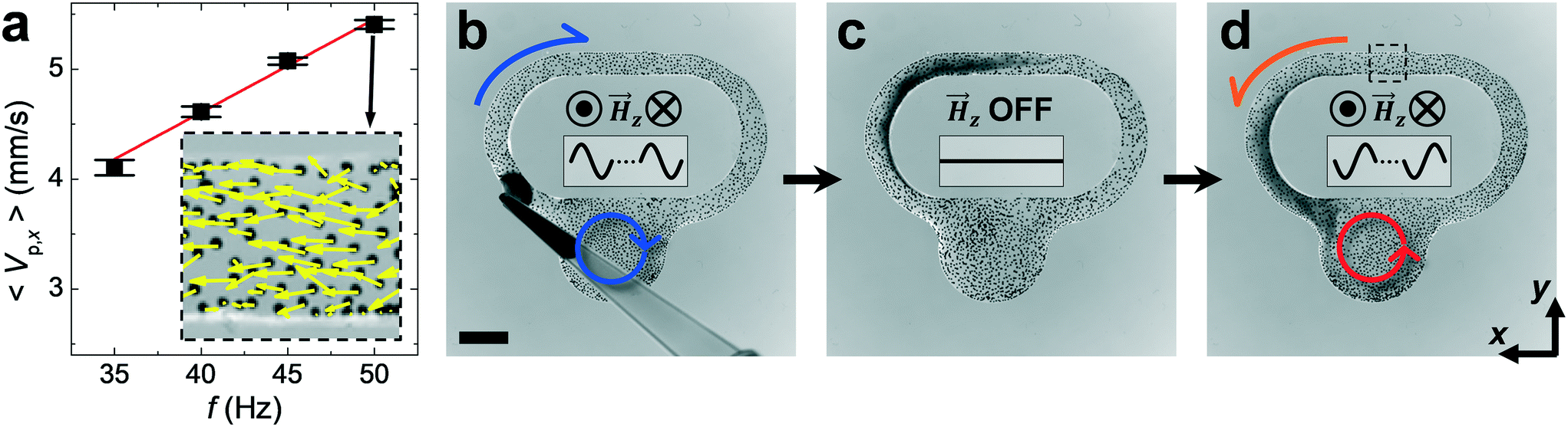 | ||
| Fig. 4 Dynamic micro-pump architecture. (a) The mean velocity of the rollers, 〈Vp,x〉, as a function of f. The 〈Vp,x〉 value was obtained by averaging the x-components of the rollers' velocities calculated inside the square area of the device indicated in (d); 〈Vp,x〉 increases linearly with f. The yellow arrows in the inset visualize the moving directions of the rollers in the square at f = 50 Hz. (b–d) The snapshots demonstrate on-demand reversal of a clockwise/counterclockwise pump direction (see Movie S6†): (b) initially, a small drop of water-miscible dye was added to the pump and was transported in a clockwise direction indicated by the blue arrows; (c) the circulation of the rollers is stopped upon removal of the field controlling the activity; (d) inverted sinusoidal signal is applied, the rollers reversed the direction of the dye transport indicated by the red arrows. The scale bar is 3 mm. | ||
Conclusions
We report a novel approach for magnetic manipulation of the chiral states in a self-organized vortex structure emerging in flocks of active magnetic rollers. The spontaneous synchronization between the rollers in the droplet facilitates not only the formation of a vortex but also enables on-demand reversal of the self-organized chiral states. We demonstrate that the chirality of the roller vortex can be controlled by modulating the phase shifts of the energizing magnetic field. Building on our findings, we realized a self-assembled remotely controlled micro-pump architecture capable of reversing the fluid transport direction. Our studies suggest new design strategies for self-assembled dynamic architectures and soft micro-robotic flocks in lab-on-chip applications based on active magnetic colloids.Author contributions
K. H. and A. S. designed and performed the research, analyzed the data, and wrote the paper.Conflicts of interest
There are no conflicts to declare.Acknowledgements
The research was supported by the U.S. Department of Energy, Office of Science, Basic Energy Sciences, Materials Sciences and Engineering Division.References
- S. Ramaswamy, Annu. Rev. Condens. Matter Phys., 2010, 1, 323 CrossRef.
- M. C. Marchetti, J.-F. Joanny, S. Ramaswamy, T. B. Liverpool, J. Prost, M. Rao and R. A. Simha, Rev. Mod. Phys., 2013, 85, 1143 CrossRef CAS.
- D. Needleman and Z. Dogic, Nat. Rev. Mater., 2017, 2, 17048 CrossRef CAS.
- W. Wang, W. Duan, S. Ahmed, A. Sen and T. E. Mallouk, Acc. Chem. Res., 2015, 48, 1938 CrossRef CAS.
- L. Cademartiri and K. J. Bishop, Nat. Mater., 2015, 14, 2 CrossRef CAS.
- J. Zhang, E. Luijten, B. A. Grzybowski and S. Granick, Chem. Soc. Rev., 2017, 46, 5551 RSC.
- V. Liljeström, C. Chen, P. Dommersnes, J. O. Fossum and A. H. Gröschel, Curr. Opin. Colloid Interface Sci., 2019, 40, 25 CrossRef.
- F. Vernerey, E. Benet, L. Blue, A. Fajrial, S. L. Sridhar, J. Lum, G. Shakya, K. Song, A. Thomas and M. Borden, Curr. Opin. Colloid Interface Sci., 2019, 263, 38 CAS.
- A. M. Drews, H.-Y. Lee and K. J. Bishop, Lab Chip, 2013, 13, 4295–4298 RSC.
- H. Wang and M. Pumera, Chem. Rev., 2015, 115, 8704–8735 CrossRef CAS.
- J. Katuri, K. Seo, D. Kim and S. Sanchez, Lab Chip, 2016, 16, 1101–1105 RSC.
- K. Han, C. W. Shields IV and O. D. Velev, Adv. Funct. Mater., 2018, 28, 1705953 CrossRef.
- A. Snezhko, J. Phys.: Condens. Matter, 2011, 23, 153101 CrossRef.
- Z. Lin, C. Gao, M. Chen, X. Lin and Q. He, Curr. Opin. Colloid Interface Sci., 2018, 35, 51–58 CrossRef CAS.
- M. Driscoll and B. Delmotte, Curr. Opin. Colloid Interface Sci., 2019, 40, 42 CrossRef CAS.
- A. Snezhko and I. S. Aranson, Nat. Mater., 2011, 10, 698 CrossRef CAS.
- G. Kokot, S. Das, R. G. Winkler, G. Gompper, I. S. Aranson and A. Snezhko, Proc. Natl. Acad. Sci. U. S. A., 2017, 114, 12870 CrossRef CAS.
- K. Han, G. Kokot, S. Das, R. G. Winkler, G. Gompper and A. Snezhko, Sci. Adv., 2020, 6, eaaz8535 CrossRef CAS.
- A. Aubret, M. Youssef, S. Sacanna and J. Palacci, Nat. Phys., 2018, 14, 1114 Search PubMed.
- F. Martinez-Pedrero and P. Tierno, Phys. Rev. Appl., 2015, 3, 051003 Search PubMed.
- H. Massana-Cid, F. Meng, D. Matsunaga, R. Golestanian and P. Tierno, Nat. Commun., 2019, 10, 2444 Search PubMed.
- F. Ma, S. Wang, L. Smith and N. Wu, Adv. Funct. Mater., 2012, 22, 4334–4343 CrossRef CAS.
- F. Ma, D. T. Wu and N. Wu, J. Am. Chem. Soc., 2013, 135, 7839–7842 CrossRef CAS.
- J. Yu, B. Wang, X. Du, Q. Wang and L. Zhang, Nat. Commun., 2018, 9, 3260 CrossRef.
- J. Yu, D. Jin, K.-F. Chan, Q. Wang, K. Yuan and L. Zhang, Nat. Commun., 2019, 10, 5631 CrossRef CAS.
- H. Xie, M. Sun, X. Fan, Z. Lin, W. Chen, L. Wang, L. Dong and Q. He, Sci. Robot., 2019, 4, eaav8006 CrossRef.
- J. Palacci, S. Sacanna, A. P. Steinberg, D. J. Pine and P. M. Chaikin, Science, 2013, 339, 936 CrossRef CAS.
- M. Driscoll, B. Delmotte, M. Youssef, S. Sacanna, A. Donev and P. Chaikin, Nat. Phys., 2017, 13, 375 Search PubMed.
- V. Soni, E. S. Bililign, S. Magkiriadou, S. Sacanna, D. Bartolo, M. J. Shelley and W. T. Irvine, Nat. Phys., 2019, 15, 1188 Search PubMed.
- J. Yan, M. Han, J. Zhang, C. Xu, E. Luijten and S. Granick, Nat. Mater., 2016, 15, 1095 CrossRef CAS.
- H. Karani, G. E. Pradillo and P. M. Vlahovska, Phys. Rev. Lett., 2019, 123, 208002 CrossRef CAS.
- A. Snezhko, Curr. Opin. Colloid Interface Sci., 2016, 21, 65 CrossRef CAS.
- Y. Wang, S. Canic, G. Kokot, A. Snezhko and I. Aranson, Phys. Rev. Fluids, 2019, 4, 013701 CrossRef.
- G. Quincke, Ann. Phys., 1896, 295, 417 CrossRef.
- J. Melcher and G. Taylor, Annu. Rev. Fluid Mech., 1969, 1, 111 CrossRef.
- A. Kaiser, A. Snezhko and I. S. Aranson, Sci. Adv., 2017, 3, e1601469 CrossRef.
- G. Kokot, A. Vilfan, A. Glatz and A. Snezhko, Soft Matter, 2019, 15, 3612 RSC.
- C. Peng, T. Turiv, Y. Guo, Q.-H. Wei and O. D. Lavrentovich, Science, 2016, 354, 882–885 CrossRef CAS.
- S. J. Ebbens and D. A. Gregory, Acc. Chem. Res., 2018, 51, 1931–1939 CrossRef CAS.
- J. Agudo-Canalejo, T. Adeleke-Larodo, P. Illien and R. Golestanian, Acc. Chem. Res., 2018, 51, 2365–2372 CrossRef CAS.
- X. Liang, F. Mou, Z. Huang, J. Zhang, M. You, L. Xu, M. Luo and J. Guan, Adv. Funct. Mater., 2020, 30, 1908602 CrossRef CAS.
- M. You, C. Chen, L. Xu, F. Mou and J. Guan, Acc. Chem. Res., 2018, 51, 3006–3014 CrossRef CAS.
- Y. Hong, N. M. Blackman, N. D. Kopp, A. Sen and D. Velegol, Phys. Rev. Lett., 2007, 99, 178103 CrossRef.
- G. Zhao and M. Pumera, Langmuir, 2013, 29, 7411–7415 CrossRef CAS.
- D. P. Singh, W. E. Uspal, M. N. Popescu, L. G. Wilson and P. Fischer, Adv. Funct. Mater., 2018, 28, 1706660 CrossRef.
- J. Palacci, S. Sacanna, A. Abramian, J. Barral, K. Hanson, A. Y. Grosberg, D. J. Pine and P. M. Chaikin, Sci. Adv., 2015, 1, e1400214 CrossRef.
- S. Zhou, A. Sokolov, O. D. Lavrentovich and I. S. Aranson, Proc. Natl. Acad. Sci. U. S. A., 2014, 111, 1265–1270 CrossRef CAS.
- J. Katuri, D. Caballero, R. Voituriez, J. Samitier and S. Sanchez, ACS Nano, 2018, 12, 7282–7291 CrossRef CAS.
- I. S. Aranson, Acc. Chem. Res., 2018, 51, 3023–3030 CrossRef CAS.
- H. Wioland, E. Lushi and R. E. Goldstein, New J. Phys., 2016, 18, 075002 CrossRef.
- I. H. Riedel, K. Kruse and J. Howard, Science, 2005, 309, 300 CrossRef CAS.
- Y. Sumino, K. H. Nagai, Y. Shitaka, D. Tanaka, K. Yoshikawa, H. Chaté and K. Oiwa, Nature, 2012, 483, 448 CrossRef CAS.
- A. Bricard, J.-B. Caussin, D. Das, C. Savoie, V. Chikkadi, K. Shitara, O. Chepizhko, F. Peruani, D. Saintillan and D. Bartolo, Nat. Commun., 2015, 6, 7470 CrossRef CAS.
- K. Han, G. Kokot, O. Tovkach, A. Glatz, I. S. Aranson and A. Snezhko, Proc. Natl. Acad. Sci. U. S. A., 2020, 117, 9706–9711 CrossRef CAS.
- H. Wioland, F. G. Woodhouse, J. Dunkel, J. O. Kessler and R. E. Goldstein, Phys. Rev. Lett., 2013, 110, 268102 CrossRef.
- E. Lushi, H. Wioland and R. E. Goldstein, Proc. Natl. Acad. Sci. U. S. A., 2014, 111, 9733 CrossRef CAS.
- H. Wioland, F. G. Woodhouse, J. Dunkel and R. E. Goldstein, Nat. Phys., 2016, 12, 341 Search PubMed.
- K. Beppu, Z. Izri, J. Gohya, K. Eto, M. Ichikawa and Y. T. Maeda, Soft Matter, 2017, 13, 5038 RSC.
- D. Nishiguchi, I. S. Aranson, A. Snezhko and A. Sokolov, Nat. Commun., 2018, 9, 4486 CrossRef.
- G. Kokot and A. Snezhko, Nat. Commun., 2018, 9, 2344 CrossRef.
- J. C. Crocker and D. G. Grier, Curr. Opin. Colloid Interface Sci., 1996, 179, 298 CrossRef CAS.
- S. Kim and S. J. Karrila, Microhydrodynamics: Principles and Selected Applications, Courier Corporation, 2013 Search PubMed.
- P. Tierno, R. Golestanian, I. Pagonabarraga and F. Sagués, Phys. Rev. Lett., 2008, 101, 218304 CrossRef.
- G. Kokot, A. Sokolov and A. Snezhko, Langmuir, 2020, 36, 6957–6962 CrossRef CAS.
- L. Helseth and T. Fischer, Phys. Rev. E: Stat., Nonlinear, Soft Matter Phys., 2003, 68, 042601 CrossRef CAS.
- X. Wang, M. In, C. Blanc, M. Nobili and A. Stocco, Soft Matter, 2015, 11, 7376 RSC.
- W. Fei, Y. Gu and K. J. Bishop, Curr. Opin. Colloid Interface Sci., 2017, 32, 57 CrossRef CAS.
- W. Fei, P. M. Tzelios and K. J. Bishop, Langmuir, 2020, 36, 6977 CrossRef CAS.
- A. Bricard, J.-B. Caussin, N. Desreumaux, O. Dauchot and D. Bartolo, Nature, 2013, 503, 95 CrossRef CAS.
- G. Taylor and J. Friedman, Low Reynolds Number Flows (National Committee on Fluid Mechanics Films), Encyclopedia Britannica Educational Corp., United States, 1966 Search PubMed.
- F. Martinez-Pedrero, A. V. Straube, T. H. Johansen and P. Tierno, Lab Chip, 2015, 15, 1765–1771 RSC.
Footnote |
| † Electronic supplementary information (ESI) available: 6 movies (.mp4) illustrating the experiments and a file (.pdf) including 3 ESI figures and the legends of the movies. See DOI: 10.1039/d0lc00892c |
| This journal is © The Royal Society of Chemistry 2021 |