A sustainable solvent system for processing CsPbBr3 films for solar cells via an anomalous sequential deposition route†
Xiaobing
Cao
*a,
Guoshuai
Zhang
a,
Yifan
Cai
a,
Long
Jiang
a,
Weijia
Yang
a,
Weidong
Song
a,
Xin
He
 a,
Qingguang
Zeng
a,
Yi
Jia
*b and
Jinquan
Wei
a,
Qingguang
Zeng
a,
Yi
Jia
*b and
Jinquan
Wei
 *c
*c
aSchool of Applied Physics and Materials, Wuyi University, Jiangmen, Guangdong 529020, P.R. China. E-mail: caoxb14@tsinghua.org.cn
bQian Xuesen Laboratory of Space Technology, China Academy of Space Technology, Beijing 100094, PR China. E-mail: jiayi@qxslab.cn
cState Key Lab of New Ceramics and Fine Processing; Education Ministry Key Laboratory for Advanced Materials Processing Technology; School of Materials Science and Engineering, Tsinghua University, Beijing 100084, China. E-mail: jqwei@tsinghua.edu.cn
First published on 26th November 2020
Abstract
Toxic solvents used in the fabrication of perovskite films are a non-ignorable obstacle for the commercialization of perovskite solar cells (PSCs). CsPbBr3 based solar cells have attracted increasing attention due to their high stability in ambient air. Usually, a traditional sequential deposition route is employed to fabricate CsPbBr3 films, in which toxic DMF and methanol are separately used to dissolve PbBr2 and CsBr. In order to eliminate the solvent toxicity during the fabrication of CsPbBr3 films, we develop an anomalous sequential deposition route to prepare CsPbBr3 films. In this new route, a green solvent system composed of water with the addition of appropriate ethanol and ethylene glycol (EG) is developed to prepare the CsBr solution, and a green solvent, triethyl phosphate (TEP), is used to prepare the PbBr2 solution. Different from those obtained by the traditional sequential deposition route, CsBr films are firstly prepared from their solution, then reacted with PbBr2 through a dynamic spin-coating process, and subsequently transformed to CsPbBr3 films via annealing treatment. As a result, solar cells based on the device configuration of FTO/TiO2/CsPbBr3/carbon exhibit a power conversion efficiency of 6.86%, which is comparable to that of the PSCs prepared through the traditional sequential deposition route using toxic solvents. This work provides an environment-friendly route to prepare CsPbBr3 perovskite solar cells without efficiency loss.
1. Introduction
Perovskite solar cells (PSCs) have attracted much attention owing to their outstanding performance and easy fabrication process. The power conversion efficiency (PCE) of PSCs has been boosted from the initial 3.8% to 25.5% in a decade.1,2 In solution-processed methods, perovskite precursors were dissolved in organic solvents or their mixtures, and then deposited onto conductive substrates. N,N-Dimethylformamide (DMF), dimethyl sulfoxide (DMSO), N-methyl-2-pyrrolidone (NMP) and N,N-dimethylacetamide (DMAc) are the most commonly used solvents during the fabrication of perovskite films.3 Meanwhile, toluene4 and chlorobenzene (CB)5 are generally used as anti-solvents to control the crystallization of perovskites, so as to improve the quality of the perovskite films. However, these solvents are demonstrated to be harmful to human health because of their toxicity. Recently, researchers have begun to address the issue of highly toxic anti-solvents by replacing the highly toxic anti-solvents with low toxicity/non-toxic solvents. Various non-toxic solvents, including anisole,6–9 ethyl acetate,10 tetraethyl orthosilicate,11 and methyl benzoate,12 have been chosen to replace the traditional toxic anti-solvents. However, the toxic solvents used for dissolving the perovskite precursors have received limited attention owing to the low solubility of the perovskite precursors in the commonly used green solvents.CsPbBr3-based PSCs have attracted increasing attention owing to their high stability in air. The quality of CsPbBr3 films, including the morphology, crystallization, and grain size, is key for achieving highly efficient PSCs. Generally, CsPbBr3 films are fabricated by traditional13,14 or modified15–17 sequential deposition routes, where PbBr2 films were firstly deposited onto substrates from PbBr2/DMF solution in the first step. Then, the PbBr2 films were exposed to CsBr/methanol solution in the second step to form CsPbBr3 films. In the traditional sequential deposition route, toxic DMF and methanol were separately used to dissolve PbBr2 and CsBr, which are potentially hazardous to human health and the environment. In order to minimize the consumption of toxic solvents, we used water to replace methanol to prepare high quality CsPbBr3 films in the second step.18 However, we have no choice but to use toxic DMF for preparing PbBr2 films in the first step owing to the low solubility of PbBr2 in the commonly used green solvents. Chronic DMF exposure can cause damage to various organs, especially to the liver.19 Statistical data show that the workers working in the synthetic textile industry show more serious liver function injury than the general population due to their long-term exposure to the DMF environment.20 Therefore, it is urgent to develop a green solvent system to prepare CsPbBr3 films, which guarantees operators' health.
In order to fabricate CsPbBr3 films from all green solvents, we propose an anomalous sequential deposition route in this work. In this novel method, fully covered CsBr films are firstly deposited onto substrates by spin-coating from CsBr solution, which employs the addition of water with some ethanol and ethylene glycol (EG) as green solvents. Then, a few drops of PbBr2 solution, which uses triethyl phosphate (TEP) as the green solvent, are spin-coated onto the CsBr films. Finally, the CsPbBr3 films are obtained by annealing. As a result, a PCE of 6.86% is obtained based on a typical device configuration of FTO/TiO2/CsPbBr3/carbon, which is comparable to those prepared by the traditional sequential deposition method using toxic solvents.
2. Experimental
The fabrication and characterization of devices are conducted under open air conditions. Fluorine-doped tin oxide (FTO) glass was cleaned with deionized water, acetone 2-propanol, ethanol, and deionized water in turn under ultrasonic conditions. The glasses were then exposed to a UV ozone cleaner for 15 min at 100 °C before use. Then, an ethanol solution of titanium isopropoxide was spin-coated onto the FTO substrates at a speed of 2000 rpm for 30 s, followed by annealing at 500 °C for 30 min to form a compact TiO2 layer. After cooling to room temperature, diluted TiO2 paste (Dyesol-18NRT, Dyesol) in ethanol with a weight ratio of 2![[thin space (1/6-em)]](https://www.rsc.org/images/entities/char_2009.gif) :
:![[thin space (1/6-em)]](https://www.rsc.org/images/entities/char_2009.gif) 10 was spin-coated onto the compact TiO2 layer at a speed of 3000 rpm for 30 s and then annealed at 500 °C for 30 min to prepare a mesoporous TiO2 layer. Subsequently, the FTO/TiO2 substrates were dipped into an aqueous solution of 0.04 M TiCl4 for 30 min at 75 °C, and annealed at 450 °C for 30 min.
10 was spin-coated onto the compact TiO2 layer at a speed of 3000 rpm for 30 s and then annealed at 500 °C for 30 min to prepare a mesoporous TiO2 layer. Subsequently, the FTO/TiO2 substrates were dipped into an aqueous solution of 0.04 M TiCl4 for 30 min at 75 °C, and annealed at 450 °C for 30 min.
For comparison, CsPbBr3 films were separately prepared by traditional and anomalous sequential deposition routes. In the traditional sequential deposition route (see Fig. 1a), PbBr2/DMF solution (1.0 M) was spin-coated onto the mesoporous TiO2 layer at 2000 rpm for 30 s, and then annealed at 90 °C for 30 min to form PbBr2 films. Then, the PbBr2 films were dipped in CsBr/methanol (15 mg mL−1) at 50 °C for the optimized time. Subsequently, the Cs–Pb–Br films were annealed at 250 °C for 5 min. In the anomalous sequential deposition route (see Fig. 1b), CsBr films were first prepared by spin-coating from CsBr/H2O solution (∼1.0 M) by adding appropriate ethanol and ethylene glycol. Then, 60 μL of PbBr2/TEP (∼60 mg mL−1) solution (see Fig. S1†) was added dropwise onto the CsBr films at 2000 rpm in the last 10 s. Finally, the films were annealed at 250 °C for 5 min. All of the Cs–Pb–Br films were washed with 2-propanol before characterization. The molecular structures of solvents used in the fabrication of CsPbBr3 films through different routes are listed in Fig. S2.† A carbon black electrode was deposited onto the CsPbBr3 films by using screen printing to form a complete solar cell. The active area of the solar cells was fixed to 0.04 cm2 during the photovoltaic performance measurement.
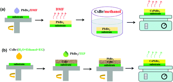 | ||
| Fig. 1 Schematic illustration of the fabrication process of Cs–Pb–Br films through different routes: (a) traditional route using toxic solvents and (b) anomalous route using green solvents. | ||
Characterization
The samples were separately characterized by X-ray diffraction (XRD, PANalytical X'Pert3 Powder), field-emission scanning electron microscopy (SEM, Nova NanoSEM 430), and UV-VIS spectrophotometry (UV-2550). The current density–voltage (J–V) curves were obtained under AM 1.5G simulated solar illumination, and recorded using a Keithley 2400 source meter. Incident photon-to-current conversion efficiency (IPCE) spectra were recorded using an integrated system from Enlitech (QE-R3011). Steady and time resolved photoluminescence (PL) spectra were obtained using a photoluminescence spectrometer instrument (Edinburgh Instruments, LP 980). Impedance spectroscopy (IS) spectra were recorded using an electrochemical workstation (CHI660D) under dark conditions.3. Results and discussion
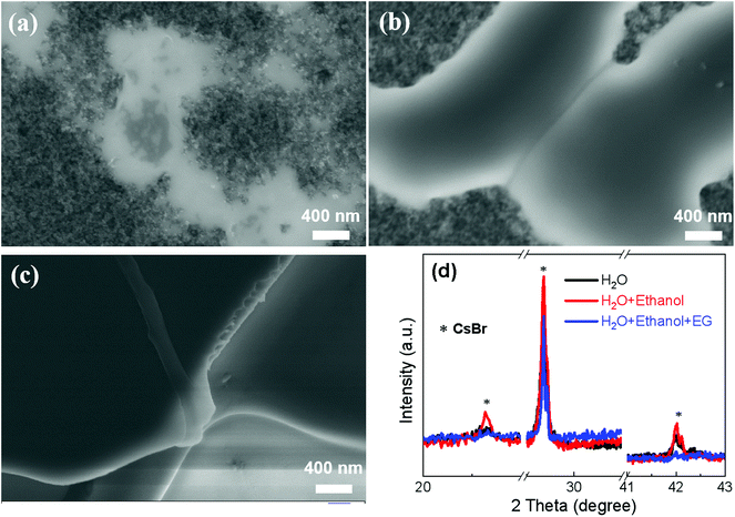
In light of the high solubility of CsBr (∼5.8 M) in water at room temperature,21 we firstly prepared CsBr films using CsBr/H2O (∼1.0 M) in the first step. Fig. 2a shows a SEM image of the CsBr film directly prepared from the CsBr/H2O solution, showing a discontinuous film composed of some isolated grains. The discontinuous CsBr film might be ascribed to the poor wettability, which is confirmed from a large contact angle (∼30°) of water on substrates (see Fig. S3a†). In order to improve the wettability of the solution, we employ a green mixed solvent system composed of H2O and ethanol (volume ratio of v/v = 1![[thin space (1/6-em)]](https://www.rsc.org/images/entities/char_2009.gif) :
:![[thin space (1/6-em)]](https://www.rsc.org/images/entities/char_2009.gif) 1) to dissolve the CsBr (∼1.0 M). The contact angle almost decreases to zero (see Fig. S3b†). As shown in Fig. 2b, the CsBr transforms from isolated grains to a ribbon-like network. However, there still are large areas of voids in the CsBr films.
1) to dissolve the CsBr (∼1.0 M). The contact angle almost decreases to zero (see Fig. S3b†). As shown in Fig. 2b, the CsBr transforms from isolated grains to a ribbon-like network. However, there still are large areas of voids in the CsBr films.
In order to obtain continuous CsBr films, we introduce 10% EG into a mixture of H2O and ethanol (v/v = 1![[thin space (1/6-em)]](https://www.rsc.org/images/entities/char_2009.gif) :
:![[thin space (1/6-em)]](https://www.rsc.org/images/entities/char_2009.gif) 1) to prepare a CsBr solution. Surprisingly, it forms a desired continuous and smooth CsBr film with a full coverage surface (see Fig. 2c). The low magnification SEM images of CsBr films are also given in Fig. S4,† reconfirming the characteristic morphology on a large scale as discussed above. Fig. 2d shows the XRD curves of the CsBr films fabricated from different solutions. There are characteristic diffraction peaks of CsBr centered at 20.6°, 29.3° and 42.0° in all of the XRD curves (see Fig. S5†), which are consistent with a previous report.22 This implies that the films prepared from the CsBr solutions are composed of mainly CsBr crystals.
1) to prepare a CsBr solution. Surprisingly, it forms a desired continuous and smooth CsBr film with a full coverage surface (see Fig. 2c). The low magnification SEM images of CsBr films are also given in Fig. S4,† reconfirming the characteristic morphology on a large scale as discussed above. Fig. 2d shows the XRD curves of the CsBr films fabricated from different solutions. There are characteristic diffraction peaks of CsBr centered at 20.6°, 29.3° and 42.0° in all of the XRD curves (see Fig. S5†), which are consistent with a previous report.22 This implies that the films prepared from the CsBr solutions are composed of mainly CsBr crystals.
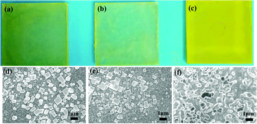
Fig. 3a–c show a photograph of the Cs–Pb–Br films fabricated from different solvent systems. The Cs–Pb–Br films fabricated from H2O and a mixture of (H2O + ethanol) mainly are light white decorated with some yellow dots (see Fig. 3a and b). However, the Cs–Pb–Br film fabricated from the mixture solvents of (H2O + ethanol + EG) shows a uniform yellow morphology (see Fig. 3c). The corresponding SEM images of the three Cs–Pb–Br films are shown in Fig. 3d–f. The Cs–Pb–Br films fabricated from H2O and ethanol solution without adding EG consist of many isolated grains (see Fig. 3d and e). However, the Cs–Pb–Br films fabricated from solvent systems of (H2O + ethanol + EG) show a continuous morphology with full coverage (see Fig. 3f). The XRD curves of the Cs–Pb–Br films also are given in Fig. S6.† They show that only the films fabricated from CsBr/(H2O + ethanol + EG) afford the desired pure CsPbBr3 for application in solar cells. These results demonstrate that it is important to prepare continuous CsBr films in the first step from a suitable solvent system, which directly affects the morphology and phase of the resultant Cs–Pb–Br films. Hereafter, we choose the mixed solvents of H2O + ethanol + EG to prepare CsBr and CsPbBr3 films so as to fabricate perovskite solar cells.
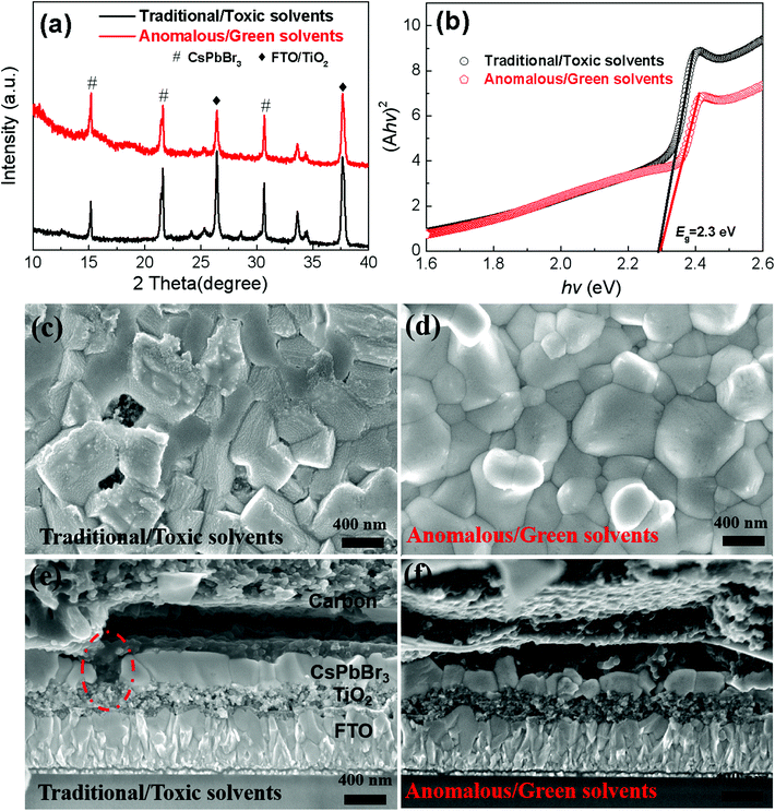
In order to compare the performance of the solar cells, the CsPbBr3 layers are separately prepared through the traditional sequential deposition route using the toxic DMF solvent (see Fig. 1a) and the anomalous sequential deposition route using green solvents (see Fig. 1b). Hereafter, we lable the samples according to their fabrication route (Traditional or Anomalous) and solvent (Toxic solvents or Green solvents) for the following discussion. For the Cs–Pb–Br films fabricated through the traditional sequential deposition route, they were prepared using the optimized dipping time (9 min) based on the best morphology (see Fig. S7†) and pure phase of CsPbBr3 (see Fig. S8†). Fig. 4a shows the XRD curves of the Cs–Pb–Br film fabricated through different deposition routes with the optimized fabrication conditions. There are evident characteristic diffraction peaks at 15.2°, 21.6° and 30.6° in the two XRD curves, corresponding to the (100), (110) and (200) planes of CsPbBr3.16Fig. 4b shows the relationship between (Ahv)2 and photoenergy (hv) of the CsPbBr3 perovskite films. The bandgap of the CsPbBr3 films is fitted to be ∼2.3 eV, which is consistent with the previous work.17Fig. 4c shows a high magnification SEM image of the CsPbBr3 films fabricated through the traditional sequential deposition route. There are some voids in the films, which might lead to direct contact between TiO2 and the carbon electrode. Fig. 4e shows such a short contact between the carbon electrode and the TiO2 layer. Fig. 4d shows a top-view SEM image of the CsPbBr3 film fabricated through the anomalous sequential deposition route. It shows a full coverage morphology, which is also further confirmed from the cross-sectional SEM image of a complete PSC (see Fig. 4f). The fully covered CsPbBr3 films in the solar cells can prevent the direct contact between carbon and TiO2, which is strongly desired for fabricating highly efficient PSCs. It is noted that the thickness of the CsPbBr3 films is about 260 nm. The thickness of the CsPbBr3 films is mainly limited by the highest solubility of PbBr2 in TEP (∼60 mg mL−1). It will produce an undesired phase, including Cs4PbBr6 and residual CsBr in the Cs–Pb–Br films if a higher concentration of CsBr solution (∼1.5 M) is used in the first step (see Fig. S9†).
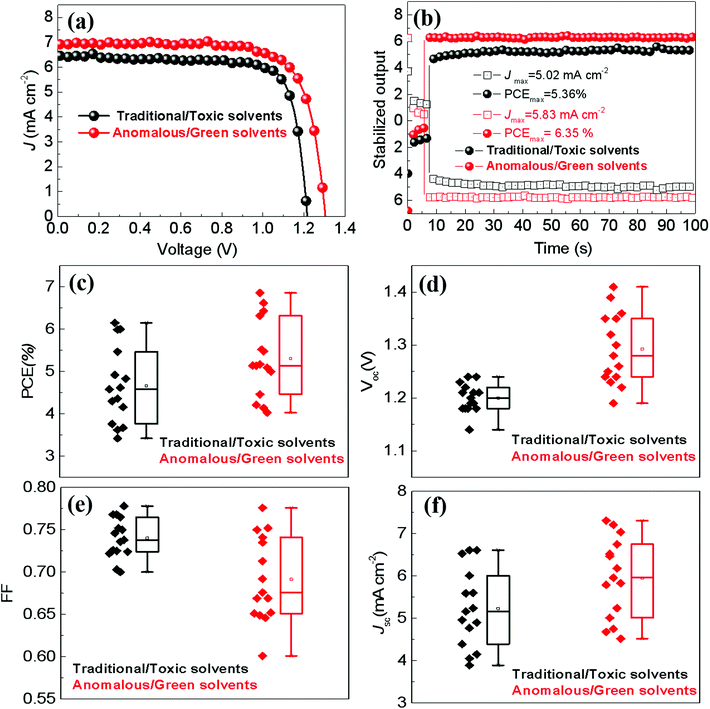
Fig. 5a shows the light J–V curves of the best PSCs with a typical device configuration of FTO/TiO2/CsPbBr3/carbon (see Fig. 4e and f), where the CsPbBr3 films are fabricated through two different deposition routes. The PSCs prepared through the anomalous sequential deposition route show a power conversion efficiency (PCE) of 6.86%, a short current density (Jsc) of 7.04 mA cm−2, an open-circuit voltage (Voc) of 1.30 V, and a fill factor (FF) of 0.750. The IPCE spectra of the solar cells are shown in Fig. S10.† It shows that they exhibit a quantum yield in the range from 300 nm to 539 nm, which is consistent with a bandgap of 2.3 eV (see Fig. 4b). The integrated Jsc from the IPCE spectrum is 5.37 mA cm−2, which is lower than the value obtained from the reverse scan. This phenomenon is widely observed in the research of CsPbBr3 based solar cells from several independent groups.23–27 The discrepancy may be ascribed to the loss of ultraviolet spectra during IPCE characterization.25,27 However, the best PSC prepared through the traditional sequential deposition route exhibits an inferior PCE of 6.15%, a Jsc of 6.53 mA cm−2, a Voc of 1.21 V and a FF of 0.778. Fig. 5b shows the stabilized outputs of the best PSCs at the maximum power points. The best PSC fabricated through the anomalous sequential deposition route has a stabilized current density of 5.83 mA cm−2, delivering a stabilized PCE of 6.35%. However, the stabilized output current density and PCE are 5.02 mA cm−2 and 5.36%, respectively, for the best PSC fabricated through the traditional sequential deposition route. It is noted that both the stabilized outputs are slightly lower than the value obtained from reverse scans (see Fig. 5a). This phenomenon is widely reported in the research of PSCs with hysteresis behaviors28,29 (see Fig. S11†), which may come from the interface between FTO and the compact TiO2 layer.30 The detailed comparison of the photovoltaic parameters of the best PSCs between this work and previous reports with a typical device configuration of FTO/TiO2/CsPbBr3/carbon without any modification is listed in Table S1.† Meanwhile, the solvents used to prepare CsPbBr3 films in these works are also listed in Table S1.† It clearly shows that the performance of the PSCs in this work is comparable to those fabricated using a toxic solvent system used by independent research groups. This strongly demonstrates that the anomalous sequential deposition route in this work is an effective and environmentally friendly approach to prepare CsPbBr3-based solar cells without efficiency loss.
Fig. 5c–f show the statistical results of the photovoltaic parameters based on a series of PSCs fabricated through different deposition routes. The superior PCE of PSCs fabricated through the anomalous sequential deposition route is mainly attributed to the significantly enhanced Voc (see Fig. 5d). In order to explore the mechanisms of the Voc improvement of PSCs, PL spectra of CsPbBr3 films on glasses are recorded. As shown in Fig. 6a, both the CsPbBr3 films have an emission peak at ∼527 nm, corresponding to a bandgap of ∼2.35 eV, which is consistent with the results obtained from the UV-Vis spectra (see Fig. 4b). However, the CsPbBr3 films prepared through the anomalous route using green solvents exhibit higher PL intensity than that prepared through the traditional route using toxic solvents. The higher PL intensity indicates the low trap density of the CsPbBr3 films prepared through the anomalous route using green solvents.15Fig. 6b shows the time-resolved PL spectra of CsPbBr3 films prepared through different routes. All the curves can be well fitted by the exponential equation,  , where τ1 and τ2 are the fast and slow decay times, and A1 and A2 are the relative amplitudes, respectively.31 The average life time (τave) is calculated based on the equation, τave = (A1τ21 + A2τ22)/(A1τ1 + A2τ2).31 The CsPbBr3 films prepared through the anomalous route using green solvents exhibit an average lifetime of 3.36 ns, which is longer than the value (2.04 ns) obtained for the CsPbBr3 films prepared through the traditional route using toxic solvents (see Table S2†). The longer lifetime reconfirms the low trap density of the CsPbBr3 films prepared through the anomalous route using green solvents. Fig. 6c shows the impedance spectroscopy (IS) spectra of the best PSCs prepared through different routes. All PSCs exhibit an arc in the low frequency region, which reflects the recombination rate in PSCs. The larger the arc in the IS spectra, the lower the recombination rate in PSCs.32 As shown in Fig. 6c, the PSC prepared through the anomalous route using green solvents exhibits a larger arc than that prepared through the traditional route using toxic solvents, indicating a lower recombination rate in the solar cells. Therefore, the low recombination rate and fully covered CsPbBr3 films contribute to the enhancement of Voc in the PSCs prepared through the anomalous route using green solvents in comparison with the ones prepared through the traditional route using toxic solvents.
The stability of PSCs is a key factor for the industrialization of PSCs. We also characterize the stability of PSCs in air without any encapsulation. Fig. 7 shows the evolution of the normalized parameters of PSCs with the increase of the storage time in air (with a relative humidity of ∼40% and a temperature of ∼30 °C). This shows that the PCE still exhibits a comparable value to the initial value when the device was stored in air for 14 days, showing the excellent stability of CsPbBr3 based PSCs. The excellent stability is mainly attributed to the high stability of CsPbBr313,33and all inorganic functional layers in the solar cells.
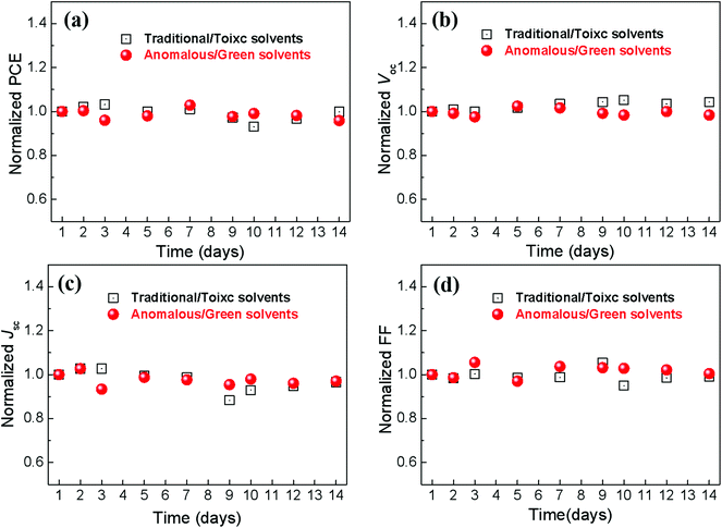 | ||
| Fig. 7 The evolution of normalized parameters of the PSCs under air conditions without encapsulation. (a) PCE; (b) Voc; (c) Jsc; (d) FF. | ||
4. Conclusions
Full coverage CsPbBr3 films are prepared through an anomalous sequential deposition route, in which green solvents are used to prepare CsBr and PbBr2 solutions. Different from those obtained by the traditional sequential deposition route, CsBr films are firstly deposited onto substrates, and then reacted with PbBr2 to form full coverage CsPbBr3 films through a dynamic spin-coating process. A power conversion efficiency of 6.86% is achieved for the solar cells with an unmodified configuration of FTO/TiO2/CsPbBr3/carbon, which is comparable to that of the solar cells prepared through the traditional sequential deposition route using toxic solvents. This work not only provides a new route to prepare CsPbBr3 films but also addresses the solvent toxicity for processing CsPbBr3 films. It is an environment-friendly route, which has great potential in fabricating CsPbBr3-based devices, such as resistive memory, light-emitting diodes, photodetectors, and so on.Conflicts of interest
There are no conflicts to declare.Acknowledgements
This work was financially supported by the Innovation Projects of Department of Education of Guangdong Province (2019KQNCX155), the Science Foundation for High-level Talents of Wuyi University (2019AL001), the National Natural Science Foundation of China (51972188), the Featured Innovation Projects of Colleges and Universities in Guangdong Province (2018KTSCX232), the Innovative Leading Talents of Jiangmen [Jaingren (2019) 7], the Science and Technology Projects of Jiangmen (No. (2017) 307, (2017) 149, (2018) 352), the Cooperative education platform of Guangdong Province (No. (2016) 31) and the Key Laboratory of Optoelectronic materials and Applications in Guangdong Higher Education (No: 2017KSYS011).References
- A. Kojima, K. Teshima, Y. Shirai and T. Miyasaka, J. Am. Chem. Soc., 2009, 131, 6050–6051 CrossRef CAS.
- National Renewable Energy Laboratory Best Research-cell efficiencies. http://www.nrel.gov/pv/assets/images/efficiency-chart.png.
- D. H. Kim, J. B. Whitaker, Z. Li, M. F. A. M. van Hest and K. Zhu, Joule, 2018, 2, 1437–1451 CrossRef CAS.
- N. J. Jeon, J. H. Noh, Y. C. Kim, W. S. Yang, S. Ryu and S. Seok, Nat. Mater., 2014, 13, 897–903 CrossRef CAS.
- M. Xiao, F. Huang, W. Huang, Y. Dkhissi, Y. Zhu, J. Etheridge, A. Gray-Weale, U. Bach, Y. B. Cheng and L. Spiccia, Angew. Chem., Int. Ed., 2014, 53, 9898–9903 CrossRef CAS.
- P. Zhao, B. J. Kim, X. Ren, D. G. Lee, G. J. Bang, J. B. Jeon, W. B. Kim and H. S. Jung, Adv. Mater., 2018, 30, 1802763 CrossRef.
- M. Zhang, Z. Wang, B. Zhou, X. Jia, Q. Ma, N. Yuan, X. Zheng, J. Ding and W. H. Zhang, Sol. RRL, 2018, 2, 1700213 CrossRef.
- M. Yavari, M. Mazloum-Ardakani, S. Gholipour, M. M. Tavakoli, S. Turren-Cruz, N. Taghavinia, M. Grätzel, A. Hagfeldt and M. Saliba, Adv. Energy Mater., 2018, 8, 1800177 CrossRef.
- D. Xin, Z. Wang, M. Zhang, X. Zheng, Y. Qin, J. Zhu and W. H. Zhang, ACS Sustainable Chem. Eng., 2019, 7, 4343–4350 CrossRef CAS.
- T. Bu, L. Wu, X. Liu, X. Yang, P. Zhou, X. Yu, T. Qin, J. Shi, S. Wang, S. Li, Z. Ku, Y. Peng, F. Huang, Q. Meng, Y. B. Cheng and J. Zhong, Adv. Energy Mater., 2017, 7, 1700576 CrossRef.
- M. Wang, Q. Fu, L. Yan, P. Guo, L. Zhou, G. Wang, Z. Zheng and W. Luo, ACS Appl. Mater. Interfaces, 2019, 11, 3909–3916 CrossRef CAS.
- Y. Yun, F. Wang, H. Huang, Y. Fang, S. Liu, W. Huang, Z. Cheng, Y. Liu, Y. Cao, M. Gao, L. Zhu, L. Wang, T. Qin and W. Huang, Adv. Mater., 2020, 30, 1907123 CrossRef.
- M. Kulbak, D. Cahen and G. Hodes, J. Phys. Chem. Lett., 2015, 6, 2452–2456 CrossRef CAS.
- X. Chang, W. Li, L. Zhu, H. Liu, H. Geng, S. Xiang, J. Liu and H. Chen, ACS Appl. Mater. Interfaces, 2016, 8, 33649–33655 CrossRef CAS.
- P. Teng, X. Han, J. Li, Y. Xu, L. Kang, Y. Wang, Y. Yang and T. Yu, ACS Appl. Mater. Interfaces, 2018, 10, 9541–9546 CrossRef CAS.
- X. Liu, X. Tan, Z. Liu, H. Ye, B. Sun, T. Shi, Z. Tang and G. Liao, Nano Energy, 2019, 56, 184–195 CrossRef CAS.
- J. Duan, Y. Zhao, B. He and Q. Tang, Angew. Chem., Int. Ed., 2018, 57, 3787–3791 CrossRef CAS.
- X. Cao, G. Zhang, L. Jiang, Y. Cai, Y. Gao, W. Yang, X. He, Q. Zeng, G. Xing, Y. Jia and J. Wei, ACS Appl. Mater. Interfaces, 2020, 12, 5925–5931 CrossRef CAS.
- M. Li and T. Zeng, Chem.-Biol. Interact., 2019, 298, 129–136 CrossRef CAS.
- R. Wrbitzky, Int. Arch. Occup. Environ. Health, 1999, 72, 19–25 CrossRef CAS.
- L. Wu, H. Hu, Y. Xu, S. Jiang, M. Chen, Q. Zhong, D. Yang, Q. Liu, Y. Zhao, B. Sun, Q. Zhang and Y. Yin, Nano Lett., 2017, 17, 5799–5804 CrossRef CAS.
- V. M. Brendel, S. V. Garnov, T. F. Yagafarov, L. D. Iskhakova and R. P. Ermakov, Quantum Electron., 2014, 44, 841–844 CrossRef.
- D. Huang, P. Xie, Z. Pan, H. Rao and X. Zhong, J. Mater. Chem. A, 2019, 7, 22420–22428 RSC.
- G. Tong, T. Chen, H. Li, L. Qiu, Z. Liu, Y. Dang, W. Song, L. K. Ono, Y. Jiang and Y. Qi, Nano Energy, 2019, 65, 104015 CrossRef CAS.
- G. Tong, T. Chen, H. Li, W. Song, Y. Chang, J. Liu, L. Yu, J. Xu, Y. Qi and Y. Jiang, Sol. RRL, 2019, 3, 1900030 CrossRef.
- J. Lei, F. Gao, H. Wang, J. Li, J. Jiang, X. Wu, R. Gao, Z. Yang and S. F. Liu, Sol. Energy Mater. Sol. Cells, 2018, 187, 1–8 CrossRef CAS.
- H. Li, G. Tong, T. Chen, H. Zhu, G. Li, Y. Chang, L. Wang and Y. Jiang, J. Mater. Chem. A, 2018, 6, 14255–14261 RSC.
- N. K. Noel, A. Abate, S. D. Stranks, E. S. Parrott, V. M. Burlakov, A. Goriely and H. J. Snaith, ACS Nano, 2014, 8, 9815–9821 CrossRef CAS.
- Y. Zhang, M. Liu, G. E. Eperon, T. C. Leijtens, D. McMeekin, M. Saliba, W. Zhang, M. Bastiani, A. Petrozza, L. M. Herz, M. B. Johnston, H. Lin and H. J. Snaith, Mater. Horiz., 2015, 2, 315–322 RSC.
- A. K. Jena, H. W. Chen, A. Kogo, Y. Sanehira, M. Ikegami and T. Miyasaka, ACS Appl. Mater. Interfaces, 2015, 7, 9817–9823 CrossRef CAS.
- J. Chen, X. Zhao, S. G. Kim and N. G. Park, Adv. Mater., 2019, 31, 1902902 CrossRef.
- X. Dong, D. Chen, J. Zhou, Y. Z. Zheng and X. Tao, Nanoscale, 2018, 10, 7218–7227 RSC.
- M. Kulbak, S. Gupta, N. Kedem, I. Levine, T. Bendikov, G. Hodes and D. Cahen, J. Phys. Chem. Lett., 2016, 7, 167–172 CrossRef CAS.
Footnote |
| † Electronic supplementary information (ESI) available. See DOI: 10.1039/d0gc02892d |
| This journal is © The Royal Society of Chemistry 2021 |

