Advanced fuels from ethanol – a superstructure optimization approach†
Juan Manuel
Restrepo-Flórez
 a and
Christos T.
Maravelias
 *abc
*abc
aDepartment of Chemical and Biological Engineering, University of Wisconsin–Madison, 1415 Engineering Drive, Madison, WI 53706, USA
bDepartment of Chemical and Biological Engineering, Princeton University, 50-70 Olden St, Princeton, NJ 08540, USA
cAndlinger Center For Energy and the Environment, 86 Olden St, Princeton, NJ 08540, USA. E-mail: maravelias@princeton.edu
First published on 16th December 2020
Abstract
We develop a superstructure framework for the design of biorefineries for ethanol upgrading into advanced biofuels to replace gasoline, jet fuel or diesel. The framework integrates catalysis, process synthesis, and fuel property modelling towards the design of biorefineries producing fuels with specified properties. The proposed framework is applied to identify strategies for the upgrading of ethanol into one or more fuels with specific properties. We discuss the trade-off between profit and biorefinery complexity, as well as the relation among fuel property constraints, the optimal upgrading strategy selected, and process economics. Finally, we show how to find the optimal biorefinery associated with a particular chemistry or catalyst. The results presented constitute the first systematic study of ethanol upgrading considering, simultaneously, fuel and process design.
Broader contextEthanol is the most common biofuel, typically blended with gasoline at a maximum 10% level. Considering current trends in fuel consumption and the expected increase in ethanol production capacity, it is projected that a surplus of ethanol will be available in the market. Consequently, numerous ethanol upgrading strategies have been studied. These strategies involve the use of several chemistries (e.g. dehydration, condensation, and Guerbet coupling) for the conversion of ethanol into different fungible molecules (e.g. olefins, alcohols, and ethers). However, the systematic analysis of these strategies is challenging due to the large number of available chemistries, catalysts, and processes. At the same time, there is a wide range of advanced biofuel targets, potentially outperforming their fossil-fuel-derived counterparts, whose properties could be tailored depending on the selected upgrading strategy. Accordingly, the goal of this work is to develop a framework for the design of novel and efficient ethanol upgrading strategies towards fuels with desirable properties. The interdisciplinary nature of the problem requires the integration of catalysis, process systems engineering, and fuel property modelling. We apply the proposed framework to design ethanol upgrading biorefineries that produce advanced biofuels designed to replace gasoline, jet fuel, or diesel. |
Introduction
Concerns about global warming and energy independence have driven both governments and the private sector to invest in biofuel production research. The development of the ethanol industry is a notable example. Only in the U.S., ethanol annual production capacity has increased from 2 to 16 billion gallons in the last twenty years.1 While the adoption of a biofuel is a significant development, ethanol has two important limitations. First, to prevent corrosion, regulations in most countries limit the amount of ethanol that can be blended with fuels to 10%.2,3 Second, the demand for gasoline is decreasing4,5 while the demand for middle distillates (diesel and jet fuels) is increasing,6 but ethanol is a poor replacement for middle distillates.5 With the ethanol demand for gasoline blending satisfied,2 the increasing production capacity is likely to lead to a surplus of ethanol.1,7,8 Accordingly, we have seen a renewed interest in finding strategies to upgrade ethanol into more fungible molecules.5,9,10 Among these strategies, those leading to products that can be blended above 10% with fossil fuels are particularly important, especially if they can replace middle distillates.In the last 30 years, the upgrading of ethanol toward fungible molecules has significantly advanced. The corpus of this literature covers a diverse set of chemistries (e.g. Guerbet coupling, dehydration, and condensation) and catalysts, establishing ethanol as a platform chemical.5,9–19 Initial attempts to find ethanol upgrading strategies were oriented toward processes yielding final products similar to the ones derived from fossil fuels.5,10,18,20,21 However, trying to develop biofuels with the same composition and properties as the ones derived from oil may be short-sighted. The diversity of ethanol chemistries can be used to design tailored fuels whose performance is as good as or even better than that of fossil fuels in an economically viable manner. However, there are important challenges in achieving this vision. First, the design space of the problem at hand is very large. Second it is necessary to consider the interactions among three areas: catalysis, process synthesis, and fuel property modeling.
While ethanol chemistries have been extensively reviewed,5,10 a comprehensive and systematic analysis of ethanol upgrading strategies has not been attempted. Towards this goal, an optimization-based process synthesis and analysis framework can be beneficial. Such a framework allows the exploration of a large design space, enables the identification of critical trade-offs, and leads to preliminary process designs that can be further explored using rigorous simulation tools. Although the application of optimization-based process synthesis is not yet the standard in industry, it has been successfully applied in academia to address both general synthesis problems (e.g. design of heat exchanger networks,22,23 distillation sequences,24,25 and integrated process flowsheets26–29), as well as specific systems (e.g. selection of biopolymer synthesis straegies,30 synthesis of biorefineries,2,31–34 and design of shale gas plants35). Of particular importance here are approaches dealing with the synthesis of integrated biorefineries. That is, biorefineries in which multiple technologies are employed.36–40 Works in this field include efforts dealing exclusively with the process synthesis problem, without considering product properties,31,36,37,41–48 and to a lesser extent with the integrated process and product design problem.49–54 The product design component has been viewed from two different perspectives. First, there are studies in which product design is understood as molecular design, that is, the product is a single chemical species with specified properties. This kind of formulation heavily relies on group contribution methods, and Quantitative Structure–Activity Relationships (QSAR).50,53–57 Alternatively, product design is formulated as a blend design, that is, the goal is to choose an optimal set of molecules, from an available candidate pool, such that the resulting blend has tailored properties, calculated using blending rules.39,49,51,58
The integration of catalysis, process synthesis, and fuel property modeling, towards the formulation of a mathematical programming model can be achieved at two different levels: first, early-stage evaluation of candidate pathways; and second, evaluation of candidate flowsheets for which process information is available. In the early-stage evaluation, process information is limited. The goal is to find the optimal strategy, without performing detailed process simulations, using reasonable estimates of the total production costs, and the stoichiometry of a reaction network of interest.49,51,52,54 Toward this direction, significant work has been carried out at the Fuel Design Center at RWTH Aachen University, where Reaction Network Flux Analysis (RNFA)49,51,54,59 and Process Network Flux Analysis (PNFA)51,60 were developed as support tools for the design of tailor-made biofuels. Along the same lines, Daoutidis and coworkers52,61,62 studied the selection of an optimal pathway to obtain a product with specified properties. Other works of interest include those by Broadbelt and Shanks focused on the identification of bioprivileged molecules that can be easily transformed into other valuable chemicals.63–65 A different problem arises when there exists detailed information (i.e. process flow diagrams and economic parameters) for several processes that can be used to produce a set of biofuels, either in a standalone manner or integrated into a more complex flowsheet. An interesting question concerns the identification of the network of processes that maximizes the profit while producing fuels with desired properties. In general, strategies to address this question have relied on superstructure-based optimization.31,36,37,39,45,46,48,66 Notable examples include the Chemical Species/Conversion Operator (CSCO)36 approach, the Biomass Utilization Superstructure (BUS),31,45 the biomass bipartite graph representation (BBR),43 the integer-cuts constraint method for biorefinery design,46,66 and the Processing Step-Interval Network (PSIN) representation.48,67 However, most of these approaches do not consider the modeling of fuel properties, with the exception of the two-stage optimization approach by Ng and coworkers.39
In this paper, we present a superstructure-based optimization framework that can be used for simultaneous process and fuel design, and we apply it to study ethanol upgrading to various biofuels. The results constitute the first systematic analysis of ethanol upgrading strategies, providing insights into conversion pathways, as well as identifying the major cost drivers associated with these strategies. Furthermore, we explore the trade-off between biorefinery complexity and process economics; and discuss the relation between the fuel properties and the optimal biorefineries designed. Methodologically, we express the problem using a hierarchical superstructure which encompasses detailed decisions (e.g. catalyst selection based on chemistry selection), while enabling the coupling of the decisions made at the process level with the resulting product properties.
Framework
Superstructure architecture
The design of an ethanol upgrading biorefinery can be described in terms of three levels of decisions:(1) Selection of the species undergoing a chemical reaction; ethanol as the initial substrate is in the list of such species, but the selected strategy may involve subsequent transformations of other species (e.g., ethylene, butanol) produced from the initial ethanol transformation.
(2) Selection of the specific chemistries used for the transformation of the species selected at the first level; for example, if ethanol and ethylene were selected, then the chosen chemistries may be alcohol dehydration and oligomerization, respectively.
(3) Selection of the specific processes used to realize the chemistries chosen in the second level; these processes are characterized by the catalyst, the separation train used to obtain the products of interest, and the specific process conditions used.
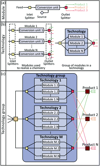
In this work, we have used two abstractions to systematically account for these decisions. First, we represent upgrading strategies as a sequence of conversion modules consisting of a catalytic conversion unit and its associated separation operations. Second, we introduce a hierarchical architecture to consider the three relevant decision levels simultaneously (Fig. 1).
The superstructure has three levels: Module (Fig. 1(a)), Technology (Fig. 1(b)), and Technology group (Fig. 1(c)). The module, which is the elemental building block of this approach, can be understood as a conversion process designed to transform one or more species into a set of products. The operation of a module is described using four elements: (1) an inlet mixer (light yellow square in the Fig. 1(a)) that combines inlet streams containing chemical species consumed in the module; (2) a conversion unit (light blue rectangle in Fig. 1(a)), characterized by a set of yield coefficients determining the amount of each species produced or consumed per mol of substrate in every reaction occurring in the module; (3) an outlet splitter (red square in Fig. 1(a)), described by a set of separation factors establishing the fraction of each chemical species directed toward each of the module's products; and (4) an optional source element (blue diamond in Fig. 1(a)), accounting for the supply of carrier gases or reactants not present in the feed stream. Each module has base capital and operating costs defined with respect to a reference incoming mass flow rate. Note that all the information associated with the performance of separation units and reactors is lumped in the yield coefficients and separation factors, and the economics of the process in the capital and operating cost parameters.
Different modules can be synthesized for the realization of the same chemistry (e.g., ethanol dehydration can be accomplished using a process employing a SynDol® catalyst, or a process employing a zeolite catalyst). All the modules designed for the realization of the same chemistry are grouped in the second level of the superstructure termed as a technology (Fig. 1(b)). Modules in a technology differ from each other either because they were designed using different catalysts or because they employ a different separation train. Only one module per technology can be selected. Thus, it is possible to lump together all the inlet mixers and outlet splitters associated with all the modules in a technology (Fig. 1(b)), knowing that the only active streams (i.e. those with flow greater than zero) are those connected to the selected module. Finally, at the third level, all the technologies consuming the same substrate are grouped into a technology group (Fig. 1(c)); for example, Guerbet coupling, condensation, and dehydration of ethanol belong to the same technology group because they process the same substrate. Since two technologies in the same technology group can be selected simultaneously, we do not constrain the system to prevent this kind of decision. In addition to the elements already described, a technology group contains an inlet splitter (dark yellow square in Fig. 1(c)) and a set of outlet splitters (burgundy squares in Fig. 1(c)). The inlet splitter distributes the incoming substrate stream toward the selected technologies. The output splitters distribute the obtained products toward the inlet splitters of other technology groups for further processing or toward the final products.
Optimization model
The resulting optimization model, which couples process synthesis decisions and fuel properties, is a mixed integer non-linear program (MINLP) model (see SI1, ESI† for the details) that can be used to find the optimal process producing fuels with tailored properties [eqn (1)]. While, in general, various objective functions can be used (e.g., economic, environmental), in this paper we use profit maximization defined as the difference between revenues and costs. Two sources of revenue were considered: fuel and electricity sales, with the fuels selling price set at 2$US per kg based on a recent technoeconomic analysis (TEA)68 and the electricity sold at 1.5 × 10⁻⁸ $US per J based on NREL report.8 Costs have three components: annualized capital investment, operating costs, and feed stream costs (see ESI† S7 for details on feedstock cost). All costs and prices are in 2007 dollars to be consistent with the reference year of the most recent NREL work on lignocellulosic ethanol production.8 | (1) |
The model is expressed using four types of sets: superstructure elements i ∈ I (subsets include: modules IMD, technologies ITCH, and technology groups ITG); chemical reactions r ∈ R; chemical components k ∈ K; and process streams j ∈ J (subsets include: fuel streams JP, and electricity streams JE). The process synthesis component of the model [eqn (S7)–(S34), ESI†] consists of mass balances written around the different elements of the superstructure, logical relations based on superstructure connectivity, capital costs scaling functions, and operating cost definitions. We introduce three binary variables accounting for the discrete decisions made at the different levels of the superstructure: module (YMi, i ∈ IMD), technology (YTi, i ∈ ITCH), and technology group (YTGi, i ∈ ITG). Each of these binaries is equal to one if the respective module, technology, or technology group is selected. Additionally, we have one binary variable for each fuel product (YFj, j ∈ JP), with these binaries being equal to one if the corresponding fuel is produced. All the aforementioned binaries are used to inactivate process streams, introduce integer cuts to find alternative solutions, and define logical constraints based on the superstructure architecture (e.g. if a technology is not selected then the modules associated with that technology cannot be selected). The property model consists of two parts [eqn (S35)–(S51), ESI†]: blending rules for the calculation of target properties as a function of the fuel composition; and composition constraints limiting the amount of specific chemical species such that fuel standards are met (e.g., upper bounds on aromatic content). The process synthesis and fuel property models are coupled because the fuel composition is a function of the selected technology groups, technologies, and modules.
Ethanol upgrading
We employ the proposed framework to study ethanol upgrading. The available chemistries, catalysts, and processes are integrated to generate a superstructure (see Fig. 2) with 14 technology groups and 25 technologies, incorporating process information for 87 different modules (See SI-2, ESI†). We consider the possibility of using, exclusively or simultaneously, three different ethanol substrates with different water content: 50%, 7%, and 0% [kg kg−1]. These concentrations were selected considering possible simplifications of the ethanol purification process. Specifically, a 50% blend can be obtained using only a beer distillation column; a 7% blend is close to the water ethanol azeotrope and can be obtained using a beer column followed by a rectification column; and a near 100% feedstock corresponds to the typical product of a bioethanol production plant in which both beer and rectification columns are used followed by a molecular sieving unit. Products include three fuel output streams: gasoline, jet fuel, and diesel; an electricity generation stream; and a waste stream. Although only energy products are considered in this work, the proposed framework can be readily extended to consider the co-production of other valuable chemicals.69,70 All fuel streams are constrained such that the resulting products display a set of properties consistent with those of typically used fuels.71–73 The considered properties as well as the enforced constraints are summarized in Table 1. Blending rules required for the estimation of these properties are described in the ESI† (SI-1).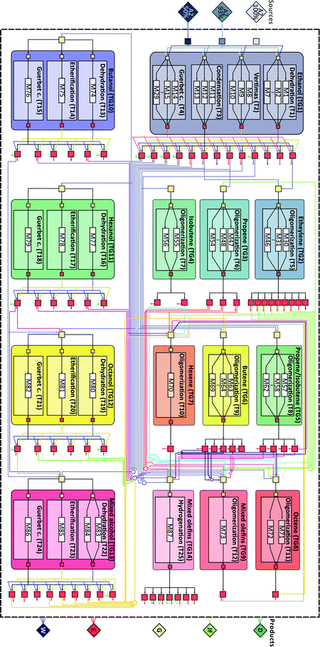 | ||
| Fig. 2 Ethanol upgrading superstructure illustrating the different technology groups (TG), technologies (T) and modules (M) used. Sources and final products are illustrated as diamonds to the left and right of the figure. Connections between technology groups are illustrated in accordance with the connectivity matrix in SI-3 (ESI†). | ||
| Type | Gasoline | Jet fuel | Diesel | |
|---|---|---|---|---|
| RON: research octane number. CN: cetane number. XT: mol fraction of fuel evaporated at T temperature. | ||||
| RON | Min | 91 | — | — |
| CN | Min | — | — | 40 |
| Density [kg m−3] | Max | 775 | 840 | 845 |
| Viscosity [mm2 s−1] | Min | — | — | 2.0 |
| Max | 2.0 | 8 | 4.5 | |
| X 30 [% mol%] | Max | 5 | — | — |
| X 215 [% mol] | Min | 98 | — | — |
| X 160 [% mol] | Max | — | 5 | — |
| X 300 [% mol] | Min | — | 98.5 | — |
| X 150 [% mol] | Max | — | — | 5 |
| X 360 [% mol] | Min | — | — | 95 |
| Olefins [% mol] | Max | 18 | 2 | 20 |
| Aromatics [% mol] | Max | 35 | 25 | 35 |
In the case of olefins, the chemistries of interest are limited to oligomerization,9,16–19 for which several processes, involving heterogeneous and homogeneous catalysts, have been developed. Although oligomerization reactions yield a mixture of branched and linear olefins, we have assumed, due to limited information for the catalysts of interest, that we obtain mainly linear olefins. In the case of higher alcohols there are three chemistries of interest: dehydration,95–100 Guerbet coupling,86 and etherification.86,98,101,102 The first two have already been discussed, but the difference here is that the products obtained when higher alcohols are used as substrates have a higher number of carbons. Etherification has been gaining attention because ethers of higher alcohols have very promising properties for tailor-made diesel fuel.86 From a fuel design perspective, the wide range of chemistries available leads to a large feasible space for the design of advanced fuels. A detailed list of all the species considered and their relevant properties is presented in the ESI† (see SI-4).
Catalysts. The design and characterization of catalysts available for the aforementioned chemistries has received considerable attention in the literature.5,10,12,15,16,19 A survey of available catalyst for the chemistries of interest is presented in the ESI† (see SI-5). Given the large number of available catalysts it is impractical to include all of them in the superstructure. Instead, we use a subset of carefully selected catalysts to represent a broad range of operating conditions and selectivities for each chemistry. The catalyst selection is based on a clustering procedure, in which we group together catalysts with similar selectivity under similar operating conditions. Next, from each cluster we select only one representative catalyst (see SI-2 and SI-5, ESI†). This procedure reduces the size of the problem while still maintaining a diverse set of alternatives. For the clustering we consider five criteria with a strong bearing on process design: operating temperature, operating pressure, single pass conversion, selectivity, and catalysis phase (i.e. homogeneous or heterogeneous). We note that each catalyst incorporated in the superstructure can be used in one or more modules (see SI-2 for the list of catalyst used in each module, and SI-6 for process details, ESI†), each of which has an associated set of reactions (see Tables S2-1, ESI†). We note that while most of the chemistries considered have been used in the petrochemical or the bio-renewables industries,3,5,13,16,83 many of the catalysts included in the framework have been tested only at a laboratory scale. However, the corresponding data are included in order to have a broader design space.
Results
Optimal ethanol upgrading biorefineries
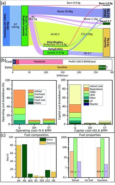
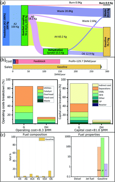
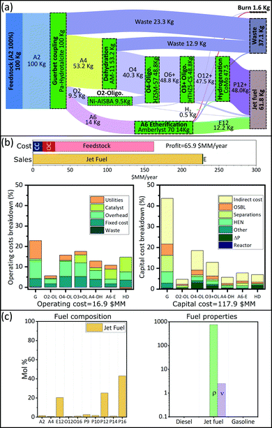
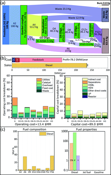
We are interested in finding optimal upgrading biorefineries for the transformation of ethanol into fuels with tailored properties. This question can be posed either generally, such that a multiproduct biorefinery is admissible; or in a more restricted way such that a single product biorefinery is pursued. In this last case, constraints on the admissible products are introduced using the binaries associated with each fuel (YFj ∈ j ∈ JP). We study four cases: a multiproduct biorefinery (Fig. 3), and three biorefineries in which a single fuel product with properties similar to those of gasoline (Fig. 4), jet fuel (Fig. 5), or diesel (Fig. 6) is obtained. Panel A in Fig. 3 through Fig. 6 shows a Sankey diagram illustrating mass flow across the biorefineries. In this diagram technologies that are part of the biorefinery appear as green blocks and the catalysts selected are indicated in the text; the flow of different streams is illustrated using areas of different color. The products (colored boxes on the right of the diagram) always include a waste sink, and an electricity generation sink (labeled as burn); fuel products on the other hand are added as needed based on the optimal biorefineries obtained. The results presented are normalized to 100 kg of feed allowing an easy interpretation of the results. Panel B of Fig. 3–6 presents the costs of the different biorefineries for a plant able to process ∼500 Ton-EtOH per day. Specifically, it shows a bar plot with the major costs (annualized capital (CC), operating cost excluding feedstock (OC), and feedstock) and revenues (from fuel and electricity sales); we also show two bar plots detailing the capital and operating costs breakdown. Finally, panel C shows the fuel composition, and properties of each product. We note that our results have been obtained assuming constant fuel prices, which implies that market variations may lead to decreased economic benefit. In principle, the proposed approach can be extended to a stochastic programming setting, where first stage decisions yield the biorefinery design, and second stage decisions yield operational strategies in different scenarios. However, the resulting formulations would be computationally expensive and are beyond the scope of this paper. Nevertheless, we note that the proposed model can still be used to find strategies that allow mitigation of the impact of price variability in the case of multiproduct biorefineries. Specifically, flows can be reconfigured among the selected blocks to optimize an updated objective function. The interested reader can find the details of this approach in SI 10 (ESI†).Discussion
The results obtained stress the significance of the framework adopted, not only we were able to identify an optimal biorefinery in economic terms, but also we tailored the process such that specific products with predefined properties were obtained. The fuel mixtures produced by the optimal biorefineries cannot be designed by intuition nor by applying heuristics. Only the use of process and systems engineering simultaneously considering process and fuel property constraints has enabled the design of biorefineries for the production of advanced fuels.Some insights can be obtained by analyzing the cost distribution of the processes studied. In all biorefineries the dominant cost driver is feedstock (bar plot in Fig. 3(b)–6(b)). Capital and operating costs (other than feedstock) account together for less than 20% of the annualized production cost. Specifically, the total capital investment is on the order of $100 million (annualized to $10 million per year for a 30 years project) in all cases; while the operating costs are between $10–$20 million per year. In contrast, the feedstock cost is close to ∼$130 million per year. This implies that biorefineries in which a higher yield is obtained are favored if the goal is to maximize the profit. Consequently, in all the optimal biorefineries Guerbet chemistry is selected. This chemistry is the one with the higher mass yield among the options for ethanol upgrading (Technology group 1). The reason for this higher yield is that Guerbet chemistry leads only to a partial dehydration. Conversely, other chemistries available for the initial ethanol transformation, like condensation and dehydration, fully dehydrate alcohols and therefore lead to a lower yield. In the case of condensation, the mass loss is even greater due to the loss of carbon in the form of carbon oxides.
The results suggest that there are two research directions that may lead to improvements in the economics of biofuel production. First, since the total product yield is so impactful on the economics, it is critical to develop highly selective catalysts, leading to less waste products, or by-products that cannot be incorporated in the final fuel. Second, in the case of Guerbet chemistry, the catalysts developed so far require the use of anhydrous ethanol. Thus, potential savings may be obtained if water tolerant catalyst are developed. Ethanol with a higher content of water is cheaper, especially when the concentration is below the azeotrope. Some advances have been reported in this direction.87 Also, improved efficiency in water–ethanol separation could have a positive effect. Although capital and operating costs (excluding feedstock) are not as impactful as the feedstock cost, improvements on these variables may lead to better economics. Finally, we see that the Guerbet coupling module, the largest one, dominates capital (43–91%) and operating (23–78%) costs (Fig. 3(b)–6(b)). Suggesting that the development of compact and efficient Guerbet coupling modules can lead to economic improvements.
Process complexity vs. efficiency
An important point regarding the biorefineries obtained for middle distillates (Fig. 5 and 6) is that their complexity, measured by the number of modules, is high (7 modules each), which may hinder its practical application. Thus, it is of interest to understand the effect of constraining the maximum number of modules. This consideration can be easily studied by introducing an additional constraint into the proposed optimization model. Specifically, if one is interested in obtaining biorefineries with a maximum number of modules it is sufficient to specify that , where “a” is an integer number. For the case of a diesel biorefinery, the results obtained when a reduced number of modules is used are presented in Fig. 7 and 8. Constraining the maximum number of modules leads to simpler biorefineries (Fig. 7) at the expense of reducing the profit. The Pareto front showing the trade-off between profit and complexity (number of modules) is shown in Fig. 8(a). Note, for example, that the profit obtained when 7 modules are used is ∼$78 million per year, whereas when three modules are used this value decreases more than 50% to ∼$30 million per year. This reduction is explained by the reduction in the fuel product yield. For the biorefinery in Fig. 6(a) (7 modules) the yield is ∼63%, whereas for the biorefinery in Fig. 7(b) (4 modules) the yield is ∼51%. Changes in the biorefinery configuration caused by constraining the maximum number of modules lead to changes in the final product composition and its properties (Fig. 8(b) and (c)). The most evident change is the increase in alcohols as the maximum number of modules decreases, leading to products with lower cetane number, which is expected provided that alcohols have lower cetane numbers than olefins with the same number of carbons.
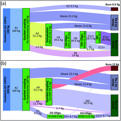 | ||
| Fig. 7 Sankey diagram based on mass flow for diesel production biorefineries when the number of modules is constrained to be less or equal than 5 (a) and less or equal than 4 (b). | ||
Understanding the trade-off between fuel properties and profit
The trade-off between fuel properties and profit can be studied by tightening the constraints on the fuel property model. We study the impact of tightening the cetane number requirements in a diesel biorefinery (Fig. 9 and Fig. SI.9, ESI†). As shown in Fig. 9(a), the profit starts to decrease as a function of cetane number once the product specification constraint becomes binding. For example, when the required cetane number increases from 61.4 (value at which the constraint becomes binding) to 80 the profit is reduced by approximately 8% ($6 million per year). Changes in costs and sales as a function of cetane number can be seen in Fig. 9(b), where we present a detailed breakdown of the cost components for the optimal biorefineries obtained for different cetane number specifications. Requiring a higher cetane number results in a smaller feasible space in terms of processes, that is, there are fewer configurations able to yield a product with the required properties. Details on the optimal processes obtained as a function of cetane number are presented in ESI† Fig. S9.1. Constraining the product has a direct impact on the selected processes. Changing the product requirements changes the technologies selected (Fig. S9.1, ESI†); e.g. increasing the cetane number above 61.4 leads to biorefineries in which an etherification module is used. The size of the etherification module increases concomitantly with the cetane number.In addition to modifying the technologies selected, specification-related constraints also affect the modules selected to realize each technology. As an illustration, when we enforce CN ≥ 40 or CN ≥ 70, the module selected for the ethylene oligomerization process uses Ni-AISBA as catalyst. In contrast, when we enforce CN ≥ 80 a Ni-LASA catalyst is selected. Both changes in the selected technologies and modules are aimed at modifying the final fuel product composition (Fig. 9(c)) such that the property constraints are satisfied. For example, we see in Fig. 9(c) that the amount of ethers, known for having a high cetane number, increases in the final product when higher cetane numbers are required. Likewise, the fraction of alcohols (A2, A4, and A6), all with cetane numbers lower than 20, decreases progressively as the specification on cetane number increases. This example clearly illustrates the interplay that exists between processes, fuel properties, and overall profit. Understanding and exploiting this relation is key for the design of biorefineries yielding tailored fuel products.
Identification of optimal strategy including a specific technology
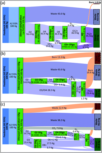
One relevant question that often arises, both at the experimental and process design levels, is how to identify the optimal biorefinery for the production of a candidate biofuel that includes a particular technology or catalyst. The framework that we have developed is suitable to address this kind of question. We investigate the design of biorefineries for the production of diesel fuel, employing the four technologies we consider for the initial ethanol transformation (i.e. dehydration, simultaneous dehydration and oligomerization, condensation, and Guerbet coupling). In addition to fixing the corresponding binary variables, we also enforce an additional condition preventing the system from selecting more than one technology in the first technology group , thereby enforcing the use of the technology of interest to process all incoming ethanol flow.
The optimal biorefineries employing the first three technologies (i.e. dehydration, simultaneous dehydration and oligomerization, and condensation) are presented in Fig. 10; results for the biorefinery that employs Guerbet coupling were already presented in Fig. 6. With respect to the results shown in Fig. 10, we observe that the strategies found involve the initial chemical transformation of ethanol followed by a set of oligomerization modules yielding a higher molecular weight product. Since the content of olefins is constrained in diesel fuels (see Table 1), the use of a hydrogenation module for the conversion of olefins into paraffins is required. In comparison with the diesel biorefinery using Guerbet coupling (Fig. 6), the results in Fig. 10 show an increase of almost 20% in the amount of waste water produced due to the higher degree of dehydration and the use of a substrate with higher water content (93% ethanol kg/per kg). Another difference is the increase in the size of the stream used for electricity generation, especially in the strategies in Fig. 10(b) and (c). This increase is caused by the generation of olefins that cannot be blended in the final product because their incorporation would cause an undesirable change in fuel properties.
Sensitivity analysis
Once an optimal biorefinery has been identified it can be further analyzed using sensitivity analysis tools to find the major cost drivers. In Fig. 11, we show the effect of perturbing relevant cost parameters on the annualized production cost of the four diesel biorefineries presented (Fig. 6 and 10). Since the major driver in all systems is the feedstock cost, and it is already known, we have excluded it from the analysis to visualize and identify other cost drivers. We consider three cost parameters for each of the technologies employed: utilities (±20%), catalyst and other feedstocks (−50%/+100%), and total investment (+100% and −20%). Perturbation values have been selected to reflect likely scenarios. In the case of utilities, changes of ±20% are considered due to better heat integration (−20%) or the need of incorporating additional separation units. Catalyst and other feedstocks costs on the other hand may change significantly because these are novel processes; for example, the cost of a catalyst can be reduced either by increasing its activity or by improving its manufacturing process. Finally, changes in the total investment reflect the risk associated with the installation of a first-of-a-kind system (+100%); and the less likely possibility of obtaining a better design (−20%) with similar functionality. In all cases three alternatives to achieve improvements in the process economics are identified. First, the cost of utilities is significant, especially for the ethanol processing technology, therefore optimizing heat integration is critical. Second, the consumption of catalyst and hydrogen in the hydrogenation module has a significant economic burden, therefore it is relevant to find alternatives to use by-product hydrogen as a feedstock. Finally, reducing the total investment cost associated with the ethanol processing technology (i.e. dehydration, dehydration and oligomerization, condensation or Guerbet coupling) plays an important role. The ethanol processing technology handles the largest amount of mass, consequently it is the most capital intensive.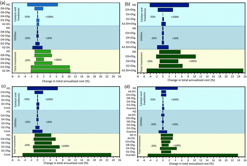 | ||
| Fig. 11 Tornado plot showing changes in the annualized production cost (excluding feedstock) when different cost parameters are perturbed: utilities (±20%), catalyst and other feedstocks (−50%, +100%), and total investment (−20%, +100%). (a) Diesel biorefinery based on ethanol Guerbet coupling (see Fig. 6). (b) Diesel biorefinery based on ethanol dehydration (see Fig. 10(a)). (c) Diesel biorefinery based on ethanol dehydration plus oligomerization (see Fig. 10(b)) (d) Diesel biorefinery based on ethanol condensation (see Fig. 10(c)). Blue bars are show operating costs while green bars show the capital investment. The y-axis shows the modules used, labelled using three parts: (i) an alphabetic component indicating the functional group of the substrate (A: alcohols, O: olefins); (ii) a numerical character indicating the number carbons of the substrate; and (iii) an alphabetic contraction indicating the chemistry used (DH: dehydration, Olig: oligomerization, HD: hydrogenation, Cond: condensation). | ||
Conclusions
In this paper, we have systematically studied the upgrading of ethanol toward advanced fuels with tailored properties. To integrate catalysis, process synthesis and fuel property modelling, we developed a superstructure-based optimization framework that simultaneously considers product (fuel) and process design. Using this framework, we explored the synthesis of biorefineries for the production of gasoline, diesel, and jet fuel. Additionally, we studied the trade-off between process complexity and profit, and the relation between fuel specifications and process synthesis. Finally, we showed how the framework developed can be used for the identification of the optimal biorefinery associated with a particular technology or catalyst. The results presented show the interdependencies between fuel specifications and the processes used to obtain those fuels. Changing fuel specifications lead to biorefineries with different technologies. Likewise, the chemical composition of the products changed as a function of the fuel property constraints. Understanding and exploiting these interdependencies is fundamental in the development of processes for fuels with superior properties. These results suggest that to unlock the full potential of a bio-based economy, systematic approaches, allowing us to design efficient processes for non-intuitive high-performance fuel blends, are necessary.Conflicts of interest
There are no conflicts to declare.Acknowledgements
This work was funded by the U.S. Department of Energy, grant number DE-EE0008480.References
- U.S. Energy Information Agency, Monthly Energy Review, November 2020, https://www.eia.gov/totalenergy/data/monthly/pdf/sec10_7.pdf Search PubMed.
- P. Fasahati and C. T. Maravelias, Joule, 2018, 2, 1915 CrossRef.
- L. Tao, J. N. Markham, Z. Haq and M. J. Biddy, Green Chem., 2017, 19, 1082 RSC.
- U.S. Energy Information Agency, Annual Energy Outlook 2019 with Projections to 2050, 2019.
- N. M. Eagan, M. D. Kumbhalkar, J. S. Buchanan, J. A. Dumesic and G. W. Huber, Nat. Rev. Chem., 2019, 3, 223 CrossRef CAS.
- International Energy Agency, The Future of Trucks: Implications for Energy and the Environment, 2017.
- M. Slupska and D. Bushong, Biofuels, Bioprod. Biorefin., 2019, 13, 857 CrossRef CAS.
- D. Humbird, R. Davis, L. Tao, C. Kinchin, D. Hsu, A. Aden, P. Schoen, J. Lukas, B. Olthof, M. Worley, D. Sexton and D. Dudgeon, Process Design and Economics for Biochemical Conversion of Lignocellulosic Biomass to Ethanol: Dilute-Acid Pretreatment and Enzymatic Hydrolysis of Corn Stover, Golden, Colorado, 2011 Search PubMed.
- V. Zacharopoulou and A. A. Lemonidou, Catalysts, 2018, 8, 2 CrossRef.
- J. Sun and Y. Wang, ACS Catal., 2014, 4, 1078 CrossRef CAS.
- H. Aitchison, R. L. Wingad and D. F. Wass, ACS Catal., 2016, 6, 7125 CrossRef CAS.
- J. T. Kozlowski and R. J. Davis, ACS Catal., 2013, 3, 1588 CrossRef CAS.
- D. Fan, D. J. Dai and H. S. Wu, Materials, 2013, 6, 101 CrossRef CAS.
- J. A. Posada, A. D. Patel, A. Roes, K. Blok, A. P. C. Faaij and M. K. Patel, Bioresour. Technol., 2013, 135, 490 CrossRef CAS.
- A. Finiels, F. Fajula and V. Hulea, Catal. Sci. Technol., 2014, 4, 2412 RSC.
- A. V. Lavrenov, T. R. Karpova, E. A. Buluchevskii and E. N. Bogdanets, Catal. Ind., 2016, 8, 316 CrossRef.
- V. Hulea, ACS Catal., 2018, 8, 3263 CrossRef CAS.
- C. P. Nicholas, Appl. Catal., A, 2017, 543, 82 CrossRef CAS.
- B. M. Antunes, A. E. Rodrigues, Z. Lin, I. Portugal and C. M. Silva, Fuel Process. Technol., 2015, 138, 86 CrossRef CAS.
- A. Galadima and O. Muraza, Ind. Eng. Chem. Res., 2015, 54, 7181 CrossRef CAS.
- J. Saavedra Lopez, R. A. Dagle, V. L. Dagle, C. Smith and K. O. Albrecht, Catal. Sci. Technol., 2019, 9, 1117 RSC.
- A. R. R. Ciric and C. A. Floudas, Comput. Chem. Eng., 1990, 14, 241 CrossRef CAS.
- C. A. Floudas, A. R. Ciric and I. E. Grossmann, AIChE J., 1986, 32, 276 CrossRef CAS.
- J. Ryu and C. T. Maravelias, AIChE J., 2020, 66, e16994 Search PubMed.
- H. Yeomans and I. E. Grossmann, Ind. Eng. Chem. Res., 2000, 39, 1637 CrossRef CAS.
- H. Yeomans and I. E. Grossmann, Comput. Chem. Eng., 1999, 23, 709 CrossRef CAS.
- L. Kong and C. T. Maravelias, Ind. Eng. Chem. Res., 2018, 57, 6330 CrossRef CAS.
- W. Wu, C. A. Henao and C. T. Maravelias, AIChE J., 2016, 62, 3199 CrossRef CAS.
- C. A. Henao and C. T. Maravelias, AIChE J., 2011, 57, 1296 CrossRef.
- E. A. del Rio-Chanona, D. Zhang and N. Shah, AIChE J., 2018, 64, 91 CrossRef CAS.
- J. Kim, S. M. Sen and C. T. Maravelias, Energy Environ. Sci., 2013, 6, 1093 RSC.
- P. E. Murillo-Alvarado, J. M. Ponce-Ortega, M. Serna-González, A. J. Castro-Montoya and M. M. El-Halwagi, Ind. Eng. Chem. Res., 2013, 52, 5177 CrossRef CAS.
- A. Kelloway and P. Daoutidis, Ind. Eng. Chem. Res., 2014, 53, 5261 CrossRef CAS.
- J. Gong and F. You, Ind. Eng. Chem. Res., 2014, 53, 1563 CrossRef CAS.
- J. Gong and F. You, AIChE J., 2018, 64, 123 CrossRef CAS.
- B. Bao, D. K. S. Ng, D. H. S. Tay, A. Jiménez-Gutiérrez and M. M. El-Halwagi, Comput. Chem. Eng., 2011, 35, 1374 CrossRef CAS.
- E. Zondervan, M. Nawaz, A. B. de Haan, J. M. Woodley and R. Gani, Comput. Chem. Eng., 2011, 35, 1752 CrossRef CAS.
- D. H. S. Tay, D. K. S. Ng, N. E. Sammons and M. R. Eden, Ind. Eng. Chem. Res., 2011, 50, 1652 CrossRef CAS.
- L. Y. Ng, V. Andiappan, N. G. Chemmangattuvalappil and D. K. S. Ng, Comput. Chem. Eng., 2015, 81, 288 CrossRef CAS.
- D. H. S. Tay, D. K. S. Ng, H. Kheireddine and M. M. El-Halwagi, Clean Technol. Environ. Policy, 2011, 13, 567 CrossRef CAS.
- D. Schack, L. Rihko-Struckmann and K. Sundmacher, Ind. Eng. Chem. Res., 2018, 57, 9889 CrossRef CAS.
- P. Cheali, J. A. Posada, K. V. Gernaey and G. Sin, Biomass Bioenergy, 2015, 75, 282 CrossRef CAS.
- A. C. Kokossis, M. Tsakalova and K. Pyrgakis, Comput. Chem. Eng., 2014, 81, 40 CrossRef.
- D. K. S. Ng, Chem. Eng. Trans., 2010, 21, 421 Search PubMed.
- R. T. L. Ng, S. Patchin, W. Wu, N. Seth and C. T. Maravelias, Biofuels, Bioprod. Biorefin., 2018, 12, 170 CrossRef CAS.
- A. D. Celebi, A. V. Ensinas, S. Sharma and F. Maréchal, Energy, 2017, 137, 908 CrossRef.
- V. Pham and M. M. El-Halwagi, AIChE J., 2012, 58, 1212 CrossRef CAS.
- M. O. Bertran, R. Frauzem, A. S. Sanchez-Arcilla, L. Zhang, J. M. Woodley and R. Gani, Comput. Chem. Eng., 2017, 106, 892 CrossRef CAS.
- M. Dahmen and W. Marquardt, Energy Fuels, 2017, 31, 4096 CrossRef CAS.
- F. T. Eljack, M. R. Eden, V. Kazantzi, X. Qin and M. M. El-Halwagi, AIChE J., 2007, 53, 1232 CrossRef CAS.
- A. König, L. Neidhardt, J. Viell, A. Mitsos and M. Dahmen, Comput. Chem. Eng., 2020, 134, 106712 CrossRef.
- W. A. Marvin, S. Rangarajan and P. Daoutidis, Energy Fuels, 2013, 27, 3585 CrossRef CAS.
- V. Kazantzi, X. Qin, M. El-Halwagi, F. Eljack and M. Eden, Ind. Eng. Chem. Res., 2007, 46, 3400 CrossRef CAS.
- M. Hechinger, A. Voll and W. Marquardt, Comput. Chem. Eng., 2010, 34, 1909 CrossRef CAS.
- M. Dahmen, M. Hechinger, J. Victoria Villeda and W. Marquardt, SAE Int. J. Fuels Lubr., 2012, 5, 990 CrossRef CAS.
- R. Gani, Comput. Chem. Eng., 2004, 28, 2441 CrossRef CAS.
- E. Conte and R. Gani, AIChE J., 2011, 57, 2431 CrossRef CAS.
- H. Hashim, M. Narayanasamy, N. A. Yunus, L. J. Shiun, Z. A. Muis and W. S. Ho, J. Clean. Prod., 2017, 146, 208 CrossRef CAS.
- A. Voll and W. Marquardt, AIChE J., 2012, 58, 1788 CrossRef CAS.
- K. Ulonska, M. Skiborowski, A. Mitsos and J. Viell, AIChE J., 2016, 62, 3096 CrossRef CAS.
- S. Rangarajan, A. Bhan and P. Daoutidis, Appl. Catal., B, 2014, 145, 149 CrossRef CAS.
- P. Daoutidis, W. A. Marvin, S. Rangarajan and A. I. Torres, AIChE J., 2012, 59, 215 Search PubMed.
- X. Zhou, Z. J. Brentzel, G. A. Kraus, P. L. Keeling, J. A. Dumesic, B. H. Shanks and L. J. Broadbelt, ACS Sustainable Chem. Eng., 2019, 7, 2414 CrossRef CAS.
- B. H. Shanks and P. L. Keeling, Green Chem., 2017, 19, 3177 RSC.
- M. B. Viswanathan, D. R. Raman, K. A. Rosentrater and B. H. Shanks, Processes, 2020, 8, 229 CrossRef.
- S. Maronese, A. V. Ensinas, A. Mian, A. Lazzaretto and F. Maréchal, Ind. Eng. Chem. Res., 2015, 54, 7038 CrossRef CAS.
- A. Quaglia, B. Sarup, G. Sin and R. Gani, Comput. Chem. Eng., 2012, 38, 213 CrossRef CAS.
- W.-C. Wang, L. Tao, J. Markham, Y. Zhang, E. Tan, L. Batan, M. Biddy, W.-C. Wang, L. Tao, Y. Zhang, E. Tan, E. Warner and M. Biddy, Review of Biojet Fuel Conversion Technologies-NREL/TP-5100-66291, 2016.
- K. Huang, P. Fasahati and C. T. Maravelias, iScience, 2020, 23, 100751 CrossRef CAS.
- R. T. L. Ng, P. Fasahati, K. Huang and C. T. Maravelias, Appl. Energy, 2019, 241, 491 CrossRef.
- J. Bacha, J. Freel, A. Gibbs, L. Gibbs, G. Hemighaus, K. Hoekman, J. Horn, M. Ingham, L. Jossens, D. Kohler, D. Lesnini, J. McGeehan, M. Nikanjam, E. Olsen, R. Organ, B. Scott, M. Sztenderowicz, A. Tiedemann, C. Walker, J. Lind, J. Jones, D. Scott and J. Mills, Diesel Fuels Technical Review, San Ramon, 2007, pp. 1–116 Search PubMed.
- ASTM D4814-14b, Standard Specification for Automotive Spark-Ignition Engine Fuel, 2014.
- ASTM D1655-19a, Standard Specification for Aviation Turbine Fuels, 2010.
- A. Mohsenzadeh, A. Zamani and M. J. Taherzadeh, ChemBioEng Rev., 2017, 4, 75 CrossRef.
- M. Zhang and Y. Yu, Ind. Eng. Chem. Res., 2013, 52, 9505 CrossRef CAS.
- F. Xue, C. Miao, Y. Yue, W. Hua and Z. Gao, Fuel Process. Technol., 2019, 186, 110 CrossRef CAS.
- F. Wang, W. Xia, X. Mu, K. Chen, H. Si and Z. Li, Appl. Surf. Sci., 2018, 439, 405 CrossRef CAS.
- F. Hayashi and M. Iwamoto, ACS Catal., 2013, 3, 14 CrossRef CAS.
- W. Xia, F. Wang, L. Wang, J. Wang and K. Chen, Catal. Lett., 2020, 150–158 CrossRef CAS.
- W. Xia, X. Mu, F. Wang, K. Chen, H. Si and Z. Li, React. Kinet., Mech. Catal., 2017, 122, 473 CrossRef CAS.
- M. Iwamoto, Catal. Today, 2015, 242, 243 CrossRef CAS.
- F. Liu, Y. Men, J. Wang, X. Huang, Y. Wang and W. An, ChemCatChem, 2017, 9, 1758 CrossRef CAS.
- J. R. Hannon, L. R. Lynd, O. Andrade, P. T. Benavides, G. T. Beckham, M. J. Biddy, N. Brown, M. F. Chagas, B. H. Davison, T. Foust, T. L. Junqueira, M. S. Laser, Z. Li, T. Richard, L. Tao, G. A. Tuskan, M. Wang, J. Woods and C. E. Wyman, Proc. Natl. Acad. Sci. U. S. A., 2020, 117, 12576–12583 CrossRef CAS.
- Z. Song, A. Takahashi, I. Nakamura and T. Fujitani, Appl. Catal., A, 2010, 384, 201 CrossRef CAS.
- W. Xia, K. Chen, A. Takahashi, X. Li, X. Mu, C. Han, L. Liu, I. Nakamura and T. Fujitani, Catal. Commun., 2016, 73, 27 CrossRef CAS.
- N. M. Eagan, B. J. Moore, D. J. McClelland, A. M. Wittrig, E. Canales, M. P. Lanci and G. W. Huber, Green Chem., 2019, 3300–3318 RSC.
- I. Nezam, L. Peereboom and D. J. Miller, J. Cleaner Prod., 2019, 209, 1365 CrossRef CAS.
- J. Pang, M. Zheng, L. He, L. Li, X. Pan, A. Wang, X. Wang and T. Zhang, J. Catal., 2016, 344, 184 CrossRef CAS.
- C. Zhang, K. Balliet and V. J. Johnston, US pat. 8962897B2, 2012.
- C. Zhang, K. Balliet and V. J. Johnston, US pat. 9024090B2, 2012.
- E. C. Tan, L. J. Snowden-Swan, M. T. Abhijit-Dutta, S. Jones, K. K. Ramasamy, M. Gray, R. Dagle, A. Padmaperuama, Ma. Gerber, A. H. Sahir, L. Tao and Y. Zhang, Biofuels, Bioprod. Biorefin., 2016, 11, 41 CrossRef.
- C. Zhang, US pat. 2014/0179958 A1, 2012.
- C. Zhang, M. Borlik and H. Weiner, WO2014100131A1, 2014.
- H. S. Ghaziaskar and C. C. Xu, RSC Adv., 2013, 3, 4271 RSC.
- P. Brandão, A. Philippou, J. Rocha and M. W. Anderson, Catal. Lett., 2002, 80, 99 CrossRef.
- Y. S. Hsu, Y. L. Wang and A. N. Ko, J. Chin. Chem. Soc., 2009, 56, 314 CrossRef CAS.
- N. P. Makgoba, T. M. Sakuneka, J. G. Koortzen, C. Van Schalkwyk, J. M. Botha and C. P. Nicolaides, Appl. Catal., A, 2006, 297, 145 CrossRef CAS.
- R. J. J. Nel and A. De Klerk, Ind. Eng. Chem. Res., 2009, 48, 5230 CrossRef CAS.
- T. T. N. Nguyen, V. Ruaux, L. Massin, C. Lorentz, P. Afanasiev, F. Maugé, V. Bellière-Baca, P. Rey and J. M. M. Millet, Appl. Catal., B, 2015, 166–167, 432 CrossRef CAS.
- M. E. Wright, US pat. 20120238788A1, 2012.
- C. Casas, R. Bringué, E. Ramírez, M. Iborra and J. Tejero, Appl. Catal., A, 2011, 396, 129 CrossRef CAS.
- E. Medina, R. Bringué, J. Tejero, M. Iborra and C. Fité, Appl. Catal., A, 2010, 374, 41 CrossRef CAS.
- N. V. Sahinidis, J. Glob. Optim., 1996, 8, 201 CrossRef.
- D. Gschwend, P. Soltic, A. Wokaun and F. Vogel, Energy Fuels, 2019, 33, 2186 CrossRef CAS.
Footnote |
| † Electronic supplementary information (ESI) available. See DOI: 10.1039/d0ee02447c |
| This journal is © The Royal Society of Chemistry 2021 |

