Reducing the thickness of solid-state electrolyte membranes for high-energy lithium batteries
Jingyi
Wu
a,
Lixia
Yuan
a,
Wuxing
Zhang
a,
Zhen
Li
*a,
Xiaolin
Xie
b and
Yunhui
Huang
 *a
*a
aState Key Laboratory of Material Processing and Die & Mold Technology, School of Materials Science and Engineering, Huazhong University of Science and Technology, Wuhan 430074, China. E-mail: li_zhen@hust.edu.cn; huangyh@hust.edu.cn
bKey Laboratory of Material Chemistry for Energy Conversion and Storage, School of Chemistry and Chemical Engineering, Huazhong University of Science and Technology, Wuhan, 430074, China
First published on 15th October 2020
Abstract
Rechargeable batteries with lithium metal anodes exhibit higher energy densities than conventional lithium-ion batteries. Solid-state electrolytes (SSEs) provide the opportunity to unlock the full potential of lithium metal anodes and fundamentally eliminate safety concerns caused by flammable liquid electrolytes. Up to now, most studies on SSEs have been focused on enhancing the ionic conductivity and improving the interfacial stability. However, the electrolyte thickness, which has received less attention, also plays an important role in determining the energy density and electrochemical performance of all-solid-state lithium batteries (ASSLBs). Recognizing this, our review evaluates SSE studies beyond traditional factors and focuses on a thickness perspective. We systematically analyze the influence of the electrolyte thickness on the energy densities of ASSLB pouch cells, and highlight the strategies that dramatically reduce the thickness of SSE membranes without sacrificing their mechanical properties. Then, we discuss recent advances and challenges of ASSLBs based on high-voltage and high-capacity cathodes, as well as novel configurations such as bipolar and flexible ASSLBs. Finally, we provide perspectives and suggestions towards high energy-density ASSLBs for future commercialization.
Broader contextAll-solid-state batteries (ASSLBs) are promising candidates for next generation safer Li metal batteries, and they have attracted broad interest in energy storage and conversion. In the past decades, numerous investigations have been exploited to improve the ionic conductivity and interfacial stability of solid-state electrolytes (SSEs) and have achieved some significant breakthroughs. Other than the ionic conductivity and interphase, the thickness of SSEs also plays an important role in determining the performance and energy density of ASSLBSs. The excessively large amount of SSE that is commonly used in most studies will inevitably increase the internal resistance and offset the advantages of high-energy electrodes. Thus, urgent attention needs to be paid to evaluating SSEs beyond conventional factors and offering a comprehensive analysis of the effect of the SSE thickness. In this review, we provide a realistic assessment of the effect of the SSE membrane thickness on cell-level energy densities, evaluate the strategies employed to thin SSEs, and offer perspectives towards high energy-density ASSLBs for future commercialization. |
1. Introduction
Over the last decades, lithium-ion batteries (LIBs) have undergone rapid development with applications in portable devices, electric vehicles and large-scale energy storage. However, the commercially available intercalation-type LIBs are almost reaching their energy density limit and cannot meet the increasing demand for higher energy density in large-scale storage devices.1,2 Meanwhile, safety concerns such as leakage, fire and explosion originating from the organic liquid electrolytes have become more critical in the pursuit of higher energy density batteries.3,4 Metallic lithium (Li) with an ultrahigh theoretical capacity (3860 mA h g−1), the lowest redox potential (−3.04 V vs. the standard hydrogen electrode) and a low weight (0.534 g cm−3) has been considered as the ultimate anode material.5 Unfortunately, the notorious Li dendrite growth in the liquid electrolyte during Li plating/stripping further aggravates the safety issues.6,7 The dendrites could potentially penetrate the porous separator, causing internal short-circuit and even fire hazards.8–10To fundamentally address the safety concerns, replacing the flammable liquid electrolytes with solid-state electrolytes (SSEs) is an efficient way.11,12 The inherently low permeability of redox byproducts in SSEs enables the utilization of high-capacity cathodes such as sulfur (S), and the broad electrochemical stability widow makes SSEs suitable for high-voltage cathodes such as LiNixMnyCozO2 (NMC).13,14 Furthermore, SSEs allow the implementation of a bipolar design, where multiple solid-state cells are alternately stacked in a single package, leading to a higher output voltage, less packaging, higher energy density and reduced cost.15 The possibilities of integrating SSEs into flexible batteries also shed light on applications in wearable devices.16
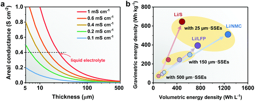
Ideally, SSEs should have high ionic conductivity close to that of a liquid electrolyte (above 10−4 S cm−1 at room temperature) and stable interphases with the electrodes, both of which are crucial for ion conductance, a wide electrochemical window to pair with high-voltage cathodes, and strong mechanical properties to accommodate electrode volume changes during charge/discharge and to suppress Li dendrite growth.3 For practical applications in energy storage, processing convenience and low cost are two major aspects.17 Last but not least, the thickness of the SSE is also a critical parameter which influences the internal resistance and the energy-density of all-solid-state Li batteries (ASSLBs).18–20 The internal resistance depends on the ionic conductance of the SSE and the charge transfer resistance of the electrodes. The ionic conductance (G = σA/l, where G, σ, A, and l represent the ionic conductance, ionic conductivity, surface area and thickness of the SSE, respectively) is inversely proportional to the thickness of the SSE membrane. Higher area-normalized conductance is observed in SSEs with reduced thickness, which originates from the shorter time it takes for ions to transport across SSEs (t = l2/D, where t, l, and D represent the Li+ diffusion time, thickness of the SSE and Li+ diffusion constant, respectively). As shown in Fig. 1a, to achieve the same area-normalized conductance as a liquid electrolyte using a 25 μm separator, the reduction of the thickness is equally important to the increase of the ionic conductivity of SSEs. SSEs with ionic conductivity such as 0.4 mS cm−1 can obtain the same areal conductance as a liquid electrolyte if the thickness of the SSE is reduced to 10 μm. Ideally, if a certain SSE is reduced to 1/4 of its original thickness, the Li+ diffusion time across the SSE will be shortened to 1/16, and the areal conductance will quadruple.
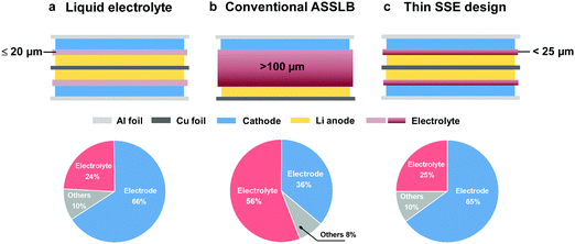
Besides the ionic conductance, the cell-level energy densities of ASSLBs are also inversely related to the thickness of SSEs. The energy densities of Li/LiNi0.8Mn0.1Co0.1O2 (NMC811), Li/S and Li/LiFePO4 (LFP) ASSLBs are calculated based on the pouch cell settings. As illustrated in Fig. 1b, the thickness of the SSE plays an enormous role in determining the cell-level energy densities, and thinner SSEs are essential to achieve higher gravimetric and volumetric energy densities. Unfortunately, conventional SSEs are usually over 100 μm thick, and the excessively large amount of SSE will inevitably offset the advantages of high-energy electrodes. By a rough calculation, if the thickness of the SSE is reduced from 150 to 25 μm (assuming a sulfide SSE with a density of 1.96 g cm−3, and a cathode film containing 80 wt% active materials and 15 wt% SSE), the component ratio of the SSE will decrease from 56 to 25%, which is comparable to that of the liquid electrolyte system (electrolyte amount of 2.5 g A h−1 and cathode active materials of 95 wt%21) (Fig. 2). This corresponds to an over 30% increase in active materials, which contributes to higher energy output. However, the SSE also functions as a separator, and the thinning of the membrane will inevitably deteriorate its mechanical strength and increase the risk of membrane fracture or Li dendrite penetration, both of which lead to internal short circuit, cell failure and even safety hazards. Thus, the challenges associated with the thin SSE design mainly lie in the dilemma between minimizing the thickness and sustaining the mechanical strength.
In this review, we start by briefly introducing the main challenges and recent developments of SSEs. Then we analyze the relationships between the electrolyte thickness and energy density (gravimetric and volumetric energy densities) for various systems. Following that, we focus on the strategies to minimize the thickness of SSE membranes, and highlight the solutions suitable for mass production. In addition, we discuss the recent progress of ASSLBs paired with high-voltage and high-capacity cathodes, and present the potential and challenges of bipolar and flexible ASSLBs. Finally, we conclude by providing perspectives and suggestions towards high energy-density ASSLBs for future commercialization.
2. Fundamental of SSEs
SSEs generally can be classified into 3 categories: solid polymer electrolytes (SPEs), inorganic solid electrolytes (ISEs) and composite polymer electrolytes (CPEs).22,23 SPEs, which consist of a polymer matrix and dissolved lithium salts, have favorable interfacial stability with electrodes, excellent processability, low cost and flexibility, but suffer from low room-temperature (RT) ionic conductivity, inferior electrochemistry stability and unsatisfactory mechanical strength.16 The thickness of most SPEs is in the range of 80 to 200 μm. ISEs are crystalline or glassy inorganics where ion transport relies on their defect sites.24 ISEs possess high ionic conductivity, a broad electrochemical window, and sufficient mechanical strength, but exhibit poor interfacial contacts with electrodes, costly production, low throughput and a lack of flexibility. The widely used powder pressing method produces ISEs up to 1 mm thick. CPEs, which are constructed from an SPE matrix and inorganic fillers, could potentially inherit the advantages of both SPEs and ISEs while overcoming their shortcomings.25 However, most CPEs are over 100 μm thick, and it still remains a huge challenge to greatly reduce the thickness of CPEs without compromising the mechanical properties.2.1 SPEs
SPEs are composed of Li salts dissolved in a polymer matrix, where the optimal polymer presents a high dielectric constant to facilitate the dissociation and transport of ions. Among various polymer matrices such as poly(ethylene oxide) (PEO),26 polyacrylonitrile (PAN),27 poly(vinylidene fluoride) (PVDF),28 poly(propylene carbonate) (PPC)29 and poly(methyl methacrylate) (PMMA),30 PEO is the most researched and widely used one due to its superior solubility for Li salts.31 Under an electrical field, the solvated Li+ hops from one coordination site to another, associated with breaking/forming of Li–O bonds, and long-range Li+ transport is achieved by local relaxation and continuous segmentation rearrangement of the polymer chains (Fig. 3a).32 It is generally believed that ion transport mainly occurs in the amorphous phase of PEO chains, whereas the crystalline phase presents an obstacle for ion transfer. Thus, the ionic conductivity of a PEO-based SPE highly depends on the ratio of the amorphous to crystalline phases. Since PEO is mainly crystalline below the glass transition temperature (tg, ∼65 °C), the ionic conductivity of a PEO-based SPE is quite low at RT (10−7–10−5 S cm−1), restricting it in application in RT batteries. Many strategies have been explored to increase the RT ionic conductivity of PEO-based SPEs, such as polymer architecture optimization,33,34 salt design,35,36 and organic plasticizer37,38 or inorganic filler addition.39,40 Among them, the introduction of a plasticizer or inorganic filler is a facile yet effective approach to increase the motion ability of PEO chains.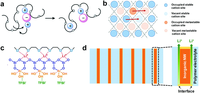 | ||
| Fig. 3 (a) Li+ migration and hopping in the amorphous region of SPEs by polymer segmental motion. Reproduced with permission.32 Copyright 2015, Royal Society of Chemistry. (b) Typical Li+ migration mechanisms in ISEs: vacancy and interstitial. (c) Diagram showing the interaction between fillers, LiTFSI and PEO that leads to decreased PEO crystallinity and ion decoupling. Reproduced with permission.79 Copyright 2017, Elsevier. (d) Possible Li+ conducting pathways in CPEs with aligned nanowires. | ||
Plastic crystals such as succinonitrile (SN) with a dielectric constant as high as 55 exhibit high solubility of Li salts at RT, thus showing considerably higher ionic conductivity than PEO. In 2004, Alarco et al. first discovered that SN with dissolved 5 mol% lithium bis(trifluoromethanesulfonyl)imide (LiTFSI) reaches a RT ionic conductivity as high as 3 × 10⁻³ S cm−1, comparable to that of the liquid electrolyte.41 The electrolyte also shows a broad electrochemical window up to 6 V. Later in 2007, Fan et al. demonstrated SN as a universal plasticizer in SPEs.37 Due to the existence of a highly conductive SN–LiTFSI phase, 50% (PEO–LiTFSI)–50% SN exhibits a conductivity of 5 × 10⁻⁴ S cm−1, 80 times higher than that of the PEO–LiTFSI film at the same temperature. Echeverri et al. systematically and theoretically studied the relationship between ionic conductivity and the coexistence regions of the ternary phase diagram of PEO/LiTFSI/SN.42 SN is found to show dual-functionality as both a good plasticizer and an effective ionizer to dissociate Li+ from the LiTFSI salt. With the optimized design, a high ionic conductivity of 2.9 × 10⁻³ S cm−1 can be achieved at RT. Despite the fact that the introduction of SN brings a significant increase in the RT ionic conductivity, the possible polymerization of nitriles in the presence of metallic Li limits the application of SN-based SPEs in ASSLBs.41,43
Liquid electrolytes and conventional SPEs are dual-ion conductors, where both Li+ cations and the counter anions are mobile. During discharge, the ambipolar conductivity leads to the accumulation of anions on the anode side since electrodes only exchange cations (Li+) with the electrolyte.44 This results in a concentration gradient and electrode polarization, and triggers the growth of dendrites in LMBs. Single Li+ conducting SPEs (SLC-SPEs) have been designed to overcome the challenges of the dual-ion conductors, where anions are immobilized by a polymer matrix, inorganic fillers or anion acceptors, and only Li+ contributes to the flow of charge inside the battery.44–47 Bouchet et al. designed a polyanionic block copolymer electrolyte P(STFSILi)-b-PEO-b-P(STFSILi), which consists of a linear PEO block for ionic conductivity and a graft-diblock P(STFSILi) for mechanical strength and anion immobilization.45 The weak interaction between Li+ and the grafted TFSI anions with delocalized negative charge enables a high dissolution level of Li+. The obtained SLC-SPE exhibits a high tLi+ of 0.85 and ionic conductivity of 1.3 × 10⁻⁵ S cm−1 at 60 °C, enhanced mechanical strength (10 MPa) and a broadened electrochemical stability window up to 5 V, all of which contribute to an impressive improvement in the performance of Li/SLC-SPE/LFP ASSLBs at 60 °C. Lago et al. reported a –SO2N(−)SO2CF3 moiety grafted nano-Al2O3 filler to enable unipolar conductance in a PEO/PEGDME polymer matrix.46 Long-term stability of 130 cycles with a specific capacity of 125 mA h g−1 was achieved in Li/LFP ASSLBs at 70 °C. The unipolar conductivity of the SLC-SPE effectively enhances the ion selectivity and the electrochemical performance of the ASSLBs, however, the unsatisfactory RT ionic conductivity remains a bottleneck for their application.
2.2 ISEs
ISEs can be mainly classified into oxides, including NASICON-type, perovskite-type, garnet-type, etc., and sulfides. Fast ionic conductance can be achieved by ion hopping through vacancies or interstitials (Fig. 3b).3,24,48Na superionic conductor (NASICON)-type ISEs are crystalline phosphates generally with the AM2(PO4)3 formula (A = Li, Na or K; M = Ge, Zr or Ti). Among them, Li1+xAlxTi2−x(PO4)3 (LATP) and Li1+xAlxGe2−x(PO4)3 (LAGP) are widely studied due to their high ionic conductivity at RT.49 The reported ionic conductivity of LATP could reach as high as 1.09 × 10⁻³ S cm−1.50,51 However, NASISON-type ISEs are not stable with Li metal, which hampers their application.52 Li can be introduced into perovskite-type ABO3 (A = La, Sr, or Ca; B = Al or Ti) on the A site, creating a perovskite-type ISE with a general formula of Li3xLa2/3−xTiO3 (LLTO, 0 < x < 0.16).53 The conductivity of LLTO heavily depends on the concentration of both Li+ and vacancies, and with the optimized design, a high RT conductivity of 10−3 S cm−1 can be found in Li0.34La0.56TiO3.54 Similar to NASICON-type ISEs, the reduction from Ti4+ to Ti3+ when in contact with Li metal limits the application of LLTO in ASSLBs.54,55 Unlike NASICON or perovskite-type ISEs, garnet-type ISEs exhibit high chemical stability with Li metal, which makes them an attractive candidate for ASSLBs. The general chemical formula of garnet-type ISEs is A3B2(XO4)3 (A = Ca, Mg, Y, La or rare-earth; B = Al, Fe, Ga, Ge, Mn, Ni, V; X = Si, Ge, Al), where the A, B and X cations are in 8, 6, and 4 coordinated sites, respectively.56 One representative garnet-type ISE is a Li7La3Zr2O12 (LLZO)-based Li-rich material, whose ionic conductivity can reach 3 × 10⁻⁴ S cm−1 at RT.57 A small amount of Ta, Al, Ga, Nb, or Te is doped to further improve the ionic conductivity to ∼10−3 S cm−1. Despite the fact that garnet-type ISEs exhibit high ionic conductivity and a wide electrochemical window, the poor interfacial contact with the Li anode and the sensitivity towards H2O and CO2 significantly decrease their performance.58,59
Unlike the crystalline oxides that are fabricated by high-temperature sintering, glass-ceramic sulfides are usually prepared by low-temperature heat-treatment or liquid phase reactions. The glassy Li2S–SiS2 system was first studied in 1986 and later achieved a RT ionic conductivity of 6.9 × 10⁻⁴ S cm−1 with Li3PO4 doping.60,61 The glass-ceramic type electrolyte in the form of xLi2S–(1 − x)P2S5 has been widely reported to exhibit high ionic conductivity reaching an exceptionally high 10−2 S cm−1 at RT.62 So far, sulfide electrolytes possess the highest ionic conductivity among all SSEs, together with a relatively “soft” contact with electrodes compared to that of the oxides. However, sulfides are extremely sensitive to moisture and generate hazardous H2S gas, which is a major drawback to application in practical batteries.63
2.3 CPEs
Inorganic fillers can be incorporated into SPEs to develop composite polymer electrolytes with the purpose of increasing the ionic conductivity, strengthening the mechanical properties, and improving the interfacial contact with the electrodes. CPEs, which combine the advantages of both SPEs and ISEs, are considered promising to construct high-performance ASSLBs.64,65 The inorganic fillers can be classified as inert (non-ionic conductive) fillers and active fillers (ionic conductive). The enhanced ionic conductivity from the inert fillers mainly comes from the reduced polymer crystallinity to accelerate segmental motion.66,67 The surface groups on the ceramic nanoparticles may also engage in the Lewis acid–base interaction with Li salts or polymer chains to facilitate Li+ dissociation (Fig. 3c).68,69 The active fillers directly participate in the ion transport, leading to additional ionic pathways.70–72Ceramic nanoparticles (5.8–13 nm) were first introduced into a PEO SPE by Croce et al. in 1998.73 The ionic conductivity increases by over 3 orders of magnitude and reaches 2 × 10⁻⁵ S cm−1 at 31 °C, benefiting from the combined effect of large surface area and Lewis-acid characteristics, which prevents the recrystallization of PEO chains during the cooling process (from above 60 °C to ambient temperature). A tLi+ of 0.6 is also achieved, much higher than that of 0.2–0.3 in the ceramic-free PEO electrolyte. Although the addition of nanoparticles is advantageous, nanomaterials with high surface energy tend to aggregate, leading to reduced surface area and deteriorated Li+ pathways. To overcome the agglomeration of nanoparticles, Pan et al. proposed the use of inorganic polyhedral oligomeric silsesquioxane (POSS) to cross-link poly(ethylene glycol) (PEG) and produce a CPE with a controllable network structure.67 Enhancement in both ionic conductivity (∼1 × 10⁻⁴ S cm−1 at RT) and mechanical strength (33.6 MPa) is realized, which is attributed to the suppressed polymer crystallization and the uniformly dispersed POSS nanoparticles in the cross-linked network.
Constructing interconnected filler networks can further improve the ionic conductivity and mechanical strength of CPEs. Lin et al. reported an in situ synthesis of a SiO2-aerogel reinforced CPE with an improved RT ionic conductivity of 6 × 10⁻⁴ S cm−1 and high modulus of 0.43 GPa.74 The ultrafine and continuous SiO2 network with large surface area boosts the Lewis acid–base interaction with anions and enables more efficient Li+ conductance. The strong SiO2 backbone also endows the CPE with excellent mechanical strength, which is beneficial for suppressing Li dendrite growth. A more powerful strategy for fabricating continuous Li+ pathways in CPEs is to adopt 3D fast ion conductor networks. Bae et al. synthesized a 3D nanostructured hydrogel derived pre-percolated Li0.35La0.55TiO3 (LLTO) framework, serving as a 3D nanofiller to prevent agglomeration and provide continuous Li+ conducting pathways.75 The LLTO/PEO CPE reaches a RT ionic conductivity close to 10−4 S cm−1 with improved thermal/electrochemical stability.
The tortuous filler/polymer interface junctions in CPEs present the main hindrances for realizing optimized conductivity. Recently, the concept of a CPE with aligned nanowires has been introduced by Liu et al.76 The vertically aligned Li0.33La0.557TiO3 nanowires (LLTO NWs) significantly enhance the ionic conductivity of the CPE due to its long-term ionic conducting pathway without obstructive cross-junctions (Fig. 3d). The RT ionic conductivity of the CPE with vertically aligned LLTO NWs is ten times higher than the CPE with randomly distributed NWs. Later, Zhai et al. used an ice-templating process to produce a CPE with vertically aligned and continuous Li1+xAlxTi2−x(PO4)3 (LATP) nanoparticles.77 The aligned fast ionic conductors provide direct channels for Li+ transport and improve the RT ionic conductivity to 5.2 × 10⁻⁵ S cm−1, 3.6 times that of the CPE with random LATP nanoparticles. Zhang et al. used a melt infiltration method to introduce a PEO polymer electrolyte into anodized aluminum oxide (AAO) discs and produce vertical, continuous and non-tortuous interfaces.78 The interfacial effects decrease the crystallization temperatures and reduce the crystallinity of PEO to 14.7%, lower than pure SPE (22.7%) and the CPE with NWs (19.7%) at temperatures below crystallization. The CPE exhibits a RT ionic conductivity of 5.82 × 10⁻⁴ S cm−1 and excellent Li dendrite suppression ability.
3. Effects of the SSE thickness on the energy density
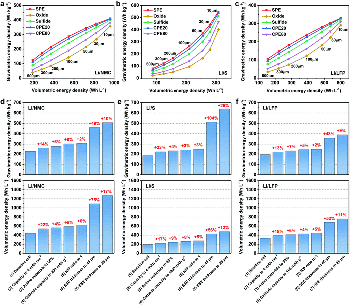
ASSLBs that are expected to power electric vehicles and portable devices require both high gravimetric and volumetric energy densities. To quantify the influence of the SSE thickness on the energy densities, we provide simulations of gravimetric and volumetric energy densities of three types of ASSLBs (Li/NMC811, Li/S and Li/LFP) paired with various SSEs in a practical pouch cell model. A cathode capacity of 3 mA h cm−2 and N/P ratio of 2 are set for all ASSLBs.9,80,81 In practical ASSLBs, it is extremely challenging to reach the theoretical capacities, and thus we reasonably assume stable specific capacities of 170, 1000 and 150 mA h g−1 for the NMC811, S and LFP cathode, respectively.82–85 Furthermore, the cathode active material accounts for 80%, 50% and 80% with a cathode density of 3.0, 0.4 and 2.0 g cm−3 for the NMC811, S and LFP cathode, respectively.86 The cathode active material ratios in solid-state batteries are lower than their counterparts using liquid electrolytes because a non-negligible amount of SSE needs to be incorporated in the cathode film for sufficient ion conduction. A cathode current collector (Al foil, 12 μm, double-sided coated) and other components in pouch cells (taps, laminate film, etc., accounting for 5 wt% of the whole pouch cell) are also included in the calculation.87 PEO, LLZO, double-layered LPS-LGPS and two LLZO/PEO hybrids are chosen as representatives of SPEs, oxide ISEs, sulfide ISEs and CPEs, with the density calculated to be 1.26 (EO![[thin space (1/6-em)]](https://www.rsc.org/images/entities/char_2009.gif) :
:![[thin space (1/6-em)]](https://www.rsc.org/images/entities/char_2009.gif) Li ratio of 10
Li ratio of 10![[thin space (1/6-em)]](https://www.rsc.org/images/entities/char_2009.gif) :
:![[thin space (1/6-em)]](https://www.rsc.org/images/entities/char_2009.gif) 1), 5.1, 1.96, 1.48 (20 wt% LLZO in PEO SPE, denoted as CPE20) and 3.17 g cm−3 (80 wt% LLZO in PEO SPE, denoted as CPE80), respectively.87
1), 5.1, 1.96, 1.48 (20 wt% LLZO in PEO SPE, denoted as CPE20) and 3.17 g cm−3 (80 wt% LLZO in PEO SPE, denoted as CPE80), respectively.87
As shown in Fig. 4a–c, both the gravimetric and volumetric energy densities increase upon a reducing thickness of the SSE. The light-weight SPE and CPE20 are more promising in delivering high gravimetric energy densities compared to the heavy oxide ISE and CPE80. On the other hand, the volumetric energy density is not affected by the different types of SSEs for a given system, since the thicknesses of the electrodes are fixed and the total thickness of a pouch cell is only determined by the thickness of the SSE. Compared to the Li/NMC811 and Li/LFP ASSLBs, the increase in the gravimetric energy density of the Li/S ASSLB is more significant with a reduced SSE thickness. This is because the weight and the weight reduction ratio of the SSE account for a larger portion of the whole pouch cell using the high-capacity and low-density sulfur cathode. For instance, when reducing the thickness of the SSE from 500 to 10 μm in a Li/S pouch cell, weight reductions of 85.5%, 94.6%, 89.6%, 87.2% and 92.6% of the whole pouch cell using the SPE, oxide ISE, sulfide ISE, CPE20 and CPE80 are observed, respectively, which are higher than the cases in Li/NMC811 (70.0%, 89.2%, 78.0%, 73.1% and 84.5% in order) and Li/LFP pouch cells (67.7%, 88.3%, 76.1%, 71.0% and 83.2% in order).
In the Li/NMC811 ASSLB, the gravimetric energy densities using a 10 μm SPE, oxide ISE, sulfide ISE, CPE20 and CPE80 are 410, 358, 399, 407 and 382 W h kg−1, respectively, much higher than using 500 μm SSEs (123, 39, 88, 109 and 59 W h kg−1 in order) (Fig. 4a). However, the gravimetric energy density still falls short of the 500 W h kg−1 target. Fig. 4d illustrates the feasible pathways under different scenarios to achieve the targets of 500 W h kg−1 in gravimetric energy density and 1000 W h L−1 in volumetric energy density. We start with the Li/NMC811 ASSLB employing a conventional 150 μm thick CPE20, and the baseline cell delivers energy densities of 229 W h kg−1 and 441 W h L−1. With the optimized cathode design and the reduced N/P ratio, the energy densities reach 308 W h kg−1 and 622 W h L−1. The gravimetric energy density further increases to 459 and 507 W h kg−1 by reducing the thickness of the SSE to 45 and 25 μm, respectively. At the same time, high volumetric energy densities of 1089 and 1271 W h L−1 are achieved using 45 and 25 μm CPE20, respectively. Similar calculations can be made for the other types of SSEs. Generally speaking, to achieve a gravimetric energy density above 500 W h kg−1 in Li/NMC811 ASSLBs, the thickness of the SSEs should be controlled below 30 μm for the SPE, 25 μm for CPE20, 20 μm for the sulfide ISE, and 10 μm for the oxide ISE and CPE80.
As for Li/S ASSLBs, it is possible to realize a gravimetric energy density >500 W h kg−1 with a 10 μm SPE or CPE20 (Fig. 4b). After electrode optimization, 45 μm CPE20 would be sufficient for an output of 512 W h kg−1 (Fig. 4e). Similarly, a 55 μm SPE, 35 μm sulfide ISE, 25 μm CPE80 and 15 μm oxide ISE are necessary to reach the target of 500 W h kg−1. On the other hand, the volumetric energy density of Li/S ASSLBs is relatively low and a 25 μm SSE only leads to an output of 473 W h L−1, which originates from the high porosity and low density of the S cathode. Finally, for Li/LFP ASSLBs, it is unlikely to deliver a high gravimetric energy density of 500 W h kg−1 due to the relatively low capacity of the LFP cathode (Fig. 4f). However, a high volumetric energy density of 755 W h L−1 is obtained with a 25 μm thick SSE, and it can further increase to above 800 W h L−1 as the thickness is reduced to 15 μm. It should be noted that some parameters in the calculation are quite challenging to reach in practice, so the requirement on the SSE thickness should be more stringent for practical ASSLBs. Nevertheless, the development of ultrathin SSEs is essential for the realization of high-energy-density ASSLBs.
4. Strategies to reduce the thickness of SSEs
As discussed previously, the internal resistance and gravimetric/volumetric energy densities of ASSLBs are greatly dependent on the thickness of the SSE. The internal resistance is determined by the ionic conductance of the SSE and the charge transfer resistance of the electrodes. The ionic conductance, by definition, is inversely proportional to the thickness of the SSE membrane. Fig. 5a shows the conductance and thickness of SSEs in recent publications. Although the reported SSEs have a wide range of ionic conductivities (10−6–10−4 S cm−1 at RT), the conductance in general becomes lower as the thickness increases. Similar trends can be observed in the cell-level energy density vs. SSE thickness data (Fig. 5b), which highlights the importance of minimizing the thickness of the SSE. Unfortunately, the thickness of ISEs produced by the widely used powder-pressing method is up to 1 mm, while SPEs and CPEs are relatively thinner, with thicknesses generally ranging from 80 to 200 μm, which are still far too thick to achieve the target gravimetric/volumetric energy densities.88 On the other hand, SSEs not only function as ionic conductors but also serve as separators to avoid contact between the cathode and anode. Reducing the thickness of the SSE is accomplished by increasing the risks of internal short-circuit due to the mechanical failure of SSEs. Thus, a balance needs to be found between minimizing the thickness and sustaining the mechanical integrity of SSEs. In recent years, a number of strategies have been employed to successfully produce thin SSE membranes with sufficient mechanical strength, such as supporting SSEs with scaffolds, developing tape casting techniques, and utilizing emerging strategies such as 3D printing. The traditional thin-film deposition-based fabrication techniques are too expensive and time-consuming to be scaled-up in manufacturing, and are not in the scope of this review.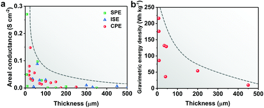 | ||
| Fig. 5 (a) The thickness of SSEs and the corresponding area-normalized ionic conductance in the literature: SPEs,20,78,89–96 ISEs,97–105 and CPEs.67,69,83,106–115 (b) The thickness of SSEs and the corresponding gravimetric energy densities in reported Li/LFP ASSLBs.20,39,90,100,102,108,110,116 | ||
4.1 Scaffold supports
Infiltrating solid electrolytes into porous scaffolds is an effective strategy to fabricate thin SSEs with enhanced mechanical stability. The robust and flexible scaffold provides mechanical support for the soft polymer electrolyte or brittle ceramics and suppresses Li dendrite growth during cycling even with reduced SSE thickness. The thickness of the resulting SSE is governed by the thickness of the scaffold (Table 1).In 2014, Choi et al. reported a new class of thin and deformable plastic crystal SPEs by combining PEO/SN with a porous polyethylene terephthalate (PET) nonwoven.18 The 3D plastic crystal CPE is formed by in situ UV polymerization of ethoxylated trimethylolpropane triacrylate (ETPTA) monomer inside a PET scaffold in the presence of plastic crystal SN (N-PCPE). The highly porous (∼70% porosity) and thin (thickness ∼13 μm) PET is composed of multi-fibrous layers with interconnected and large-sized pores (more than 5 μm), which contributes to the well-developed 3D continuous ionic pathway. The ionic conductance of N-PCPE is 5.7 × 10⁻⁴ S cm−1 at 30 °C, slightly lower than that of the control CPE containing the UV-crosslinked ETPTA/SN SPE without a PET scaffold (X-PCPE) due to the presence of the non-ionic conductive PET matrix. However, the thin N-PCPE (25 μm) is advantageous in delivering an ionic conductance (0.38 S at 30 °C) more than twice that of the thick X-PCPE (0.18 S at 30 °C, thickness 200 μm), owning to a much shorter Li+ diffusion distance. The resulting Li4Ti5O12 (LTO)/LiCoO2 (LCO) solid-state battery achieves stable cycling at a high current density of 2C at 30 °C. Moreover, N-PCPE shows great tolerance to bending stress and the pouch cell employing N-PCPE can light a LED bulb and maintain stable cycling under serious deformation. Later, an even thinner plastic crystal SPE of 17 μm was fabricated by in situ polymerization on an electrospun PAN fiber membrane.19 The molten precursor of PVA–CN, SN and Li salts were injected into the PAN mat and filled into the cells, and then the as-prepared cells were heated at 70 °C, which prepares the cross-linked SPE (SEN) and forms ASSLBs in one step (Fig. 6a). The PAN mat ensures sufficient mechanical strength and the obtained SEN shows enhanced stress and strain compared to the counterpart PVA–CN/SN without PAN backbones (thickness of 150 μm) (Fig. 6b). The 17 μm SEN exhibits a RT conductance of 0.30 S, which is even higher than that of the liquid electrolyte (0.25 S) because of the remarkably reduced membrane thickness (Fig. 6c). The RT electrochemical performance of Li/LFP using SEN is comparable to the cell using a liquid electrolyte. Recently, Jiang et al. pressed Li6.75La3Zr1.75Ta0.25O12 (LLZTO) powders connected by fibrous polytetrafluoroethylene (PTFE) into a nylon mesh and then immersed the SSE into a melted SN/LiTFSI mixture to obtain a thin (100 μm), robust and flexible CPE with a high RT ionic conductivity of 1.2 × 10⁻⁴ S cm−1 and stable cycling in both Li/LFP and Li/NMC ASSLBs.117
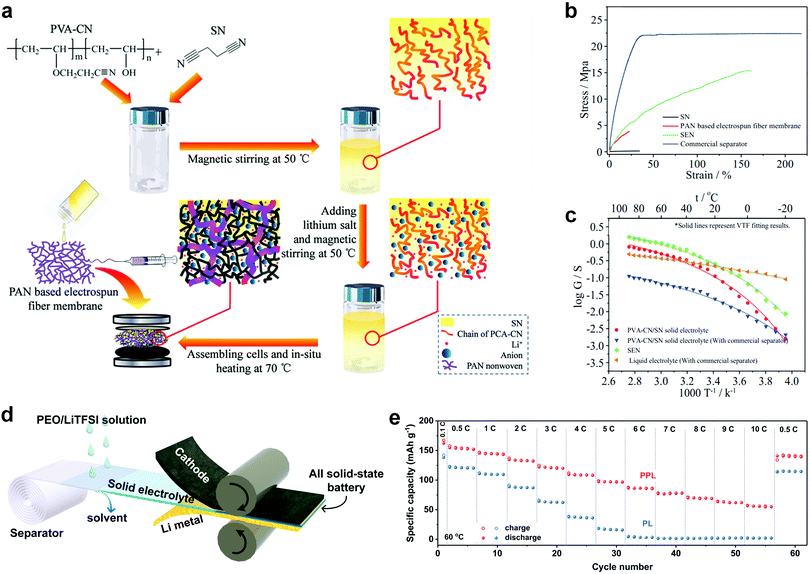 | ||
| Fig. 6 (a) Schematic illustration of the in situ synthesis of SEN. (b) Stress–strain curves of SEN, the PAN membrane and the commercial separator. (c) Ionic conductance comparison of SEN with a PVA–CN/SN solid electrolyte and liquid electrolyte. Reproduced with permission.19 Copyright 2015, Wiley-VCH Verlag GmbH & Co. KGaA. (d) Schematic illustration of the roll-to-roll process that can be adopted to assemble ASSLBs with PPL electrolyte. (e) Rate performance of the PPL electrolyte at 60 °C. Reproduced with permission.90 Copyright 2019, Wiley-VCH Verlag GmbH & Co. KGaA. | ||
Commercially available polyolefin separators, which are highly porous, mechanically strong and flexible, chemically stable and cost-efficient, are a promising candidate as the scaffold for thin SSEs. A thin (36 μm) and asymmetric organic–inorganic hybrid solid electrolyte (ASE) was developed by Duan et al. using a separator as the scaffold.107In situ polymerization of poly(ethylene glycol) methyl ether acrylate (PEGMEA) in the interior and on the cathode side of the separator enables good interfacial contact, whereas an Li7La3Zr2O12 (LLZO) layer topped with a thin polymer electrolyte layer facing the anode side prevents Li dendrite penetration. The total thickness of the soft polymer electrolyte is about 30.4 μm, including 5.4 μm on the exterior and 25 μm impregnated in the pores of the separator, and the thickness of the dense LLZO layer is about 5.7 μm. The ASE exhibits an ionic conductivity of 1 × 10⁻⁴ S cm−1 at 55 °C and a broad electrochemical window up to 4.8 V. Wu et al. fabricated an ultrathin polymer electrolyte (7.5 μm) by integrating a polyethylene (PE) separator with a PEO polymer electrolyte (PPL) (Fig. 6d).90 The robust yet flexible polyethylene separator offers mechanical support for the soft PEO electrolyte, effectively preventing short-circuits even under mechanical deformation. PPL exhibits a Young's modulus of 445 MPa, more than three orders higher than that of the thick PEO SPE without separator support, and the ultrathin membrane maintains structural integrity after a bending test of 10![[thin space (1/6-em)]](https://www.rsc.org/images/entities/char_2009.gif) 000 cycles. Due to the reduced internal resistance, the Li/LFP ASSLB with the ultrathin PPL can successfully cycle at a current density as high as 10C at 60 °C (Fig. 6e), outperforming that of the thicker CPE (∼27 μm) with a similar structure. The results demonstrate that the battery performance can be significantly improved by minimizing the SSE thickness without changing the ionic conductivity. Adopting battery separators as the scaffold promotes the possibility of roll-to-roll assembly, which is a big step forwards in industrial fabrication of ASSLBs. However, the thermal stability of polyolefin separators needs further improvement to enable safe ASSLBs in a wider temperature window.
000 cycles. Due to the reduced internal resistance, the Li/LFP ASSLB with the ultrathin PPL can successfully cycle at a current density as high as 10C at 60 °C (Fig. 6e), outperforming that of the thicker CPE (∼27 μm) with a similar structure. The results demonstrate that the battery performance can be significantly improved by minimizing the SSE thickness without changing the ionic conductivity. Adopting battery separators as the scaffold promotes the possibility of roll-to-roll assembly, which is a big step forwards in industrial fabrication of ASSLBs. However, the thermal stability of polyolefin separators needs further improvement to enable safe ASSLBs in a wider temperature window.
Porous polyimide (PI) films with excellent heat resistance can be prepared by methods such as electrospinning, track-etching, phase inversion and so on.20,91,106 Hu et al. infiltrated Li6.75La3Zr1.75Ta0.25O12 (LLTZO)/PVDF slurry into an electrospun PI fiber network and prepared a 20 μm-thick LLTZO/PVDF/PI solid electrolyte.106 The thin SSE presents improved electrochemical and thermal stabilities, and can be stably cycled with a Li/NMC battery in a voltage window of 2.5–4.3 V. Wan et al. prepared an 8.6 μm-thick SSE made of a PI host with vertically aligned nanopores and PEO polymer electrolyte fillers.20 Molecular simulation reveals that Li+ diffuses faster along the aligned direction, with a calculated diffusion coefficient in the aligned direction of 1.3 × 10⁻⁸ cm2 s−1, high than that of 5.7× 10⁻⁹ cm2 s−1 in the random direction. The increased ionic conductivity in aligned nanopores is probably due to the nanoconfinement of channels and/or polymer-chain alignment at the PI/PEO interfaces. Li/LFP ASSLBs show stable cycling for 200 cycles at 60 °C, and over 120 mA h g−1 capacity at 40 and 30 °C. This work demonstrates that ultrathin SSEs with vertically aligned ion channels are promising for achieving high-performance ASSLBs. Unfortunately, the porosity of the PI film made by the track-etching method is only 11%. Strategies to fabricate polymer hosts with a large number of vertically aligned channels need to be explored.
Other than polymer-based electrolytes, ductile sulfides can also be assembled into thin films with mechanical support of a scaffold. Nam et al. prepared a thin (∼70 μm) and bendable sulfide ISE reinforced with a mechanically compliant poly(paraphenylene terephthalamide) (PPTA) nonwoven (NW) scaffold (Fig. 7a).98 Sulfide slurry [Li3PS4 (LPS) or Li10GeP2S12 (LGPS) in anhydrous toluene] was coated on Ni foil using a doctor-blade, followed by solvent evaporation. The sulfide layer was then cold-pressed into a 16 μm-NW substrate with a high porosity of 70% and large opening sizes (∼40 μm). Although the resulting NW-SSE film exhibits lower RT ionic conductivity (2 × 10⁻⁵ S cm−1) compared to the conventional sulfides (7 × 10⁻⁵ S cm−1, 700 μm thick), due to the presence of nonionic-conducting NWs, it demonstrates a three-fold improvement in conductance, i.e. 37 vs. 14 mS. The flexible sulfide electrolyte can be both free-standing and bendable, enabling a bipolar cell architecture, which further improves the energy densities of ASSLBs. Later, a 40 μm thick sulfide ISE supported by electrospun PI nonwovens was reported by Kim et al. (Fig. 7b).118 Solution processable Li6PS5[Cl,Br] was dropped onto a PI nonwoven, followed by drying under a vacuum and further heat treatment at 400 °C to enhance the crystallinity. The considerably thinner and lighter PI-LPSClBr (40–70 μm) exhibits an ionic conductance of 15–29 mS, similar to that of the conventional Li6PS5Cl0.5Br0.5 pellet (700 μm thick, 29 mS) (Fig. 7c), which gives rise to a significant advantage in the cell-based energy density of ASSLBs (Fig. 7d).
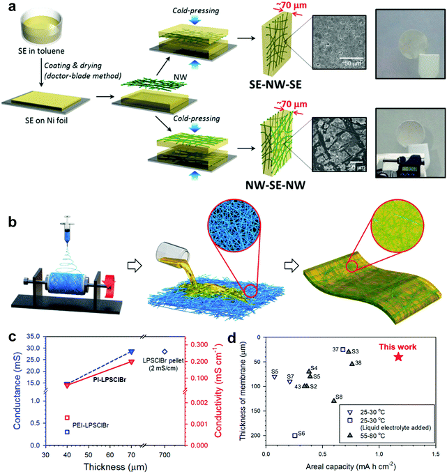 | ||
| Fig. 7 (a) Schematic illustrating the synthesis of the bendable sulfide NW-SE films with two different structures. Reproduced with permission.98 Copyright 2015, American Chemical Society. (b) Schematic showing the fabrication of the PI-supported Li6PS5[Cl,Br] membranes. (c) Conductance of PI-Li6PS5Cl0.5Br0.5 as a function of membrane thickness. (d) Comparison of the SSE membrane thickness and areal capacity for NMC/graphite all-solid-state batteries. Reproduced with permission.118 Copyright 2020, American Chemical Society. | ||
Minimized thickness, mechanical reliability, and good adhesion with the solid electrolyte are crucial characteristics of the scaffold to achieve thin SSEs with favorable ionic conductance and ASSLBs with high energy density. The chemical, electrochemical and thermal stabilities of the scaffold are also important parameters for SSEs. Porous polymers with remarkable mechanical strength are a popular matrix to construct SSEs with thickness even lower than 10 μm. High porosity and interconnected pore structure are required due to the poor ionic conducting nature of the polymer matrix. An ionic conducting inorganic network provides additional ion pathways with a sacrifice in mechanical strength, which leads to relatively thicker SSEs above 40 μm. For practical application, the possibility of roll-to-roll manufacture is desirable to allow for the implementation of sheet-like thin SSEs in the existing LIB production lines. In this regard, adopting commercially available porous polymer scaffolds offers opportunities for fast and scalable manufacturing of thin SSEs at a low-cost. Although large-area ceramic precursor films can be obtained by electrospinning or employing templates, the ceramic network after sintering is not robust enough to stand roll-pressing, which leads to limited scalability and a major challenge for practical application of this method.
| SSE composition | Fabrication method | SSE thickness (μm) | RT ionic conductivity (S cm−1) | Active materials | Electrochemical performance | Ref. |
|---|---|---|---|---|---|---|
| “—” means data not available. | ||||||
| ETPTA/SN | In situ polymerization on PET fibers | 25 | 5.7 × 10⁻⁴ | LTO/LCO | 128 mA h g−1 (0.2C, RT) | 18 |
| PVA–CN/SN | In situ polymerization on PAN fibers | 17 | 4.5 × 10⁻⁴ | Li/LFP | 155 mA h g−1 (0.1C, RT) | 19 |
| C-PEGDE | In situ polymerization on cellulose fibers | 30 | 8.9 × 10⁻⁵ | Li/LFP | 135 mA h g−1 (0.05C, RT) | 89 |
| PVDF/HEC/EC-DEC | Dip coating onto a PP separator | 16 | 7.8 × 10⁻⁴ | Li/LNMO | 133 mA h g−1 (0.2C, RT) | 119 |
| PEO | Solution infiltration into a PE separator | 7.5 | 3.7 × 10⁻⁵ | Li/LFP | 160 mA h g−1 (0.1C, 60 °C) 135 mA h g−1 (0.1C, 30 °C) | 90 |
| PEO | Melt infiltration to a PI film | 8.5 | 2.3 × 10⁻⁴ | Li/LFP | 176 mA h g−1 (0.1C, 60 °C) 150 mA h g−1 (0.1C, 30 °C) | 20 |
| PEO | Melt infiltration to PI fibers | 10 | 6.7 × 10⁻⁶ | Li/LFP | 163 mA h g−1 (0.1C, 60 °C) | 91 |
| PEO/SN | Solution infiltration to cellulose | 55 | 5 × 10⁻⁴ | Li/LCO | 152 mA h g−1 (0.1C, 60 °C) | 120 |
| PEO | Melt infiltration to AAO | 60 | 5.82 × 10⁻⁴ | — | — | 78 |
| LLZTO/PVDF | Infiltration to PI fibers | 20 | 1.23 × 10⁻⁴ | Li/NMC | 160 mA h g−1 (0.1C, RT) | 106 |
| LLZTO/PTFE/SN | Hot pressing into Nylon mesh | 100 | 1.2 × 10⁻⁴ | Li/LFP | 157 mA h g−1 (0.1C, RT) | 117 |
| LLZO/PEO (asymmetric) | In situ polymerization/tape casting on a PP separator | 36 | 1 × 10⁻⁴ | Li/LFP | 161 mA h g−1 (0.2C, 55 °C) | 107 |
| LPS | Infiltration to Kevlar fibers | 100 | 3 × 10⁻⁴ | Li/Li2S | 800 mA h g−1 (0.05C, RT) | 97 |
| LPS | Cold pressing into PPTA NWs | 70 | 2 × 10⁻⁴ | LTO/LCO | 140 mA h g−1 (0.4C, RT) | 98 |
| LPS[Cl,Br] | Infiltration to PI fibers | 70 | 2 × 10⁻⁴ | Graphite/NMC | 146 mA h g−1 (0.1C, RT) | 118 |
| β-Li3PS4-S | Infiltration to Kevlar fibers | 60 | 2 × 10⁻⁵ | Li–In/LNO-NCA | 156 mA h g−1 (18 mA g−1, 60 °C) | 121 |
| LLZO/PEO | Infiltration to a LLZO network | 40–50 | 2.5 × 10⁻⁴ | — | — | 110 |
| c-LLZO/PEO | Infiltration to a LLZO network | 70–100 | 1.12 × 10⁻⁴ | — | — | 112 |
4.2 Tape casting
Tape casting is a well-established technique to produce films with tailored thickness on a large scale.122–124 Ceramic or polymer powder and necessary additives are dispersed in a solvent to form a pseudoplastic slurry which is then cast onto a release film or directly on the electrode by a doctor blade.125,126 By adjusting the slurry composition and height of the scraper, the thickness of the SSE can be precisely controlled from a few micrometers to 1 mm (Table 2).![[thin space (1/6-em)]](https://www.rsc.org/images/entities/char_2009.gif) :
:![[thin space (1/6-em)]](https://www.rsc.org/images/entities/char_2009.gif) poly(propylene carbonate) (PPC) = 100
poly(propylene carbonate) (PPC) = 100![[thin space (1/6-em)]](https://www.rsc.org/images/entities/char_2009.gif) :
:![[thin space (1/6-em)]](https://www.rsc.org/images/entities/char_2009.gif) 3 w/w in anisole) was directly coated on the NMC cathode by Yamamoto et al. (Fig. 8b and c).99 After heat treatment at 225 °C for 30 min under a vacuum to remove the ion-blocking PPC binder, the ionic conductivity of the LPS ISE reaches 5.2 × 10⁻⁴ S cm−1. The sheet-like NMC battery with a 59 μm thick ISE layer can stably cycle for 350 cycles and post-mortem SEM analysis shows that the dense ISE layer maintains intimate contact with both electrodes (Fig. 8d and e). In 2019, Chen et al. fabricated a cathode-supported PEO/Al2O3 CPE with a thickness of 19 μm by bilayer tape casting (Fig. 8f).108 The cathode layer and the electrolyte layer are well integrated with tight contact, which reduces the interfacial resistance and enhances Li+ transport through the solid-state battery. The Li/LFP ASSLB exhibits an initial capacity of 125 mA h g−1 and 78% capacity retention after 410 cycles at 30 °C and 0.1C. As the temperature increases to 50 °C, a discharge capacity of 167 mA h g−1 can be achieved at 0.1C.
3 w/w in anisole) was directly coated on the NMC cathode by Yamamoto et al. (Fig. 8b and c).99 After heat treatment at 225 °C for 30 min under a vacuum to remove the ion-blocking PPC binder, the ionic conductivity of the LPS ISE reaches 5.2 × 10⁻⁴ S cm−1. The sheet-like NMC battery with a 59 μm thick ISE layer can stably cycle for 350 cycles and post-mortem SEM analysis shows that the dense ISE layer maintains intimate contact with both electrodes (Fig. 8d and e). In 2019, Chen et al. fabricated a cathode-supported PEO/Al2O3 CPE with a thickness of 19 μm by bilayer tape casting (Fig. 8f).108 The cathode layer and the electrolyte layer are well integrated with tight contact, which reduces the interfacial resistance and enhances Li+ transport through the solid-state battery. The Li/LFP ASSLB exhibits an initial capacity of 125 mA h g−1 and 78% capacity retention after 410 cycles at 30 °C and 0.1C. As the temperature increases to 50 °C, a discharge capacity of 167 mA h g−1 can be achieved at 0.1C.
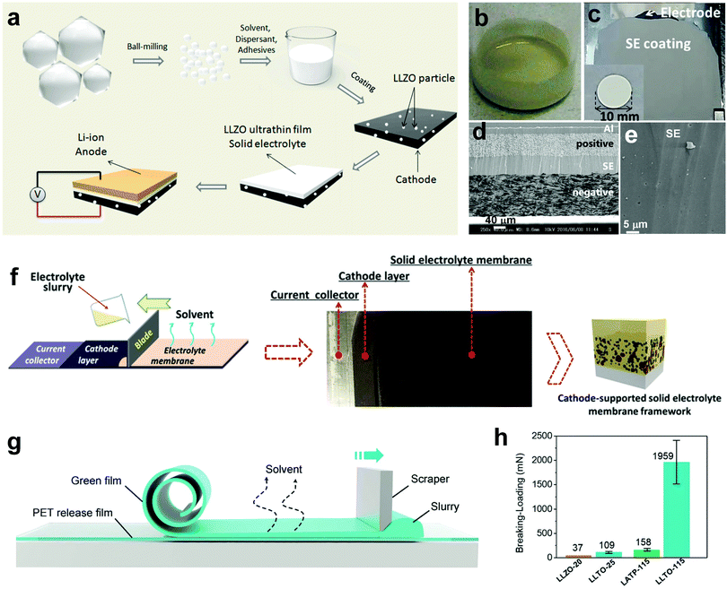 | ||
| Fig. 8 (a) Schematic illustrating the synthesis of the cathode-supported LLZO ultrathin film. Reproduced with permission.127 Copyright 2017, American Chemical Society. Photographs of (b) a LPS-PPC slurry and (c) a cathode-supported LPS electrolyte. (d) Cross-sectional SEM image of the NMC–graphite full cell employing the LPS electrolyte after 350 cycles, and (e) the magnified figure of the LPS electrolyte layer. Reproduced with permission.99 Copyright 2017, Nature Publishing Group. (f) Schematic illustrating the preparation of the cathode-supported PEO/Al2O3 CPE. Reproduced with permission.108 Royal Society of Chemistry. (g) Schematic showing the fabrication of the LLZO film using the tape-casting method. (h) Breaking force of oxide films with different thicknesses. Reproduced with permission.100 Copyright 2019, Wiley-VCH Verlag GmbH & Co. KGaA. | ||
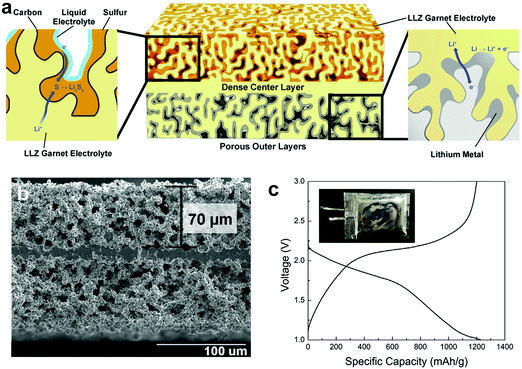 | ||
| Fig. 9 (a) Schematic of the garnet trilayer framework. (b) Cross-sectional SEM image of the garnet trilayer electrolyte. (c) The voltage profiles of a Li–S pouch cell with a sulfur loading of 5.3 mg cm−2 and a lithium loading of 5.4 mg cm−2 at 0.22 mA cm−2. Reproduced with permission.129 Copyright 2019, Elsevier. | ||
Tape casting is a facile and industry-compatible technique to produce large-area solid-state sheets. The thickness of the electrolyte layer can be fine-tuned by adjusting the slurry composition and scraper height. Cathode-supported SSE layers as thin as a few micrometers can be achieved by casting the electrolyte slurry on top of the cathode layer. Cathode-supported SSEs are usually blessed with good electrode/electrolyte contact and sufficient flexibility, whereas they are at risk of interlayer-mixing during slurry casting of the top layer. Freestanding SSE layers prevent possible interlayer-mixing and possess stronger mechanical properties. However, since the mechanical strength deteriorates quickly with reduced thickness, freestanding SSEs are usually thicker than cathode-supported ones. Smart electrolyte configurations such as a bilayer or trilayer architecture are developed to provide mechanical support for the ultrathin electrolyte layer with the help of a porous top-layer which also serves as a host for high electrode material loading. The combination of a thin SSE and thick electrode leads to a significant improvement in energy density.
| SSE composition | SSE architecture | SSE thickness (μm) | RT ionic conductivity (S cm−1) | Active materials | Electrochemical performance | Ref. |
|---|---|---|---|---|---|---|
| “—” means data not available. | ||||||
| PEO/PVDF/Al2O3 | Cathode-supported | 19 | ∼9 × 10⁻⁵ | Li/LFP | 125 mA h g−1 (0.1C, RT) | 108 |
| LLTO/PEO | Cathode-supported | 15 | 2.3 × 10⁻⁴ | Li/S | 415 mA h g−1 (0.05C, RT) | 134 |
| LLZO/PEO | Cathode-supported | 20–75 | 1.6 × 10⁻⁴ (60 °C) | Li/S | 900 mA h g−1 (0.05 mA cm−2, 37 °C) | 84 |
| PEO/ZrO2-IL | Cathode-supported | 20–30 | 8.5 × 10⁻⁵ | Li/S | 600 mA h g−1 (37 °C) | 69 |
| LLZ/PAN/PC-DEC | Cathode-supported | 3 | 6.0 × 10⁻⁴ | LTO/LMFP | 14 mA h (1C, RT) | 135 |
| LPS/PEG–Ti | Cathode-supported | ∼20 | 1.6 × 10⁻⁴ | Li/LFP | 125 mA h g−1 (0.05C, RT) | 109 |
| LLZO | Cathode-supported | 3–5 | 2.4 × 10⁻³ | Li/LFP | 160 mA h g−1 (0.1C, RT) | 127 |
| LPS | Cathode-supported | 59 | 5.2 × 10⁻⁴ | Li/NMC | 155 mA h g−1 (0.17C, RT) | 99 |
| LLZTO/PEO | Freestanding | 30 | 1.12 × 10⁻⁵ | Li/LFP | 155 mA h g−1 (0.1C, 60 °C) | 39 |
| LAGP-PAN | Freestanding | 25 | 3.7 × 10⁻⁴ | Li/NMC622 | 175 mA h g−1 (0.1C. RT); 175 mA h g−1 (0.5C, RT) | 83 |
| Li/NMC811 | ||||||
| LLZO | Freestanding | 41 | 2 × 10⁻⁵ | Li/LFP | 150 mA h g−1 (0.1C, RT) | 100 |
| LAGP | Freestanding | 70 | 2 × 10⁻⁵ | — | — | 136 |
| LATP | Bilayer | 36 | 1.2 × 10⁻⁴ | Li/O2 | 14![[thin space (1/6-em)]](https://www.rsc.org/images/entities/char_2009.gif) 200 mA h g−1 carbon (0.15 mA cm−2, RT) 200 mA h g−1 carbon (0.15 mA cm−2, RT) |
101 |
| LLCZNO | Bilayer | 20 | — | Li/S | 645 mA h g−1 (0.2 mA cm−2, RT) | 128 |
| LLCZN | Trilayer | 28 | — | — | — | 130 |
| LLZ | Trilayer | 14 | — | Li/S | 1244 mA h g−1 (0.22 mA cm−2, RT) | 129 |
4.3 Other strategies
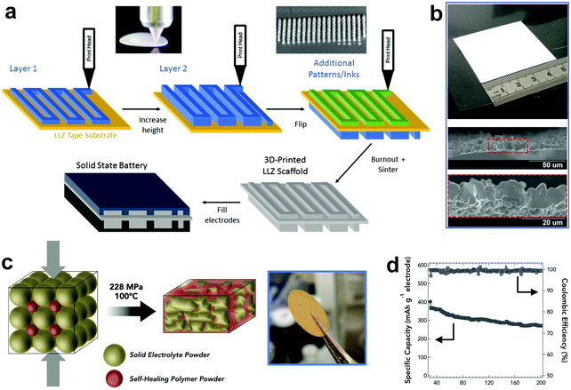 | ||
| Fig. 10 (a) Schematic showing the fabrication process of 3D-printed SSEs. (b) Photograph of a 3D-printed SSE thin film and the cross-sectional SEM image of the 3D-printed thin film with 5–10 μm thickness after sintering. Reproduced with permission.139 Copyright 2018, WILEY-VCH Verlag GmbH & Co. KGaA. (c) Schematic illustrating the formation of L2S–P2S5 in a polymer membrane. (d) Cycling performance of FeS2/Li–In alloy batteries employing the L2S–P2S5 in polymer SSE. Reproduced with permission.140 Copyright 2015, WILEY-VCH Verlag GmbH & Co. KGaA. | ||
SSEs with minimized thickness not only alleviate the battery resistance, but also boost the energy density of ASSLBs. However, the dilemma between the thickness and the mechanical properties of SSEs has not been fully solved. It is still challenging to synthesize thin SSE membranes with sufficient mechanical strength and favorable ionic conductivity. Moreover, the scale-up from laboratory research to industrial mass production of thin SSEs requires convenient fabrication at a cost-effective price. In this regard, a solution-based casting process which possesses a similar fashion to the conventional LIB manufacturing is most promising for large-scale production. Continuous processes that are adoptable in current LIB fabrication, such as the roll-to-roll process, are highly desirable.
5. Applications of thin SSEs in ASSLBs
5.1 High-voltage lithium-metal batteries
Coupling the Li metal anode with high-voltage cathodes such as NMC is a promising approach to maximize the energy density of LMBs.142–145 Due to the low oxidative stability of PEO, PEO-based electrolytes decompose at voltages higher than 3.9 V (vs. Li/Li+), which limits their use to cathodes with lower-voltages such as LFP.14,120 Crosslinking PEO with inorganic or organic components can effectively broaden the electrochemical window of PEO-based electrolytes, however, the majority of the reported studies are still applied in LFP batteries. An in situ hydrolysis of tetraethyl orthosilicate (TEOS) in PEO solution was proposed by Lin et al. to synthesize a PEO/monodisperse ultrafine SiO2 CPE, which has outstanding 5.5 V vs. Li+/Li voltage stability.116 Xu et al. prepared a PEO/perovskite-type Li3/8Sr7/16Ta3/4Zr1/4O3 CPE with strong bonds between TFSI anions and ceramic fillers and increased the electrochemical window of the SSE to a higher voltage over 5 V.70 Besides fillers, electrolyte additives such as lithium borates (typically lithium bis(oxalato)borate (LiBOB), and lithium difluoro(oxalate)borate (LiDFOB)) that increase the oxidation resistance of liquid electrolytes are readily transferable to SSEs by forming a more robust cathode–electrolyte interphase.120,146,147Polymers such as PAN, PVDF, PVDF–HFP, and poly(ionic liquid) (PIL) have higher antioxidation ability, and are compatible with high-voltage cathodes. Ma et al. prepared a polyethylene supported ultrathin PVDF/hydroxyethyl cellulose (PVDF/HEC) polymer electrolyte by dipping a PE separator in a coating solution.119 The resulting polymer electrolyte (16 μm) was then soaked in liquid electrolyte to obtain a gel polymer electrolyte with oxidation stability up to 5.25 V, far higher than the 4.3 V of the liquid electrolyte. The Li/LiNi0.5Mn1.5O4 cell cycled between 3.5 and 5 V exhibits a high initial discharge capacity of 133 mA h g−1 and stable cycling with 88% retention after 200 cycles at 0.2C. Dong et al. prepared an ultra-strong bacterial cellulose supported poly(methyl vinyl ether-alt-maleic anhydride) plus propylene carbonate/lithium difluoro(oxalato) borate multifunctional gel polymer electrolyte (∼80 μm) which demonstrates superior electro-oxidative resistance (5.2 V vs. Li+/Li) and ultra-long cycle life in a 4.45 V-class Li/LCO battery.146 Although the aforementioned polymers are oxidation-resistant, the ionic conductivities in those dry polymers are too limited to compete with PEO, so a large amount of liquid additives needs to be included, which contradicts the safety benefits brought by SSEs. Moreover, some antioxidative polymers such as PAN are not compatible with the Li metal anode due to severe side reactions.
The asymmetrical design of SSEs that optimizes the compatibility with both the high-voltage cathode and Li anode and provides sufficient ionic conductivity is investigated by researchers. Zhou et al. first investigated a bilayer polymer electrolyte with a high-voltage stable layer of poly(N-methyl-malonic amide) (PMA) contacting the cathode and a low-voltage stable layer of PEO contacting the anode side (Fig. 11a).148 In this bilayer structure, the PMA layer is isolated by the PEO layer to avoid reduction by metallic Li, and the PEO layer is protected by the PMA layer from high-voltage oxidation. The 120–130 μm-thick bilayer SPE has a wide redox window of 4.75 V (Fig. 11b), a good ionic conductivity of 2.05 × 10⁻⁴ S cm−1 at 65 °C and high flexibility. The Li/LCO ASSLB cycled in a voltage window of 2.5–4.25 V exhibits a capacity retention of 108.5 mA h g−1 at 0.2C after 100 cycles and 65 °C, corresponding to a retention rate of 91.2% (Fig. 11c). Duan et al. fabricated an asymmetric PAN@LAGP CPE with PAN enriched on one side while LAGP on the other side, due to the different solvent evaporation rate on the two sides of the electrolyte (Fig. 11d).83 Oxidation-resistant PAN and reduction-tolerant PEGDA are then coated on the opposite sides of the CPE, forming a heterogeneous multilayered composite solid electrolyte (HMSE) as thin as 25 μm. The PAN layer on the PAN-rich side provides good electrolyte/cathode compatibility and the PEGDA layer contacting the LAGP-rich side enables stability with the Li anode. The HMSE has a broad electrochemical window of 0–5 V (Fig. 11e), and high RT ionic conductivity of 3.7 × 10⁻⁴ S cm−1, and can be stably cycled with both NMC811 and NMC622 cathodes in a voltage window of 2.8 to 4.3 V (Fig. 11f). Later, the same group constructed Janus interfaces of a ceramic electrolyte by coating PAN and PEO polymer electrolytes on opposite sides of a Li1.4Al0.4Ti1.6(PO4)3 (LATP) pallet.149 The upper PAN (15 μm) facing the NMC622 cathode guarantees high-voltage tolerance, whereas the lower PEO (25 μm) facing Li metal provides improved interfacial stability. The construction of Janus interfaces endows the ceramic pallets with excellent stabilities towards both the high-voltage cathode and Li anode.
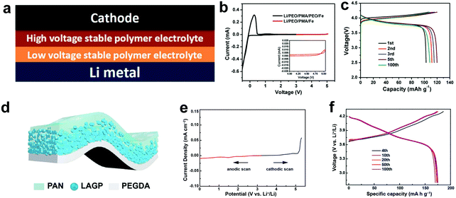 | ||
| Fig. 11 (a) Stacking model of the PMA–PEO bilayer electrolyte. (b) CV curve of a Li/PEO/PMA/Fe (stainless steel) battery (red line) and a Li/PEO/PMA/PEO/Fe battery (black line) from 2.5 to 5.05 V at 65 °C. (c) Voltage profiles of the Li/PEO/PMA/LCO ASSLB at 65 °C and 0.2C. Reproduced with permission.148 Copyright 2018, WILEY-VCH Verlag GmbH & Co. KGaA. (d) Schematic diagram of the HMSE. (e) Electrochemical window of the HMSE. (f) Voltage profiles of the Li/HMSE/NMC811 ASSLB at 0.5C. Reproduced with permission.83 Copyright 2019, WILEY-VCH Verlag GmbH & Co. KGaA. | ||
High voltage ASSLBs with high operating voltage and electrode density are promising to reach the target energy density of 500 W h kg−1 and 1000 W h L−1 at the cell level (see Section 3 for simulations). ISEs generally possess sufficient electrochemical oxidation stability and can be paired with high-voltage cathodes. SPEs with a narrower electrochemical window cannot simultaneously ensure stable anode and cathode (>4 V vs. Li/Li+) interphases. Cross-linking or introducing electrolyte additives proves effective in enhancing the oxidation stability of PEO-based SPEs. Multilayer asymmetric design that can render stable cathode and anode interphases as well as remarkable ionic conductivity is considered an attractive direction for constructing thin SSEs in high-voltage ASSLBs. It is worth noting that although many studies reported approaching 5 V oxidation stability of SSEs by CV or LSV scans, during full cell testing, a lower voltage cut-off of 4.2–4.3 V was applied, mainly due to electrolyte decomposition and interphase instability at higher voltages. Further extending the voltage window of SSEs for larger capacities is beneficial for improving the energy density of the cathode.
5.2 High-capacity lithium–sulfur batteries
The low cost, non-toxic, and naturally abundant sulfur cathode with a high specific capacity of 1675 mA h g−1 endows Li–S batteries with a superior theoretical energy density of 2600 W h kg−1.150–152 However, the soluble polysulfide shuttle between electrodes causes severe problems such as poor sulfur utilization and unsatisfactory cycle life.153–155 Compared to liquid electrolytes, SSEs are believed to suppress the shuttle effect due to the slower dissolution and diffusion of polysulfides in the solid-state.156,157 DeGott first developed all-solid-state Li–S batteries (ASSLSBs) using a PEO electrolyte in 1986, and then the research on SPEs for ASSLSBs mainly focused on PEO-based electrolytes.158 However, the low ionic conductivity of PEO-based electrolytes at RT further slows down the sluggish sulfur chemistry and leads to lower sulfur utilization and poorer cycling performance compared to the liquid electrolyte counterpart. Elevating the temperature above the melting point (65 °C) promotes the ionic conductivity of PEO-based SPEs but at the expense of exacerbating the polysulfide shuttle in the semi-molten polymer. Therefore, enabling RT or near RT operation of PEO-based ASSLSBs is considered as a promising direction. The RT ionic conductivity of PEO-based SPEs is generally boosted by introducing various fillers. Tao et al. added LLZO powders to PEO solution and then cast the dispersion on the sulfur cathode to fabricate a 20–70 μm thick CPE.84 The CPE exhibits an ionic conductivity of 9.5 × 10⁻⁶ and 1.1 × 10⁻⁴ S cm−1 at 20 and 40 °C, respectively, and the ASSLSB delivered a specific capacity of more than 900 mA h g−1 at 37 °C. Sheng et al. prepared a PEO-based electrolyte (20–30 μm) containing ionic liquid grafted oxide nanoparticles (IL@NP) with a high ionic conductivity of 2.32 × 10⁻⁴ S cm−1 at 37 °C.69 The reduced crystallinity of the polymer electrolyte and the weakened interaction between Li+ and PEO contribute to the enhancement in the ionic conductivity. The ASSLSB delivers a reversible specific capacity of ∼600 mA h g−1 at 37 °C. Zhu et al. designed a bilayer structure by infiltrating PEO/LLZO electrolyte on the surface and in the pores of a carbon nanotube/sulfur cathode membrane.134 The integrated framework of the SSE and cathode reduces the interfacial resistance and provides continuous Li+ pathways. ASSLSBs with a 15 μm thick SSE deliver a steady specific capacity of 415 mA h g−1 at RT.Compared with polymer-based electrolytes, ISEs with high RT ionic conductivity and the ability to physically block the polysulfide shuttle have flourishing prospects in Li–S batteries. Among them, sulfides that are relatively soft and have similar chemical components to sulfur or sulfur-based cathode materials are the most promising SSEs for ASSLSBs with good interfacial contact. A Li2S–P2S5 glass-type electrolyte was reported by Scrosati et al. and a high capacity of 1600 mA h g−1 was achieved at 25 °C.159 Xu et al. prepared a thin (100 μm) Li3PS4 (LPS) solid electrolyte by dropping an LPS suspension on a Kevlar nonwoven, followed by pressing onto a stainless steel supported Li2S cathode.97 The Li/Li2S cell with 2.54 mg cm−2 Li2S exhibits a high reversible discharge capacity of 949.9 mA h g−1 at 0.05C and stable cycling for 100 cycles at 0.2C. A superior cell-level energy density of 370.6 W h kg−1 can be realized using the thin SSE paired with a high Li2S loading cathode of 7.64 mg cm−2. The thick porous layer in bilayer or trilayer garnet type SSEs can also be used to hold sulfur, providing continuous ionic pathways while accommodating volume changes of sulfur during discharge/charge.128,129 The thin and dense SSE layer suppresses the polysulfide shuttle and allows fast ion transport.
The polysulfide shuttle effect can be reduced to some degree in SPEs and CPEs due to lower dissolution and diffusion of polysulfides in the polymer matrix. However, the capacity and rate performance at RT or near-RT are still poor because of the slow Li+ transport and large interfacial resistance. Integrating the S cathode with SSEs can lower the interfacial resistance and provide an opportunity to form thin SSEs, which shows great potential for fabrication of ASSLBs with enhanced performance. Additionally, similar to that in high-voltage ASSLBs, bilayer or asymmetric design of SSEs integrating different functions should be explored to tackle the challenges of the polysulfide shuttle, ionic conductivity and mechanical strength. Sulfide ISEs with no polysulfides generated in the charge/discharge process are considered the most promising type of SSEs for ASSLSBs. Thin membranes can be made by infiltrating ductile sulfides into the polymer scaffold. However, the chemical and electrochemical instability remain a major challenge for their practical application. Oxides with dense structure show remarkable performance in suppressing the polysulfide shuttle, but the large interfacial resistance with the electrodes needs to be addressed. Thin SSE design is particularly important for heavy oxides to develop high-energy-density ASSLSBs. Thin oxides with thick electrodes produced by a cost-effective and scalable process are the goal.
5.3 Bipolar solid-state batteries
In contrast to the conventional LIBs, where liquid electrolytes immerse all components, the confined SSE enables the implementation of bipolar stacking, where mono cells are alternately stacked in a single package without an external electrical connection.15,160 The bipolar design allows for building up of the total output voltage and reducing the packaging materials, which leads to the improvement of the energy density and reduction of the manufacturing cost for large-scale battery systems (Fig. 12a).17 The stacking strategies for bipolar design are generally classified into 2 categories, the lamination of free-standing SSEs and the layer-by-layer coating of SSEs on the electrode.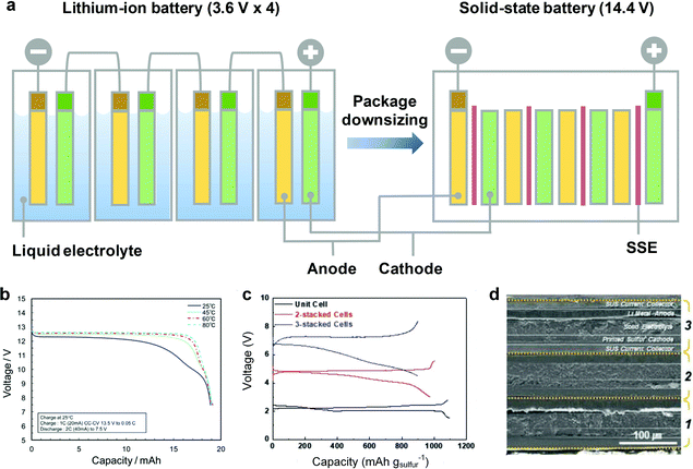 | ||
| Fig. 12 (a) Comparison at the pack level of conventional liquid LIBs and ASSLBs. (b) Discharge curves of the 12 V bipolar cell at various temperatures. Reproduced with permission.135 Copyright 2016 Elsevier. (c) CV curves of the bipolar cells at the 1st cycle at 0.1C. (d) SEM image of the bipolar cell with 3-stacked mono cells. Reproduced with permission.162 Copyright 2019, WILEY-VCH Verlag GmbH & Co. KGaA. | ||
Nam et al. synthesized a freestanding sulfide SSE reinforced by a PPTA scaffold via a cold-press “transfer” process, and the thin (70 μm) and flexible SSE enables facile stacking of mono-cells.98 The voltage of the bipolar LTO/LCO cell consisting of two mono-cells is doubled and exhibits a plateau at 4.5 V. Shin et al. reported a free-standing and flexible biphasic solid electrolyte (30 μm thick) composed of perovskite-type Li0.29La0.57TiO3 (LLTO) and PEO by a tape casting method.161 The Li/NMC bipolar cell based on 3 mono-cells is successfully operated in a voltage range of 9.2–12.0 V, demonstrating successful stacking without short circuit or current leakage. The bipolar cell delivers a specific capacity of 125 mA h g−1 with a capacity retention of 83% after 50 cycles.
Layer-by-layer coating of electrode and SSE slurries on a current collector is simple and scalable. Yoshima et al. demonstrated a 12 V-class bipolar battery composed of a thin SSE (3 μm) of Li7La3Zr2O12 (LLZ) particles coated with 4 wt% PAN-based gel polymer electrolyte.135 LiMn0.8Fe0.2PO4 (LMFP, cathodes) and LTO (anodes) are slurry coated on the opposite sides of an Al current collector, and then the SSE slurry was coated on both sides of the bipolar electrode, arranged in a face-to-face configuration, before the heating polymerization process. The 12 V pouch cell (20 mA h) constructed by stacking 5 bipolar electrodes shows stable cycling at 60 °C (85% capacity retention after 200 cycles), good rate capacity from 0.2 to 20C at 25 °C, and sufficient capacity retention at −40 °C (50% capacity retention of that at 25 °C), demonstrating successful operation in a wide temperature range (Fig. 12b). Recently, Kim et al. reported a bipolar ASSLSB based on two thermodynamically immiscible gel electrolytes of ethyl methyl sulfone (EMS) and tetraethylene glycol dimethyl ether (TEGDME).162 The EMS gel electrolyte embedded in the sulfur cathode shows the dual-functionality of a binder and sulfur utilization promoter, whereas the TEGDME composite gel electrolyte functions as a polysulfide-repelling separator membrane (∼50 μm). Bipolar cells were connected by a UV curing-assisted stepwise printing process, showing good electrolyte/electrode interfacial contact (Fig. 12d). The open-circuit voltage of the bipolar cell is proportional to the number of mono-cells, which is 5.6 V for a 2-stacked cell and 8.4 V for a 3-stacked cell (Fig. 12c). Bipolar cells with 2-stacked and 3-stacked mono-cells deliver initial discharge capacities of ∼1000 mA h g−1 and ∼900 mA h g−1, respectively. The bipolar cells also show exceptional advances in mechanical foldability and safety, which is promising in realization of scalable fabrication of high-energy-density ASSLBs.
5.4 Flexible solid-state batteries
With the rapid development of flexible electronics, flexible batteries have attracted increasing attention as power sources for flexible and wearable devices.163,164 SPEs and CPEs are preferable for flexible ASSLBs due to their flexibility and the facile lamination processing. SSEs with scaffold support usually show great bending-tolerance, and are successfully applied in flexible ASSLBs. A 25 μm-thick SPE composed of in situ cross-linked ETPTA on a PET nonwoven in the presence of plastic crystal SN shows strong resistance against mechanical deformations, which enables a stable electrochemical performance even in a severely wrinkled state.18 PEO-based CPEs supported by porous scaffolds such as PI and PE all show great flexibility and high tolerance to mechanical abuse, and demonstrate steady performance in flexible pouch cells under deformation.20,90,106,117 With deliberate design, ISEs supported by a flexible polymer matrix can also exhibit sufficient bendability to enable flexible ASSLBs. A 100 μm bendable ISE was obtained by pressing LLZTO interconnected by a fibrous PTFE binder into nylon mesh.117 The Li/NMC532 pouch cell using this flexible ISE can light up a diode array even under harsh conditions such as bending and cutting. Flexible Li6PS5Cl0.5Br0.5 infiltrated PI (PI-LPSClBr) was prepared by dropping sulfide solution onto electrospun PI fibers followed by heat treatment.118 The thin (40–70 μm) PI-LPSClBr film shows great flexibility and can wrap around a 3 cm-diameter rod. Hence, the development of ultrathin SSEs can also extend the application in flexible ASSLBs.6. Summary and perspectives
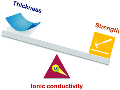
The replacement of liquid electrolytes with SSEs makes LMBs promising for next-generation energy storage systems. The thickness of the SSE membrane needs to be reduced below 25 μm to potentially realize high gravimetric/volumetric densities of 500 W h kg−1/1000 W h L−1. However, the reported thicknesses of SPEs and CPEs are generally in the range of 80–200 μm, and the dense ISE pallets prepared by the widely used powder pressing method are up to 1 mm thick. Those thick SSEs inevitably offset the advantages of high-energy electrodes by the excessively large amount of inactive components. Therefore, more attention has been paid to reducing the thickness of SSEs in recent years. The thickness, together with the ionic conductivity and mechanical strength, of SSEs proves crucial in meeting the criteria of high-performance and safe ASSLBs (Fig. 13). High ionic conductivity is the essential prerequisite of a functional SSE. Reducing the electrolyte thickness facilitates ion transport and improves the performance of the resultant ASSLBs. Meanwhile, the mechanical reliability of SSEs is a key aspect related to safety. Thin SSEs must have sufficient strength to resist fracture or Li dendrite penetration over long-term cycling. Employing robust scaffolds and developing advanced casting techniques are two main strategies to balance the minimized thickness against reliable mechanical properties.Fig. 14 shows the variety of scaffold-support SSEs. Great efforts have been dedicated to reducing the thickness of SSEs with enhanced mechanical strength by introducing flexible and robust polymer scaffolds. The facile infiltration process can produce thin SSEs below 10 μm. However, polymer scaffolds are usually poor ion conductors, and Li+ can only diffuse in the impregnated electrolyte region, which leads to the inevitable reduction of the ionic conductivity. High porosity and interconnected pores of the scaffold are crucial in facilitating ion conduction in the SSE. Vertically aligned pores provide low-tortuosity ion diffusion, but the fabrication of polymers with vertically aligned channels is usually costly, and the porosity falls behind compared to scaffolds with randomly distributed pores. Future development of polymer scaffolds needs to focus on pore structure engineering and creating cost-effective polymers with abundant vertically aligned ion channels. Biomass with well-aligned channel structure may be a promising candidate as electrolyte supports due to its low cost and natural abundance.
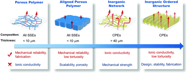 | ||
| Fig. 14 Illustration of the applicable electrolytes, minimum thicknesses, and advantages and challenges of various scaffold supported SSEs. | ||
Inorganic scaffolds can function as interconnected filler networks of polymer electrolytes to increase the ion conduction either by reducing the polymer crystallinity or by directly participating in ion transport. However, an inorganic network is not as robust as a polymer scaffold, and thereby the resultant SSEs are usually thicker (>40 μm). For greater robustness and flexibility, a large aspect ratio and highly entangled structure are necessary. Furthermore, minimizing the thickness of the inorganic network with ordered structure for optimized ion transport is worth future exploration.
The scalable and industry-compatible tape casting technique is considered an attractive direction for commercialization of thin SSEs. The thickness of the electrolyte layer is controlled by the slurry composition and scraper height. Fig. 15 illustrates the advantages and challenges of thin SSEs produced by various tape casting methods. With the help of the cathode layer to provide mechanical support, SSEs even thinner than 5 μm can be obtained with good interfacial contact. During fabrication, careful consideration must be taken in choosing the solvents and binders of the cathode and the SSE slurries to avoid layer mixing-up or dissolution of the cathode layer when applying the SSE slurry. Tape casting an oxide SSE slurry on a release film allows the following high-temperature sintering (usually >800 °C) to achieve improved crystallinity and higher ionic conductivity. However, combustion of polymer binders makes the freestanding membrane brittle, resulting in processing difficulties. A balance between the ionic conductivity and processability of thin oxide membranes should be considered. Laminating thick porous and thin dense layers provides an opportunity to fabricate defect-free oxide SSEs thinner than 20 μm. The thick porous layer ensures mechanical strength and high electrode material loading. Although tape casting enables scalable production of layered ISEs, the electrode materials must be infiltrated into the porous layer, which requires a multistep fabrication process. Strategies to simplify the cell fabrication process are necessary. Continuous processes that are adoptable in current LIB fabrication, such as the roll-to-roll process, are the ultimate goal for commercially-viable production of ASSLBs.
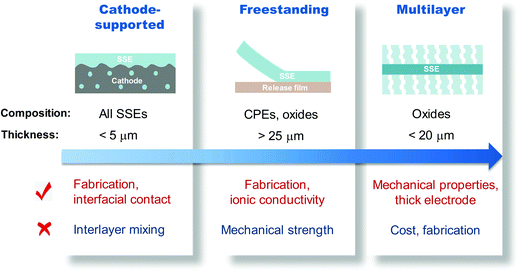 | ||
| Fig. 15 Illustration of the applicable electrolytes, minimum thicknesses, and advantages and challenges of various tape cast SSEs. | ||
The environmental sensitivity of different electrolyte systems is an important factor influencing the manufacture, performance, cost and safety of solid-state batteries. Sulfides exhibit the highest ionic conductivity among all SSEs, approaching that of liquid electrolytes. However, sulfides and their precursors are extremely sensitive to moisture and produce toxic H2S gas. Therefore, sulfide SSEs must be handled under an inert atmosphere, which is a main drawback in practical applications. Ductile sulfides can be pressed into porous scaffolds, solution cast on top of the cathode film, or hot pressed into thin films. Oxides are generally considered stable in the atmosphere, although garnet-type oxides do react with H2O and CO2 in air and form LiOH and Li2CO3 on the surface. Thin oxide films can be fabricated by infiltrating into a porous polymer network, and solution casting onto a cathode or release film. Multilayer designs that integrate the dense electrolyte layer and the porous supporting layer are advantageous in producing ultrathin oxide SSEs. Polymers are generally stable in air but the dissolved salts easily adsorb H2O, so the preparation of SPEs is usually carried out in a dry-room or Ar-filled glovebox. The most effective strategy to produce thin SPEs is to support them by robust polymer or inorganic networks. The mechanical strength of SPEs is too weak to be cast into free-standing thin films without the risk of short-circuiting during cycling. Incorporating inorganic fillers into the polymer matrix improves the mechanical properties of the resulting CPEs and provides opportunities for thinning films by tape casting.
For thin SPEs, the design should still focus on enhancing the ionic conductivity to allow steady operation at RT, increasing the mechanical strength to suppress Li dendrites, and broadening the electrochemical window to pair with high-voltage cathodes. Composite or asymmetric systems seem a promising direction to achieve the goals, and exploration of new polymer or salt design is also very important. For ISEs, the interfacial instability between the electrolyte and Li metal anode remains a critical problem affecting the performance of ASSLBs. As ISE membranes get thinner, such problems are becoming more critical, since thinner ISEs would be penetrated more easily by the interfacial side-reactions and dendrite growth. Tremendous efforts have been made to address the interface issue by coating ISEs with various interlayer materials. However, operation on thin ISEs is challenging due to the reduced mechanical properties. One promising approach is to construct Li composites or Li alloys by introducing a second phase to guarantee close contact between the Li anode and thin ISE and to suppress Li dendrite growth.58,165–168
Fabrication convenience and cost are critical parameters for the scale-up from lab research to industrial mass production. From this perspective, oxides that need high-energy ball-milling and high temperature/pressure post-sintering or sulfides that require a stringent inert atmosphere seem to be difficult to be implemented industrially. Solution-based fabrication followed by a roll-to-roll process is more promising for the short-term application of high energy-density ASSLBs. Synthesizing thin SSEs using commercially available materials or biomass is also rewarding. At the same time, more efforts need to be put into bipolar designs and flexible batteries to enable large-scale energy storage systems. It also should be noted that the majority of thin SSEs are tested in coin-cell geometries. Therefore, although extensive academic research has been carried out, there is still a big gap between lab-scale scientific findings and industrial-level applications. Testing thin solid-state electrolytes in large pouch-cell settings close to commercial implementation is necessary to obtain realistic assessments of electrochemical performances and energy densities.
There is no doubt that SSEs will play an important role in the development of safe and high-energy-density Li metal batteries. The design and development of thin and robust SSE membranes have received growing academic and industrial interest, and more breakthroughs are expected in the near future.
Conflicts of interest
There are no conflicts to declare.Acknowledgements
The authors thank the financial supports of the National Key R&D Program of China (2016YFB0100302), Natural Science Foundation of China (No. 51972131, 51632001 and 52002138) and China Postdoctoral Science Foundation (2019M662613).References
- D. Larcher and J. M. Tarascon, Nat. Chem., 2015, 7, 19–29 CrossRef CAS.
- M. Li, J. Lu, Z. Chen and K. Amine, Adv. Mater., 2018, 30, 1800561 CrossRef.
- A. Manthiram, X. W. Yu and S. F. Wang, Nat. Rev. Mater., 2017, 2, 16103 CrossRef CAS.
- J. Duan, X. Tang, H. Dai, Y. Yang, W. Wu, X. Wei and Y. Huang, Electrochem. Energy Rev., 2019, 3, 1–42 Search PubMed.
- J. Wu, L. Yuan, Z. Li, X. Xie and Y. Huang, Mater. Horiz., 2020, 7, 2619–2634 RSC.
- J. Wu, X. Li, Z. Rao, X. Xu, Z. Cheng, Y. Liao, L. Yuan, X. Xie, Z. Li and Y. Huang, Nano Energy, 2020, 72, 104725 CrossRef CAS.
- J. Duan, Y. Zheng, W. Luo, W. Wu, T. Wang, Y. Xie, S. Li, J. Li and Y. Huang, Natl. Sci. Rev., 2020, 7, 1208–1217 CrossRef.
- P. Albertus, S. Babinec, S. Litzelman and A. Newman, Nat. Energy, 2018, 3, 16–21 CrossRef CAS.
- J. Xiang, L. Yang, L. Yuan, K. Yuan, Y. Zhang, Y. Huang, J. Lin, F. Pan and Y. Huang, Joule, 2019, 3, 2334–2363 CrossRef CAS.
- X. Zheng, Z. Gu, X. Liu, Z. Wang, J. Wen, X. Wu, W. Luo and Y. Huang, Energy Environ. Sci., 2020, 13, 1788–1798 RSC.
- C. Chen, D. Liu and X. Xiong, Acta Phys.-Chim. Sin., 2020, 202008078, DOI:10.3866/pku.whxb202008078.
- J. Wu, H. Zeng, Q. Shi, X. Li, Q. Xia, Z. Xue, Y. Ye and X. Xie, J. Power Sources, 2018, 405, 7–17 CrossRef CAS.
- S.-J. Tan, X.-X. Zeng, Q. Ma, X.-W. Wu and Y.-G. Guo, Electrochem. Energy Rev., 2018, 1, 113–138 CrossRef CAS.
- H. T. Xu, H. R. Zhang, J. Ma, G. J. Xu, T. T. Dong, J. C. Chen and G. L. Cui, ACS Energy Lett., 2019, 4, 2871–2886 CrossRef CAS.
- K. N. Jung, H. S. Shin, M. S. Park and J. W. Lee, ChemElectroChem, 2019, 6, 3842–3859 CrossRef CAS.
- D. Zhou, D. Shanmukaraj, A. Tkacheva, M. Armand and G. Wang, Chem, 2019, 5, 2326–2352 CAS.
- J. Schnell, T. Günther, T. Knoche, C. Vieider, L. Köhler, A. Just, M. Keller, S. Passerini and G. Reinhart, J. Power Sources, 2018, 382, 160–175 CrossRef CAS.
- K.-H. Choi, S.-J. Cho, S.-H. Kim, Y. H. Kwon, J. Y. Kim and S.-Y. Lee, Adv. Funct. Mater., 2014, 24, 44–52 CrossRef CAS.
- D. Zhou, Y.-B. He, R. Liu, M. Liu, H. Du, B. Li, Q. Cai, Q.-H. Yang and F. Kang, Adv. Energy Mater., 2015, 5, 1500353 CrossRef.
- J. Wan, J. Xie, X. Kong, Z. Liu, K. Liu, F. Shi, A. Pei, H. Chen, W. Chen, J. Chen, X. Zhang, L. Zong, J. Wang, L. Q. Chen, J. Qin and Y. Cui, Nat. Nanotechnol., 2019, 14, 705–711 CrossRef CAS.
- M. Ue, K. Sakaushi and K. Uosaki, Mater. Horiz., 2020, 7, 1937–1954 RSC.
- J. Wan, J. Xie, D. G. Mackanic, W. Burke, Z. Bao and Y. Cui, Mater. Today Nano, 2018, 4, 1–16 CrossRef.
- R. Chen, W. Qu, X. Guo, L. Li and F. Wu, Mater. Horiz., 2016, 3, 487–516 RSC.
- Z. Gao, H. Sun, L. Fu, F. Ye, Y. Zhang, W. Luo and Y. Huang, Adv. Mater., 2018, 30, 1705702 CrossRef.
- S. Li, S. Q. Zhang, L. Shen, Q. Liu, J. B. Ma, W. Lv, Y. B. He and Q. H. Yang, Adv. Sci., 2020, 7, 1903088 CrossRef CAS.
- G. S. MacGlashan, Y. G. Andreev and P. G. Bruce, Nature, 1999, 398, 792–794 CrossRef CAS.
- Q. Wang, W.-L. Song, L.-Z. Fan and Y. Song, J. Membr. Sci., 2015, 486, 21–28 CrossRef CAS.
- X. Zhang, S. Wang, C. Xue, C. Xin, Y. Lin, Y. Shen, L. Li and C. W. Nan, Adv. Mater., 2019, 31, e1806082 CrossRef.
- J. Zhang, J. Zhao, L. Yue, Q. Wang, J. Chai, Z. Liu, X. Zhou, H. Li, Y. Guo, G. Cui and L. Chen, Adv. Energy Mater., 2015, 5, 1501082 CrossRef.
- H.-W. Chen, T.-P. Lin and F.-C. Chang, Polymer, 2002, 43, 5281–5288 CrossRef CAS.
- L. Yue, J. Ma, J. Zhang, J. Zhao, S. Dong, Z. Liu, G. Cui and L. Chen, Energy Storage Mater., 2016, 5, 139–164 CrossRef.
- Z. Xue, D. He and X. Xie, J. Mater. Chem. A, 2015, 3, 19218–19253 RSC.
- P. P. Soo, B. Huang, Y.-I. Jang, Y.-M. Chiang, D. R. Sadoway and A. M. Mayes, J. Electrochem. Soc., 1999, 146, 32–37 CrossRef CAS.
- D. R. Sadoway, J. Power Sources, 2004, 129, 1–3 CrossRef CAS.
- H. Zhang, X. Judez, A. Santiago, M. Martinez-Ibañez, M. Á. Muñoz-Márquez, J. Carrasco, C. Li, G. G. Eshetu and M. Armand, Adv. Energy Mater., 2019, 9, 1900763 CrossRef.
- G. G. Eshetu, X. Judez, C. Li, O. Bondarchuk, L. M. Rodriguez-Martinez, H. Zhang and M. Armand, Angew. Chem., Int. Ed., 2017, 56, 15368–15372 CrossRef CAS.
- L. Z. Fan, Y. S. Hu, A. J. Bhattacharyya and J. Maier, Adv. Funct. Mater., 2007, 17, 2800–2807 CrossRef CAS.
- M. Forsyth, L. Porcarelli, X. Wang, N. Goujon and D. Mecerreyes, Acc. Chem. Res., 2019, 52, 686–694 CrossRef CAS.
- C. Z. Zhao, X. Q. Zhang, X. B. Cheng, R. Zhang, R. Xu, P. Y. Chen, H. J. Peng, J. Q. Huang and Q. Zhang, Proc. Natl. Acad. Sci. U. S. A., 2017, 114, 11069–11074 CrossRef CAS.
- L. Chen, Y. Li, S.-P. Li, L.-Z. Fan, C.-W. Nan and J. B. Goodenough, Nano Energy, 2018, 46, 176–184 CrossRef CAS.
- P. J. Alarco, Y. Abu-Lebdeh, A. Abouimrane and M. Armand, Nat. Mater., 2004, 3, 476–481 CrossRef CAS.
- M. Echeverri, N. Kim and T. Kyu, Macromolecules, 2012, 45, 6068–6077 CrossRef CAS.
- C. Wang, K. R. Adair, J. Liang, X. Li, Y. Sun, X. Li, J. Wang, Q. Sun, F. Zhao, X. Lin, R. Li, H. Huang, L. Zhang, R. Yang, S. Lu and X. Sun, Adv. Funct. Mater., 2019, 1900392 CrossRef.
- H. Zhang, C. Li, M. Piszcz, E. Coya, T. Rojo, L. M. Rodriguez-Martinez, M. Armand and Z. Zhou, Chem. Soc. Rev., 2017, 46, 797–815 RSC.
- R. Bouchet1, S. Maria, R. Meziane, A. Aboulaich, L. Lienafa, J.-P. Bonnet, T. N. T. Phan, D. Bertin, D. Gigmes, D. Devaux, R. Denoye and M. Armand, Nat. Mater., 2013, 12, 452–457 CrossRef.
- N. Lago, O. Garcia-Calvo, J. M. Lopez del Amo, T. Rojo and M. Armand, ChemSusChem, 2015, 8, 3039–3043 CrossRef CAS.
- A. Blazejczyk, M. Szczupak, W. Wieczorek, P. Cmoch, G. B. Appetecchi, B. Scrosati, R. Kovarsky, D. Golodnitsky and E. Peled, Chem. Mater., 2005, 17, 1535–1547 CrossRef CAS.
- T. Famprikis, P. Canepa, J. A. Dawson, M. S. Islam and C. Masquelier, Nat. Mater., 2019, 18, 1278–1291 CrossRef CAS.
- C. R. Mariappan, C. Yada, F. Rosciano and B. Roling, J. Power Sources, 2011, 196, 6456–6464 CrossRef CAS.
- H. Aono, E. Sugimoto, Y. Sadaoka, N. Imanaka and G.-Y. Adachi, Solid State Ionics, 1990, 40–41, 38–42 CrossRef CAS.
- H. Morimoto, H. Awano, J. Terashima, Y. Shindo, S. Nakanishi, N. Ito, K. Ishikawa and S.-I. Tobishima, J. Power Sources, 2013, 240, 636–643 CrossRef CAS.
- J. K. Feng, L. Lu and M. O. Lai, J. Alloys Compd., 2010, 501, 255–258 CrossRef CAS.
- O. Bohnke, Solid State Ionics, 2008, 179, 9–15 CrossRef CAS.
- S. Stramare, V. Thangadurai and W. Weppner, Chem. Mater., 2003, 15, 3974–3990 CrossRef CAS.
- S. Wenzel, T. Leichtweiss, D. Krüger, J. Sann and J. Janek, Solid State Ionics, 2015, 278, 98–105 CrossRef CAS.
- V. Thangadurai, S. Narayanan and D. Pinzaru, Chem. Soc. Rev., 2014, 43, 4714–4727 RSC.
- J. Awaka, N. Kijima, H. Hayakawa and J. Akimoto, J. Solid State Chem., 2009, 182, 2046–2052 CrossRef CAS.
- J. Wen, Y. Huang, J. Duan, Y. Wu, W. Luo, L. Zhou, C. Hu, L. Huang, X. Zheng, W. Yang, Z. Wen and Y. Huang, ACS Nano, 2019, 13, 14549–14556 CrossRef CAS.
- J. Duan, L. Huang, T. Wang, Y. Huang, H. Fu, W. Wu, W. Luo and Y. Huang, Adv. Funct. Mater., 2020, 30, 1908701 CrossRef CAS.
- J. H. Kennedy, S. Sahami, S. W. Shea and Z. Zhang, Solid State Ionics, 1986, 18–19, 368–371 CrossRef CAS.
- A. Hayashi, S. Hama, T. Minami and M. Tatsumisago, Electrochem. Commun., 2003, 5, 111–114 CrossRef CAS.
- N. Kamaya, K. Homma, Y. Yamakawa, M. Hirayama, R. Kanno, M. Yonemura, T. Kamiyama, Y. Kato, S. Hama, K. Kawamoto and A. Mitsui, Nat. Mater., 2011, 10, 682–686 CrossRef CAS.
- H. Muramatsu, A. Hayashi, T. Ohtomo, S. Hama and M. Tatsumisago, Solid State Ionics, 2011, 182, 116–119 CrossRef CAS.
- F. Croce, G. B. Appetecchi, L. Persi and B. Scrosati, Nature, 1998, 394, 456–458 CrossRef CAS.
- T. Wang, R. Zhang, Y. Wu, G. Zhu, C. Hu, J. Wen and W. Luo, J. Energy Chem., 2020, 46, 187 CrossRef.
- S. Choudhury, R. Mangal, A. Agrawal and L. A. Archer, Nat. Commun., 2015, 6, 10101 CrossRef CAS.
- Q. Pan, D. M. Smith, H. Qi, S. Wang and C. Y. Li, Adv. Mater., 2015, 27, 5995–6001 CrossRef CAS.
- J. Shim, H. J. Kim, B. G. Kim, Y. S. Kim, D.-G. Kim and J.-C. Lee, Energy Environ. Sci., 2017, 10, 1911–1916 RSC.
- O. Sheng, C. Jin, J. Luo, H. Yuan, C. Fang, H. Huang, Y. Gan, J. Zhang, Y. Xia, C. Liang, W. Zhang and X. Tao, J. Mater. Chem. A, 2017, 5, 12934–12942 RSC.
- H. Xu, P. H. Chien, J. Shi, Y. Li, N. Wu, Y. Liu, Y. Y. Hu and J. B. Goodenough, Proc. Natl. Acad. Sci. U. S. A., 2019, 116, 18815–18821 CrossRef CAS.
- W. Liu, N. Liu, J. Sun, P. C. Hsu, Y. Li, H. W. Lee and Y. Cui, Nano Lett., 2015, 15, 2740–2745 CrossRef CAS.
- J. Gao, Q. Shao and J. Chen, J. Energy Chem., 2020, 46, 237 CrossRef.
- F. Croce, G. B. Appetecchi, L. Persi and B. Scrosati, Nature, 1998, 394, 456–458 CrossRef CAS.
- D. Lin, P. Y. Yuen, Y. Liu, W. Liu, N. Liu, R. H. Dauskardt and Y. Cui, Adv. Mater., 2018, 30, e1802661 CrossRef.
- J. Bae, Y. Li, J. Zhang, X. Zhou, F. Zhao, Y. Shi, J. B. Goodenough and G. Yu, Angew. Chem., Int. Ed., 2018, 57, 2096–2100 CrossRef CAS.
- W. Liu, S. W. Lee, D. Lin, F. Shi, S. Wang, A. D. Sendek and Y. Cui, Nat. Energy, 2017, 2, 17035 CrossRef CAS.
- H. Zhai, P. Xu, M. Ning, Q. Cheng, J. Mandal and Y. Yang, Nano Lett., 2017, 17, 3182–3187 CrossRef CAS.
- X. Zhang, J. Xie, F. Shi, D. Lin, Y. Liu, W. Liu, A. Pei, Y. Gong, H. Wang, K. Liu, Y. Xiang and Y. Cui, Nano Lett., 2018, 18, 3829–3838 CrossRef CAS.
- Y. Lin, X. M. Wang, J. Liu and J. D. Miller, Nano Energy, 2017, 31, 478–485 CrossRef CAS.
- J. Liu, Z. Bao, Y. Cui, E. J. Dufek, J. B. Goodenough, P. Khalifah, Q. Li, B. Y. Liaw, P. Liu, A. Manthiram, Y. S. Meng, V. R. Subramanian, M. F. Toney, V. V. Viswanathan, M. S. Whittingham, J. Xiao, W. Xu, J. Yang, X.-Q. Yang and J.-G. Zhang, Nat. Energy, 2019, 4, 180–186 CrossRef CAS.
- B. Liu, J.-G. Zhang and W. Xu, Joule, 2018, 2, 833–845 CrossRef CAS.
- Z. Zhang, S. Chen, X. Yao, P. Cui, J. Duan, W. Luo, Y. Huang and X. Xu, Energy Storage Mater., 2020, 24, 714–718 CrossRef.
- H. Duan, M. Fan, W. P. Chen, J. Y. Li, P. F. Wang, W. P. Wang, J. L. Shi, Y. X. Yin, L. J. Wan and Y. G. Guo, Adv. Mater., 2019, 31, e1807789 CrossRef.
- X. Tao, Y. Liu, W. Liu, G. Zhou, J. Zhao, D. Lin, C. Zu, O. Sheng, W. Zhang, H. W. Lee and Y. Cui, Nano Lett., 2017, 17, 2967–2972 CrossRef CAS.
- K. Pan, L. Zhang, W. Qian, X. Wu, K. Dong, H. Zhang and S. Zhang, Adv. Mater., 2020, 32, e2000399 CrossRef.
- J. W. Choi and D. Aurbach, Nat. Rev. Mater., 2016, 1, 16013 CrossRef CAS.
- X. Yang, J. Luo and X. Sun, Chem. Soc. Rev., 2020, 49, 2140–2195 RSC.
- Y. J. Nam, D. Y. Oh, S. H. Jung and Y. S. Jung, J. Power Sources, 2018, 375, 93–101 CrossRef CAS.
- Y. Cui, X. Liang, J. Chai, Z. Cui, Q. Wang, W. He, X. Liu, Z. Liu, G. Cui and J. Feng, Adv. Sci., 2017, 4, 1700174 CrossRef.
- J. Wu, Z. Rao, Z. Cheng, L. Yuan, Z. Li and Y. Huang, Adv. Energy Mater., 2019, 9, 1902767 CrossRef CAS.
- Y. Cui, J. Wan, Y. Ye, K. Liu, L. Y. Chou and Y. Cui, Nano Lett., 2020, 20, 1686–1692 CrossRef CAS.
- R. Khurana, J. L. Schaefer, L. A. Archer and G. W. Coates, J. Am. Chem. Soc., 2014, 136, 7395–7402 CrossRef CAS.
- B. Zhang, Y. Zhang, N. Zhang, J. Liu, L. Cong, J. Liu, L. Sun, A. Mauger, C. M. Julien, H. Xie and X. Pan, J. Power Sources, 2019, 428, 93–104 CrossRef CAS.
- X. Yang, Q. Sun, C. Zhao, X. Gao, K. R. Adair, Y. Liu, J. Luo, X. Lin, J. Liang, H. Huang, L. Zhang, R. Yang, S. Lu, R. Li and X. Sun, Nano Energy, 2019, 61, 567–575 CrossRef CAS.
- P. Walke, K. M. Freitag, H. Kirchhain, M. Kaiser, L. van Wüllen and T. Nilges, Z. Anorg. Allg. Chem., 2018, 644, 1863–1874 CrossRef CAS.
- H. Wang, Q. Wang, X. Cao, Y. He, K. Wu, J. Yang, H. Zhou, W. Liu and X. Sun, Adv. Mater., 2020, 32, e2001259 CrossRef.
- R. Xu, J. Yue, S. Liu, J. Tu, F. Han, P. Liu and C. Wang, ACS Energy Lett., 2019, 4, 1073–1079 CrossRef CAS.
- Y. J. Nam, S. J. Cho, D. Y. Oh, J. M. Lim, S. Y. Kim, J. H. Song, Y. G. Lee, S. Y. Lee and Y. S. Jung, Nano Lett., 2015, 15, 3317–3323 CrossRef CAS.
- M. Yamamoto, Y. Terauchi, A. Sakuda and M. Takahashi, Sci. Rep., 2018, 8, 1212 CrossRef.
- Z. Jiang, S. Wang, X. Chen, W. Yang, X. Yao, X. Hu, Q. Han and H. Wang, Adv. Mater., 2020, 32, 1906221 CrossRef CAS.
- X. B. Zhu, T. S. Zhao, Z. H. Wei, P. Tan and G. Zhao, Energy Environ. Sci., 2015, 8, 2782–2790 RSC.
- X. G. Hao, Q. Zhao, S. M. Su, S. Q. Zhang, J. B. Ma, L. Shen, Q. P. Yu, L. Zhao, Y. Liu, F. Y. Kang and Y. B. He, Adv. Energy Mater., 2019, 9, 1901604 CrossRef.
- S. Yu, A. Mertens, H. Tempel, R. Schierholz, H. Kungl and R.-A. Eichel, ACS Appl. Mater. Interfaces, 2018, 10, 22264–22277 CrossRef CAS.
- M. Finsterbusch, T. Danner, C.-L. Tsai, S. Uhlenbruck, A. Latz and O. Guillon, ACS Appl. Mater. Interfaces, 2018, 10, 22329–22339 CrossRef CAS.
- D. Xie, S. Chen, Z. Zhang, J. Ren, L. Yao, L. Wu, X. Yao and X. Xu, J. Power Sources, 2018, 389, 140–147 CrossRef CAS.
- J. Hu, P. He, B. Zhang, B. Wang and L.-Z. Fan, Energy Storage Mater., 2020, 26, 283–289 CrossRef.
- H. Duan, Y. X. Yin, Y. Shi, P. F. Wang, X. D. Zhang, C. P. Yang, J. L. Shi, R. Wen, Y. G. Guo and L. J. Wan, J. Am. Chem. Soc., 2018, 140, 82–85 CrossRef CAS.
- X. Chen, W. He, L.-X. Ding, S. Wang and H. Wang, Energy Environ. Sci., 2019, 12, 938–944 RSC.
- T.-J. Cai, Y.-H. Lo and J.-J. Wu, Mater. Today Energy, 2019, 13, 119–124 CrossRef.
- K. K. Fu, Y. Gong, J. Dai, A. Gong, X. Han, Y. Yao, C. Wang, Y. Wang, Y. Chen, C. Yan, Y. Li, E. D. Wachsman and L. Hu, Proc. Natl. Acad. Sci. U. S. A., 2016, 113, 7094–7099 CrossRef CAS.
- Z. Wan, D. Lei, W. Yang, C. Liu, K. Shi, X. Hao, L. Shen, W. Lv, B. Li, Q.-H. Yang, F. Kang and Y.-B. He, Adv. Funct. Mater., 2019, 29, 1805301 CrossRef.
- H. Xie, C. Yang, K. K. Fu, Y. Yao, F. Jiang, E. Hitz, B. Liu, S. Wang and L. Hu, Adv. Energy Mater., 2018, 8, 1703474 CrossRef.
- P. Zhu, C. Yan, M. Dirican, J. Zhu, J. Zang, R. K. Selvan, C.-C. Chung, H. Jia, Y. Li, Y. Kiyak, N. Wu and X. Zhang, J. Mater. Chem. A, 2018, 6, 4279–4285 RSC.
- X. Wang, H. Zhai, B. Qie, Q. Cheng, A. Li, J. Borovilas, B. Xu, C. Shi, T. Jin, X. Liao, Y. Li, X. He, S. Du, Y. Fu, M. Dontigny, K. Zaghib and Y. Yang, Nano Energy, 2019, 60, 205–212 CrossRef CAS.
- Y. Zhao, C. Wu, G. Peng, X. Chen, X. Yao, Y. Bai, F. Wu, S. Chen and X. Xu, J. Power Sources, 2016, 301, 47–53 CrossRef CAS.
- D. Lin, W. Liu, Y. Liu, H. R. Lee, P. C. Hsu, K. Liu and Y. Cui, Nano Lett., 2016, 16, 459–465 CrossRef CAS.
- T. Jiang, P. He, G. Wang, Y. Shen, C. W. Nan and L. Z. Fan, Adv. Energy Mater., 2020, 10, 1903376 CrossRef CAS.
- D. H. Kim, Y. H. Lee, Y. B. Song, H. Kwak, S. Y. Lee and Y. S. Jung, ACS Energy Lett., 2020, 5, 718–727 CrossRef CAS.
- X. Ma, X. Zuo, J. Wu, X. Deng, X. Xiao, J. Liu and J. Nan, J. Mater. Chem. A, 2018, 6, 1496–1503 RSC.
- C. Wang, T. Wang, L. Wang, Z. Hu, Z. Cui, J. Li, S. Dong, X. Zhou and G. Cui, Adv. Sci., 2019, 6, 1901036 CrossRef CAS.
- Y. Li, X. Wang, H. Zhou, X. Xing, A. Banerjee, J. Holoubek, H. Liu, Y. S. Meng and P. Liu, ACS Energy Lett., 2020, 5, 955–961 CrossRef CAS.
- B. Timurkutluk and S. Dokuyucu, Ceram. Int., 2018, 44, 17399–17406 CrossRef CAS.
- X. Chen, W. Ni, X. Du, Z. Sun, T. Zhu, Q. Zhong and M. Han, J. Mater. Sci. Technol., 2019, 35, 695–701 CrossRef.
- D. H. S. Tan, A. Banerjee, Z. Chen and Y. S. Meng, Nat. Nanotechnol., 2020, 15, 170–180 CrossRef CAS.
- A. Li, X. Liao, H. Zhang, L. Shi, P. Wang, Q. Cheng, J. Borovilas, Z. Li, W. Huang, Z. Fu, M. Dontigny, K. Zaghib, K. Myers, X. Chuan, X. Chen and Y. Yang, Adv. Mater., 2020, 32, e1905517 CrossRef.
- R. K. Nishihora, P. L. Rachadel, M. G. N. Quadri and D. Hotza, J. Eur. Ceram. Soc., 2018, 38, 988–1001 CrossRef CAS.
- X. Yan, Z. Li, Z. Wen and W. Han, J. Phys. Chem. C, 2017, 121, 1431–1435 CrossRef CAS.
- K. Fu, Y. Gong, G. T. Hitz, D. W. McOwen, Y. Li, S. Xu, Y. Wen, L. Zhang, C. Wang, G. Pastel, J. Dai, B. Liu, H. Xie, Y. Yao, E. D. Wachsman and L. Hu, Energy Environ. Sci., 2017, 10, 1568–1575 RSC.
- G. T. Hitz, D. W. McOwen, L. Zhang, Z. Ma, Z. Fu, Y. Wen, Y. Gong, J. Dai, T. R. Hamann, L. Hu and E. D. Wachsman, Mater. Today, 2019, 22, 50–57 CrossRef CAS.
- C. Yang, L. Zhang, B. Liu, S. Xu, T. Hamann, D. McOwen, J. Dai, W. Luo, Y. Gong, E. D. Wachsman and L. Hu, Proc. Natl. Acad. Sci. U. S. A., 2018, 115, 3770–3775 CrossRef CAS.
- S. Xu, D. W. McOwen, C. Wang, L. Zhang, W. Luo, C. Chen, Y. Li, Y. Gong, J. Dai, Y. Kuang, C. Yang, T. R. Hamann, E. D. Wachsman and L. Hu, Nano Lett., 2018, 18, 3926–3933 CrossRef CAS.
- B. Liu, L. Zhang, S. Xu, D. W. McOwen, Y. Gong, C. Yang, G. R. Pastel, H. Xie, K. Fu, J. Dai, C. Chen, E. D. Wachsman and L. Hu, Energy Storage Mater., 2018, 14, 376–382 CrossRef.
- S. Xu, D. W. McOwen, L. Zhang, G. T. Hitz, C. Wang, Z. Ma, C. Chen, W. Luo, J. Dai, Y. Kuang, E. M. Hitz, K. Fu, Y. Gong, E. D. Wachsman and L. Hu, Energy Storage Mater., 2018, 15, 458–464 CrossRef.
- P. Zhu, C. Y. Yan, J. D. Zhu, J. Zang, H. Jia, X. Dong, Z. Du, C. M. Zhang, N. Q. Wu, M. Dirican, X. W. Zhang and Y. Li, Energy Storage Mater., 2019, 17, 220–225 CrossRef.
- K. Yoshima, Y. Harada and N. Takami, J. Power Sources, 2016, 302, 283–290 CrossRef CAS.
- A. Paolella, W. Zhu, G. L. Xu, A. La Monaca, S. Savoie, G. Girard, A. Vijh, H. Demers, A. Perea, N. Delaporte, A. Guerfi, X. Liu, Y. Ren, C. J. Sun, J. Lu, K. Amine and K. Zaghib, Adv. Energy Mater., 2020, 10, 2001497 CrossRef CAS.
- P. Chang, H. Mei, S. Zhou, K. G. Dassios and L. Cheng, J. Mater. Chem. A, 2019, 7, 4230–4258 RSC.
- S. Zekoll, C. Marriner-Edwards, A. K. O. Hekselman, J. Kasemchainan, C. Kuss, D. E. J. Armstrong, D. Cai, R. J. Wallace, F. H. Richter, J. H. J. Thijssen and P. G. Bruce, Energy Environ. Sci., 2018, 11, 185–201 RSC.
- D. W. McOwen, S. Xu, Y. Gong, Y. Wen, G. L. Godbey, J. E. Gritton, T. R. Hamann, J. Dai, G. T. Hitz, L. Hu and E. D. Wachsman, Adv. Mater., 2018, 30, e1707132 CrossRef.
- J. M. Whiteley, P. Taynton, W. Zhang and S.-H. Lee, Adv. Mater., 2015, 27, 6922–6927 CrossRef CAS.
- M. Xie, X. Lin, Z. Huang, Y. Li, Y. Zhong, Z. Cheng, L. Yuan, Y. Shen, X. Lu, T. Zhai and Y. Huang, Adv. Funct. Mater., 2019, 30, 1905949 CrossRef.
- X. Ren, L. Zou, X. Cao, M. H. Engelhard, W. Liu, S. D. Burton, H. Lee, C. Niu, B. E. Matthews, Z. Zhu, C. Wang, B. W. Arey, J. Xiao, J. Liu, J.-G. Zhang and W. Xu, Joule, 2019, 3, 1662–1676 CrossRef CAS.
- X. Wang, Y. L. Ding, Y. P. Deng and Z. Chen, Adv. Energy Mater., 2020, 10, 1903864 CrossRef CAS.
- H. Maleki Kheimeh Sari and X. Li, Adv. Energy Mater., 2019, 9, 1901597 CrossRef CAS.
- W. Li, B. Song and A. Manthiram, Chem. Soc. Rev., 2017, 46, 3006–3059 RSC.
- T. T. Dong, J. J. Zhang, G. J. Xu, J. C. Chai, H. P. Du, L. L. Wang, H. J. Wen, X. Zang, A. B. Du, Q. M. Jia, X. H. Zhou and G. L. Cui, Energy Environ. Sci., 2018, 11, 1197–1203 RSC.
- J. Li, W. Li, Y. You and A. Manthiram, Adv. Energy Mater., 2018, 8, 1801957 CrossRef.
- W. Zhou, Z. Wang, Y. Pu, Y. Li, S. Xin, X. Li, J. Chen and J. B. Goodenough, Adv. Mater., 2019, 31, e1805574 CrossRef.
- J.-Y. Liang, X.-X. Zeng, X.-D. Zhang, T.-T. Zuo, M. Yan, Y.-X. Yin, J.-L. Shi, X.-W. Wu, Y.-G. Guo and L.-J. Wan, J. Am. Chem. Soc., 2019, 141, 9165–9169 CrossRef.
- A. Manthiram, Y. Fu, S. H. Chung, C. Zu and Y. S. Su, Chem. Rev., 2014, 114, 11751–11787 CrossRef CAS.
- D. Q. He, J. T. Meng, X. Y. Chen, Y. Q. Liao, Z. X. Cheng, L. X. Yuan, Z. Li and Y. H. Huang, Adv. Funct. Mater., 2020, 2001201 CrossRef.
- J. Wu, X. Li, H. Zeng, Y. Xue, F. Chen, Z. Xue, Y. Ye and X. Xie, J. Mater. Chem. A, 2019, 7, 7897–7906 RSC.
- J. Wu, H. Zeng, X. Li, X. Xiang, Y. Liao, Z. Xue, Y. Ye and X. Xie, Adv. Energy Mater., 2018, 8, 1802430 CrossRef.
- D. He, Y. Liao, Z. Cheng, X. Sang, L. Yuan, Z. Li and Y. Huang, Sci. China Mater., 2020, 63, 1663 CrossRef CAS.
- J. Wu, N. You, X. Li, H. Zeng, S. Li, Z. Xue, Y. Ye and X. Xie, J. Mater. Chem. A, 2019, 7, 7644–7653 RSC.
- E. Umeshbabu, B. Zheng and Y. Yang, Electrochem. Energy Rev., 2019, 2, 199–230 CrossRef CAS.
- P. G. Bruce, S. A. Freunberger, L. J. Hardwick and J.-M. Tarascon, Nat. Mater., 2012, 11, 19–29 CrossRef CAS.
- D. Marmorstein, T. H. Yu, K. A. Striebel, F. R. McLarnon, J. Hou and E. J. Cairns, J. Power Sources, 2000, 89, 219–226 CrossRef CAS.
- T. Yamada, S. Ito, R. Omoda, T. Watanabe, Y. Aihara, M. Agostini, U. Ulissi, J. Hassoun and B. Scrosati, J. Electrochem. Soc., 2015, 162, A646–A651 CrossRef CAS.
- S.-H. Kim, K.-H. Choi, S.-J. Cho, J. Yoo, S.-S. Lee and S.-Y. Lee, Energy Environ. Sci., 2018, 11, 321–330 RSC.
- H. S. Shin, W. G. Ryu, M. S. Park, K. N. Jung, H. Kim and J. W. Lee, ChemSusChem, 2018, 11, 3184–3190 CrossRef CAS.
- S. H. Kim, J. H. Kim, S. J. Cho and S. Y. Lee, Adv. Energy Mater., 2019, 9, 1901841 CrossRef CAS.
- W. Liu, M.-S. Song, B. Kong and Y. Cui, Adv. Mater., 2017, 29, 1603436 CrossRef.
- H. J. Peng, J. Q. Huang and Q. Zhang, Chem. Soc. Rev., 2017, 46, 5237–5288 RSC.
- J. Duan, W. Wu, A. M. Nolan, T. Wang, J. Wen, C. Hu, Y. Mo, W. Luo and Y. Huang, Adv. Mater., 2019, 31, 1807243 CrossRef.
- H. Xu, S. Li, C. Zhang, X. L. Chen, W. J. Liu, Y. H. Zheng, Y. Xie, Y. H. Huang and J. Li, Energy Environ. Sci., 2019, 12, 2991–3000 RSC.
- H. Xu, S. Li, X. Chen, C. Zhang, W. Liu, H. Fan, Y. Yu, Y. Huang and J. Li, Adv. Energy Mater., 2019, 9, 1902150 CrossRef CAS.
- Y. Huang, B. Chen, J. Duan, F. Yang, T. Wang, Z. Wang, W. Yang, C. Hu, W. Luo and Y. Huang, Angew. Chem., Int. Ed., 2020, 59, 3699–3704 CrossRef CAS.
| This journal is © The Royal Society of Chemistry 2021 |


