
 Open Access Article
 This Open Access Article is licensed under a Creative Commons Attribution-Non Commercial 3.0 Unported Licence
Emergent chiroptical properties in supramolecular and plasmonic assemblies†
N. S. Shahana
Nizar‡
a,
Meleppatt
Sujith‡
a,
K.
Swathi
ab,
Cristina
Sissa
 b,
Anna
Painelli
*b and
K. George
Thomas
*a
b,
Anna
Painelli
*b and
K. George
Thomas
*a
aSchool of Chemistry, Indian Institute of Science Education and Research Thiruvananthapuram (IISER TVM), Vithura, Thiruvananthapuram, 695 551, India. E-mail: kgt@iisertvm.ac.in
bDepartment of Chemistry, Life Science and Environmental Sustainability, University of Parma, Parco Area delle Scienze 17A, 43124, Parma, Italy. E-mail: anna.painelli@unipr.it
First published on 15th September 2021
Abstract
This tutorial provides a comprehensive description of the origin of chiroptical properties of supramolecular and plasmonic assemblies in the UV–visible region of the electromagnetic spectrum. The photophysical concepts essential for understanding chiroptical signatures are presented in the first section. Just as the oscillator strength (a positive quantity) is related to absorption, the rotational strength (either a positive or a negative quantity) defines the emergence of chiroptical signatures in molecular/plasmonic systems. In supramolecular systems, induced circular dichroism (ICD) originates through the off-resonance coupling of transition dipoles in chiral inclusion complexes, while exciton coupled circular dichroism (ECD) originates through the on-resonance exciton coupling of transition dipoles in chiral assemblies resulting in the formation of a bisignated CD signal. In bisignated ECD spectra, the sign of the couplet is determined not only by the handedness of chiral supramolecular assemblies, but also by the sign of the interaction energy between transition dipoles. Plasmonic chirality is briefly addressed in the last section, focusing on inherent chirality, induced chirality, and surface plasmon-coupled circular dichroism (SP-CD). The oscillator strength is of the order of 1 in molecular systems, while it becomes very large (104–105) in plasmonic systems due to the collective plasmonic excitations, resulting in intense CD signals, which can be exploited for the design of plasmonic metamaterial platforms for chiral sensing applications.
 N. S. Shahana Nizar | N. S. Shahana Nizar obtained her BS–MS dual degree from the Indian Institute of Science Education and Research Thiruvananthapuram (IISER TVM), India. She did her Master's thesis in Chemistry, under the supervision of Prof. K. George Thomas, IISER TVM, in collaboration with Prof. Anna Painelli and Dr. Cristina Sissa, University of Parma, Italy. Currently, she is undergoing her doctoral studies under the guidance of Dr Cyriaque Genet in the Nanostructures Laboratory of Prof. Thomas Ebbesen at Institut de Science et d'Ingénierie Supramoléculaires (ISIS), University of Strasbourg, France. |
 Meleppatt Sujith | Sujith received his bachelor's and master's degrees in chemistry from University of Calicut, Kerala. Currently he is pursuing his PhD under the guidance of Prof. K. George Thomas at the Indian Institute of Science Education and Research Thiruvananthapuram. His primary research interests include the synthesis, and experimental as well as computational investigations on the chiroptical properties of chiral molecular/material systems. |
 K. Swathi | Swathi is an Integrated PhD student pursuing the dual-doctoral program under the joint supervision of Prof. K. George Thomas at IISER Thiruvananthapuram and Dr. Cristina Sissa at University of Parma. Her research interest focuses on the synthesis and chiroptical characterization of chiral molecules in their aggregated state employing various spectroscopic techniques. She also carries out theoretical analysis using TD-DFT and the exciton model. |
 Cristina Sissa | Cristina Sissa received her PhD in Materials Science in 2010 at University of Parma (Italy). Since 2015, she is an Assistant Professor at University of Parma. The research activity is mainly devoted to the investigation of optical properties of molecular materials, focusing in particular on the environmental effects (solvation, intermolecular interactions, etc.). Theoretical models are developed to investigate linear and nonlinear spectroscopic properties of the (multi)chromophoric systems. |
 Anna Painelli | Anna Painelli obtained her PhD in chemistry at Padua University and then moved to the University of Parma where, since 2005, she serves as a Professor of Chemical Physics. Her research is devoted to optical spectroscopy and theoretical modeling of molecular functional materials with major contributions in the fields of charge-transfer salts, conducting polymers, dyes and aggregates. |
 K. George Thomas | K. George Thomas is a Professor at the Indian Institute of Science Education and Research Thiruvananthapuram (IISER TVM). He has made significant contributions in several areas of photosciences and nanomaterials and his group is currently focusing on the studies related to light–matter interactions at the nanoscale. He is an elected fellow of Indian National Science Academy, New Delhi and Indian Academy of Sciences, Bangalore. He is the recipient of several distinctions which include the J. C. Bose National Fellowship and Shanti Swarup Bhatnagar Prize. His group activities can be viewed at https://www.kgtlab.in (group) and https://www.iisertvm.ac.in/faculty/kgt (IISER TVM). |
Key learning points1. The rotational strength defines the intensity of the observed chiroptical features (ORD and CD spectra). It sums to zero when integrated over the whole electromagnetic spectrum.2. Off-resonance coupling between the transition dipoles results in an induced CD signal. 3. On-resonance coupling of transition dipoles in helical assemblies is responsible for bisignated CD signals. 4. The sign of bisignated CD signals in ECD is determined by the handedness of the structure as well as by the sign of the intermolecular interaction energy (video in ESI†). 5. Several parallels exist between molecular and plasmonic chirality; however, the huge oscillating dipoles of plasmonic excitations result in amplified chiroptical signatures compared to molecular systems. |
1. Chiral properties: an overview
Interaction of molecules and materials with electromagnetic radiation, in the spectral window ranging from microwave to infrared, visible and UV, is at the heart of various optical spectroscopic methods employed to investigate the structure and properties of matter. The wavelength of light is several orders of magnitude larger than the molecular dimensions, which makes the electric dipole approximation reliable.1 According to this approximation, the oscillating electric field of the electromagnetic radiation imparts oscillations on the electrons in the molecules/materials. Energy exchange between light and matter is only possible under resonance conditions, i.e., when the frequency of the oscillating field (ω) is close to the transition frequency of the system (ωeg): | (1) |
 | (2) |
![[small mu, Greek, circumflex]](https://www.rsc.org/images/entities/i_char_e0b3.gif) is the dipole moment operator, a vector operator having three components, x, y, z, and the dot indicates the scalar product. The transition dipole moment 〈e||g〉 is a vector whose amplitude is indicated as μeg. In the prefactor, m and e are the electron mass and charge, respectively. The oscillator strength is a dimensionless quantity, and is equal to 1 for an elastically bound electron. Absorption spectra are usually reported against the wavelength of light, while the intensity of the band should be measured by integrating the extinction coefficient plotted against the wavenumber for estimating the oscillator strength. Under non-resonant conditions (ω ≠ ωeg), energy is not exchanged and hence the light is not absorbed by the molecule/material. However, the velocity of the transmitted light is slowed down to c/n(ω), where c is the light velocity in vacuum and n(ω) is the frequency-dependent refractive index of the medium.
is the dipole moment operator, a vector operator having three components, x, y, z, and the dot indicates the scalar product. The transition dipole moment 〈e||g〉 is a vector whose amplitude is indicated as μeg. In the prefactor, m and e are the electron mass and charge, respectively. The oscillator strength is a dimensionless quantity, and is equal to 1 for an elastically bound electron. Absorption spectra are usually reported against the wavelength of light, while the intensity of the band should be measured by integrating the extinction coefficient plotted against the wavenumber for estimating the oscillator strength. Under non-resonant conditions (ω ≠ ωeg), energy is not exchanged and hence the light is not absorbed by the molecule/material. However, the velocity of the transmitted light is slowed down to c/n(ω), where c is the light velocity in vacuum and n(ω) is the frequency-dependent refractive index of the medium.
In an isotropic medium, specifically in solution, where the solute molecules are randomly oriented, the induced molecular dipoles can sum up in a non-vanishing response only along the direction defined by the driving electric field. However, chemists know very well that an aqueous solution of sugar, i.e., an isotropic solution of chiral molecules, rotates the polarization direction of linearly polarized light. Consider a typical experiment as shown in Fig. 1a, where linearly polarized light propagates along the z-direction with the electric field polarized along the x-direction. On travelling through the sugar solution, a rotation by an angle δ is observed in the polarization direction of light, pointing to the emergence of a component of the oscillating electric field in the y-direction (Fig. 1b and c). However, in an isotropic medium, the driving electric field oscillating along x cannot induce a dipole along y.
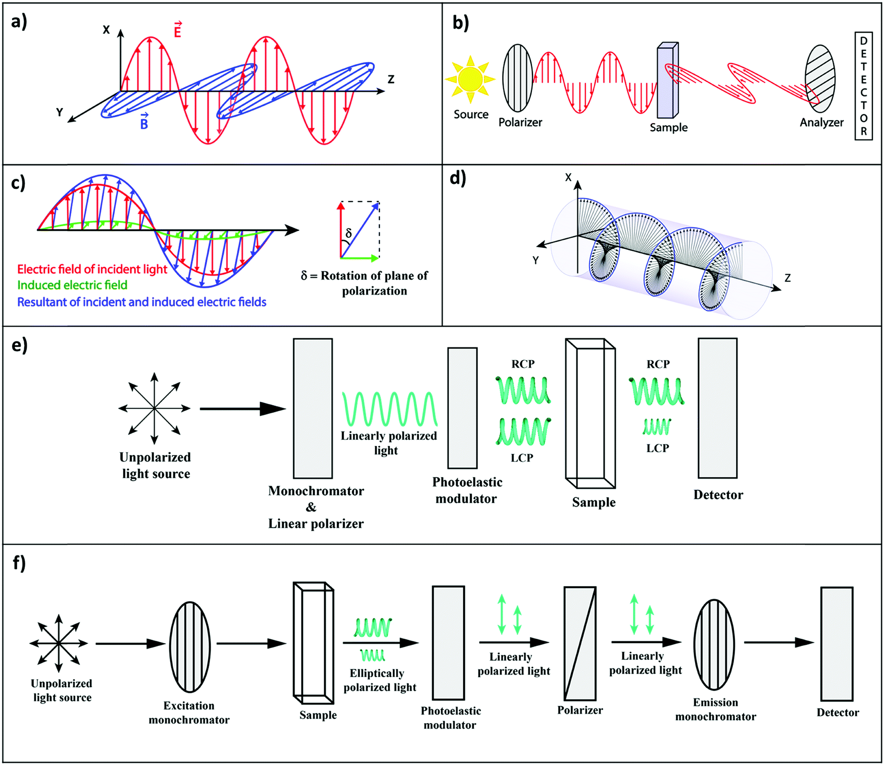 | ||
| Fig. 1 (a) Linearly polarized light having its electric (red) and magnetic (blue) vectors, orthogonal to each other (electric field polarized along the x-axis). (b) Optical rotatory dispersion (ORD) experiment: the plane of the polarization of the incident light is rotated in a chiral medium. (c) Rotation of the polarization plane in an ORD experiment illustrating the electric field of the incident linearly polarized light (red), the electric field induced by the magnetic field (green) in a chiral medium, and the resultant field (blue). (d) Circularly polarized light: a combination of two linearly polarized light beams (with the same amplitude), with orthogonal polarization and a phase difference of π/2. (e) Electronic circular dichroic (CD) spectrometer: linearly polarized light is converted to right and left circularly polarized light (RCP and LCP, respectively) by a photoelastic modulator. The chiral medium selectively absorbs the LCP in the present case, which generates an elliptically polarized light. The CD spectrometer measures ellipticity. (f) Circularly polarized luminescence (CPL) measurement: the sample is excited with a monochromatic light, the emitted light then goes through a circular analyzer (a photoelastic modulator followed by a linear polarizer). The photoelastic modulator works at a very low-frequency, alternatively turning the left- or right-circularly polarized light into linearly polarized light that, going through the linear polarizers, finally reaches the monochromator and the detector. | ||
To understand this issue, we should consider the nature of light in more detail. A linearly polarized light, propagating along the z-direction, not only has an electric field oscillating along x, but also a magnetic field oscillating along y (Fig. 1a). The rotation of the polarization of light in a solution of chiral molecules can then be explained if the oscillating magnetic field is able to generate oscillating electric dipoles along the same direction. Such a mixed response, i.e., the oscillating electric dipole generated by the magnetic field of the incident radiation (Fig. 1c), requires non-vanishing rotational strengths (Reg):2,3
Reg = Im(〈g||e〉·〈e|![[m with combining circumflex]](https://www.rsc.org/images/entities/i_char_006d_0302.gif) |g〉) |g〉) | (3) |
is the magnetic dipole operator (again a vectorial quantity) and Im amounts to the imaginary part of the complex number in parenthesis. To have a non-vanishing rotational strength, then at least one of the products 〈g|a|e〉〈e|a|g〉, with a = x, y or z, must be different from zero, or, in other terms, both 〈g|a|e〉 and 〈e|a|g〉 must be different from zero along the same direction. Accordingly, for at least one direction (x, y, or z), the components of the electric and magnetic dipoles must transform as the same irreducible representation in the molecular symmetry group. However, the electric and magnetic dipoles have different symmetry properties with respect to the reflection planes (see Fig. 2). The electric dipole is related to the position of charges, it is a true vector that changes sign upon reflection on a plane perpendicular to the vector (horizontal mirror) and is invariant upon reflections on a plane parallel to the dipole (longitudinal mirror). The magnetic dipole is instead related to the rotation of charges; it is a pseudovector and does not change sign upon reflection on a horizontal mirror, while it is inverted upon reflection on a longitudinal mirror. Therefore, finite rotational strengths in eqn (3), and hence chiral behavior, are only observed in molecules whose symmetry group does not contain any improper axis of rotation (that includes reflection planes and inversion centers), thus providing a strict, symmetry-based definition of chiral systems.3
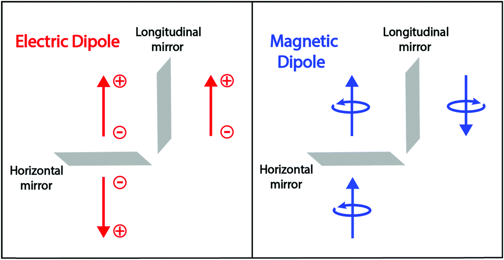 | ||
| Fig. 2 Left panel: The electric dipole is related to the position of positive and negative charges. It is invariant for a reflection on a longitudinal mirror (parallel to the dipole) and changes sign for a reflection on a horizontal mirror (perpendicular to the dipole). Right panel: A magnetic dipole is generated by a rotating charge and its sign is defined based on the right-hand rule. Since the rotation direction is reverted upon reflection on a longitudinal mirror, the magnetic dipole changes its sign upon longitudinal reflection. In contrast, the reflection on the horizontal mirror leaves the rotation unaffected and the magnetic dipole is invariant for horizontal reflection. | ||
Optical rotatory dispersion (ORD) and electronic circular dichroism (CD) are the most commonly used spectroscopic methods to probe chiroptical responses. ORD (Fig. 1b) measures the difference between the medium refractive index for left- and right-circularly polarized light (Fig. 1d), whereas CD (Fig. 1e) reports the difference between extinction coefficients for left and right circularly polarized light, εL − εR (sometimes expressed in terms of molar ellipticity).4 The two measurements are related much in the same way as the refractive index and the extinction coefficient are connected by the Kramers–Kröning relations.
The intensity of each transition in absorption and CD spectra is proportional to the oscillator strength (eqn (2)) and to the rotational strength (eqn (3)), respectively. Of course, signals observed in absorption spectra are always positive, while CD signals can be positive or negative depending on the sign of the rotational strength. Two well-known sum rules apply to absorption and CD spectra: (i) the oscillator strength, summed over all excited states, provides the total number of electrons (the Thomas–Reiche–Kuhn sum rule),1 while (ii) the rotational strength in the whole electromagnetic spectrum sums up to zero.2
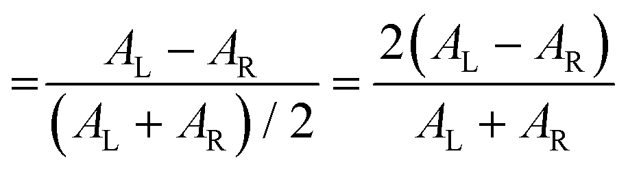
The polarization efficiency can be measured using the dissymmetry factor (gCD), a dimensionless quantity defined as the difference between the absorbance of left- and right-circularly polarized light (AL/R), divided by the absorbance of non-polarized light (A) at a given wavelength:
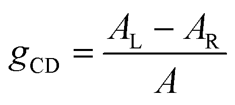 | (4a) |
 | (4b) |
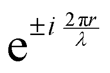 , appears in the description of the radiation field, where i is the imaginary unit, r the position vector and λ the light wavelength (ESI†). Since r cannot exceed the molecular size (typically ∼1 nm), in the visible region (λ = 400–700 nm) 2πr/λ ≪ 1 and the exponential is safely approximated to 1. In this so-called dipole (or long wavelength) approximation,1,2 only the electric field and hence the electric dipole moment enter into play. To introduce a magnetic field, as needed to account for the chiroptical phenomena, one must consider the subsequent term,
 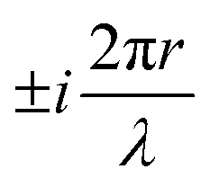 in the expansion of the exponential. As a result, chiroptical signals (proportional to r/λ) are very small and define spectroscopic techniques of low sensitivity. In plasmonic systems, the structures of interest are bigger making the electric dipole approximation poor, explaining larger dissymmetry factors as well as the need to go for multipolar expansions (ESI†).
An excited molecule can relax to the ground state by emitting light in a process called luminescence. In analogy with CD spectra, circularly polarized luminescence (CPL) measures the difference between the intensity of the emitted left- and right-circularly polarized light (LL/LR), as illustrated in Fig. 1f. To avoid the experimental subtleties related to the measurement of absolute emission intensities, the chiroptical response of an emissive medium is quantified using the dissymmetry factor, glum. In strict analogy with the absorbance dissymmetry factor in eqn (4), glum is defined as the difference between the intensity of the left- and right-circularly polarized emission (LL − LR) divided by the averaged emission intensity at a given wavelength:6
 | (5) |
Absorption always occurs from a state at thermal equilibrium, so there are no competitive processes. Luminescence instead occurs from an excited state. Hence several processes, e.g., relaxation, conformational changes, reorientation etc., may occur before luminescence takes place. For allowed transitions (i.e., transitions from states with sizable transition dipole moments), fluorescence is observed with typical lifetimes of the order of few nanoseconds. In this timescale, the excited molecule undergoes internal conversion, and relaxes towards the so-called fluorescent state, i.e., the lowest excited state with the same spin multiplicity as the ground state. Fluorescence and CPL then only involve the fluorescent state in its equilibrium geometry. In liquid solutions, the molecules tumble around quickly, and the solvent has time to relax around the excited molecules before fluorescence takes place. Under these conditions, the CPL dissymmetry factor is related to the rotational strength as follows:6
 | (6) |
![[m with combining circumflex]](https://www.rsc.org/images/entities/b_i_char_006d_0302.gif) |g〉|2 is often negligible with respect to |μeg|2. The important point here is that CPL may only occur from the lowest excited state with the same multiplicity as that of the ground state, so that in the above equation e refers to the fluorescent state.
|g〉|2 is often negligible with respect to |μeg|2. The important point here is that CPL may only occur from the lowest excited state with the same multiplicity as that of the ground state, so that in the above equation e refers to the fluorescent state.
After this brief introduction, we now focus our discussions on the emergence of chiroptical signatures in molecular and plasmonic systems. We propose a few broad classifications that are useful to obtain a general understanding on the molecular chirality and its parallels with plasmonic chirality.
1.1. Chiral structures: general classification.
Chiroptical signatures are observed in molecular systems that are conveniently classified as (i) inherently chiral molecules, due to the presence of a chiral site or a chiral axis, (Fig. 3a and b)8,9 and (ii) systems in which achiral molecular units are arranged in chiral supramolecular structures (Fig. 3c and d).10,11 Chiral inorganic nano-objects based on plasmonic nanoparticles, transition-metal oxides, and silica, are also of recent interest and extensive reviews are available on these topics.12–14 Chiral plasmonic nanostructures are briefly introduced in the last section of this tutorial, highlighting the analogies, along similar lines as recently discussed for achiral systems.15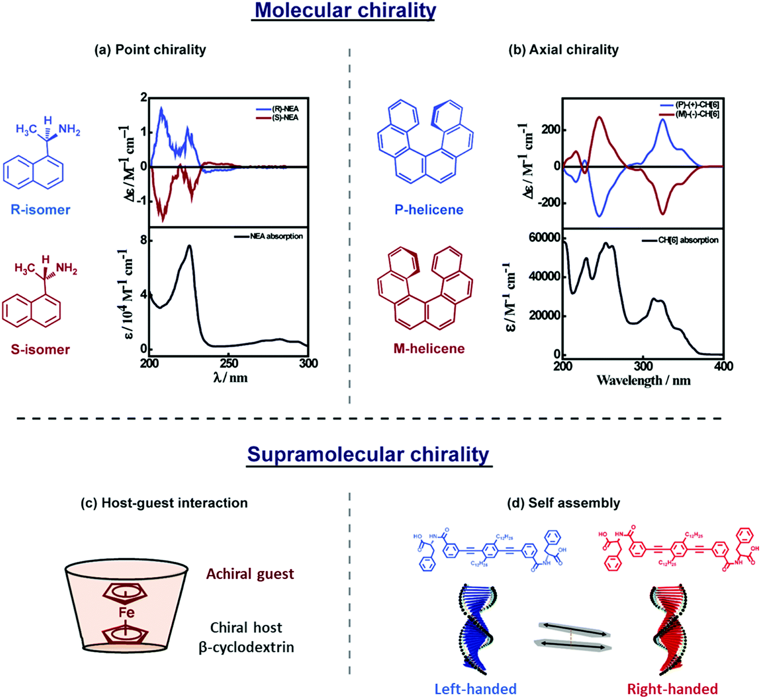 | ||
| Fig. 3 A general description of (a and b) molecular and (c and d) supramolecular chirality. (a and b) Absorption (bottom panel) and CD spectrum (top panel) of molecular systems showing (a) point chirality: molecules having a stereocentre, represented using R- and S-isomers of 1-(1-naphthyl)ethylamine,8 (b) axial chirality: molecules not having a stereocentre but where chirality emerges due to the structure, as in P- and M-helicenes.9 (c and d) Supramolecular chirality arising due to noncovalent interactions: (c) host–guest inclusion complex, represented by ferrocene inside the cyclodextrin cavity, showing induced circular dichroism (ICD)11 and (d) self-assembled molecules in a right- and left-handed helix, represented by the helical assemblies of phenylalanine substituted phenyleneethynylene-based molecular systems, showing exciton coupled electronic circular dichroism (ECD).10 Molecular chirality is beyond the scope of this tutorial and will not be further discussed. | ||
2. Chiroptical spectroscopy in molecular systems
A general classification of molecular and supramolecular chirality is illustrated in Fig. 3. In this tutorial, we focus on supramolecular chirality, i.e., chirality that emerges in supramolecular systems through host–guest complexation (Fig. 3c), or via molecular self-assembly (Fig. 3d).16 The supramolecular organization of molecules results in fascinating dichroic signals, such as induced circular dichroism (ICD) and exciton coupled circular dichroism (ECD), whose origin is discussed below.2.1. Induced circular dichroism
Transfer of chirality can occur from non-racemic chiral compound(s) (host; e.g., cyclodextrin, biomolecular systems, etc.) to achiral molecule(s) (guest; a chromophore) during the molecular or supramolecular organization, as illustrated in Fig. 3c, 4 and 5.11,17,18 This chirality transfer is observed through the emergence of a CD signal in the spectral region of the absorption of the guest (typically in the visible or near-UV), a phenomenon termed induced circular dichroism (ICD).19 The ICD signal emerges mainly due to host–guest interactions resulting in (i) the reduction of the structural symmetry of the achiral guest due to the chiral host in a phenomenon called structurally induced chirality (Fig. 5) or (ii) the coupling between the transition dipole moments of the host and guest (vide infra) without any major structural perturbation of the guest (Fig. 4).11,17 ICD spectra are of great interest, since they are indicators of the absolute configuration of the chiral component, which is often transparent in the UV-visible region. More importantly, ICD provides information on the relative orientation of the host and guest molecules in the complex.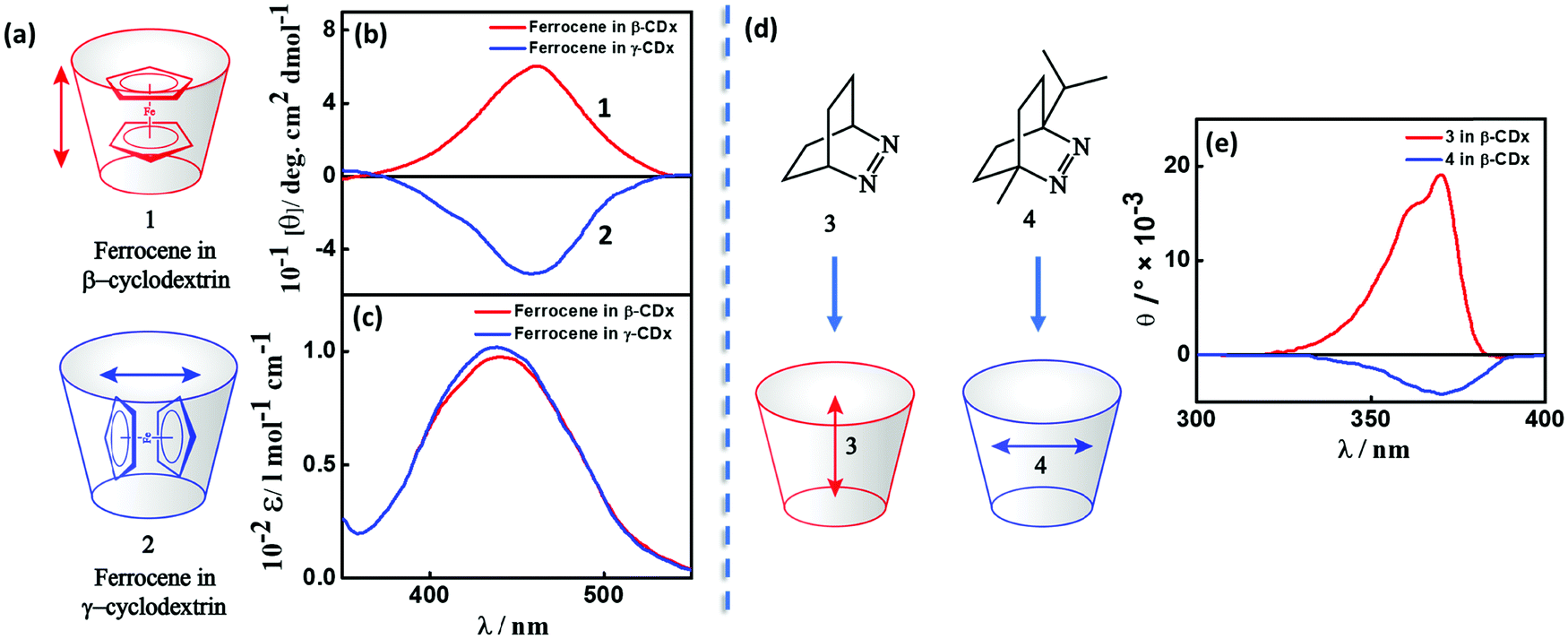 | ||
| Fig. 4 (a and d) Inclusion complexes of dyes in cyclodextrins and (b and e) the corresponding induced circular dichroic (ICD) bands showing positive and negative signals. (a) Inclusion complex and (b) ICD spectrum and (c) absorption spectrum of ferrocene in β- and γ-cyclodextrins, red for complex 1 and blue for complex 2.11 (d) Inclusion of azo-derivatives 3 and 4 in β-cyclodextrin and (e) the corresponding ICD spectrum, red for complex 3 and blue for complex 4.17 The double-headed arrows represent the direction of the transition dipole moment of the guest molecules resulting in a positive (negative) ICD signal when parallel (orthogonal) to the principal axis of the cyclodextrin. | ||
Bisignated CD spectra observed in supramolecular chiral systems result from the dipolar coupling between degenerate (or almost so) transitions residing on identical (or very similar) chromophores, as discussed in detail in Section 2.2. In ICD, instead, the interacting dipoles correspond to transitions relevant to the host and guest species that typically occur in different spectral regions. Accordingly, the ICD spectrum observed in the spectral region relevant to the guest is not bisignated, but shows either a positive or a negative band. Of course, in systems where more than a single chromophore is present, interchromophoric interactions may add to the ICD phenomena leading to more complex spectral features (Fig. 5).
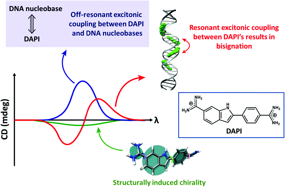 | ||
| Fig. 5 The CD spectra of DNA-bound achiral chromophore DAPI with contributions from resonant excitonic coupling between DAPIs resulting in a bisignated CD signal (red trace), off-resonant excitonic coupling between DAPI and DNA nucleobases (blue trace) resulting in a non-bisignated CD signal in the absorption spectral region of DAPI and structurally induced chirality (green trace). Adapted with permission from ref. 18 Copyright (2017) American Chemical Society. | ||
The rotational strength is proportional to the squared transition dipole moments of the host and guest moieties and inversely proportional to the difference between the squared transition frequencies of the two species, so that it rapidly decreases with increasing the energy difference between the host and guest transitions.20 ICD signals can be enhanced by (i) using host and guest species with large molar extinction coefficients, i.e., large transition dipole moments and (ii) controlling the dynamics of the complex, i.e., by restricting the mutual rotational and translational freedom of the host and the guest. Indeed, restricting the configurational freedom reduces the possibility for the system to attain geometries with opposite rotational strengths leading to a partial cancellation of the signal. A restricted freedom in the host–guest complex may also favour structural chiral perturbations with a chiral conformational preference in the otherwise achiral chromophoric component (structurally induced chirality; Fig. 5).
A classic example of ICD is the complexation between cyclodextrin, a host with specific chirality, and an achiral chromophoric guest, where the dipole–dipole coupling mechanism results in the generation of optical activity for the electronic transitions of the chromophore. Experimental and theoretical investigations on inclusion complexes of cyclodextrins, carried out in the 1970s by several Japanese research groups, resulted in the Harata's rule. The rule states that the ICD of a chromophore confined in the cavity of a cyclodextrin will be always positive (negative), if its electric transition dipole moment is parallel (perpendicular) to the principal axis of the cyclodextrin.21 For example, the sign of the ICD spectrum of the inclusion complexes of ferrocene in cyclodextrins (1 and 2) is dictated by the orientation of the guest molecule within the cavities of β- and γ-cyclodextrins (Fig. 4a–c),11 established through NMR studies. Analogously, the sign of the ICD spectrum depends on the orientation of azoalkenes 3 and 4 in the cavities of β-cyclodextrin, as presented in Fig. 4d and e.17,22 These studies are important as they provide a simple way to establish the geometry of the chromophore in the cyclodextrin complexes from the sign of the ICD spectrum.
2.2. Exciton coupled circular dichroism (ECD)
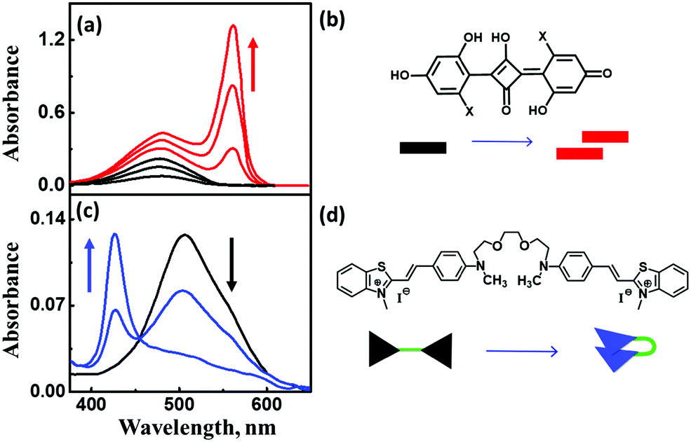 | ||
| Fig. 6 (a) Concentration-dependent aggregation of a squaraine dye (1.2–13.3 μM) and the corresponding absorption spectral changes, (c) solvent-dependent folding of a bichromophoric cyanine dye in mixtures of toluene and dichloromethane, and the corresponding absorption spectral changes. Molecular structure and schematic illustration of the molecular stacking of (b) squaraine dye as J-aggregates and (d) cyanine dyes as H-aggregates. Adapted with permission from ref. 24 Copyright (2018) American Chemical Society. | ||
The exciton model considers a single excited state per molecule and only accounts for intermolecular interactions between degenerate states. In the dipolar approximation, the interaction between transition dipole moments on nearby molecules is the driving force for the delocalization of the molecular excitation and the redistribution of oscillator strength (exciton coupling). In a dimer composed of two equivalent molecules, the two degenerate singly excited states recombine due to intermolecular interactions into two new states representing the in-phase and out-of-phase combination of the two original states. The new states are separated by an energy gap equal to twice the interaction energy (V) between the transition dipoles (Fig. 7). In larger aggregates, exciton bands develop whose width is 4V. For aggregates of perfectly aligned molecules, optical transitions are only allowed towards states where all dipoles oscillate in-phase, resulting in (i) a red-shift (bathochromic shift) of the absorption and fluorescence bands in J-aggregates and (ii) a blue-shift (hypsochromic shift) of the absorption band in H-aggregates, as shown in Fig. 7. In H-aggregates, a large suppression of fluorescence intensity is also observed. In this tutorial, we will not address vibronic bandshapes in H- and J-aggregates, a topic that requires sophisticated non-adiabatic calculations.25–27 As discussed by Spano and coworkers, the vibronic band shapes of exciton bands provide valuable information on exciton delocalization.26 Of course, it is possible to smoothly move from H- to J-aggregates via a controlled slippage of the molecules, so that the sign of V changes from positive (H-aggregates) to negative (J-aggregate), going through a situation with vanishing interaction (null aggregate). In twisted geometries, null aggregates are found when the two molecules are perpendicularly oriented.28 In more complex systems, such as two-dimensional aggregates, null-aggregates may be observed due to the competition of interactions along different directions.29
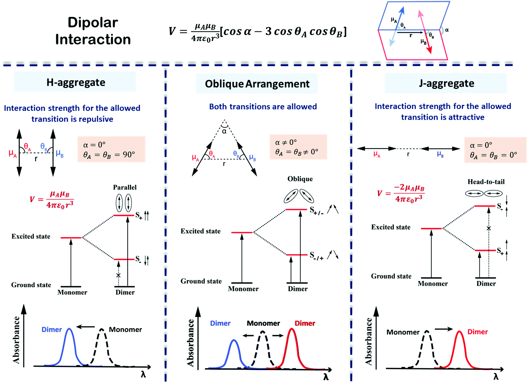 | ||
| Fig. 7 Interaction energy and spectral shift for aligned (H- and J-) and twisted arrangements of transition dipoles in an exciton coupled dimer of identical chromophores. The excited states split on exciton coupling. Transitions are only allowed if the vectorial sum of transition dipoles is different from zero. Allowed and forbidden transitions are represented using solid and broken arrows, respectively. The sign of the interaction, V, is determined by the dimer geometry, according to the expression in the top panel. Absorption spectra, highlighting the exciton shifts, are sketched in the bottom panels. Left column: H-Aggregates have repulsive interactions (V > 0), the bright state is formed in the short wavelength region (blue shift) with respect to the monomer; Middle column: For twisted geometry, V can be either positive or negative, depending on the geometrical details, and both exciton states are optically allowed (leading to the formation of two absorption peaks on both sides of the monomer absorption whose relative intensity depends on the geometry); Right column: J-Aggregates have attractive interactions (V < 0) and the bright state is formed in the long wavelength region (red shift) with respect to the monomer. Also, refer video in the ESI.† | ||
Aligned arrangements of molecules in dimers and macroscopic structures are aesthetically appealing; however, twisted molecular arrangements (central panel of Fig. 7) result in fascinating chiroptical properties. Perfectly aligned arrangements of dipoles are characterized by high symmetry, with a reflection plane or an inversion center, precluding chirality. In twisted geometries, the symmetry is lowered resulting in chiral systems (middle panel of Fig. 7) where chiroptical responses are observed, like the differential absorption and emission of circularly polarized light, measured in CD and CPL, respectively. Helical and creeper-helical aggregates (henceforth called creeper), schematically represented in Fig. 8, are typical models of chiral supramolecular structures, with repulsive and attractive interactions, respectively. In this tutorial, we discuss the origin of chiroptical features in these supramolecular systems, focusing attention on the relation between the sign of the CD spectra and the handedness of the structure, critically addressing the chirality rule proposed by Nakanishi et al.30,31 Meijer and coworkers have extensively contributed towards the understanding of the growth mechanism of helical assemblies, particularly the kinetic and thermodynamic control, by following the CD spectrum,32 but these aspects are beyond the scope of the present discussion.
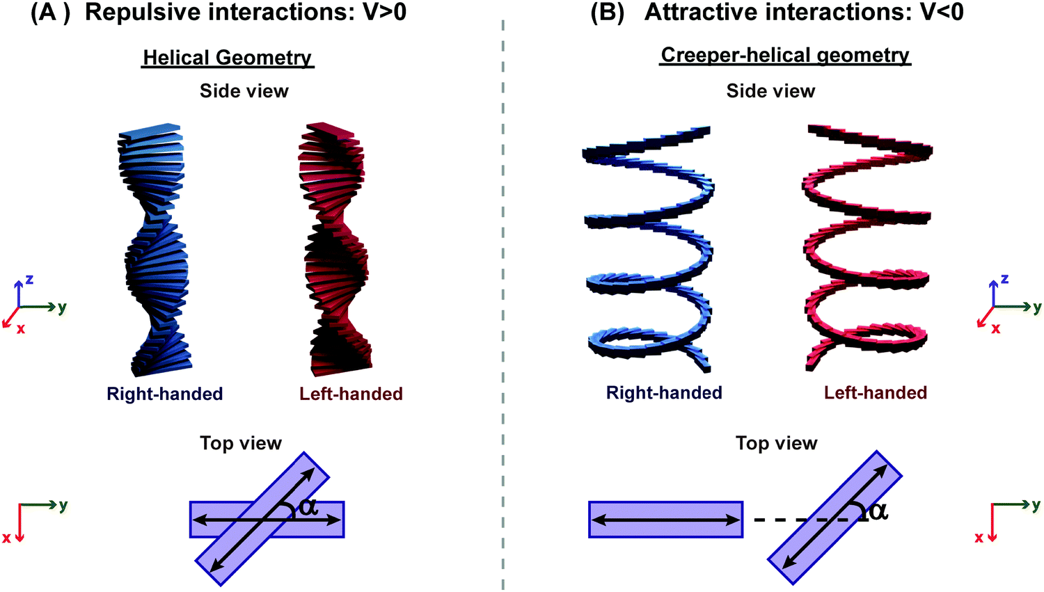 | ||
| Fig. 8 Illustration of molecular aggregates with a twisted dipole arrangement: (A) helical geometry with repulsive interactions and (B) creeper–helical geometry (henceforth called creeper) with attractive interactions. Note: α is the angle between the transition dipoles.31 Also, refer video in the ESI.† | ||
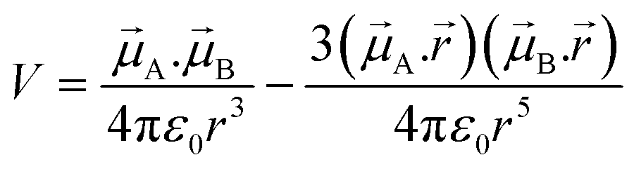 | (7) |
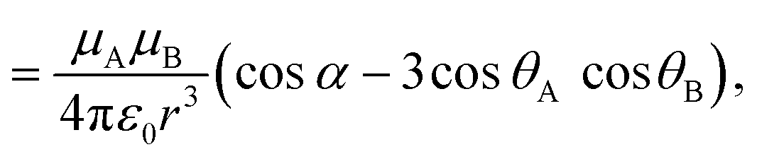 | (8) |
![[small mu, Greek, vector]](https://www.rsc.org/images/entities/i_char_e0e9.gif) A and B are the transition dipole moments associated with the two molecules, μA and μB are the corresponding magnitudes, the angles α, θA and θB are defined in Fig. 7,
A and B are the transition dipole moments associated with the two molecules, μA and μB are the corresponding magnitudes, the angles α, θA and θB are defined in Fig. 7, ![[r with combining right harpoon above (vector)]](https://www.rsc.org/images/entities/i_char_0072_20d1.gif) is the vector connecting molecule A with molecule B, and r is its magnitude.
is the vector connecting molecule A with molecule B, and r is its magnitude.
For small interactions, V ≪ E, the mixing among the non-degenerate states can be neglected (Heitler–London approximation). Accordingly, only the two degenerate states at energy E are mixed, to give two states with energies:
| E± = E ± V | (9) |
The corresponding eigenstates are the in-phase and out-of-phase combinations of the two degenerate states:
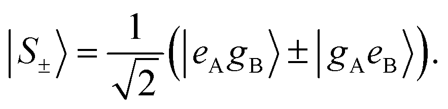 | (10) |
Two different transitions can then be considered for the dimer: G → S+ and G → S−. The relevant transition dipole moments (±) are linear combinations of the transition dipole moments of the individual molecules as presented in eqn (11).
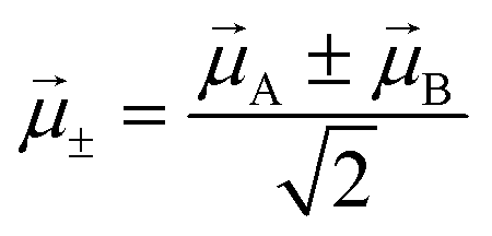 | (11) |
For identical molecules with aligned dipoles the state |S−〉 has a vanishing transition dipole moment, while the squared transition dipole moment towards state |S+〉 is 2μ2. In other terms, since the intensity of the transition is proportional to the squared transition dipole moment, in a dimer with parallel molecules (H- and J-aggregates), the intensity associated with the two molecules concentrates into a single G → S+ transition. This corresponds to the lowest energy transition in J-aggregates, and to the highest energy transition in H-aggregates (see Fig. 7).
The exciton coupling in a supramolecular assembly is detected by a bisignated CD spectrum. The exciton model explains the origin of the bisignated CD spectra as illustrated in Fig. 9 for a helical dimer with V > 0. Specifically, the rotational strength (R±, proportional to the intensity of the CD signals associated with states |S±〉) is defined as:
 | (12) |
 | (13) |
 | ||
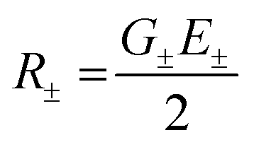
| Fig. 9 Scheme elucidating the origin of CD spectra and their dependence on the system handedness for a helical arrangement of dipoles. In this geometry, V > 0 and S+ is at higher energy than S−. Due to the twisted geometry, both states show up in the absorption spectra (in general with different intensities) and the two states are responsible for the exciton couplet in the CD spectra. The intensity of the CD signals related to the S± states is given by R± in eqn (12), leading to equal and opposite signals for the two states. The direction of the vector product, ±A × ±,B, is obtained using the right-hand rule, explaining the opposite sign for the right-handed and left-handed helices. Also, refer video in the ESI.† | ||
The most important result, however, is that non-chiral molecular units, when arranged in a chiral supramolecular structure, give rise to on-resonance exciton coupling and sizable CD signals. Eqn (12) and (13) points to the bisignated CD spectra related to the opposite sign of R± for the two excitonic states. For the helical arrangements in Fig. 9, the vectors and ±,A × ±,B are parallel and point in the same direction for a right-handed dipole arrangement and in opposite directions for a left-handed arrangement, explaining the sign reversal of the CD spectrum in systems with opposite handedness (Fig. 9). The sign of the Cotton effect is dictated by the sign of the geometric factor, unambiguously defining a relation between the CD spectrum and the supramolecular arrangement. When the molecular transition dipoles are arranged in a right-handed fashion, the CD spectrum shows a positive signal in the long-wavelength region of the spectrum, followed by a negative CD signal in the short wavelength region, the opposite occurring for a left-handed arrangement. This description came handy for characterizing the CD spectra of systems exhibiting exciton coupling and to understand their absolute configuration in an approach that was later termed as the exciton chirality method.33,34 The rule reads, “if the exciton CD shows a positive first and a second negative Cotton effect, then the two electric transition dipole moments constitute a clockwise screw sense and vice versa.”
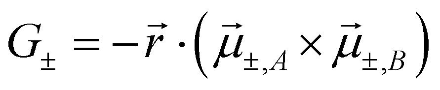
With applications ranging from simple dimers to larger aggregates, the exciton chirality rule is widely employed to study conformation assisted chiroptical properties. Despite its widespread use, the general applicability of the rule has been questioned at times. Recently, this problem has been formally addressed, with reference to the sign of the intermolecular interaction energies in helical and creeper aggregates.31,35 Helical arrangements of molecules result in systems with dominating repulsive interaction between transition dipoles, while attractive interaction dominates in creeper geometry. Exciton model analysis, supported by TD-DFT results, confirmed that the sign of the interaction energy between transition dipoles affects the order of the exciton states and hence the sign of the CD spectra. Fig. 10 explains the dependence of CD spectral features on the geometric parameters in a chiral dimer with attractive interactions (creeper arrangement). In this dimer, the order of the |S±〉 states is reversed with respect to the simple helical dimer, shown in Fig. 9. Accordingly, as detailed in Fig. 10, the chirality rule is reversed in creeper aggregates with respect to helical aggregates. The chirality rule thus offers a powerful and reliable tool to extract the absolute chirality of supramolecular aggregates from the sign of the CD spectra, provided that the sign of intermolecular interactions is properly accounted for. A video highlighting how the sign of bisignated CD signals in circular dichroism is determined by the handedness of the structure as well as by the sign of intermolecular interaction energy is provided in the ESI.†
 | ||
| Fig. 10 Scheme elucidating the origin of the CD spectra and their dependence on the system handedness for a creeper arrangement of dipoles. In this geometry V < 0 and S+ is lower in energy than S−. Due to the twisted geometry both states show up in the absorption spectrum (in general with different intensities) and the two states are responsible for the exciton couplet in the CD spectra. The intensity of the CD signals related to the S± states is given by R± in eqn (12), leading to equal and opposite signals for the two states. The direction of the vector product, ±,A × ±,B, is obtained using the right-hand rule leading to opposite sign for the right-handed and left-handed creeper-helices. Also, refer video in the ESI.† | ||
We have theoretically explained the fundamental principles behind the emergence of bisignation in helical aggregates of molecules where the monomer has a single transition in the spectral region of interest. Taking the phenylalanine substituted phenyleneethynylene systems (L-PE-R and D-PE-R) as an example, we have experimentally demonstrated the dependence of the sign of the bisignated CD signal on the handedness of the assembly. Using the exciton model, we could calculate the CD spectra of large aggregates (up to 10 molecules, even more is possible) while the TD-DFT calculations become very expensive even for three molecules.
The optical spectra of dyes with more than a single transition in the relevant spectral region are complex. In a recent paper, we have addressed the CD spectra of alkyloxy substituted phenyleneethynylene molecules (L-PE-OR and D-PE-OR). This minor change in substitution has a significant impact on optical features (absorption and CD spectra) of both the monomer and aggregate. Specifically, for this molecule, two transitions are observed in a narrow spectral region (300–400 nm), with non-collinear dipole moments (μx and μy in Fig. 11). Consequently, the CD spectrum shows two distinct features: a non-bisignated signal, followed by a bisignated signal. These unusual spectroscopic features are explained using a modified exciton model,10 where we account for the coupling between the degenerate states (corresponding to the μx–μx and μy–μy coupling) and non-degenerate states (corresponding to the μx–μy coupling) as illustrated in Fig. 11A and B.
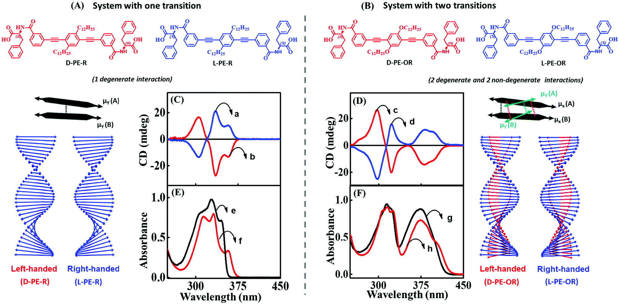 | ||
| Fig. 11 Supramolecular structures composed of molecules with a single transition in the spectral region of interest (left) and with two transitions (right). Molecular system possesses (A) one transition dipole moment in the 300–375 nm spectral region aligned along the main molecular axis of the phenyleneethynylene core (D-PE-R and L-PE-R) and (B) two transition dipole moments in the 300–400 nm spectral region (the presence of an alkoxy group is responsible for a second transition dipole aligned along a different direction (D-PE-OR and L-PE-OR)). Schematic illustration of the helical organization of molecules with one transition dipole moment (extreme left panel) and the corresponding (C) CD and (E) absorption spectra. Schematic illustration of the helical organization of molecules with two transition dipole moments (extreme right panel) and the corresponding (D) CD and (F) absorption spectrum. The blue traces a and d refer to right-handed assemblies (L-PE-R/L-PE-OR), and red traces b and c correspond to left-handed assemblies (D-PE-R/D-PE-OR). The absorption spectrum of the monomeric form of D-PE-R/D-PE-OR is shown as black traces (e and g) and aggregated as red traces (f and h). Adapted with permission from ref. 10 Copyright (2018) American Chemical Society. | ||
3. Plasmonic chirality
Plasmonic oscillations in metal nanostructures such as Ag nanoparticles (henceforth nanoparticles are abbreviated as NPs) and Au nanorods (henceforth nanorods are abbreviated as NRs) describe the fluctuations of the electronic charge density in response to an external electromagnetic field. The interaction with an electromagnetic field has a dipolar character, but depending on the dimensions of the plasmonic structures, multipolar modes can also occur. The dipolar mode in plasmonic nanomaterials can be visualized as the oscillation of conduction electrons against the positive ionic core. Then, the intense absorptions observed for plasmonic NPs in the visible region have the same physical origin as the much weaker absorptions observed for dyes: i.e., induced oscillating dipole moments resonant with the driving field. However, excitons are elementary electronic excitations in molecular systems, whereas plasmons are collective electronic excitations in metallic nanostructures due to the presence of an electron cloud on their surface. Parallels between excitonic and plasmonic excitations have been comprehensively illustrated in a recent perspective.24 As discussed in Section 1, the spectral intensity of an electronic transition is conveniently expressed using the oscillator strength f, a dimensionless quantity defined in eqn (2). When integrated over the entire optical spectrum, f sums up to the total number of electrons in the molecule, so that the oscillator strength associated with a specific transition roughly measures the number of electrons participating in the relevant excitation. Typically, the oscillator strength of allowed transitions in a molecule is of the order of one, implying that roughly one electron is involved in the transition. Collective electronic excitation in plasmonic systems instead involve a large number of electrons leading to huge oscillator strengths. To illustrate this point, Table 1 compares the experimental values of the extinction coefficient, ε, and f for a representative cyanine dye (Cy+, Fig. 12) and its J-aggregate with the corresponding values estimated for representative plasmonic systems (Ag NPs and Au NRs).15 Plasmonic systems are characterized by huge extinction coefficients (ε ∼ 109–1010 M−1 cm−1) and effective oscillator strengths (f ∼ 104–105), confirming the collective nature of plasmonic excitations. Accordingly, plasmonic excitations are characterized by giant transition dipole moments that are responsible for amplified electric fields at the resonant frequencies in proximity of the plasmonic structure. This phenomenon is exploited in a variety of techniques, the most prominent example being surface-enhanced Raman scattering (SERS).36| Excitonic/plasmonic systems | Molar extinction coefficient, ε, M−1 cm−1 (λmax, nm) | Effective oscillator strengthb, (f) |
|---|---|---|
| a Adapted from ref. 15 Copyright (2018) American Chemical Society. b For oscillator strength calculation, see ref. 15. c In methanol refractive index = 1.33. d In water refractive index = 1.33. e Dimensions of Ag NP and Au NR are presented in Fig. 12. | ||
| Cy+ (monomer)c | 3.5 × 10⁴ (524) | 0.38 |
| Cy+ (J-aggregate)d | 1.8 × 10⁶ (570) | 2.88 |
| Ag NPd,e | 2.1 × 10¹⁰ (436) | 4.5 × 10⁵ |
| Au NRd,e | 2.3 × 10⁹ (582) | 2.8 × 10⁴ |
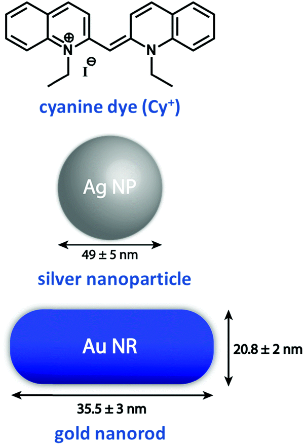 | ||
| Fig. 12 Molecular structure of an excitonic system based on a widely used cyanine dye, namely, 1,1′-diethyl-2,2′-cyanine iodide and plasmonic systems based on Ag NPs and Au NRs.15 Dimensions of Au NP and Au NR used in Table 1 are indicated in this figure. | ||
Along with the advances in the area of supramolecular chirality, the new millennium has witnessed a rapid development in the design of chiroptical systems based on plasmonic materials.14,37,38 Various approaches on the synthesis of chiral plasmonic nanostructures are summarized in recent reviews.12–14,39 Here, we briefly address the emergence of chiroptical signals in plasmonic nanostructures and their assemblies in an attempt to draw a parallel with chiroptical properties in molecular systems, described in previous sections. Much as with molecular systems, chiroptical properties can emerge in three different classes of plasmonic nanostructures: (i) intrinsically chiral plasmonic structures; (ii) non-chiral plasmonic structures where chirality is induced via the interaction with a chiral object, typically a chiral molecule and (iii) chiral arrangement of non-chiral plasmonic nanostructures. We will briefly address the first two chiral systems (Sections 3.1 and 3.2), emphasizing more on supra-plasmonic chiral structures (Section 3.3).
3.1. Intrinsically chiral plasmonic systems
Freestanding chiral plasmonic nanostructures are typically prepared by physical methods, such as lithography. More recently, successful examples of chemical synthetic strategies towards the design of chiral plasmonic structures have been demonstrated. Fig. 13a presents the TEM images of helical Au nanostructures having left- and right-handed chirality, grown by the glancing angle deposition method.40 The CD spectrum of these systems originates from collective plasmonic modes with a specific handedness that extends along the entire structure. These results are analogous to the chiral response of helicenes originating from the electronic orbitals delocalized over the entire helical π-conjugated molecular structure. Indeed, the chiroptical signatures of the helical plasmonic nanostructures are comparable to those of their organic counterparts, P- and M-helicenes (Fig. 3), although their dimensionalities are distinctly different. More recently, Nam and coworkers reported the design of right- and left-handed chiral Au nanostructures with a helicoidal morphology using amino acids and peptides as ligands (Fig. 13b).41 The CD response of these nanoparticles are observed at their plasmon resonance wavelength with a dissymmetry factor as high as 0.2. The origin of the chiroptical responses in these large 3-dimensional helicoids is attributed to the dipolar and multipolar plasmonic modes. Even though these helicoids can be considered as continuous entities, plasmon coupling may also contribute to the chiral responses, depending on the gap characteristics (depth and length) of these nanostructures. Au NRs with chiral wrinkles were reported by Liz-Marzàn and coworkers by adopting the surfactant-assisted growth of anisotropic Au seeds on Au NRs, capped with chiral micelles.42 The templating effect of chiral micelles on Au NRs directs the growth of Au seeds resulting in the formation of inherently chiral Au nanostructures having pronounced chiroptical properties with high dissymmetry factors (∼0.20), and tunability in the visible to near-infrared region (Fig. 13c). Chiral responses in these systems originate from multiple chiral plasmonic modes, due to the presence of sharp wrinkles. All the three sets of nanocrystals discussed in this section are inherently chiral and in general, their chiroptical features emerge from chiral plasmonic modes. Anisotropy in the Au nanocrystal can also lead to chiroptical signal with a bisignated CD spectrum, distinctly different from surface plasmon coupled bisignation due to the helical assemblies of plasmonic nanoparticles (section 3.3). Fan and Govorov have theoretically demonstrated that the chiral distortion of a plasmonic surface creates both splitting and mixing of plasmonic modes with bisignation originating from the mixing between plasmon harmonics with different angular momenta.43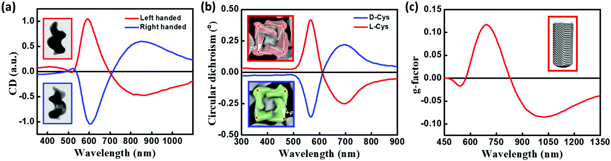 | ||
| Fig. 13 (a) Normalized CD spectra of left-handed (red) and right-handed (blue) helices. Insets show the TEM images of helical Au nanostructures, grown by the glancing angle deposition method, having left-handed (top) and right-handed (bottom) chirality (image dimensions: 85 nm × 120 nm). (b) CD spectra of chiral Au nanostructures synthesized using L-cysteine (red) and D-cysteine (blue). Insets show the SEM image of L-cysteine (red) and D-cysteine (blue) NPs, illustrating the edges (solid lines), title angle −φ/+j with respect to the vertices (red dots), and cubic outline (dashed lines), (c) anisotropy factor for chiral Au NRs having a dimension of 165 × 73 nm grown in (R)-binamine-surfactant (red); inset shows the three-dimensional computer-aided design model, constructed based on the experimental electron tomography reconstructions, showing the intricate network of wrinkles on gold NR surface which is responsible for chirality. Adapted with permission from (a) ref. 40 copyright (2013) Springer Nature, (b) ref. 41 copyright (2018) Springer Nature, (c) ref. 42 copyright (2020), American Association for the Advancement of Science. | ||
3.2. Induced chirality in plasmonic systems
Molecular chirality can be transferred to achiral plasmonic materials through an off-resonance electronic coupling,44–46 a mechanism similar to that described for ICD in chromophoric systems. Most often, the absorption bands of the chiral molecules employed as the source of chirality fall in a spectral region far from the plasmon resonance, ruling out resonant coupling between the molecular and plasmon modes. Much as in molecular systems, however, non-resonant coupling may lead to sizable signals, that may also have a contribution from structurally induced chirality (chiral footprint mechanism).12 Govorov and coworkers have discussed how oscillating dipoles of chiral molecules induce dissipative chiral currents in a nearby plasmonic nanoparticle, thus offering a model for induced chirality in a nanoparticle–molecule complex.44 Induced chirality manifests itself with either a positive or negative monosignated CD signal in the plasmonic spectral region, as observed experimentally through the interaction of Au NPs and Ag NPs with chiral molecules,47 calixarenes,45 and peptides.46 A pictorial representation of chirality induced in plasmonic nanoparticles by a chiral molecule (represented by a chiral carbon centre for simplicity), due to off-resonant exciton–plasmon interaction, is given in Fig. 14. However, as observed when discussing the CD spectrum of DNA-bound achiral chromophore DAPI (Fig. 5), the CD signal of assembled NPs having a chiral molecule in hotspot is more complex (for e.g., Au nanoparticle assembly with double-stranded DNA in the hotspot)48 since it is related to the interplay of different mechanisms that include intrinsic chirality and/or plasmon–plasmon coupling.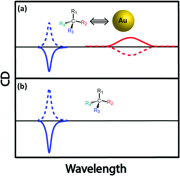 | ||
| Fig. 14 Schematic illustration of chiral induction on an achiral plasmonic NP by the presence of a chiral organic molecule. For simplicity, the chiral molecule is represented by a chiral carbon center. (a) Interaction between an achiral Au NP and a chiral molecule results in a CD response in the plasmonic spectral region of Au NP. The sign of the CD signal depends on the chirality of the molecular system, as well as (in close analogy with induced chirality in molecular systems) on the orientation of an electric dipole of the molecule with respect to the vector connecting the centers of nanoparticle and molecule. (b) an illustration of the CD spectrum of the chiral molecule in the absence of Au NP. | ||
3.3. Surface plasmon coupled circular dichroism
The chiral organization of non-chiral plasmonic structures is the third source of chiroptical responses.49Fig. 15 illustrates the phenomenon with three examples, where the high addressability of the DNA-origami template allowed the precise positioning of non-chiral plasmonic nanostructures as helical superstructures, with right- and left-handedness. Specifically, (i) Fig. 15a–c refers to the helical assembly of Au NRs under the guidance of origami template in a layer-by-layer fashion;50 (ii) Fig. 15e illustrates a helical plasmonic assembly of Au NPs on a tubular DNA origami51 (iii) Fig. 15f and g report the hierarchical assembly of DNA origami building blocks as toroidal structures decorated with Au NPs organized as left- and right-handed helices.52 The resonant plasmonic coupling between individual achiral plasmonic nanostructures in these helices is responsible for the appearance of bisignated CD signals in the spectral region of plasmon resonances (Fig. 15d and g). These signals are strictly analogous to the bisignated signals observed in the CD spectra of chiral supramolecular aggregates of non-chiral chromophores, as discussed in Section 2.2.2. In the subsequent sections, bisignation observed in the CD as a result of resonant plasmon coupling is abbreviated as SP-CD. | ||
| Fig. 15 (a) Schematic illustration of the right-handed (RH) organization of Au NRs using 2D DNA origami. (b) Models and TEM images of RH-organization of Au NRs and (c) the corresponding left-handed (LH) assembly. (d) Experimental CD spectra of RH- and LH-helices containing the ratio of Au NRs to origami as 1.1. (e) Tubular DNA origami containing the helical assembly of Au NPs (top panel) and the corresponding TEM images (bottom panel). (f) Schematic illustration and the TEM images of LH- and RH-plasmonic toroidal systems having a diameter of 120 nm and consisting of 24 Au NPs and (g) the corresponding CD spectrum showing a clear bisignated signal (RH as red trace and LH as blue trace). Adapted with permission from (a–d) ref. 50 Copyright (2015) American Chemical Society, (e) ref. 51 Copyright (2012) American Chemical Society, (f and g) ref. 52 Copyright (2016) American Chemical Society. | ||
There are several other examples wherein handed groupings of individual resonant plasmonic nanoparticles also show SP-CD.53 Growing plasmonic structures on a chiral organic template represents a convenient method for the synthesis of such chiral plasmonic nanostructures.49,54 We have recently demonstrated a template-assisted strategy for the design of Au NP assemblies, organized in clockwise and anti-clockwise directions. This is achieved by growing Au NPs on chiral thermoresponsive organic templates based on D- and L-forms of alanine-functionalized phenyleneethynylenes. In addition to the CD signals of the organic template, the CD spectrum of the Au NP assemblies on template shows bisignated signals in the spectral region of the plasmonic resonance (SP-CD). The chiral organic template directs the growth of the Au NPs with defined handedness, resulting in right- and left-helical arrangements of plasmonic nanoparticles. Upon increasing temperature, the chiral templates dissociate, as demonstrated by the disappearance of the corresponding CD signal, so that free-standing chiral plasmonic nanostructures are obtained, showing a clear SP-CD signal. Even though these free-standing chiral structures could be considered to be inherently chiral from the structural point of view, their CD responses primarily originate from the plasmon–plasmon coupling of individual resonant plasmonic nanoparticles in the helical assembly, as also confirmed by the theoretical analysis. The right-handed helices (Fig. 15 and 16) in all cases show a bisignated SP-CD spectrum with a positive signal in the long-wavelength region, followed by a negative signal in the short wavelength region, which is reversed in the case of left-handed helices. These results are in line with the chirality rule defined in the framework of the exciton model for helicoidal molecular aggregates (see Section 2.2.2).
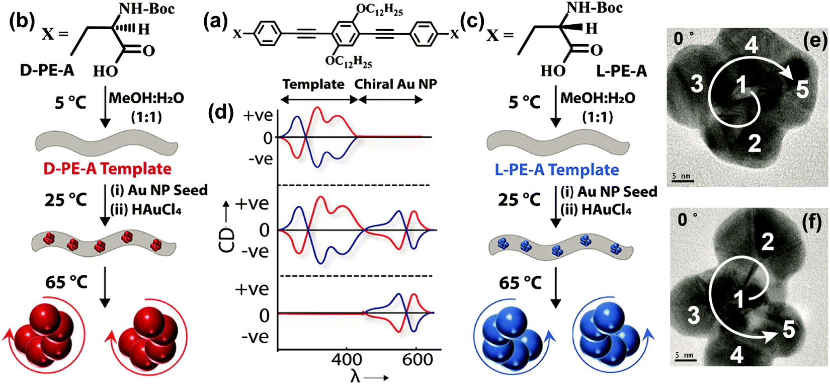 | ||
| Fig. 16 Template-assisted strategies adopted for the design of Au nanostructures having left-handed and right-handed chiral organization. (a–c) Molecular structures of the D- and L-forms of alanine-functionalized phenyleneethynylenes (D-/L-PE-A). (b and c) Schematic representation of the assembly of chiral organic nanotubes from D-/L-PE-A isomers, formation of chiral Au NP assemblies on its surface and removal of chiral nanoparticles from its surface by heating. (d) Corresponding illustrations (top to bottom panels) of the CD response after the formation of (i) chiral organic templates from D-PE-A (red trace) and L-PE-A isomers (blue trace), (ii) formation of chiral Au NP assemblies on the surface and (iii) removal of organic template by heating. TEM images of the (e) P- and (f) M-forms of Au NP assemblies: when the tilt angle is 0°, the arrangement of Au NPs in the frame is in the clockwise direction and in the anticlockwise direction representing the P- and M-forms, respectively, as indicated by the direction of arrows (the numbering and direction of arrows are a guide to the reader's eye). Adapted with permission from ref. 49 Copyright (2019) American Chemical Society. | ||
However, theoretical results tell a different story: indeed, the sign of the CD spectra does not only depend on the helix handedness, but it may be reversed for the same helix, depending on the helix diameter and pitch. This can be hardly reconciled with the exciton model, where, for a given geometry (helix or creeper) the sign of the CD spectrum is determined only by the helix handedness. Although the parallels between exciton and plasmonic chirality are robust, two important differences must be recognized. Apart from very special cases of highly symmetric molecules (e.g., octahedral structures), transition dipole moments in molecular systems typically have a well-defined fixed orientation with respect to the molecular frame. In spherical (or almost so) Au NPs instead, plasmonic oscillations may be driven along any direction, resulting in oscillating dipoles that always oscillate along the same direction as the driving field. The second difference is recognized in the huge transition dipole moments associated with plasmonic excitations, when compared to molecular excitations. As already noticed, large dipole moments imply large local electric fields that sum up to the driving field. In molecular systems, the tiny electric fields generated by the molecular units are just minor corrections to the driving field, and one assumes that each molecule in the aggregate responds to the applied field exactly as it would in the free space (in other terms, the molecular polarizability is neglected). In a plasmonic superstructure instead each NP responds to an electric field which is the sum of the applied field plus the large electric field generated by the surrounding NPs. Of course, this complex self-consistent interplay between largely polarizable NPs becomes more prominent when the distances between the NPs become small, and indeed deviations from the chirality rule are observed for small helix diameters or small pitches.
4. Conclusions
In this tutorial, we have explored the chiroptical responses of chiral supramolecular assemblies and plasmonic nano-objects, in relation to their electronic and structural characteristics, and the less understood parallels between molecular and plasmonic chirality are brought out. The optical responses of achiral molecules and materials are dominated by electric dipole interactions. Specifically, the oscillating electric field of light induces oscillating dipoles in the molecules/materials. As a result, at resonant frequencies, absorption bands appear in the spectrum whose intensity is measured by the oscillator strength, a dimensionless positive quantity proportional to the squared transition dipole moment for each transition. In chiral systems, chiroptical responses (ORD and CD) originate from oscillating electric dipoles induced by the magnetic field of the incident radiation. The resulting (weak) responses can be observed in the presence of chiral species, i.e., objects that are not superimposable to their specular image (technically, objects whose symmetry group does not contain any improper axis of rotation). The oscillator strength, a positive quantity, defines the optical properties and, when integrated over the whole electromagnetic spectrum, it sums to the total electron number. The rotational strength, either a positive or negative quantity, defines the chiroptical properties and sums to zero when integrated over the whole electromagnetic spectrum. The absorption/luminescence polarization efficiency of molecules and plasmonic materials measured by the dissymmetry factor (gCD/glum) is also discussed in this tutorial along with the reasons for the relatively lower gCD values for molecular systems as compared to plasmonic materials.In this tutorial, we devoted special attention to supramolecular or supra-plasmonic chirality, wherein achiral objects assembled in chiral structures show sizable chiroptical responses. Two different mechanisms of supra-structural chirality can be envisaged: induced chirality and exciton (or plasmon) coupled chirality. In induced chirality, the achiral object interacts with a chiral system, and as a result, chirality may be induced by either a geometrical (chiral) perturbation on an achiral object or by the non-resonant coupling between the transition dipole moments of chiral and achiral systems. Chiroptical responses due to exciton or plasmon coupling are observed when identical (or almost so) achiral molecules or plasmonic structures are arranged to form chiral supramolecular or supra-plasmonic assemblies. The resonant interactions between the transition dipole moments of individual units in these assemblies lead to strong bisignated CD signals, compared to the monosignated CD signals typically observed from the off-resonance coupling as in the case of ICD. By following the exciton chirality rule, the handedness of supramolecular structures can be related to the sign of the bisignated CD spectrum, which is defined by the sign of the lowest energy peak in the CD couplet. However, the exciton chirality rule must be considered with care: depending on the sign of the interaction energy between transition dipoles, in fact, structures with opposite handedness may show spectra with the same sign as the CD couplet. These aspects are exemplified using helical and creeper-helical molecular assemblies having the same handedness, but displaying opposite CD signals.
Defining a chirality rule for supra-plasmonic aggregates is more difficult. Indeed, similarities between plasmonic and molecular excitations and their chiral behavior are underlined in this tutorial, but differences must also be appreciated. The most important difference between molecular and plasmonic systems is quantitative: electronic excitation in molecular systems typically have oscillator strength of the order of one, while in plasmonic systems, it is typically 4–5 orders of magnitude larger. These large oscillator strengths are related to giant oscillating dipoles, due to the collective plasmonic excitations in metallic nanostructures, which are in turn responsible for amplified electric fields in the close proximity of the plasmonic structures. In supra-plasmonic structures each nanoparticle then feels a total electric field sum of the driving field plus the large electric fields generated by the oscillating dipoles in nearby nanoparticles, leading to a complex self-consistent problem. In supramolecular structures, instead, the tiny oscillating dipoles in the molecular units give only a negligible contribution to the electric field felt by each molecule. These characteristics, along with the high dissymmetry values, enable the potential applications of chiral plasmonic NPs and NP assemblies in various fields such as chiral amplification, transcription and sensing, enantiospecific separation, chiral catalysis, etc.39,55,56
Supramolecular and plasmonic chirality are indeed fascinating research fields wherein important contributions are yet to come. An open challenge in the field is to develop a universal model, applicable to both molecular and plasmonic chiral systems. Bridging the gap would not only provide a better understanding of chiroptical phenomena but will also help in dealing with mixed plasmonic and excitonic systems on the same platform. The fundamental insight provided herein on the origin of chiroptical properties is useful not only for graduate-level students but also for researchers working in the broad area of molecular and plasmonic chirality.
Conflicts of interest
There are no conflicts to declare.Acknowledgements
The Indo-Italian Executive Program 2017–2019 of Cooperation in Scientific & Technological Cooperation (No. INT/Italy/P-9/2016(ER)) and the dual PhD degree program (S. K.) between IISER-TVM and University of Parma are acknowledged for supporting personnel exchange. K. G. T. thanks the Department of Science and Technology (DST Nanomission), Government of India, for financial support. K. G. T. acknowledges the J. C. Bose National Fellowship of DST. C. S. and A. P. acknowledge support from COMP-HUB Initiative, ‘Departments of Excellence’ program (MIUR, 2018–2022). This research was partly supported by the European Union Horizon 2020 programme under grant agreement no. 812872 (TADFlife).References
- G. C. Schatz and M. A. Ratner, Quantum Mechanics in Chemistry, Dover Publications, 2012 Search PubMed.
- D. Craig and T. Thirunamachandran, Molecular Quantum Electrodynamics; An Introduction to Radiation Molecule Interactions, 1984 Search PubMed.
- E. Condon, Rev. Mod. Phys., 1937, 9, 432 CrossRef CAS.
- N. Berova, L. D. Bari and G. Pescitelli, Chem. Soc. Rev., 2007, 36, 914–931 RSC.
- M. Wakabayashi, S. Yokojima, T. Fukaminato, K.-I. Shiino, M. Irie and S. Nakamura, J. Phys. Chem. A, 2014, 118, 5046–5057 CrossRef CAS PubMed.
- J. P. Riehl and F. S. Richardson, Chem. Rev., 1986, 86, 1–16 CrossRef CAS.
- M. Rajaei, J. Zeng, M. Albooyeh, M. Kamandi, M. Hanifeh, F. Capolino and H. K. Wickramasinghe, ACS Photonics, 2019, 6, 924–931 CrossRef CAS.
- D. F. Plusquellic, R. J. Lavrich, T. Petralli-Mallow, S. Davis, T. M. Korter and R. D. Suenram, Chem. Phys., 2002, 283, 355–370 CrossRef CAS.
- Y. Nakai, T. Mori and Y. Inoue, J. Phys. Chem. A, 2012, 116, 7372–7385 CrossRef CAS PubMed.
- S. Kar, K. Swathi, C. Sissa, A. Painelli and K. G. Thomas, J. Phys. Chem. Lett., 2018, 9, 4584–4590 CrossRef CAS PubMed.
- N. Kobayashi and M. Opallo, J. Chem. Soc., Chem. Commun., 1990, 477–479 RSC.
- C. Gautier and T. Bürgi, ChemPhysChem, 2009, 10, 483–492 CrossRef CAS PubMed.
- M. Hentschel, M. Schäferling, X. Duan, H. Giessen and N. Liu, Sci. Adv., 2017, 3, e1602735 CrossRef PubMed.
- G. Zheng, J. He, V. Kumar, S. Wang, I. Pastoriza-Santos, J. Pérez-Juste, L. M. Liz-Marzán and K.-Y. Wong, Chem. Soc. Rev., 2021, 50, 3738–3754 RSC.
- R. Thomas, A. Thomas, S. Pullanchery, L. Joseph, S. M. Somasundaran, R. S. Swathi, S. K. Gray and K. G. Thomas, ACS Nano, 2018, 12, 402–415 CrossRef CAS PubMed.
- G. Albano, G. Pescitelli and L. Di Bari, Chem. Rev., 2020, 120, 10145–10243 CrossRef CAS PubMed.
- X. Zhang and W. M. Nau, Angew. Chem., Int. Ed., 2000, 39, 544–547 CrossRef CAS PubMed.
- N. Holmgaard List, J. Knoops, J. Rubio-Magnieto, J. Idé, D. Beljonne, P. Norman, M. Surin and M. Linares, J. Am. Chem. Soc., 2017, 139, 14947–14953 CrossRef CAS PubMed.
- S. Allenmark, Chirality, 2003, 15, 409–422 CrossRef CAS PubMed.
- W. H. Inskeep, D. W. Miles and H. Eyring, J. Am. Chem. Soc., 1970, 92, 3866–3872 CrossRef CAS PubMed.
- K. Harata, Bioorg. Chem., 1981, 10, 255–265 CrossRef CAS.
- B. Mayer, X. Zhang, W. M. Nau and G. Marconi, J. Am. Chem. Soc., 2001, 123, 5240–5248 CrossRef CAS PubMed.
- R. M. Hochstrasser and M. Kasha, Photochem. Photobiol., 1964, 3, 317–331 CrossRef CAS.
- R. Thomas, J. Kumar, J. George, M. Shanthil, G. N. Naidu, R. S. Swathi and K. G. Thomas, J. Phys. Chem. Lett., 2018, 9, 919–932 CrossRef CAS PubMed.
- N. J. Hestand and F. C. Spano, Chem. Rev., 2018, 118, 7069–7163 CrossRef CAS PubMed.
- F. C. Spano, Acc. Chem. Res., 2010, 43, 429–439 CrossRef CAS PubMed.
- M. Anzola, F. Di Maiolo and A. Painelli, Phys. Chem. Chem. Phys., 2019, 21, 19816–19824 RSC.
- E. Sebastian, A. M. Philip, A. Benny and M. Hariharan, Angew. Chem., Int. Ed., 2018, 57, 15696–15701 CrossRef CAS PubMed.
- N. J. Hestand and F. C. Spano, Acc. Chem. Res., 2017, 50, 341–350 CrossRef CAS PubMed.
- N. Berova, P. L. Polavarapu, K. Nakanishi and R. W. Woody, Comprehensive Chiroptical Spectroscopy: Instrumentation, Methodologies, and Theoretical Simulations, Wiley, 2011 Search PubMed.
- K. Swathi, C. Sissa, A. Painelli and K. G. Thomas, Chem. Commun., 2020, 56, 8281–8284 RSC.
- P. A. Korevaar, S. J. George, A. J. Markvoort, M. M. J. Smulders, P. A. J. Hilbers, A. P. H. J. Schenning, T. F. A. De Greef and E. W. Meijer, Nature, 2012, 481, 492–496 CrossRef CAS PubMed.
- N. Harada, M. Ohashi and K. Nakanishi, J. Am. Chem. Soc., 1968, 90, 7349–7351 CrossRef CAS.
- N. Harada, S.-M. L. Chen and K. Nakanishi, J. Am. Chem. Soc., 1975, 97, 5345–5352 CrossRef CAS.
- P. L. Polavarapu, Chiroptical spectroscopy: fundamentals and applications, Crc Press, 2016 Search PubMed.
- J. Langer, D. Jimenez de Aberasturi, J. Aizpurua, R. A. Alvarez-Puebla, B. Auguié, J. J. Baumberg, G. C. Bazan, S. E. J. Bell, A. Boisen, A. G. Brolo, J. Choo, D. Cialla-May, V. Deckert, L. Fabris, K. Faulds, F. J. García de Abajo, R. Goodacre, D. Graham, A. J. Haes, C. L. Haynes, C. Huck, T. Itoh, M. Käll, J. Kneipp, N. A. Kotov, H. Kuang, E. C. L. Ru, H. K. Lee, J.-F. Li, X. Y. Ling, S. A. Maier, T. Mayerhöfer, M. Moskovits, K. Murakoshi, J.-M. Nam, S. Nie, Y. Ozaki, I. Pastoriza-Santos, J. Perez-Juste, J. Popp, A. Pucci, S. Reich, B. Ren, G. C. Schatz, T. Shegai, S. Schlücker, L.-L. Tay, K. G. Thomas, Z.-Q. Tian, R. P. Van Duyne, T. Vo-Dinh, Y. Wang, K. A. Willets, C. Xu, H. Xu, Y. Xu, Y. S. Yamamoto, B. Zhao and L. M. Liz-Marzán, ACS Nano, 2020, 14, 28–117 CrossRef CAS PubMed.
- X. Wang and Z. Tang, Small, 2017, 13, 1601115 CrossRef PubMed.
- A. Visheratina and N. A. Kotov, CCS Chem., 2020, 2, 583–604 CrossRef CAS.
- W. Ma, L. Xu, A. F. de Moura, X. Wu, H. Kuang, C. Xu and N. A. Kotov, Chem. Rev., 2017, 117, 8041–8093 CrossRef CAS PubMed.
- A. G. Mark, J. G. Gibbs, T.-C. Lee and P. Fischer, Nat. Mater., 2013, 12, 802–807 CrossRef CAS PubMed.
- H.-E. Lee, H.-Y. Ahn, J. Mun, Y. Y. Lee, M. Kim, N. H. Cho, K. Chang, W. S. Kim, J. Rho and K. T. Nam, Nature, 2018, 556, 360–365 CrossRef CAS PubMed.
- G. González-Rubio, J. Mosquera, V. Kumar, A. Pedrazo-Tardajos, P. Llombart, D. M. Solís, I. Lobato, E. G. Noya, A. Guerrero-Martínez, J. M. Taboada, F. Obelleiro, L. G. MacDowell, S. Bals and L. M. Liz-Marzán, Science, 2020, 368, 1472 CrossRef PubMed.
- Z. Fan and A. O. Govorov, Nano Lett., 2012, 12, 3283–3289 CrossRef CAS PubMed.
- A. O. Govorov, Z. Fan, P. Hernandez, J. M. Slocik and R. R. Naik, Nano Lett., 2010, 10, 1374–1382 CrossRef CAS PubMed.
- J.-M. Ha, A. Solovyov and A. Katz, Langmuir, 2009, 25, 153–158 CrossRef CAS PubMed.
- J. M. Slocik, A. O. Govorov and R. R. Naik, Nano Lett., 2011, 11, 701–705 CrossRef CAS PubMed.
- B. M. Maoz, R. van der Weegen, Z. Fan, A. O. Govorov, G. Ellestad, N. Berova, E. W. Meijer and G. Markovich, J. Am. Chem. Soc., 2012, 134, 17807–17813 CrossRef CAS PubMed.
- L. M. Kneer, E.-M. Roller, L. V. Besteiro, R. Schreiber, A. O. Govorov and T. Liedl, ACS Nano, 2018, 12, 9110–9115 CrossRef CAS PubMed.
- J. George, S. Kar, E. S. Anupriya, S. M. Somasundaran, A. D. Das, C. Sissa, A. Painelli and K. G. Thomas, ACS Nano, 2019, 13, 4392–4401 CrossRef CAS PubMed.
- X. Lan, X. Lu, C. Shen, Y. Ke, W. Ni and Q. Wang, J. Am. Chem. Soc., 2015, 137, 457–462 CrossRef CAS PubMed.
- X. Shen, C. Song, J. Wang, D. Shi, Z. Wang, N. Liu and B. Ding, J. Am. Chem. Soc., 2012, 134, 146–149 CrossRef CAS PubMed.
- M. J. Urban, P. K. Dutta, P. Wang, X. Duan, X. Shen, B. Ding, Y. Ke and N. Liu, J. Am. Chem. Soc., 2016, 138, 5495–5498 CrossRef CAS PubMed.
- J. Lu, Y. Xue, K. Bernardino, N.-N. Zhang, W. R. Gomes, N. S. Ramesar, S. Liu, Z. Hu, T. Sun, A. F. de Moura, N. A. Kotov and K. Liu, Science, 2021, 371, 1368 CrossRef CAS PubMed.
- J. George and K. G. Thomas, J. Am. Chem. Soc., 2010, 132, 2502–2503 CrossRef CAS PubMed.
- Y. Y. Lee, R. M. Kim, S. W. Im, M. Balamurugan and K. T. Nam, Nanoscale, 2020, 12, 58–66 RSC.
- N.-N. Zhang, H.-R. Sun, S. Liu, Y.-C. Xing, J. Lu, F. Peng, C.-L. Han, Z. Wei, T. Sun, B. Yang and K. Liu, CCS Chem., 2021, 3, 773–783 CrossRef.
Footnotes |
| † Electronic supplementary information (ESI) available. See DOI: 10.1039/d0cs01583k |
| ‡ Equal authors. |
| This journal is © The Royal Society of Chemistry 2021 |