 Open Access Article
Creative Commons Attribution 3.0 Unported Licence
Continuous flow strategies for using fluorinated greenhouse gases in fluoroalkylations
Wai Chung
Fu
 ab,
Preston M.
MacQueen
ac and
Timothy F.
Jamison
 *a
*a
aDepartment of Chemistry, Massachusetts Institute of Technology, 77 Massachusetts Avenue, Cambridge, MA 02139, USA. E-mail: tfj@mit.edu
bDepartment of Applied Biology and Chemical Technology, The Hong Kong Polytechnic University, Hung Hom, Kowloon, Hong Kong
cDepartment of Research and Development, MilliporeSigma (a division of Merck KGaA), 6000 N. Teutonia Avenue, Milwaukee, WI 53209, USA
First published on 21st May 2021
Abstract
Large quantities of fluorinated gases are generated as intermediates or byproducts from fluorinated polymer production annually, and they are effective ozone depleting substances or greenhouse gases. On the other hand, the incorporation of fluoroalkyl groups into drug molecules or bioactive compounds has been shown to enhance biological properties such as the bioavailability, binding selectivity, and metabolic stability. Extraction of fluoroalkyl sources, including trifluoromethyl and difluoromethyl groups, from the fluorinated gases is highly desirable, yet challenging under regular batch reaction conditions. Flow chemistry is an emerging and promising technique to address long-standing challenges in gas–liquid batch reactions such as insufficient interfacial contact and scalability issues. In this review, we highlight recent advances in continuous flow strategies toward enabling the use of fluorinated greenhouse gases in organic synthesis.
Key learning points1. Fundamental concept and importance of flow chemistry.2. Approaches used to construct continuous flow systems. 3. Recent advances in continuous flow fluoroalkylations using fluorinated greenhouse gases. 4. New reactions and mechanisms of fluoroalkylations. 5. Future perspectives. |
1. Introduction
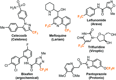
The highly electronegative fluorine atoms pose a strong electron-withdrawing effect and hydrophobic properties when they are bound to a single carbon atom, rendering them an inevitable part in modern pharmaceutical, agricultural, and materials science.1 In particular, fluoroalkyl groups including trifluoromethyl (CF3) or difluoromethyl groups (CF2H) are well-accepted by the medicinal chemistry community as important structural motifs in bioactive compounds. The incorporation of fluoroalkyl groups into molecules could dramatically improve their biological properties such as metabolic stability, lipophilicity, bioavailability and binding selectivity.2–4 The strategy has garnered considerable attention and many therapeutic drugs and agrochemicals bear at least one or more fluoroalkyl groups (Fig. 1). Recent studies have shown that the difluoromethyl group has a character of lipophilic hydrogen bond donor and could serve as a bioisostere for thiols, alcohols and amines.5,6The preparation of the fluoroalkylated compounds were typically achieved by using precursor reagents which deliver the fluoroalkyl groups though a variety of reaction mechanisms, such as photoredox, transition metal-catalyzed, nucleophilic, or electrophilic reactions. A large number of reagents has been developed by numerous research groups, and several reviews have summarized the recent progress in these areas.7–11 Nonetheless, many of the fluoroalkylation reagents are expensive, potentially toxic, have a poor atom economy or require multiple synthetic steps for preparation. In this regard, fluorinated greenhouse gases such as fluoroform (CF3H), iodotrifluoromethane (CF3I) or chlorodifluoromethane (ClCF2H) are undeniably more attractive candidates for highly atom-efficient fluoroalkylations. Harvesting the trifluoromethyl and difluoromethyl sources from these gases for synthesis of APIs (active pharmaceutical ingredients) has the additional benefit of the simultaneous elimination of greenhouse gases. While indeed they have been demonstrated for such purposes, why are they not as widely used as the other commonly employed reagents such as Ruppert–Prakash reagent (TMSCF3)? This tutorial review aims to present the limitations of using the aforementioned fluorinated greenhouse gases in regular batch-mode organic synthesis as well as the continuous flow strategies to solve these problems. We will highlight recent examples, the batch-to-flow transition of the chemistries, and specific techniques used, and provide insights into flow-enabled reactions using the fluorinated gases.
1.1. Limitations of gas–liquid reactions in batch
Large quantities of fluorinated gases are generated as intermediates or byproducts from fluorinated polymer production. For example, fluoroform is a side product from the production of chlorodifluoromethane, which is a refrigerant and an intermediate from PTFE (polytetrafluoroethylene) manufacturing. These fluorinated byproducts are effective ozone depleting substances and/or greenhouse gases, and it is desirable to use them productively. Unfortunately, their use under regular batch chemistry conditions is highly restricted or inefficient. Batch chemistry (or batch synthesis) refers to a series of operations carried out in an organic synthesis to produce chemicals on a batch-by-batch basis, including reaction, purification, and analytical processes. In many chemical laboratories, batch chemistry is conducted using conventional synthetic glassware such as round bottom flasks. In fact, a multitude of the challenges is associated with the solubility of the gases in solution and their handling using conventional glassware. To utilize fluorinated gases in batches, it is common practice to prepare a stock solution by saturating the compound in an organic solvent through continuous bubbling for several hours (Fig. 2A).12 However, the bubbled greenhouse gas could escape from the solvent and re-enter the atmosphere over time, thus rendering a limited shelf-life. Several solvents are commonly employed for this purpose (dimethylformamide (DMF), acetonitrile, 1,4-dioxane), but the reaction medium would be limited, and preparation of multiple stock solutions is laborious. Condensing the gas inside the reaction flask at a low temperature (e.g. −85 °C) is another feasible way, but it demands techniques and subsequent expansion of the gas raises safety concerns. Bubbling the gas directly into the mixture during the course of reaction would lengthen the reaction time and the gas could escape into the system headspace or atmosphere, which is undesirable when using a greenhouse gas. Although conducting the reaction in a closed system (e.g. Schlenk flask, autoclave) could limit the loss of the gas (Fig. 2B and C), the gas–liquid interfacial contact is still insufficient and results in poor mixing efficiency. Moreover, it would be very challenging to establish the correct stoichiometry between the gaseous reagent and substrates due to a number of factors, such as loss of gas, slight volume difference between pieces of glassware, solubility of gases in reaction solvent or human errors during reaction setup. Notably, batch gas–liquid reactions also experience unique challenges when being scaled up to production quantities. For example, addressing safety risks includes quenching of toxic/greenhouse gases, re-optimization of reaction conditions or redesign of reactors. In the past few years, we have observed that there is an emerging trend of using flow chemistry techniques to address these problems. While several review articles have discussed the use of gases in continuous flow synthesis,13–16 fluorinated greenhouse gases have not been covered.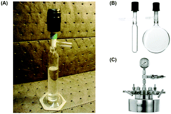 | ||
| Fig. 2 Common equipment used in gas–liquid biphasic reactions under batch conditions: (A) A CF3I-saturated DMF stock solution in a Schlenk graduated cylinder.12 Reprinted with permission from ref. 12, Copyright 2012 American Chemical Society. (B) Schlenk tube and Schlenk flask. (C) Autoclave used in batch organic synthesis. | ||
1.2. Advantages of continuous flow chemistry
For about two centuries, batch chemistry has been the mainstream way of carrying out organic synthesis in many chemical laboratories in both academia and industry. Despite the advancement of analytical and purification instruments, multi-step reactions and purifications are still time- and labor-intensive. Flow chemistry is a powerful synthetic tool which advances chemical synthesis by enhancing productivity while reducing costs and transforming production of fine chemicals. Continuous flow processing increases the control of the key reaction parameters (temperature, mixing, and pressure) and offers new opportunities and many advantages relative to traditional batch synthesis.13–16Fundamentally, flow synthesis is achieved by pumping the solutions of reactants and reagents through microreactors where the chemical reaction is exposed to different conditions such as heating, cooling, or microwave, acoustic or photo irradiation, and products are continuously eluted (Fig. 3). Heat transfer and mass transfer (mixing) are greatly improved as the reaction mixtures are driven through the small channels of microreactors, where the surface area to volume ratio is increased and reaction rates can be raised if the rate-limiting factor of the reaction is mixing or temperature. Temperature of the solutions can be changed extremely rapidly and precisely controlled. Toxic, unstable, and pyrophoric compounds can be generated on demand or handled in very small amounts to mitigate safety hazards, while immediate consumption of these chemicals in flow is highly desirable for reactions dealing with short-lived species. Mixing units and separation modules allow for the streamlining of multiple synthetic steps, safe quenching of toxic chemicals, and in-line purification. The term “in-line” in flow chemistry refers to the flowing stream being manipulated or analyzed without exiting the continuous flow system. Flow systems also have a small footprint, and it is relatively easy to scale up reactions in flow than in batch. Scaling up flow reactions is usually achieved by increasing flow rates, reactor volumes or product collection time.
Importantly, gas–liquid reactions benefit significantly from being transferred to flow and the use of gases in flow is generally easier and more efficient. The lack of system headspace in microreactors and increased interfacial contact area would be highly advantageous to biphasic gas–liquid reactions and could permit previously improbable reaction conditions. The stoichiometry of reagents is critical to many organic reactions, and the introduction of gases to a flow system can be precisely controlled by a mass flow controller (MFC). While there is no head space in a flow reactor, the gases cannot escape the system. Pressurization of flow systems is relatively easy and can be achieved using a back pressure regulator (BPR). The application of high pressure can assist gas dissolution in solutions and solvents can also be heated beyond their boiling points without evaporation. For example, the boiling point of water can reach 203 °C under a pressure of 250 psi.
1.3. Flow equipment
A very basic flow setup includes a pump and a microreactor, but depending on the reaction conditions or requirements, a number of units or equipment could be integrated for different purposes. HPLC systems, peristaltic and syringe pumps are used to deliver solutions into microreactors such as coil, chip or packed-bed reactors (Fig. 3). Plastic, glass or stainless steel syringes can be used and mounted onto the syringe pumps according to the reaction pressure and properties of the chemicals. Coil reactors can be constructed in a modular fashion using PFA (perfluoroalkoxy alkane), PTFE (polytetrafluoroethylene) or stainless-steel tubing, whereas the inner diameter ranges from 0.02 to 0.06 inches for lab scale. Stainless-steel tubing and syringe are recommended for high-pressure and/or high-temperature reactions. Smaller inner diameter generally affords better mixing but is also more prone to clogging by solids. It is noteworthy that clogging is one of the most encountered problems in continuous flow systems. Possible solutions include increasing flow rates and/or inner diameter of channel, diluting the mixture, sonication, as well as increasing temperature or adding a co-solvent to increase the solubility. The counterion also plays an important role. For example, in the case of forming insoluble NEt3·HCl in organic solvent, tributylamine could be used to increase the solubility. For palladium chemistry, increasing ligand loading might prevent the formation of palladium black precipitate. Packed-bed reactors are columns which can be filled with a heterogeneous catalyst (e.g. Pd on carbon), solid reagents, solid-supported reagents, or chemically inert beads for continuous mixing of a biphasic mixture. However, it should be noted that the use of solid-supported reagents and purification materials can offset the continuity of a flow system due to the eventual replacement of consumable materials. In comparison to the reaction time in batch synthesis, the residence time (tR) in flow chemistry is the time reaction mixture spent in the reactor and is dictated by flow rates and reactor volumes (eqn (1)). Y-, T-, cross-mixers and unions are used to join separate streams and connect individual reactors. Check valves enable one-way flow to prevent back-flow of solution and are typically useful in a high-pressure flow reaction. A back pressure regulator (BPR) maintains a constant pressure of a flow system by controlling the area of flow path and is typically placed at the end of the flow system. The liquid fluid has to reach a predefined pressure to pass through the BPR, a pressure of 0–290 psi is usually used in lab-scale reactions depending on the reaction conditions. If insoluble solids aggregate inside the BPR, one possible solution is to introduce a stream of co-solvent to the flow prior to entering the BPR, and the solvent system of the reaction will not be affected. For in-line purifications, a separator can provide continuous separation of immiscible phases, including gas–liquid or liquid–liquid phases, by the differences in the wetting properties of fluids onto a porous membrane. | (1) |
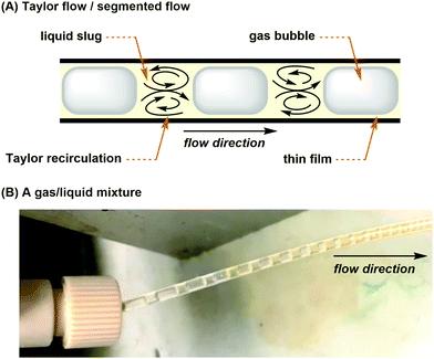
For gas–liquid reactions, a mass flow controller (MFC) can be used and is a programmed device which introduces gaseous compounds to the flow system in an accurate and reproducible fashion (Fig. 4A). The flow rate is measured via the heat transfer between the gas and the thermal sensor in the MFC, and a control valve establishes the flow according to the set flow rate. MFCs can be calibrated to control specific types of gas at a particular range of flow rates. Micro-metering valves are cost-effective alternatives and can also be used to control the size and flow rate of gas bubbles (Fig. 4A), but they are difficult to adjust and are not as accurate as the MFCs. When the separate streams of gas and liquid are joined and driven through a microfluidic channel, segmented flow (or Taylor flow) could be generated (Fig. 5).17 The Taylor recirculation pattern facilitates internal and interfacial mixing while a thin liquid film surrounds the gas bubble and further promotes the saturation. Appropriate pressurization of flow systems using a BPR could eliminate flow segments and keep gases in the solution phase. Alternatively, another widely used approach for the gas–liquid flow chemistry is the tube-in-tube reactor developed by Ley and co-workers (Fig. 4B).13 A Teflon AF-2400 membrane tubing is inserted into a large PTFE tube and connected by T-mixers. Pressurized gases occupy the reactor and diffuse monodirectionally into the inner tube through the membrane and saturate the solution with the gas. A reverse design could be adopted, whereas the gases pass through the inner tubing and the outer solution stream could be exposed to different temperatures and irradiation conditions.
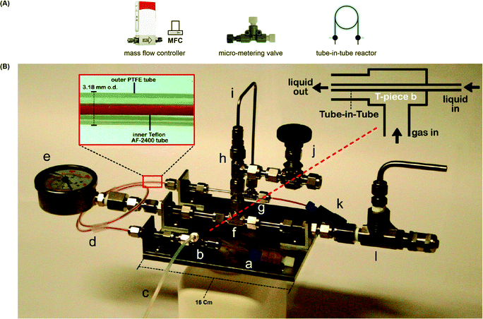 | ||
| Fig. 4 (A) Equipment used in gas–liquid continuous flow reactions. (B) Tube-in-tube reactor used to saturate a flowing liquid with gas.13 Reprinted with permission from ref. 13, Copyright 2015 American Chemical Society. | ||
2. Fluoroform
Fluoroform (CF3H, as known as Freon 23 or HCFC-23) is produced in large quantities each year as an industrial byproduct in the production of chlorodifluoromethane, an intermediate towards the PTFE (polytetrafluoroethylene) product, such as DuPont's Telfon®. CF3H is a colorless gas (b.p. = −82 °C) at room temperature and atmospheric pressure. Although CF3H is not toxic nor ozone depleting, the potent greenhouse gas is 14![[thin space (1/6-em)]](https://www.rsc.org/images/entities/char_2009.gif) 800 times more powerful than carbon dioxide in the atmosphere in terms of GWP (Global Warming Potential) over a 100-year period.18 Under the regulation of the Kyoto Protocol, the release of fluoroform into the atmosphere is prohibited and it has to be collected for incineration or further commodity purposes. Fluoroform is arguably an ideal trifluoromethyl source because it is inexpensive, atom-economical, and readily available, but its chemical inertness is difficult to overcome. The generation of the CF3 anion by proton abstraction of fluoroform is potentially the most straightforward way to harvest the trifluoromethyl source. However, activating CF3H is challenging because the C–H bond of CF3H is weakly acidic with a pKa of 25–28.19 Moreover, the resulting CF3 anion is highly unstable and undergoes α-elimination rapidly to give singlet difluorocarbene and fluoride ion, but this situation could be taken as an advantage for difluoromethylation reactions in certain cases. Considerable progress in the activation of fluoroform under batch conditions was made in the past decades from the 1990s, and they were reviewed recently.20 Here, we will focus on the examples that were adopted in continuous flow to show the transition from batch to flow and their improvements in different aspects including procedures and reaction efficiency.
800 times more powerful than carbon dioxide in the atmosphere in terms of GWP (Global Warming Potential) over a 100-year period.18 Under the regulation of the Kyoto Protocol, the release of fluoroform into the atmosphere is prohibited and it has to be collected for incineration or further commodity purposes. Fluoroform is arguably an ideal trifluoromethyl source because it is inexpensive, atom-economical, and readily available, but its chemical inertness is difficult to overcome. The generation of the CF3 anion by proton abstraction of fluoroform is potentially the most straightforward way to harvest the trifluoromethyl source. However, activating CF3H is challenging because the C–H bond of CF3H is weakly acidic with a pKa of 25–28.19 Moreover, the resulting CF3 anion is highly unstable and undergoes α-elimination rapidly to give singlet difluorocarbene and fluoride ion, but this situation could be taken as an advantage for difluoromethylation reactions in certain cases. Considerable progress in the activation of fluoroform under batch conditions was made in the past decades from the 1990s, and they were reviewed recently.20 Here, we will focus on the examples that were adopted in continuous flow to show the transition from batch to flow and their improvements in different aspects including procedures and reaction efficiency.
2.1. Trifluoromethylations
In 2012, Prakash and co-workers made a ground-breaking contribution in the deprotonation of fluoroform and reported the direct nucleophilic trifluoromethylation of carbon, silicon, boron, and sulfur electrophiles (Fig. 6).21 They found KHMDS (potassium hexamethyldisilazide, pKa = 26) as an effective base to deprotonate fluoroform at very low temperatures (−40 to −85 °C) and the resulting CF3 anion was proposed to immediately react with the electrophiles. Using K+ as the cation of the base was found to be important, while the reactions using NaHMDS and LHMDS failed to give any desired products. Silyl chlorides (R3SiCl) were converted to trifluoromethylated silanes in toluene (42–44% yield) and non-enolizable ketones were trifluoromethylated in diethyl ether (38–78% yield). Aldehydes were also applicable substrates when THF and KOt-Bu were used. Trifluoromethylated trifluoroborate salt (CF3BF3K) and triflic acid (CF3SO2H) were prepared from trialkyl borate (B(OR)3) and sulfur (S8) in good to excellent yields, respectively. In general, fluoroform (1 equiv.) was bubbled into the reaction mixture for minutes to hours, depending on the substrates, before the addition of KHMDS and stirred at room temperature for 10 to 16 hours. Although the fluoroform could be retained in the solution at low temperatures such as −78 °C, it is anticipated that the reaction might encounter scalability problems as a temperature gradient would form across the mixture, in which it could affect the deprotonation process or fail to hold the fluoroform at a larger scale.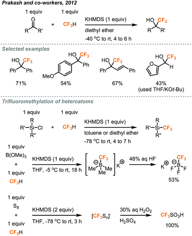 | ||
| Fig. 6 Trifluoromethylation of carbon, silicon, boron, and sulfur centers.21 | ||
The discharge of fluoroform into the atmosphere during or after the course of reaction is undesirable and regulated. Ley and co-workers showed that the use of in-line NMR (nuclear magnetic resonance) and FT-IR (Fourier-transform infrared spectroscopy) monitoring could enable safe and efficient consumption of fluoroform in nucleophilic trifluoromethylations (Fig. 7).22 Fluoroform was introduced into a tube-in-tube reactor (inner tubing: Teflon AF-2400; outer tubing: PTFE) at 44 psi and THF was pumped into the inner tube of the reactor. The fluoroform-saturated THF was then mixed with separate streams of KHMDS (1 M in THF) and ketone substrate (1 M in THF) at a cross-mixer and the combined mixture was directed into a PTFE coil reactor. It is noteworthy that the mixing zone and reactor were both maintained at −20 °C to suppress fluoride elimination of the CF3 anion. The FT-IR installed after the reactor was used to monitor whether the steady state of the flow system is reached using PhCF3 as the internal standard. The mixture was then flowed through an in-line benchtop NMR where 19F NMR spectra were recorded. In-line NMR analysis determined the concentration of fluoroform dissolved in the solution (0.738 M) and was used to optimize the consumption of fluoroform. A BPR (75 psi) was placed at the end of the system to prevent the evaporation of fluoroform and to ensure a homogeneous mixture. Complete consumption of fluoroform was achieved in flow while the efficiency is much higher than the analogous batch method,21 in terms of control of fluoroform dosing and production rate (4.6 vs. 0.225 mmol h−1). DMF and KOt-Bu were used as the solvent and the base for the flow reaction of aldehydes to provide trifluoromethylated alcohols in 75–97% yield within 27 minutes (Fig. 7). Interestingly, the authors have observed by in-line NMR analysis that TMS-protected alcohol was formed first before deprotection to give the trifluoromethylated products, but the theoretical side product TMSF was not observed on 19F NMR spectra. The authors then integrated a silylation module between the in-line FT-IR and NMR for derivatization of alcohols (Fig. 8). A fourth stream of TMSCl (0.3 M in THF) was mixed with the solutions at the output of FT-IR and the resulting solution was directed to another PTFE coil to yield O-trimethylsilyl fluorinated ethers in good to excellent yields within a total tR of 36.6 minutes. Using system illustrated in Fig. 7, triethylsilyl chloride (TESCl) was also successfully trifluoromethylated. The flow conditions for synthesis of TESCF3 was re-optimized with real-time monitoring of the reaction mixture and it was found that a longer residence time (57 min) and lower temperature (−40 °C) were needed. Complete consumption of fluoroform was achieved for both cases.
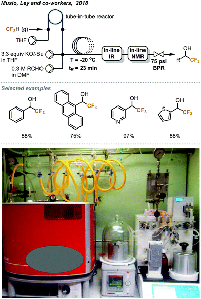 | ||
| Fig. 7 Ley's continuous flow trifluoromethylation of aldehydes with complete consumption of fluoroform.22 Reprinted with permission from ref. 22, Copyright 2018 American Chemical Society. | ||
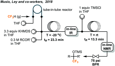 | ||
| Fig. 8 Telescoped system for synthesis of O-trimethylsilyl fluorinated ethers.22 | ||
Recently, the Shibata group reported a rapid trifluoromethylation of aldehydes, ketones, and N-sulfinylmines using fluoroform in continuous flow.23 As shown in Fig. 9, fluoroform was accurately delivered at atmospheric pressure into the flow system by a mass flow controller and mixed with a stream containing the ketone and KOt-Bu at a Y-mixer. Although an excess amount of fluoroform was used (1.7 equiv.), the residence time for the reaction mixture in the stainless-steel coil reactor was only 0.5 seconds. Notably, the ultra-short residence time enabled the reaction to proceed at room temperature and give trifluoromethylated products in moderate to excellent yields (35–98% yield). Similarly, aldehydes were also trifluoromethylated in 1.3 seconds using KOt-bu as base while flow reactions of chalcones and N-sulfinylimines completed within 0.5 seconds using Prakash conditions (KHMDS, toluene). In a comparison, the Shibata flow method provided the trifluoromethylated alcohols with the highest production rate (35.3 mmol h−1). The Shibata group further evaluated the potential of their method for the synthesis of Efavirenz, a medication to treat human immunodeficiency virus (HIV) infection. It should be noted that using the Prakash conditions (KHMDS/toluene) at sub-zero temperatures in continuous flow could lead to clogging because of the precipitation of KHMDS. In this case, a change of solvent to THF could solve the problem.
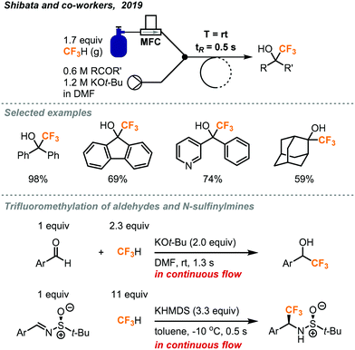 | ||
| Fig. 9 Rapid continuous flow trifluoromethylation using fluoroform gas.23 | ||
As trifluoromethyl anion is highly unstable and has to be generated under low temperature to avoid α-elimination, its strict deprotonation conditions and highly nucleophilic nature might limit the substrate scope, choice of reaction solvent, as well as compatibility with other reagents. An alternative is metalation of fluoroform to generate stable trifluoromethyl organometallic species that give wider access to a range of reactions, substrates, and electrophiles such as aryl halides. Grushin and co-workers reported the first direct cupration of fluorform to prepare a stable organometallic trifluoromethylating reagent CuCF3 (Fig. 10).24–26 The authors have found that the reaction of CuCl with KOt-Bu (2 equiv.) in DMF quantitatively afforded an ate complex [K(DMF)n][Cu(Ot-Bu)2], which readily cuprates fluoroform at room temperature to form complex A in 97% yield. However, complex A would slowly decompose due to α-fluoride elimination caused by the electrophilic attack of K+ cations on fluorine atoms of the trifluoromethyl group, while the tert-butoxide could cause competitive tert-butoxylation with the desired trifluoromethylation.26 Et3N(HF)3, as known as TREAT-HF, was added to the mixture to remove the K+ cation and tert-butoxide in the form of KF and tert-butanol to furnish a “ligandless” CuCF3 reagent. The CuCF3 solution is stable for a few days at room temperature and for months at −30 °C. The trifluoromethylation reagent was highly reactive toward a wide range of substrates including (hetero)aryl iodides, aryl Pd(II) halide species, N-heterocyclic carbene, and α-haloketones (Fig. 10).
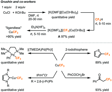 | ||
| Fig. 10 Direct cupration of fluoroform to form CuCF3 for trifluoromethylation reactions.24–26 | ||
Two years after the first report of fluoroform cupration under batch conditions, the same group established a continuous flow process to scale up the synthesis of the CuCF3 reagent.27 In the original report, the cupration step with fluoroform was performed in a Fisher–Porter tube equipped with a pressure gauge, where several fluoroform gas refilling cycles have to be carried out at pressures of up to 50 psi. The cupration step was transferred to flow and the flow setup is depicted in Fig. 11A. The cuprating reagent [K(DMF)n][Cu(Ot-Bu)2] was prepared separately in DMF and delivered into the flow system by a syringe pump. 1.5 equivalents of fluoroform was accurately introduced by an MFC to a Y-mixer and mixed with the cuprating reagent. The resulting gas–liquid segmented flow passed through a PTFE coil at room temperature and atmospheric pressure for a tR of 9.3 minutes and was collected in a vessel under argon atmosphere. The stabilizing step was achieved by pumping TREAT-HF solution to the crude mixture in the collecting vessel under continuous stirring and 94% yield of CuCF3 was obtained. Attempts were made to mix the crude mixture with TREAT-HF in a T-mixer but the precipitation of KF eventually clogged the system. Since CuCF3 is only stable for a few days at room temperature and is air-sensitive, the authors examined the possibility of an in-line trifluoromethylation to consume the trifluoromethylation reagent immediately. Four configurations were tested for trifluoromethylations of α-bromoketone, aryl iodide, bromide, and boronic acids. A representative example is illustrated in Fig. 11B. A peristaltic pump continuously transferred the resultant reagent solution from the original flow setup to a glass reactor where the substrate and additional TREAT-HF solution were continuously introduced. The product yields for these transformations were comparable to the ones obtained from batch production.24–26
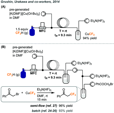 | ||
| Fig. 11 (A) Continuous flow system for preparation of CuCF3 using fluoroform gas. (B) Telescoped system for trifluoromethylation of α-bromoketone.27 | ||
2.2. Difluoromethylations
Fluoroform could be utilized as a source of the CF2H moiety, which has been increasingly present in important pharmaceutical compounds. As previously mentioned, trifluoromethyl anion could rapidly undergo α-elimination of fluoride ions to afford difluorocarbenes. Commercial trifluoromethylation reagents such as TMSCF3 have been shown to generate difluorocarbenes for difluoromethylations,28 difluorocyclopropanations with alkenes,29 and even in situ dimerization to form tetrafluoroethylene gas for tetrafluoroethylation.30 In a recent report, Thomoson and Dolbier demonstrated the first use of fluoroform gas in the direct difluoromethylation of phenols and thiophenols (Fig. 12).31 With continuous bubbling of excess fluoroform gas (8 to 14.2 equiv.) into a mixture of substrate and KOH for 2 to 4 hours, aryl and heteroaryl products were obtained in good-to-excellent yields. Their proposed mechanism involved a nucleophilic attack of the substrate anion to the short-lived electrophilic singlet difluorocarbene generated from fluoroform. When the reaction was carried out using potassium metal as the base and in the presence of D2O, a mixture of deuterated and regular products was provided, indicating that an ArOCF2− intermediate existed and was partly quenched by D2O.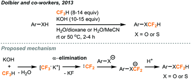 | ||
| Fig. 12 Difluoromethylation of phenols and thiophenols using fluoroform.31 | ||
In addition to the difluorocarbene chemistry, Mikami has proposed, in his difluoromethylation of enolates and nitriles,32,33 lithium-mediated pathways based on their observations and DFT calculations. In the case of enolates (Fig. 13),32 two equivalents of LHMDS (lithium hexamethyldisilazide) led to the aggregation of the lithium enolate homodimer B and the lithium ion was postulated to facilitate a SN2-type C–F activation of fluoroform through Li–F interaction. Carbonyl compounds including ketone, ester, malonate, lactone and lactam were successfully difluoromethylated. For the α-difluoromethylation of aliphatic nitriles (Fig. 14),33 trifluoromethyl lithium and lithium ketene imine were formed in the presence of n-butyl lithium while Li–F interactions were proposed in the transition state C. Removal of lithium fluoride yields the difluoromethyl lithium species D which then abstracts a proton from a fluoroform molecule to give the difluoromethylated product.
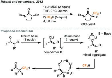 | ||
| Fig. 13 Direct difluoromethylation of lithium enolate using fluoroform.32 | ||
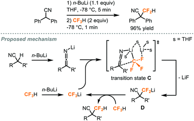 | ||
| Fig. 14 α-Difluoromethylation of nitriles using fluoroform.33 | ||
In 2017, Kappe and co-workers demonstrated the versatility of flow chemistry by 3D-printing a stainless-steel reactor to carry out a continuous flow difluoromethylation of diphenylacetonitrile using fluoroform (Fig. 15).34 The team first designed the reactor model in silico, and tested the hypothetical 3D model using computational fluid dynamics (CDF) simulations to optimize the mixing geometry. The reactor was then printed using a technique called Selective Laser Melting (SLM), in which the metal slices are printed layer-by-layer via fusion of the applied metal powder. The SLM process was shown to reliably reproduce channels of as narrow as 0.6 mm diameter from their 3D model. The Mikami conditions were adopted in this continuous flow difluoromethylation of nitriles (Fig. 15). The substrate and n-BuLi were first mixed for a residence time of about 50 seconds and the resulting mixture was combined with the fluoroform gas introduced by an MFC. The zig-zag nature of the channels could improve mixing by stretching and folding of the flowing stream.35 A cryostat-cooled ethanol solution of −65 °C flowed through the inner tube and the pressure of the system was regulated at 5 bar by a BPR. The authors attempted the same reaction conditions with Teflon tubing and confirmed that the gaseous reagent completely dissolved in the liquid phase. A stream of MeOH quenched the n-BuLi prior to product collection and the difluoromethylated nitrile product was synthesized in 81% yield in less than 2 minutes. Compared to Mikami's method, Kappe's system is fully continuous, safer, easier to operate, and has a high productivity (4.8 vs. 19.5 mmol h−1). Instead of a Li-mediated mechanism, the Kappe group proposed that difluorocarbenes were generated and reacted with the substrate anions.
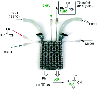 | ||
| Fig. 15 A-3D-printed flow reactor for difluoromethylation of diphenylacetonitrile using fluoroform.34 Reprinted with permission from ref. 34, Copyright 2017 The Royal Society of Chemistry. | ||
The same group also reported direct difluoromethylation on α-sp3-carbon of esters and malonates using the fluoroform gas in continuous flow.36 Mikami's reaction conditions for α-difluoromethylation of carbonyl compounds (LHMDS, THF) were found to be promising in Kappe's flow protocol during optimization studies. The first PFA reactor coil in the continuous flow system (Fig. 16) was employed to deprotonate the substrate at −30 °C for a residence time of 4 minutes. Fluoroform (3 equiv.) was introduced into the system by an MFC and the second coil performed the generation of difluorocarbenes. The authors noted that a pressure of about 5 bar (72.5 psi) and temperatures below 25 C could lead to complete dissolution of fluoroform gas, but the combination of 12 bar (174 psi) pressure and −15 °C at the second reactor coil provided the best conversion and selectivity. The excess use of fluoroform was to prevent pressure fluctuation due to the accumulation of inorganic solids, mainly LiF, inside the BPR. After a room-temperature reaction in the third coil, the desired products were obtained in mostly excellent yields, except for substrates with a sterically hindered phenyl ring at the α-carbon. Notably, the flow difluoromethylation has a significantly shorter reaction time than Mikami's batch protocol as shown by product E (20 min. vs. 20 h).32,36 Since α-difluoromethyl amino acids are potent inhibitors of their corresponding α-amino acid decarboxylases, the α-difluoromethylation of N-benzylidene-protected amino acid methyl esters was also demonstrated and excellent conversions (>95%) were observed. The crude mixtures were then subjected to heating with 6 N HCl at 150 °C in a microwave batch autoclave for 45 minutes to give the unprotected α-CF2H amino acids in 76–87% yield.
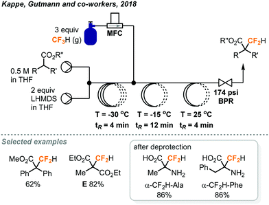 | ||
| Fig. 16 Continuous flow difluoromethylation of α-sp3-carbon centers using fluoroform.36 | ||
In 2018, the Kappe group built on the success of their flow synthesis of α-difluoromethyl-amino acids and developed a scalable continuous flow system for synthesis of D,L-α-difluoromethylornithine (eflornithine) from fluoroform (Fig. 17).37 Eflornithine is used in treatments of bacterial and parasitic infections and has potential anti-cancer activity as well. The previously encountered accumulation of inorganic solids inside the BPR was solved by using a BPR with a wider channel width and smaller dead volume, allowing a smooth flow and the amount of fluoroform used to decrease. A borosilicate static glass mixer plate replaced the second reactor in the previous system (Fig. 16) to further improve mixing while an acidic hydrolysis module was established and coupled to the system. Notably, the PFA tube used (1/8 in. o.d.; 0.8 mm i.d.) for the deprotection process was carefully evaluated to ensure it withstands the high temperature and high pressure applied. Stainless-steel reactor was usually used for high-temperature processes, but was not preferred here due to the corrosion by HCl. After a total residence time of about 23 minutes, ornithine methyl ester F was difluoromethylated and deprotected to give eflornithine hydrochloride monohydrate in 86% isolated yield (19.5 g, 24 mmol h−1). Moreover, only 1.05 equiv. of fluoroform was used and it was fully consumed as determined by 19F NMR analysis.
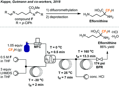 | ||
| Fig. 17 Streamlined system for continuous flow synthesis of eflornithine from fluoroform.37 | ||
3. Trifluoroiodomethane
The odorless and colorless trifluoroiodomethane gas (CF3I, b.p. = −22.5 °C) is an attractive source of the trifluoromethyl fragment due to its low acute inhalation toxicity and availability. It is mainly used as a fire suppression flooding agent and is potentially a very effective greenhouse gas due to the absorption by C–F bonds in the atmospheric window. In the past decade, a vast number of photochemical methods have been developed as a means to release the CF3 radical from CF3I.The pioneering studies by the MacMillan group have allowed for an uptake in usage of CF3I in the synthesis of small molecules. In the 2000s, they have demonstrated the use of a unique combination of enamine and organometallic photoredox catalysis to activate the relatively inert CF3I (Fig. 18).38 CF3 radicals were produced and subsequently used in the synthesis of enatiotopically enriched α-trifluoromethyl aldehydes. Using (2R,5S)-2-t-butyl-3,5-dimethylimidazolidin-4-one TFA in 20 mol% as the chiral amine catalyst, Ir(ppy)2(dtb-bpy)PF6 as the photocatalyst, and 2,6-lutidine as an ancillary base, a variety of aldehydes could react with CF3I to produce the α-trifluoromethylated aldehydes with high enantiopurity (Fig. 18). In their protocol, the CF3I (8.1 equiv.) was condensed in the reaction medium using a cold finger and a needle. Reactions required a temperature of −20 °C to retain the enantioselectivity. These conditions also allowed for the substitution of CF3I with an array of other fluorinated alkyl iodides.
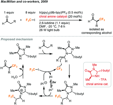 | ||
| Fig. 18 Enantioselective α-trifluoromethylation of aldehyde using trifluoroiodomethane.38 | ||
For the proposed mechanism in Fig. 18, the excited iridium catalyst removes an electron from excess imidazolidinone and transfers it to the CF3I via a single electron transfer (SET) mechanism to generate the trifluoromethyl radical. This radical species then reacts with the enamine formed from the condensation of the imidazolidinone and the aldehyde. Chirality is induced here by the tert-butyl and methyl substituents of the imidazolidinone. The sterically hindering tert-butyl group will direct the alkene moiety away from itself and the methyl group selectively blocks radical addition to the Re face of the molecule, promoting Si facial selectivity. The resulting radical species is then converted into an iminium ion by the photocatalyst to perpetuate the photoredox cycle. The iminium ion is converted into the product aldehyde by hydrolysis.
A more general method was later developed by MacMillan and co-workers to use silyl enol ethers in the synthesis of racemic α-trifluoromethyl ketones (Fig. 19).39 This methodology was extended to esters and amides as well, without the need for a photocatalyst.
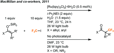 | ||
| Fig. 19 Synthesis of α-trifluoromethylated ketones, amides and esters.39 | ||
The Sanford group has built on MacMillan's work to utilize CF3I in the synthesis of aryl trifluoromethane products (Fig. 20).12 Trifluoromethylated arenes are a common substructure of many medicinally relevant compounds. Sandford and co-workers demonstrated the trifluoromethylation of aryl boronic acids with CF3I gas via the merger of photoredox and copper catalysis. Aryl-CF3 cross-coupling is accomplished by reacting aryl boronic acids with CF3I, using 20 mol% copper(I)acetate and 1 mol% Ru(bpy)3Cl2·6H2O catalysts under irradiation of two 26W fluorescent lightbulbs. Stock solutions of CF3I (0.25 M) were prepared by bubbling the gas into DMF (Fig. 2A). A variety of (hetero)aryl boronic acids could be accommodated with electron withdrawing and electron donating substituents. Yields suffered when sterically hindered boronic acid substrates were used and low amounts of aryl iodide side products were occasionally observed.
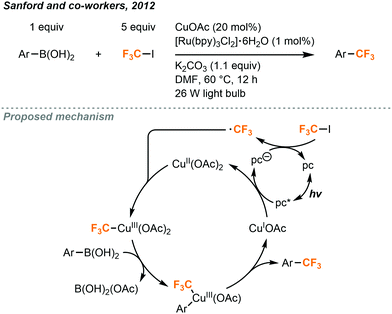 | ||
| Fig. 20 Cu/Ru-catalyzed trifluoromethylation of boronic acids.12 | ||
A proposed mechanism (Fig. 20) suggests that photoexcited Ru(bpy)3Cl2·6H2O oxidizes the copper(I) catalyst to copper(II) and transfers that electron to CF3I to generate the trifluoromethyl radical. The radical species can then combine with the copper catalyst to generate a copper(III) intermediate which undergoes transmetalation with the boronic acid substrate and subsequent reductive elimination to form the C–C bond in the product, followed by a regeneration of the copper(I) catalyst.
Further advancements that improve the accessibility of CF3I gas have been made. Ritter and co-workers have developed stable stock solutions of CF3I in tetramethylguanidine (TMG) and dimethyl sulfoxide (DMSO).40 By taking advantage of halogen bonding, CF3I can be bubbled into solution to make 1![[thin space (1/6-em)]](https://www.rsc.org/images/entities/char_2009.gif) :
:![[thin space (1/6-em)]](https://www.rsc.org/images/entities/char_2009.gif) 1 or 1
1 or 1![[thin space (1/6-em)]](https://www.rsc.org/images/entities/char_2009.gif) :
:![[thin space (1/6-em)]](https://www.rsc.org/images/entities/char_2009.gif) 2 adducts with TMG and DMSO respectively. These liquid reagents are comparatively easier to handle, measure and reliably maintain the concentration of CF3I over a period of at least two months when stored at 0 °C. These reagents are useful in a variety of trifluoromethylation reactions as demonstrated by the Ritter group. A procedure for trifluoromethylation of arenes via copper catalyzed C–H activation was optimized and used to produced and impressive scope of aryl trifluoromethanes using the TMG·CF3I reagent. Examples of other transformations such as olefin and thiol trifluoromethylations, α-trifluoromethylation of silyl enol ethers, and trifluoromethyl addition to aldehydes could all be carried out using these stock solutions to generate products in competitive yields compared to the counterpart reaction using CF3I gas. Solutions of CF3I in TMG or DMSO, as well as the analogous C2F5I solutions, are currently commercially available or can be prepared using a Schlenk line manifold. However, it should be noted that DMSO is a potential ligand for transition metal such as palladium. For example, using the CH3I complex solution in transition metal-catalyzed reactions could be difficult because the DMSO might be competitive with the ancillary ligands and might affect the efficiency of the reactions.
2 adducts with TMG and DMSO respectively. These liquid reagents are comparatively easier to handle, measure and reliably maintain the concentration of CF3I over a period of at least two months when stored at 0 °C. These reagents are useful in a variety of trifluoromethylation reactions as demonstrated by the Ritter group. A procedure for trifluoromethylation of arenes via copper catalyzed C–H activation was optimized and used to produced and impressive scope of aryl trifluoromethanes using the TMG·CF3I reagent. Examples of other transformations such as olefin and thiol trifluoromethylations, α-trifluoromethylation of silyl enol ethers, and trifluoromethyl addition to aldehydes could all be carried out using these stock solutions to generate products in competitive yields compared to the counterpart reaction using CF3I gas. Solutions of CF3I in TMG or DMSO, as well as the analogous C2F5I solutions, are currently commercially available or can be prepared using a Schlenk line manifold. However, it should be noted that DMSO is a potential ligand for transition metal such as palladium. For example, using the CH3I complex solution in transition metal-catalyzed reactions could be difficult because the DMSO might be competitive with the ancillary ligands and might affect the efficiency of the reactions.
These CF3I stock solution reagents will likely support future research on new transformations using this synthetic building block. One such example is the construction of trifluoromethylated cyclobutyl rings using DMSO·CF3I by the Aggarwal group.41 Photochemically generated trifluoromethyl radical can react with the strained Sigma bond in a bicyclo[1.1.0]butane (BCB)-boronate complex, which in turn is formed from reaction with a sulfoxide bearing the bicyclo[1.1.0]butane group and a boronate ester bearing the desired organic group (Fig. 21). This reaction yielded trifluoromethylated cyclobutyl rings bearing a boron ester and a variety of organic groups on the newly formed quaternary carbon with high diastereoselectivity. The method is compatible with many biologically relevant molecules and can be extended to a wide scope of other electron poor fluoroalkyl iodides beyond CF3I. The sulfoxide and boronate ester were first reacted with lithium tert-butoxide at −78 °C for 15 minutes. Addition of the DMSO·CF3I and irradiation with blue LED lights for 1 hour yielded the final trifluoromethylated product. Mechanistic investigations suggested that the blue light promotes homolysis of the CF3I to generate the trifluoromethyl radical which attacks the strained Sigma bond of the (BCB)–boronate complex. The resulting radical species can then pass an electron to another molecule of CF3I propagating the chain reaction, leaving the now electron-deficient species to undergo a fast 1,2-metalate rearrangement to yield the product.
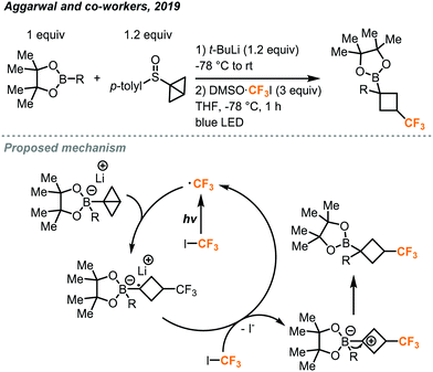 | ||
| Fig. 21 Synthesis of cyclobutyl boronic esters bearing the trifluoromethyl group.41 | ||
While photocatalysis has greatly increased the utility of CF3I gas, it can still be difficult to handle and accurately measure concentrations. Continuous flow chemistry can provide an alternative which allows accurate measurements, controlled delivery of CF3I via mass flow controllers, and superior gas–liquid mixing compared to batch experiments.
In 2014, the Noel and Hessel groups have collaboratively utilized CF3I gas in continuous flow to produce several classes of valuable trifluoromethylated products.42 Trifluoromethylation of five-membered heteroaryl rings was possible using 1–4 mol% of [Ru(bpy)3Cl2] photocatalyst and TMEDA base (tetramethylethylenediamine) in acetonitrile under continuous flow conditions. Mass flow controllers accurately delivered 4 equivalents of CF3I gas under optimal conditions (Fig. 22), which could be varied to accommodate different substrates. The use of transparent PFA tubing allowed homogeneous photo-irradiation of the reaction mixture, whereas this is a challenge in scaling up batch photochemical reactions due to absorption and limited penetration depth of light. The microreactor was placed in a beaker with blue light-emitting diode (LED) light strip coiled inside. After a residence time of 8 to 32 minutes, a variety of heteroarenes including pyrroles, indoles, furans and thiophenes, were trifluoromethylated in 55 to 95% yields. In this flow system, a BPR was not used and a Taylor flow regime resulted for gas–liquid mixing. The benefits of continuous flow conditions and the microreactor technology for this photochemical transformation, such as ease of scalability and catalyst loading optimization, were demonstrated. In less than 9 hours, a long durational flow reaction produced 1.98 g (9.5 mmol) of product G. It was possible to lower the catalyst loading to 0.05 mol% by extending the residence time to 32 minutes.
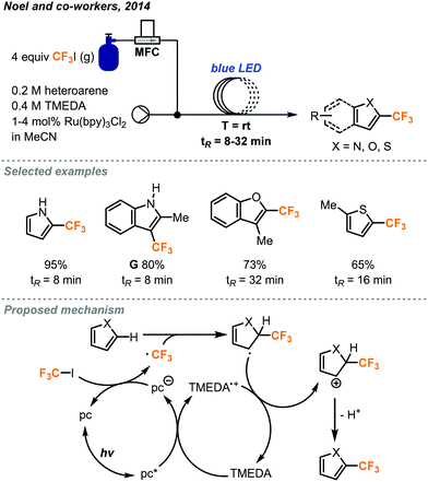 | ||
| Fig. 22 Trifluoromethylation of five-membered heterocycles via photocatalysis in continuous flow.42 | ||
The mechanism of this transformation was further investigated in another report.43 The use of microreactor technology allowed for the precise determination of photon flux, quantum yield and reaction rate constants to help elucidate the mechanism. The consumption of CF3I gas in the Taylor flow regime directly changed the residence time of the reaction mixture in the flow reactor coil, and the residence time was used as a key factor in kinetic studies. As outlined in Fig. 22, the excited photocatalyst follows a reductive pathway, whereby it is first reduced by the TMEDA and passes this electron onto CF3I as supported by Stern–Volmer experiments. Once the trifluoromethyl radical attacks the heterocycle and forms a radical intermediate, this new radical species then donates an electron to TMEDA and undergoes elimination to produce the product and complete the cycle.
Incorporation of S-CF3 groups into biologically active molecules is a growing area of research. Methods to synthesize aryl and alkyl S-CF3 compounds have been developed by Wang, Noel and co-workers using batch and continuous flow protocols with a similar photocatalytic system and conditions as discussed above (Fig. 23).44 It was found that the rate of the batch reaction was dependent on the amount of mixing. By carrying out the reaction in continuous flow, a greater interfacial area between gas and liquid reagents was achieved, allowing for an acceleration of the reaction and significantly shortened reaction time. With a residence time of just 1 minute, it was possible to obtain trifluoromethylated products from (hetero)aryl and alkyl thiols in competitive or better yields compared with those of the batch protocol. The amount of CF3I gas required could also be reduced to from 4 to 1.1 equivalents by utilizing continuous flow conditions.
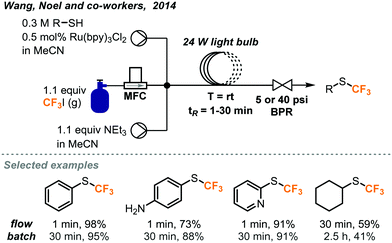 | ||
| Fig. 23 Photocatalyzed trifluoromethylation of thiols in continuous flow.44 | ||
In a separate report, Noel and co-workers investigated trifluoromethylations of cysteine residues (Fig. 24).45 This class of thiols are particularly interesting since the trifluoromethylated derivatives may find use in a variety of peptide labeling applications. This trifluoromethylation of sulfur atoms for batch and continuous flow were also developed using Ru(bpy)3Cl2 as the photocatalyst. Reactions performed in continuous flow were found to have increased efficiency and resulted in 10% more formation of product on average compared to the batch reactions. The reaction time was decreased from 2 hours in batch to 5 minutes (tR) in continuous flow.
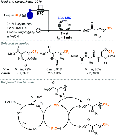 | ||
| Fig. 24 Photocatalyzed trifluoromethylation of cysteine residues in continuous flow.45 | ||
The active trifluoromethyl radical is proposed to be generated via photoexcitation of the photocatalyst followed by reductive quenching allowing to the reduced catalyst to transfer an electron to the CF3I gas. The trifluoromethyl radical then reacts with the thiol substrate to generate a trifluoromethylated thiol radical. Mechanistic investigations find evidence to support the presence of a chain propagating SET step where the thiol radical species transfers an electron to another molecule of CF3I to continue the reaction and generate the desired product (Fig. 24).
In 2016, conditions were reported by Noel and co-workers for the trifluoromethylation and hydrotrifluoromethylation of styrenes.46 These trifluoromethyl-containing products are useful in both pharmaceutical and materials synthesis due to the altered properties relative to their non-fluorinated counterparts. Although Ru(bpy)3Cl2 was found to be a competent photocatalyst for many of the above transformations using CF3I, it was unable to provide satisfactory yields in the trifluoromethylation of styrenes. Suitable reaction conditions were found using fac-Ir(bpy)3 as the photocatalyst in 0.5 mol% (Fig. 25), and trans-isomers of the products were primarily provided. Batch conditions for the transformation were also developed, but increased selectivity for the trans-isomers were observed in continuous flow. The trans-selectivity in continuous flow for this transformation was postulated to be due to the homogenous irradiation of the reaction medium and shorter irradiation period for the product molecules. The shortened irradiation time in flow resulted in the suppression of isomerization from trans- to cis-isomer via an energy transfer mechanism. In addition to trifluoromethylated styrenes, hydrotrifluoromethylated styrenes could also be produced by addition of 4-hydroxythiophenol (4-HTP) as a hydrogen atom donor and changing the reaction solvent (Fig. 25). The modularity to generate trifluoromethylated or hydrotrifluoromethylated styrene products accompanied by the ability to easily substitute other electron poor alkyl iodides to perform perfluoroalkyl reactions gives this methodology a clear advantage over other olefin trifluoromethylation procedures. The continuous flow setups for both transformations were similar to those depicted in Fig. 23 and 24, where the syringe stored the substrates and catalysts, and the MFC delivered the gaseous CF3I into the system.
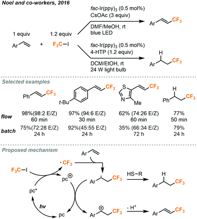 | ||
| Fig. 25 Photocatalytic trifluoromethylation and hydrotrifluoromethylation of styrenes in continuous flow.46 | ||
The proposed mechanism for both transformations is shown in Fig. 25. The iridium photocatalyst is first excited and transfers an electron to CF3I to produce the trifluoromethyl radical which can react with the styrene substrate. In the pathway leading to trifluoromethylation, the resulting radical species is then oxidized by the photocatalyst to form a carbocation intermediate to complete the photocatalytic cycle. Solvent adducts have been observed by GC-MS (gas chromatography–mass spectrometry) to support the hypothesis that the radical and carbocation intermediates are stabilized by solvation. The carbocation then undergoes elimination to provide the product. In the hydrotrifluoromethylation pathway, the radical species instead reacts with the hydrogen atom donor to form the alkyl product. Radical thiol then donates an electron to the photocatalyst to close the cycle.
4. Chlorodifluoromethane
Chlorodifluoromethane (ClCF2H, as known as Freon 22 and HCFC-22) is a colorless gas and a potent ozone-depleting substance with a boiling point of −41 °C. It is a relatively cheap industrial chemical used to produce fluoropolymers and was widely used as a refrigerant. Under the Montreal Protocol, it has been mostly phased out for servicing refrigeration and air-conditioning equipment in developed countries. However, exemptions were given for analytical, research and development purposes, including its use as a reaction feedstock.47 It is worth mentioning that ClCF2H, albeit being an attractive CF2 source, has a GWP equal to 1810 and raises additional environmental concerns when used in organic synthesis. Like fluoroform, deprotonation of the ClCF2H gas generates a chlorodifluoromethyl anion which rapidly undergoes α-elimination to give singlet difluorocarbenes which can be used in difluoromethylation reactions.In 2017, the Kappe group disclosed the use of ClCF2H in the continuous flow synthesis of a key pharmaceutical intermediate I (Fig. 26) towards the preparation of eflornithine.48 The difluoromethylated malonate I bearing a nitrile group was prepared from commercially available malonate H, ClCF2H and easily accessible reagents under basic conditions. Upon reaction with bases such as NaOH or KOH, the ClCF2H can eliminate HCl to yield an electrophilic difluorocarbene, which then reacts with the anion of malonate H to give the difluoromethylated product. During optimization under batch conditions, the reactions gave moderate to good yields, but had poor selectivity and reproducibility. Further optimization of the transformation was then carried out in continuous flow. To prevent clogging caused by accumulation of inorganic solids (NaCl, KCl) as a result of α-elimination, a biphasic reaction medium using MeCN and aqueous NaOH was used to keep all components dissolved throughout the reaction. A microreactor plate with microstructures fabricated into the channels was used to increase mixing of the two immiscible phases. The organic phase containing the malonate and ClCF2H (condensed in MeCN) were injected into the microreactor in one stream and the basic aqueous phase was injected in a second stream. The use of a BPR (5 bar, 72.5 psi) enabled elevated temperatures up to 107 °C and kept the gas in solution. By harnessing the increased mixing and heat transfer of continuous flow, the rate of the productive reaction could be increased and allowed shorter reaction time to decrease the decomposition of ClCF2H. Optimal conditions were found to be 2.5 equivalents of ClCF2H, a concentration of 0.78 M of the malonate in MeCN for the organic phase and 8 M NaOH as the aqueous phase. The desired difluoromethylated product was obtained in 73% yield after a residence time of 24 minutes and the organic phase has a consistent high purity of 95% as determined by GC-FID (gas chromatography with flame-ionization detection).
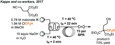 | ||
| Fig. 26 Telescoped continuous flow synthesis of key intermediate I towards the synthesis of eflornithine.48 | ||
Another procedure utilizing ClCF2H gas to form value-added products was reported by Fu and Jamison in the continuous flow synthesis of α-CF2D benzyl alcohols and gem-difluoroalkenes from aldehydes.49 Most previous methods used to form these products are considerably less atom economical than ClCF2H gas for the installation of the CF2H moiety.10 As mentioned previously, CF2H groups are becoming more prominent in pharmaceuticals and other important compounds. Using this new procedure, CF2H groups can be installed efficiently as can the deuterated version (CF2D) which has been much less explored. As depicted in Fig. 27, the difluorocarbene is formed in solution through deprotonation of ClCF2H by LiOt-Bu followed by α-elimination of the chloride. The difluorocarbene can then react with triphenylphosphine to generate a phosphorus ylide. This ylide intermediate can then interact with the aldehyde substrate to form a difluoromethylated oxaphosphetane intermediate as shown in Fig. 27. NMR study suggests that it is at this stage that the phosphorus atom of the oxaphosphetane is more electrophilic than usual due to the electron-withdrawing CF2 group, and can be hydrolyzed to give the α-CF2D benzyl alcohols and triphenylphosphine oxide. Alternatively, the oxaphosphetane can eliminate the triphenylphosphine oxide and gem-difluoroalkene product via a retro [2+2] cycloaddition under sufficient heating (100 °C). The ability of in-line generation and immediate consumption of an unstable species (oxaphosphetane), and the precise temperature control is highly advantageous and critical. Optimal conditions require three streams of reagents: the aldehyde substrate and triphenylphosphine in THF (2.0 equiv.), LiOt-Bu in THF (2.0 equiv.), and the ClCF2H gas (3.0 equiv., 1.32 sccm) (Fig. 28). These streams are mixed in a coil at 0 °C with a residence time of 11.9 minutes. At this point, the oxaphosphetane is formed and can either exit through a BPR (50 psi), introduced into a stream of water or D2O and reacted in a room temperature coil (tR = 3 min) or directly carried through to a heated coil (100 °C, tR = 4 min) depending on the desired product. Both procedures demonstrated a wide scope of reactivity and tolerance of many functional groups including hereroaryls, aryl halides, trifluoromethanes, ethers and vinyl halides. Both methods could be used for the production of derivatives of pharmaceutical compounds (adapalene, ataluren and probenecid). Advantages of continuous flow chemistry are also showcased here by the ability to use the ClCF2H gas directly with an MFC and super heat solvents to achieve optimal yields. In this work, only LiOt-Bu could be successfully used due to the generation of a soluble LiCl salt after α-elimination. Using KO-tBu or NaOt-Bu quickly generated insoluble inorganic salts, which clogged the tubings.
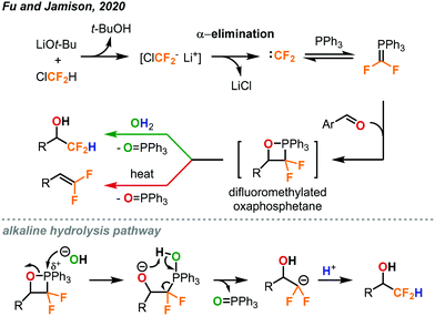 | ||
| Fig. 27 Formation of difluoromethylated oxaphosphetene as a key intermediate towards the synthesis of α-CF2D benzyl alcohols and gem-difluoroalkenes.49 | ||
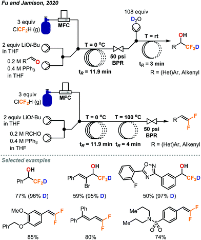 | ||
| Fig. 28 Continuous flow deuteriodifluoromethylation and gem-difluoroalkenylation of aldehydes using chlorodifluoromethane gas.49 | ||
The gem-difluoroalkenylation of aldehydes using ClCF2H gas under batch conditions was reported by Xiao in 2013 (Fig. 29).50 In their protocol, the ClCF2H gas was saturated in DMF to make a stock solution and a sealed tube was used for the reaction. To avoid the rapid generation of difluorocarbenes by using strong bases, an epoxide ring-opening approach was used to afford a low concentration of alkoxide anion for prolonged deprotonation of ClCF2H. n-BuNCl4 was used in catalytic amount, and the 4 Å molecular sieve was both a drying agent and a Lewis acid to promote ring-opening of epoxide. A series of gem-difluoroalkenes was prepared in 49–92% yield after a 6 hour reaction at 110 °C.
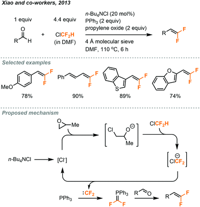 | ||
| Fig. 29 gem-Difluoroalkenylation of aldehydes using chlorodifluoromethane under batch conditions.50 | ||
5. Conclusion and outlook
The use of fluorinated greenhouse gases in fluoroalkylations has been made scalable, continuous, more efficient, environmentally friendly, safer, and easier to operate through translation to a continuous flow setting. We created this tutorial review article to highlight examples that would inspire chemists to exploit the ability of flow chemistry. Emphases have been given on the reactions’ batch-to-flow transitions, experimental techniques used and some of our insights under flow-enabled conditions. Although flow chemistry, especially regarding gas–liquid reactions, is usually used to optimize batch protocols by increasing control of reaction parameters or telescoping of multiple separate synthetic steps, we have shown some of the examples in this review article that flow techniques can indeed enable previously improbable reaction conditions. For example, the accurate delivery of gases by a mass flow controller and the small-scale generation–consumption of an unstable oxaphosphetane species led to the observation of new phosphorus chemistry and facile preparation of rare deuteriodifluoromethylated products. The in-line analysis techniques described in this review should be highly advantageous for discovery of new reaction mechanisms and could open up new chemical spaces. In particular, photochemical reactions using gases could benefit massively from flow technologies because of the limited mixing and penetration depth of irradiation under batch conditions, which caused longer reaction times, higher catalyst loadings or poor scalability. Finally, we envisioned that eventually many of the continuous flow systems created to transform the fluorinated greenhouse gases to value-added chemicals could be incorporated into greenhouse gas recycling facilities or waste management facilities in the fluorinated polymer production lines. Owing to the many unique advantages of flow chemistry including small system footprint, high reproducibility, scalability, system automations, improved safety, lowered cost and waste generation, we believe the continuous flow approaches will be highly applicable and feasible in industrial settings.Conflicts of interest
There are no conflicts to declare.Acknowledgements
This work was supported by the Croucher Foundation (Hong Kong), the Natural Sciences and Engineering Research Council of Canada (NSERC), and the Defense Advanced Research Project Agency (DARPA) under contract number ARO W911NF-16-2-0023.Notes and references
- R. Berger, G. Resnati, P. Metrangolo, E. Weber and J. Hulliger, Chem. Soc. Rev., 2011, 40, 3496 RSC.
- L. Xing, D. C. Blakemore, A. Narayanan, R. Unwalla, F. Lovering, R. A. Denny, H. Zhou and M. E. Bunnage, ChemMedChem, 2015, 10, 715 CrossRef CAS PubMed.
- E. P. Gillis, K. J. Eastman, M. D. Hill, D. J. Donnelly and N. A. Meanwell, J. Med. Chem., 2015, 58, 8315 CrossRef CAS.
- Y. Zhuo, J. Wang, Z. Gu, S. Wang, W. Zhu, J. L. Acena, V. A. Soloshonok, K. Izawa and H. Liu, Chem. Rev., 2016, 116, 422 CrossRef.
- N. A. Meanwell, J. Med. Chem., 2018, 61, 5822 CrossRef CAS PubMed.
- Y. Zafrani, G. Sod-Moriah, D. Yeffet, A. Berliner, D. Amir, D. Marciano, S. Elias, S. Katalan, N. Ashkenazi, M. Madmon, E. Gershonov and S. Saphier, J. Am. Chem. Soc., 2019, 62, 5628 CAS.
- S. Barata-Vallejo, B. Lantaño and A. Postigo, Chem. – Eur. J., 2014, 20, 16806 CrossRef CAS PubMed.
- J. Charpentier, N. Früh and A. Togni, Chem. Rev., 2015, 2, 650 CrossRef PubMed.
- X. Pan, H. Xia and J. Wu, Org. Chem. Front., 2016, 3, 1163 RSC.
- D. E. Yerien, S. Barata-Vallejo and A. Postigo, Chem. – Eur. J., 2017, 23, 14676 CrossRef CAS PubMed.
- G.-b. Li, C. Zhang, C. Song and Y.-d. Ma, Beilstein J. Org. Chem., 2018, 14, 155 CrossRef CAS PubMed.
- Y. Ye and M. S. Sanford, J. Am. Chem. Soc., 2012, 134, 9034 CrossRef CAS PubMed.
- M. Brzozowski, M. O’Brien, S. V. Ley and A. Polyzos, Acc. Chem. Res., 2015, 48, 349 CrossRef CAS PubMed.
- C. J. Mallia and I. R. Baxendale, Org. Process Res. Dev., 2016, 20, 327 CrossRef CAS.
- M. B. Plutschack, B. Pieber, K. Gilmore and P. H. Seeberger, Chem. Rev., 2017, 117, 11796 CrossRef CAS PubMed.
- C. A. Hone and C. O. Kappe, Top. Curr. Chem., 2019, 377, 2 CrossRef PubMed.
- P. Angeli and A. Gavriilidis, in Taylor Flow in Microchannels. In Encyclopedia of Micro fluidics and Nano fluidics, ed. D. Li, Springer, Boston, MA, 2008, pp. 1971–1976 Search PubMed.
- P. Forster, V. Ramaswamy, P. Artaxo, T. Berntsen, R. Betts, D. W. Fahey, J. Haywood, J. Lean, D. C. Lowe, G. Myhre, J. Nganga, R. Prinn, G. Raga, M. Schulz and R. Van Dorland, in Changes in atmospheric constituents and in radiative forcing. In Climate change 2007: The Physical Science Base, Fourth Assessment Report of the Intergovernmental Panel on Climate Change, ed. S. Soloman, D. Qin, M. Manning, Z. Chen, M. Marquis, K. B. Averyt, M. Tignor and H. L. Miller, Cambridge University Press, Cambridge, 2007 Search PubMed.
- E. A. Symons and M. J. Clermont, J. Am. Chem. Soc., 1981, 103, 3127 CrossRef CAS.
- V. V. Grushin, Chim. Oggi – Chem. Today, 2014, 32, 81 CAS.
- G. K. S. Prakash, P. V. Jog, P. T. D. Batamack and G. A. Olah, Science, 2012, 338, 1324 CrossRef CAS PubMed.
- B. Musio, E. Gala and S. V. Ley, ACS Sustainable Chem., 2018, 6, 1489 CrossRef CAS.
- K. Hirano, S. Gondo, N. Punna, E. Tokunaga and N. Shibata, ChemistryOpen, 2019, 8, 406 CrossRef CAS PubMed.
- A. Zanardi, M. A. Novikov, E. Martin, J. Benet-Buchholz and V. V. Grushin, J. Am. Chem. Soc., 2011, 133, 20901 CrossRef CAS PubMed.
- P. Novák, A. Lishchynskyi and V. V. Grushin, J. Am. Chem. Soc., 2012, 134, 16167 CrossRef PubMed.
- A. I. Konovalov, J. Benet-Buchholz, E. Martin and V. V. Grushin, Angew. Chem., Int. Ed., 2013, 52, 11637 CrossRef CAS PubMed.
- Z. Mazloomi, A. Bansode, P. Benaventa, A. Lishchynskyi, A. Urakawa and V. V. Grushin, Org. Process Res. Dev., 2014, 18, 1020 CrossRef CAS.
- Q. Xie, C. Ni, R. Zhang, L. Li, J. Rong and J. Hu, Angew. Chem., Int. Ed., 2017, 56, 3206 CrossRef CAS PubMed.
- F. Wang, T. Luo, J. Hu, Y. Wang, H. S. Krishnan, P. V. Jog, S. K. Ganesh, G. K. S. Prakash and G. A. Olah, Angew. Chem., Int. Ed., 2011, 50, 7153 CrossRef CAS PubMed.
- L. Li, C. Ni, Q. Xie, M. Hu, F. Wang and J. Hu, Angew. Chem., Int. Ed., 2017, 56, 9971 CrossRef CAS PubMed.
- C. S. Thomoson and W. R. Dolbier, Jr., J. Org. Chem., 2013, 78, 8904 CrossRef CAS PubMed.
- T. Iida, R. Hashimoto, K. Aikawa, S. Ito and K. Mikami, Angew. Chem., Int. Ed., 2012, 51, 9535 CrossRef CAS PubMed.
- K. Aikawa, K. Maruyama, K. Honda and K. Mikami, Org. Lett., 2015, 17, 4882 CrossRef CAS PubMed.
- B. Gutmann, M. Köckinger, G. Glotz, T. Ciaglia, E. Slama, M. Zadravec, S. Pfanner, M. Bersier, H. Gruber-Wölfler and C. O. Kappe, React. Chem. Eng., 2017, 2, 919 RSC.
- R. Reintjens, D. J. Ager and A. H. De Vries, Chim. Oggi, 2015, 33, 21 Search PubMed.
- M. Köckinger, T. Ciaglia, M. Bersier, P. Hanselmann, B. Gutmann and C. O. Kappe, Green Chem., 2018, 20, 108 RSC.
- M. Köckinger, C. A. Hone, B. Gutmann, P. Hanselmann, M. Bersier, A. Torvisco and C. O. Kappe, Org. Process Res. Dev., 2018, 22, 1553 CrossRef.
- D. A. Nagib, M. E. Scott and D. W. C. MacMillan, J. Am. Chem. Soc., 2009, 131, 10875 CrossRef CAS PubMed.
- P. V. Pham, D. A. Nagib, M. E. Scott and D. W. C. MacMillan, Angew. Chem., Int. Ed., 2011, 50, 6119 CrossRef CAS PubMed.
- F. Sladojevich, E. McNeill, J. Bçrgel, S. Zheng and T. Ritter, Angew. Chem., Int. Ed., 2015, 54, 3712 CrossRef CAS PubMed.
- M. Silvi and V. K. Aggarwal, J. Am. Chem. Soc., 2019, 141, 9511 CrossRef CAS PubMed.
- N. J. W. Straathof, H. P. L. Gemoets, X. Wang, J. C. Schouten, V. Hessel and T. Noël, ChemSusChem, 2014, 7, 1612 CrossRef CAS PubMed.
- Y. Su, K. P. L. Kuijpers, N. Kçnig, M. Shang, V. Hessel and T. Noël, Chem. – Eur. J., 2016, 22, 12295 CrossRef CAS PubMed.
- N. J. W. Straathof, B. J. P. Tegelbeckers, V. Hessel, X. Wang and T. Noël, Chem. Sci., 2014, 5, 4768 RSC.
- C. Bottecchia, X. Wei, K. P. L. Kuijpers, V. Hessel and T. Noël, J. Org. Chem., 2016, 81, 7301 CrossRef CAS.
- N. J. W. Straathof, S. E. Cramer, V. Hessel and T. Noël, Angew. Chem., Int. Ed., 2016, 55, 15549 CrossRef CAS PubMed.
- Ozone Secretariat, Handbook for the Montreal Protocol on Substances that Deplete the Ozone Layer, Twelfth edition, United Nations Environment Programme, Nairobi, 2018 Search PubMed.
- B. Gutmann, P. Hanselmann, M. Bersier, D. Roberge and C. O. Kappe, J. Flow Chem., 2017, 7, 46 CrossRef CAS.
- W. C. Fu and T. F. Jamison, Angew. Chem., Int. Ed., 2020, 59, 13885 CrossRef CAS PubMed.
- J. Zheng, J.-H. Lin, J. Cai and J.-C. Xiao, Chem. – Eur. J., 2013, 19, 15261 CrossRef CAS PubMed.
| This journal is © The Royal Society of Chemistry 2021 |


