
 Open Access Article
 This Open Access Article is licensed under a Creative Commons Attribution-Non Commercial 3.0 Unported Licence
Electrodeposition of neodymium and dysprosium from organic electrolytes†
Pieter
Geysens
 a,
Pin-Cheng
Lin
b,
Jan
Fransaer
c and
Koen
Binnemans
*a
a,
Pin-Cheng
Lin
b,
Jan
Fransaer
c and
Koen
Binnemans
*a
aKU Leuven, Department of Chemistry, Celestijnenlaan 200F, P.O. box 2404, B-3001 Leuven, Belgium. E-mail: Koen.Binnemans@kuleuven.be
bKU Leuven, Department of Physics and Astronomy, Celestijnenlaan 200D, B-3001 Leuven, Belgium
cKU Leuven, Department of Materials Engineering, Kasteelpark 44, P.O. box 2450, B-3001 Leuven, Belgium
First published on 6th April 2021
Abstract
A new class of organic electrolytes has been developed for the electrodeposition of rare-earth metals at room temperature. These electrolytes consist of a rare-earth bis(trifluoromethylsulfonyl)imide or chloride salt and a borohydride salt, dissolved in the ether solvents 1,2-dimethoxyethane or 2-methyltetrahydrofuran. In these electrolytes, a soluble lanthanide(III) borohydride complex [Ln(BH4)4]− is formed, which allows for the electrodeposition of neodymium- or dysprosium-containing layers. The electrochemistry of these electrolytes was characterized by cyclic voltammetry. The deposits were characterized by scanning electron microscopy (SEM), energy-dispersive X-ray fluorescence (EDX) and X-ray photoelectron spectroscopy (XPS), and the results suggest the presence of metallic neodymium and dysprosium.
Introduction
Rare-earth elements (REEs) are a group of metals with many unique optical, magnetic and electrical properties. Therefore, they are extensively used in important applications such as lamp phosphors, permanent magnets, rechargeable nickel metal hydride batteries and catalysts.1–3 In the permanent magnets, the REEs are used in their metallic form. Electrodeposition of REEs is challenging due to the very negative standard reduction potentials (around −2.3 V) of these metals. This excludes the use of aqueous electrolytes that have a narrow electrochemical stability window. Currently, molten salt electrolytes are the leading technology for REE electrodeposition, but this process is very energy-intensive due to the high operational temperatures (>500 °C).4–7Recently, ionic liquids (ILs), a low-melting subclass of molten salts, have been investigated as alternative electrolytes for the electrodeposition of REEs at moderate temperatures (70–150 °C).8 The electrodeposition of dysprosium, lanthanum, yttrium, ytterbium, and gadolinium has been reported from ammonium, pyrrolidinium and phosphonium ILs.9–14 However, the electrodeposition of neodymium is much more challenging because it is more reactive than most heavy rare earths, and only limited success was obtained in phosphonium ILs.15–19
Although ILs can be used as low-temperature alternatives for molten salts in the electrowinning of REEs, they also have some considerable drawbacks. Firstly, most of these ILs are based on the bis(trifluoromethylsulfonyl)imide (bistriflimide, Tf2N−) anion, which contains strongly electron-withdrawing trifluoromethylsulfonyl groups, making it prone to react with the reducing metallic REEs.20–22 This leads to the formation of passivating surface films (fluorides) during deposition and results in a loss of current density.23,24 Secondly, bistriflimide salts are synthesized via a multi-step procedure and are only produced on a relatively small scale, mainly for the battery and catalyst markets.25,26 Therefore, bistriflimide salts and the corresponding ionic liquids are expensive, which makes these ionic liquids less suitable for large-scale applications such as electrowinning. Thirdly, the environmental impact of bistriflimide is considerable because it is strongly fluorinated and thus persistent in the environment.27
Hence, there is a growing interest to find alternative electrolytes that allow for electrodeposition of REEs at ambient of slightly elevated temperature, while also avoiding or limiting the use of bistriflimide-based ILs or salts. ILs with the dicyanamide anion (DCA−) have many favorable properties for the electrodeposition of metals.28 The DCA− anion is one of the few anions that combines a highly delocalized negative charge with strong coordinating abilities toward metal ions. Therefore DCA-based ILs have a very low viscosity, while also allowing high solubilities for metal salts, resulting in good mass-transport properties during electrodeposition. DCA-based ILs are promising electrolytes for the electrodeposition of various transition metals (Ni, Zn, Mn).28 The electrodeposition of a Fe–Dy alloy was also recently reported.29 However, the electrochemical stability of DCA-based ILs is too low to support the electrodeposition of pure REEs.30,31 ILs with trifluoromethanesulfonate (triflate) anions have been explored as well, and while this anion is considerably less expensive than bistriflimide, it also has poorly solvating properties which result in low solubilities of the REE salts.32
Organic electrolytes consisting of an organic solvent and a dissolved REE salt are an interesting option, but they should be sufficiently cathodically stable to support electrodeposition at highly negative potentials. The same constraint holds for any supporting electrolyte salts that are added to increase the electrical conductivity. Furthermore, the solvents and electrolyte salts should be of a high-purity anhydrous grade and be chemically stable against the reactive metallic REE deposits to avoid formation of passivating surface films. These requirements significantly limit the number of organic solvents and supporting salts that can be used and therefore REE electrodeposition in organic electrolytes is difficult. Electrodeposition of several rare-earth-transition metal alloys from organic solvents has been reported.33 However, pure REEs are more reactive, and aprotic organic solvents such as propylene carbonate and N,N-dimethylformamide are unsuitable (e.g. erbium).34 Recently, a promising electrolyte consisting of LaCl3 dissolved in the aprotic solvent 1,3-dimethyl-2-imidazolidinone and supported by LiNO3, was reported for the electrodeposition of metallic lanthanum.35 Ether solvents such as tetrahydrofuran (THF), 1,2-dimethoxyethane (DME) and longer oligoethylene glycol dimethyl ethers (glymes) are also promising candidates, as they already have been used extensively for electrodeposition of the highly reactive metals lithium,36 sodium,37 and magnesium.38 Recently, even calcium metal, which is notoriously prone to passivation, was successfully deposited with high coulombic efficiency from solutions of calcium borohydride (Ca(BH4)2) in THF.39,40 Ta et al. gave the hypothesis that the deposition of calcium metal is governed by a chemical-electrochemical (CE) mechanism, involving the adsorption of BH4− on the electrode surface, followed by a chemical dehydrogenation step to give adsorbed hydride (H−) anions, and subsequent electrochemical reduction of Ca2+ ions to calcium metal.40 Calcium and rare-earth metals have several similarities: they are multivalent metals with a highly negative reduction potential and they are highly reactive towards most electrolyte components, leading to formation of a passivating layer on the electrode during electrodeposition. Therefore, we examined borohydride-containing organic electrolytes as a potential medium for REE electrodeposition at ambient temperatures.
In this paper, we report on the electrodeposition of neodymium and dysprosium from organic electrolytes consisting of Ln(Tf2N)3 (Ln = Nd, Dy) and sodium borohydride (NaBH4), lithium borohydride (LiBH4), or tetrabutylammonium borohydride (TBABH4), dissolved in DME. In these solutions, a redox-active anionic complex [Ln(BH4)4]− is formed between lanthanide cations and borohydride anions. The obtained deposits are characterized by scanning electron microscopy (SEM), energy-dispersive X-ray spectroscopy (EDX), and X-ray photoelectron spectroscopy (XPS). We also report a bistriflimide-free electrolyte for the electrodeposition of neodymium, consisting of the adduct Nd2Cl6(DME)4 and LiBH4, dissolved in the green solvent 2-methyltetrahydrofuran (MeTHF).
Experimental
Products
Sodium borohydride (NaBH4, 99%, powder), lithium borohydride (LiBH4, 95%), tetrabutylammonium borohydride (TBABH4, 98%), 1,2-dimethoxyethane (ethylene glycol dimethyl ether, DME, 99+%, extra dry over molecular sieves), 2-methyltetrahydrofuran (MeTHF, 99+%, extra dry over molecular sieves), ferrocene (Fc, 98%), and thionyl chloride (SOCl2, 99.5+%) were purchased from Acros Organics (Geel, Belgium). Ferrocenium hexafluorophosphate (FcPF6, 97%) was purchased from Sigma Aldrich (Diegem, Belgium). Hydrogen bis(trifluoromethylsulfonyl)imide (HTf2N, 98%, 80 wt% aqueous solution), lithium bis(trifluoromethylsulfonyl)imide (LiTf2N, 99%), and 1-butyl-1-methylpyrrolidinium bis(trifluoromethylsulfonyl)imide ([BMP][Tf2N], 99%) were purchased from IoLiTec (Heilbronn, Germany). Neodymium(III) oxide (Nd2O3, 99.99%) and dysprosium(III) oxide (Dy2O3, 99.99%) were purchased from Rare Earth Products ltd. (Beverly, USA). Neodymium(III) bis(trifluoromethylsulfonyl)imide (Nd(Tf2N)3),41 dysprosium(III) bis(trifluoromethylsulfonyl)imide (Dy(Tf2N)3),41 sodium bis(trifluoromethylsulfonyl)imide (NaTf2N)42 and the dimethoxyethane adduct of neodymium(III) chloride (Nd2Cl6(DME)4)43 were synthesized according to previously reported procedures. All the chemicals were used as received without any further purification, with the exception of the bis(trifluoromethylsulfonyl)imide salts, BMPTf2N, and Nd2Cl6(DME)4 which were dried prior to use on a Schlenk line for 12 hours at 220 °C, 120 °C, and ambient temperature, respectively. All the products used in the electrolytes were stored and manipulated inside an argon-filled glovebox with water and oxygen concentrations below 1 ppm.Characterization
UV-vis absorption spectra were recorded on a Varian Cary 6000i UV-vis-NIR spectrophotometer at a scan rate of 10 nm s−1 with 1 nm intervals. The instrument was used in double-beam mode. Samples were measured in quartz glass cuvettes with a path length of 5 mm. Blanks consisted of the same solvent used in the samples, and were measured in a matched pair of cuvettes. Scanning electron microscopy (SEM) was performed on an XL30 FEG scanning electron microscope. Electrodepositions were made on platinum-coated silicon wafers and were thoroughly rinsed with anhydrous DME or MeTHF, and were allowed to dry at ambient glovebox conditions before they were attached to the SEM sample holder with conductive carbon tape. Energy dispersive X-ray fluorescence (EDX) analysis was performed in the same setup, using an octane elite super silicon drift detector (Ametek EDAX), and using TEAM software. Scans were recorded over a total time of 200 s to achieve a sufficient signal-to-noise ratio. The acceleration voltage was 20 kV for both imaging and EDX. During the sample preparation, exposure of the deposits to air was unavoidable, causing oxidation. Electrodepositions for XPS analysis were made and treated identically to the SEM samples, but were transferred to a portable load-lock and transported under argon to the XPS instrument and directly attached to the ultra-high-vacuum system (10−9–10−8 bar) to avoid exposure to air. Due to restrictions on the use of the UHV system, only the deposits that were obtained from TBABH4-based electrolytes were characterized, and sputtering was not possible, so only the top layers at the surface were measured. The X-ray source was Mg Kα (1253.6 eV) for the Nd samples, and Al Kα (1487 eV) for the Dy samples, produced by a XR4 Twin X-ray Anode (Thermo Fisher Scientific) and the electron energy analyzer was an Alpha110 (Thermo Fisher Scientific) with a pass energy of 25 eV. The resolution of the measurements was 1.3 eV. The XPS spectra were calibrated by shifting the C 1s peak to 285.2 eV (mainly from C–H bonds). The peak fitting and quantitative analysis of the spectra was performed with Igor Pro 8 software. The core-level spectra were fitted with Doniach–Sunjic functions convoluted with a Gaussian distribution and a Shirley background (except for C 1s and O 1s, where a linear background is used).Electrochemical experiments
All the electrochemical measurements were performed inside an argon-filled glovebox with water and oxygen concentrations below 1 ppm, at ambient temperature (28 °C). The electrolyte solutions were prepared by mixing the appropriate amounts of products and solvents in 15 mL glass vials and stirring for 5 minutes at ambient temperature. All the electrochemical measurements were performed in three-electrode setup, using an Autolab PGSTAT302N potentiostat and Nova 2.1 software. The working electrodes for cyclic voltammetry (CV) were pieces of silicon wafer, coated with 500 nm of silica, 10 nm of titanium and 100 nm of platinum (Imec, Belgium) (surface area of 0.003 dm2), the counter electrode a larger piece of platinum-coated silicon wafer (surface area of approx. 0.01 dm2) and the scan rate was 10 mV s−1, unless stated otherwise. The reference electrode consisted of a platinum wire, submerged in a mixture of ferrocene (0.005 mol L−1) and ferrocenium hexafluorophosphate (0.005 mol L−1) dissolved in the ionic liquid 1-butyl-1-methylpyrrolidinium bis(trifluoromethylsulfonyl)imide, contained inside a fritted glass tube (referred to as Fc+/Fc). The CVs were started at open circuit potential (OCP). Electrodepositions were performed at constant potential, using pieces of platinum-coated silicon wafers (surface area of approx. 0.003 dm2) as substrates.Results and discussion
Complex formation between rare-earth and borohydride ions
The synthesis procedures of several rare-earth borohydrides in high purity have been reported, but are inconvenient to perform in a standard lab setup because a high pressure/temperature step with hydrogen gas is involved to give the rare-earth hydride intermediates.44 On the other hand, procedures based on metathesis reactions with NaBH4 or LiBH4 are more convenient, but often result in residual alkali salt impurities. Therefore, the focus of this work is on binary mixtures of highly soluble trivalent rare-earth salts, Ln(Tf2N)3 (Ln = Nd, Dy), and the commercially available borohydride salts NaBH4, LiBH4 and TBABH4. When Nd(Tf2N)3 and a borohydride salt are dissolved in DME, several complexes with different stoichiometries and properties can be formed (Fig. 1).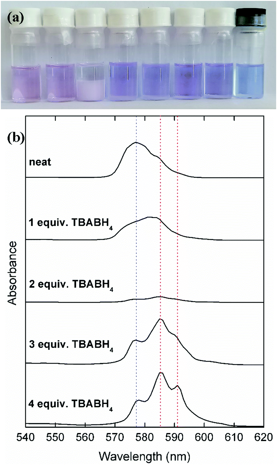 | ||
| Fig. 1 (a) Photograph of solutions of 0.1 mol L−1 Nd(Tf2N)3 + from left to right, 0, 1, 2, 3, 4 molar equivalents of TBABH4 in DME, 4 molar equivalents of NaBH4 in DME, 4 molar equivalents of LiBH4 in DME, and a solution of 0.1 mol L−1 Nd2Cl6(DME)4 and 4 molar equivalents of LiBH4 in MeTHF. (b) UV-vis absorption spectra of the Nd(Tf2N)3–TBABH4 solutions. The blue and red dotted lines are an aid to visualize the appearance of new peaks due to the coordination with BH4−. | ||
A solution of neat Nd(Tf2N)3 in DME was observed to have a pale pink/purple color, with an overall absorption maximum at 577 nm. When TBABH4 was gradually added to this solution, a pale pink precipitate was first formed. When 2 molar equivalents of TBABH4 were added, a large amount of precipitate was observed and the solution became almost colorless. This indicates that at a Nd3+![[thin space (1/6-em)]](https://www.rsc.org/images/entities/char_2009.gif) :BH4− ratio of 1:2, a complex was formed which is poorly soluble in DME. When more TBABH4 was added, the precipitate dissolved, and a new soluble violet-colored complex was formed. This behavior was also observed in the UV-vis absorption spectra of the solutions, most notably by the decrease of the absorbance in the spectrum of the 1:2 complex solution (supernatant), and the appearance of two new intense absorption maxima at 585 nm and 591 nm in the spectrum of the Nd3+:BH4− 1:3 and 1:4 solutions. The complex formation was very similar for the other borohydride salts NaBH4 and LiBH4 (Fig. S1, ESI†). Moreover, a synergistic solubility effect was observed for the NaBH4-based solutions. On its own, this compound is only sparingly soluble in DME, but in the presence of Nd(Tf2N)3, it is possible to dissolve up to 4 molar equivalents. Thus, it is likely that the soluble violet-colored complex has a Nd3+:BH4− ratio of 1:4. Visseaux et al. have reviewed the coordination chemistry of rare earths and borohydride, and showed that complexes with several stoichiometries can be formed.45 Considering the synergistic solubility effect, the violet color can be attributed to the anionic tetrakis(borohydrido) neodymate(III) [Nd(BH4)4]− complex.46 The complex formation for the Dy(Tf2N)3 analogues was different, as homogeneous solutions were obtained for any Dy3+:BH4− ratio, and without any color change (Fig. S2, ESI†). However, the same synergistic solubility effect with NaBH4 was observed, indicating that the analogous [Dy(BH4)4]− complex was formed. Both the neodymium- and dysprosium-containing electrolytes also exhibited a high stability over time, as there were no changes in visual appearance or electrochemical behavior (vide infra) observed several days after the electrolytes were first prepared.
:BH4− ratio of 1:2, a complex was formed which is poorly soluble in DME. When more TBABH4 was added, the precipitate dissolved, and a new soluble violet-colored complex was formed. This behavior was also observed in the UV-vis absorption spectra of the solutions, most notably by the decrease of the absorbance in the spectrum of the 1:2 complex solution (supernatant), and the appearance of two new intense absorption maxima at 585 nm and 591 nm in the spectrum of the Nd3+:BH4− 1:3 and 1:4 solutions. The complex formation was very similar for the other borohydride salts NaBH4 and LiBH4 (Fig. S1, ESI†). Moreover, a synergistic solubility effect was observed for the NaBH4-based solutions. On its own, this compound is only sparingly soluble in DME, but in the presence of Nd(Tf2N)3, it is possible to dissolve up to 4 molar equivalents. Thus, it is likely that the soluble violet-colored complex has a Nd3+:BH4− ratio of 1:4. Visseaux et al. have reviewed the coordination chemistry of rare earths and borohydride, and showed that complexes with several stoichiometries can be formed.45 Considering the synergistic solubility effect, the violet color can be attributed to the anionic tetrakis(borohydrido) neodymate(III) [Nd(BH4)4]− complex.46 The complex formation for the Dy(Tf2N)3 analogues was different, as homogeneous solutions were obtained for any Dy3+:BH4− ratio, and without any color change (Fig. S2, ESI†). However, the same synergistic solubility effect with NaBH4 was observed, indicating that the analogous [Dy(BH4)4]− complex was formed. Both the neodymium- and dysprosium-containing electrolytes also exhibited a high stability over time, as there were no changes in visual appearance or electrochemical behavior (vide infra) observed several days after the electrolytes were first prepared.
In order to avoid the use of bistriflimide salts in the organic electrolytes, alternative trivalent rare-earth salts were also investigated. Krasovskiy et al. reported that anhydrous rare-earth(III) chlorides were highly soluble in tetrahydrofuran (THF), when combined with lithium chloride.47 We found that this was also the case when they were combined with LiBH4. Instead of THF, the greener and less volatile solvent 2-methyltetrahydrofuran (MeTHF) was used, and instead of the anhydrous LnCl3 salts, their DME adducts were used, as reported by Baisch et al.43 The Nd2Cl6(DME)4-based electrolytes have a violet color that is similar to the Nd(Tf2N)3-based electrolytes, indicating the formation of borohydride complexes. However, judging from the UV-vis absorption spectrum, the speciation might be different, as heteroleptic chloride–borohydride complexes have also been reported (Fig. S3, ESI†).45,48
Cyclic voltammetry
The cathodic behavior of the mixed Ln(Tf2N)3–BH4 electrolytes was characterized by cyclic voltammetry (CV) (Fig. 2). Because many different components are present in these organic electrolytes, considering each one separately can aid in understanding the overall electrochemical behavior. Mixtures of NaTf2N/LiTf2N and 4 molar equivalents of NaBH4/LiBH4 in DME showed the typical behavior associated with the electrodeposition and stripping of sodium and lithium metal (Fig. S4a, ESI†). For sodium, the deposition onset potential is around −3.2 V vs. Fc+/Fc, and for lithium it is around −3.4 V vs. Fc+/Fc, and a characteristic stripping peak can be observed in the backwards scan. For mixtures of Nd(Tf2N)3 and 4 molar equivalents of NaTf2N/LiTf2N, similar sodium or lithium deposition behavior is observed, but with decreased reversibility (Fig. S4b, ESI†). On the other hand, the cathodic behavior of the Nd(Tf2N)3–BH4 electrolytes is very different. A high-current cathodic wave with an onset around −3.0 V vs. Fc+/Fc is observed (Fig. 2a). For the NaBH4 and LiBH4 electrolytes, this onset is slightly less negative and the current density is larger than for the analogous TBABH4 electrolyte, but this is probably related to the lower electrical conductivity of the electrolyte due to the presence of the bulky TBA+ cation. For the NaBH4 and LiBH4 electrolytes, a small broad stripping peak is observed in the backwards scan. Considering that the electrodeposition of rare-earths is always irreversible, this indicates that co-deposition of sodium or lithium metal occurred. This is possible because the cathodic vertex potential of the experiment is sufficiently negative at −3.5 V. However, judging from the significantly more positive deposition onset, and the fact that it also occurs in the TBABH4 electrolyte, the process at −3.0 V vs. Fc+/Fc cannot be exclusively attributed to sodium or lithium deposition.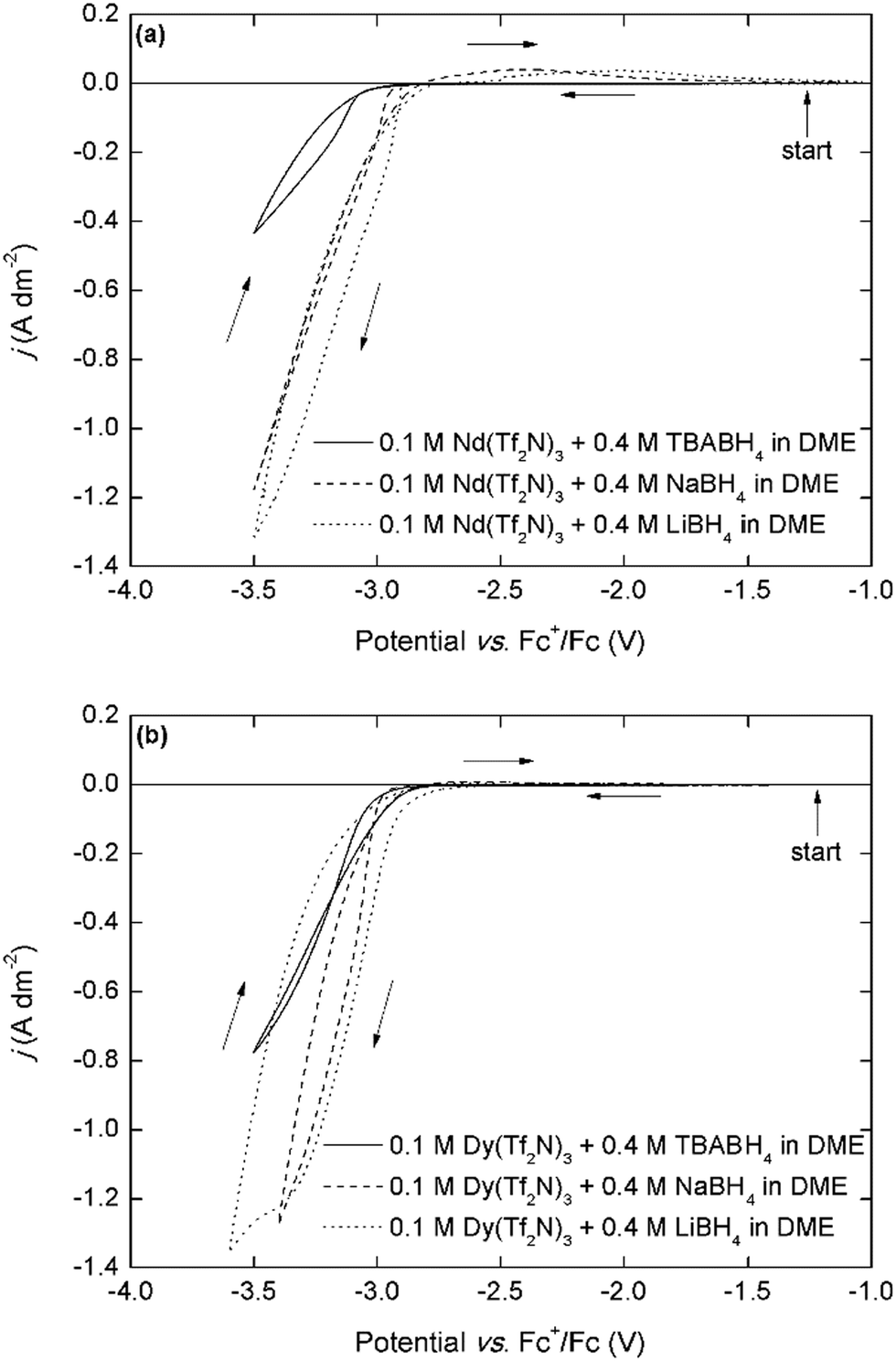 | ||
| Fig. 2 (a) Cyclic voltammograms (first cycle) of 0.1 mol L−1 Nd(Tf2N)3 + 4 molar equivalents of the borohydride salts recorded at a scan rate of 10 mV s−1, (b) cyclic voltammograms of 0.1 mol L−1 M Dy(Tf2N)3 + 4 molar equivalents of the borohydride salts recorded at a scan rate of 10 mV s−1. The scan direction is indicated with arrows. The working and counter electrodes were pieces of platinum-coated silicon wafers with a surface area of 0.003 dm2 and 0.01 dm2, respectively. The reference electrode was Fc+/Fc (0.005 mol L−1 each) dissolved in [BMP][Tf2N]. | ||
The cyclic voltammograms that are recorded in the analogous Dy(Tf2N)3–BH4 electrolytes are very similar, with a deposition onset around −3.0 V vs. Fc+/Fc and the same trend in current density (Fig. 2b). These deposition onset potentials are also very similar to those previously reported for neodymium and dysprosium electrodeposition in ionic liquids that use the Fc+/Fc reference couple.10,11,19 Furthermore, the presence of nucleation hysteresis for both elements in the respective CVs, and the presence of a black residue on the working electrode post-experiment strongly support the possibility of metallic RE electrodeposition. Fig. 3a depicts cyclic voltammograms that have been recorded in electrolytes with varying Nd3+:TBABH4 ratios.
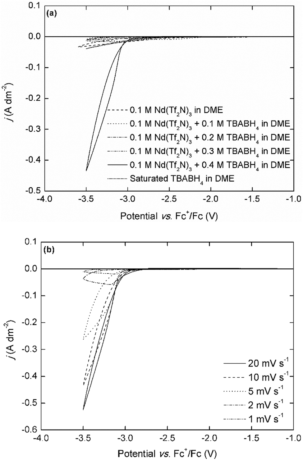 | ||
| Fig. 3 (a) Cyclic voltammograms (first cycle) of 0.1 mol L−1 Nd(Tf2N)3 + 0 to 4 molar equivalents of TBABH4 recorded at a scan rate of 10 mV s−1. (b) Cyclic voltammograms of 0.1 mol L−1 Nd(Tf2N)3 + 4 molar equivalents of TBABH4 recorded at varying scan rate. The working and counter electrodes were pieces of platinum-coated silicon wafers with a surface area of 0.003 dm2 and 0.01 dm2, respectively. The reference electrode was Fc+/Fc (0.005 mol L−1 each) dissolved in [BMP][Tf2N]. | ||
Interestingly, the electrodeposition wave is only observed in the electrolyte with a Nd3+:TBABH4 ratio of 1:4, whereas only very small currents (j < 0.05 A dm−2) can flow in the electrolytes with other compositions. This was also observed in the NaBH4- and LiBH4-based electrolytes, but in those electrolytes the electrodeposition of sodium or lithium was also observed at the expected potentials (Fig. S5, ESI†). Although it is difficult to make any conclusions on the electrodeposition mechanism based on only simple cyclic voltammetry experiments, this behavior strongly indicates that the formation of a redox-active complex, [Nd(BH4)4]−, plays an important role. Furthermore, these results also suggest a different mechanism than the one hypothesized by Ta et al, i.e. that the adsorption of BH4− on the electrode surface and subsequent chemical reaction is the rate-determining step.40 The scan rate-dependence of the current density is indicative for the occurrence of passivation processes (Fig. 3b). At very low scan rates (≤2 mV s−1), the current density is very small, and reaches a limit around −3.1 V vs. Fc+/Fc. For the analogous dysprosium(III)-containing electrolytes, a similar negative trend and appearance of a maximum current density is observed except for the electrolytes with TBABH4 (Fig. S6, ESI†). However, the decrease in current density is less pronounced than for neodymium. This can be explained by the difference in reactivity of both metals. All REEs are reactive metals and are prone to react with electrolyte components (bistriflimide) and form passivating surface films, leading to increased resistance. Thus, as the scan rate is decreased, the deposit surface is completely passivated before the cathodic vertex potential is reached, and the current density decreases. Since neodymium is more reactive than dysprosium, this effect is more pronounced. The electrodeposition of neodymium was also investigated in the chloride-based electrolytes (Fig. 4).
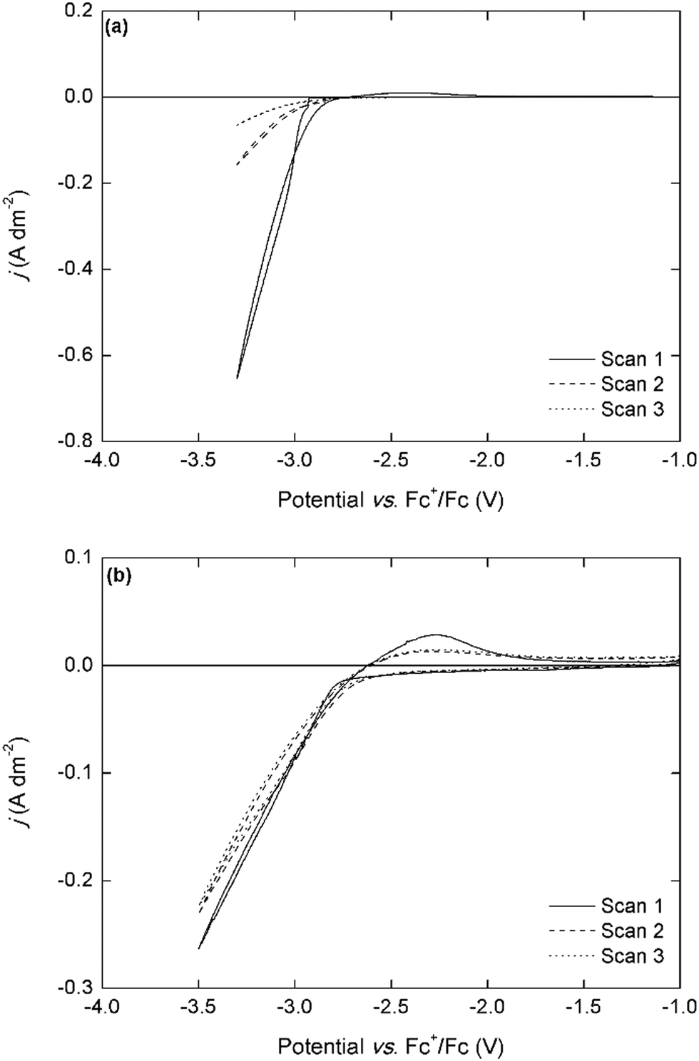 | ||
| Fig. 4 (a) Cyclic voltammograms of 0.1 mol L−1 Nd(Tf2N)3 + 4 molar equivalents of LiBH4 in DME and (b) cyclic voltammograms of 0.05 mol L−1 Nd2Cl6(DME)4 + 4 molar equivalents of LiBH4 in MeTHF, recorded over 3 cycles at a scan rate of 10 mV s−1. The working and counter electrodes were pieces of platinum-coated silicon wafers with a surface area of 0.003 dm2 and 0.01 dm2, respectively. The reference electrode was Fc+/Fc (0.005 mol L−1 each) dissolved in [BMP][Tf2N]. | ||
In the CV of the chloride-based electrolyte, the deposition onset potential is observed at a slightly less negative potential of −2.9 V vs. Fc+/Fc, and a small stripping peak is observed in the backwards scan, indicating co-deposition of lithium metal. The current densities are significantly lower than for the bistriflimide-based electrolytes. This might be related to differences in speciation of neodymium in both electrolytes and their consequences on the mass transport to the electrode. However, the magnitude of the current density remains the same in the subsequent cycles, whereas with the bistriflimide-based electrolyte, the current density strongly decreased after the first cycle. This can be attributed to the differences in sensitivity of the anions to reduction. The chloride anion is not reactive towards the strongly reducing neodymium deposit, whereas the bistriflimide anion can be reduced leading to passivating surface films on the cathode.20–24 This is an important consideration in order to achieve stable long-term electrowinning of REEs.
Potentiostatic electrodeposition
Electrodeposition of neodymium and dysprosium was performed potentiostatically at −3.1 V vs. Fc+/Fc for the LiBH4 and NaBH4 electrolytes in order to avoid excessive co-deposition of sodium or lithium metal. For the TBABH4 electrolytes, the potential was −3.4 V vs. Fc+/Fc to compensate for the higher solution resistance (Fig. 5).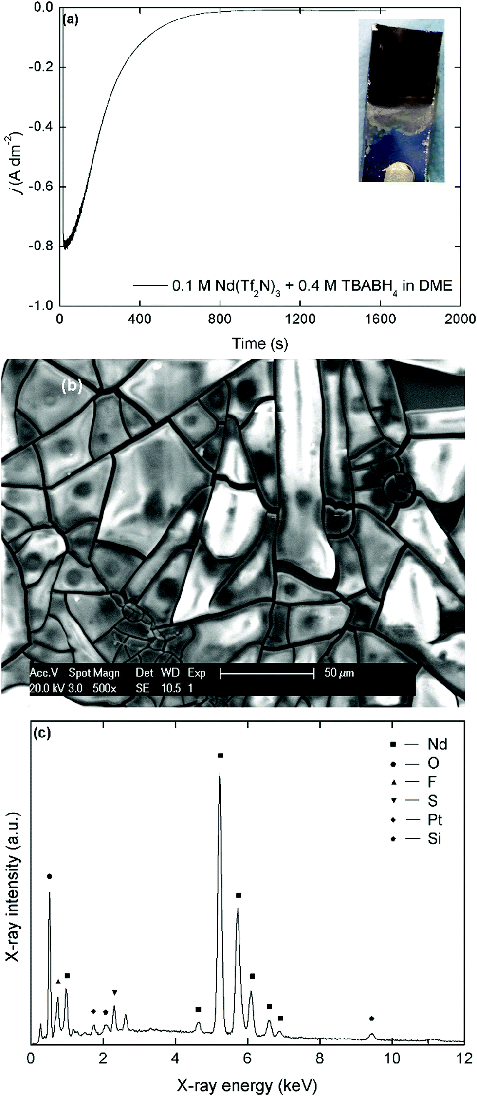 | ||
| Fig. 5 (a) Plot of the current density versus time for a potentiostatic deposition at −3.4 V vs. Fc+/Fc for 1600 s in a stirred solution of 0.1 mol L−1 Nd(Tf2N)3 + 4 molar equivalents of TBABH4 in DME. Inset: Picture of the fresh deposit on a platinum-coated silicon wafer substrate. (b) Scanning electron micrograph of the deposit at X500 magnification. (c) EDX spectrum of the deposit in the energy range 0–12 keV, recorded at an acceleration voltage of 20 kV with assignment of the major lines. | ||
All the deposits that were obtained from the organic electrolytes had a matt black or brown appearance, depending on the layer thickness. However, the color of the deposits quickly changed to white or light blue once exposed to air, which indicates a strong sensitivity to oxidation, as is expected from metallic REEs.18,19 During the preparation of the samples for SEM and EDX analysis, exposure to air could not be avoided and significant oxidation occurred. The broken, shard-like morphology of the deposits is probably a consequence of this oxidation and/or internal stresses during the deposition process. Initially, a high current density was recorded during deposition (j = 0.8 A dm−2), but a fast decrease was observed and after 800 seconds, barely any current flow remained (j < 0.01 A dm−2). This behavior supports the observations during the voltammetry experiments that insulating surface layers are formed on the reactive deposits due to side reactions with electrolyte components. In the accompanying EDX spectrum, the most intense peaks correspond to neodymium (Mα = 0.978 keV, Lα = 5.229 keV) and oxygen (Kα = 0.525 keV). The estimated Nd:O molar ratio is 2:3, indicating that Nd2O3 is the main component after exposure of the deposits to air. However, peaks of fluorine (Kα = 0.677 keV), and sulfur (Kα = 2.307 keV) are observed as well. This supports the hypothesis that the passivating films are caused by the reduction of the bistiflimide anion on the deposit surface. The morphology and elemental composition for deposits prepared in the analogous NaBH4 and LiBH4 electrolytes were similar (Fig. S7 and S8, ESI†). However, the presence of sodium is also observed in the EDX spectrum of the deposit that was prepared in the NaBH4 electrolyte (Fig. S9, ESI†). This confirms that some co-deposition of sodium occurred, even at a deposition potential of −3.1 V vs. Fc+/Fc. This is probably also the case for lithium, but this element is too light to be detected by EDX analysis. For the dysprosium-containing electrolytes, similar matt black deposits with a broken morphology were obtained (Fig. 6).
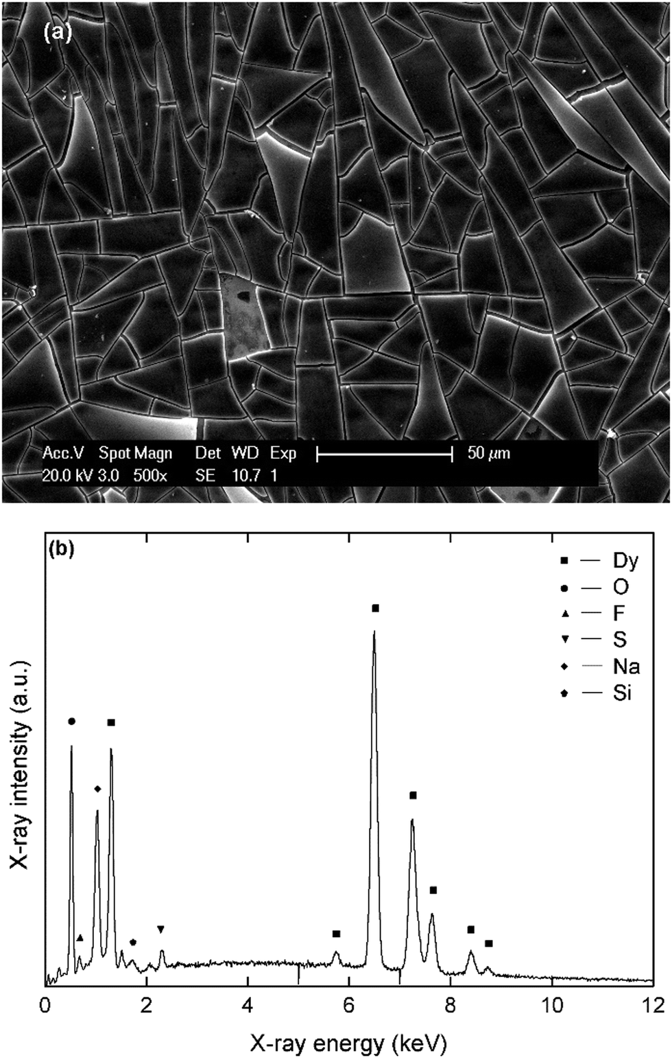 | ||
| Fig. 6 (a) SEM micrograph of a dysprosium deposit, prepared at −3.1 V vs. Fc+/Fc for 1800 s on a platinum-coated silicon wafer substrate in a stirred solution of 0.1 mol L−1 Dy(Tf2N)3 + 4 molar equivalents of NaBH4 in DME. (b) EDX spectrum of the deposit in the energy range 0–12 keV, recorded at an acceleration voltage of 20 kV with assignment of the major lines. | ||
According to EDX analysis, dysprosium (Mα = 1.293 keV, Lα = 6.494) and oxygen (Kα = 0.525 keV) are the major elements present in the deposit after exposure to air. The Dy:O molar ratio is 2:3, indicating that Dy2O3 is the main component. Here, the co-deposition of sodium can be observed more easily, as there is no overlap between the characteristic X-ray line of sodium (Kα = 1.041 keV) and lines corresponding to other elements. However, this element is always present in a lesser amount (<10 atomic%) than dysprosium (25–35 atomic%). The presence of fluorine and sulfur is also observed, confirming that passivation also occurred during electrodeposition of this element.
Deposits that were obtained in chloride-based organic electrolytes (Nd2Cl6(DME)4 + 4 molar equivalents of LiBH4 in MeTHF) have a similar matt black appearance, sensitivity to oxidation and shard-like morphology (Fig. 7). However, the course of the current density over time during deposition is different compared to the bistriflimide-based electrolytes. Where for the latter case, an initially high current density was observed followed by a fast decrease due to surface passivation phenomena, the initial current density in the chloride-based electrolytes was lower, but remained more stable during deposition. This behavior is reminiscent to the CVs recorded over several cycles and confirms that passivation is much less pronounced in these electrolytes compared to the bistriflimide-based electrolytes due to the stability of the chloride anion against reduction. Evidently, fluorine and sulfur are not observed in the EDX spectra of these deposits, but chlorine is one of the major elements that is present. The estimated molar content of chlorine is approximately equal to that of neodymium, so it is not due to NdCl3. One possibility is that reduced neodymium halide clusters are formed by electrolysis in these electrolytes, instead of neodymium metal.49
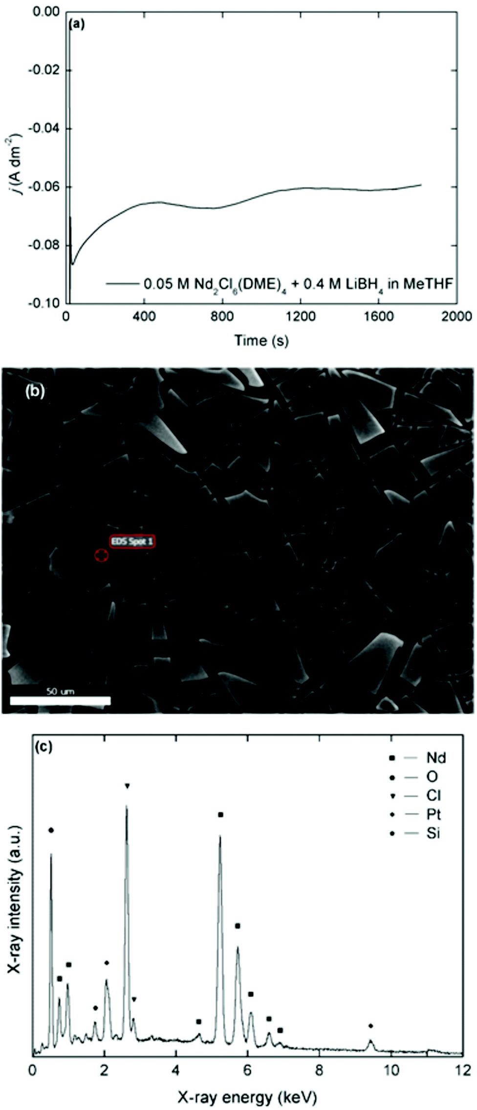 | ||
| Fig. 7 (a) Plot of the current density versus time for a potentiostatic deposition at −3.3 V vs. Fc+/Fc for 1800 s in a stirred solution of 0.05 mol L−1 Nd2Cl6(DME)4 + 4 molar equivalents of LiBH4 in MeTHF. (b) Scanning electron micrograph of the deposit at X500 magnification. (c) EDX spectrum of the deposit in the energy range 0–12 keV, recorded at an acceleration voltage of 20 kV with assignment of the major lines. | ||
EDX analysis is useful to determine the elemental composition of the neodymium and dysprosium deposits, but does not provide information on the chemical state (i.e. the oxidation state) of the elements. Moreover, the samples that are discussed above are oxidized from exposure to air during sample preparation, and are therefore not an accurate representation of a fresh deposit. X-ray photoelectron spectroscopy (XPS) is the benchmark characterization technique to determine whether the deposits are in the metallic state, as it provides information on the electron binding energies of the elements, and thus their oxidation state. Freshly prepared deposits from the TBABH4 electrolytes were transported under inert atmosphere and directly attached to the ultra-high-vacuum (UHV) system of the XPS instrument to avoid exposure of the samples to air. Fig. 8 depicts the Nd 3d5/2 and Dy 4d XPS spectra measured at the surface of deposits obtained from 0.1 mol L−1 Nd(Tf2N)3 or Dy(Tf2N)3 + 0.4 mol L−1 TBABH4 in DME. The experimental peak was fitted with Gaussian–Lorentzian peaks from Nd or Dy metal and their trivalent oxides. The fitted C 1s spectra (mainly from C–H bonds at 285.2 eV), which were used for the calibration of the other peaks are included in the ESI† (Fig. S10).
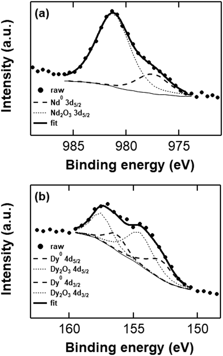 | ||
| Fig. 8 Curve-fitted Nd 3d5/2 (a) and Dy 4d (b) XPS spectra (surface) from deposits with a thickness of approx. 1 μm, obtained from potentiostatic deposition in Nd(Tf2N)3 or Dy(Tf2N)3 + TBABH4 electrolytes at −3.4 V vs. Fc+/Fc. | ||
The integrated fitted peak of Nd0 (dashed curve) at 978 eV corresponds to 28% of the total multipeak. Therefore, it can be estimated that 28 atomic% at the deposit surface consists of metallic neodymium, and the residual 72 atomic% are oxidized neodymium species (mainly oxide) as a result of passivation phenomena and possibly minor oxidation during sample transport. In order to determine the possible presence of neodymium fluoride, the peak fitting of Nd 3d3/2 has also been performed (Fig. S11, ESI†). The atomic% of metallic neodymium is 22% while oxidized neodymium species consist of 78% of the peak area, without any trace amount of fluoride, confirming the credibility of the estimation predicted by Nd 3d5/2 peak fitting. Furthermore, in the XPS survey scan of the neodymium deposit, no peaks are observed that correspond to fluorine, which are usually located in the range 684–690 eV (Fig. S12a, ESI†). In the Dy 4d XPS spectrum that was measured at the surface of an analogous dysprosium deposit, the experimental peak was fitted with peaks from Dy2O3 and Dy metal. The integrated fitted peak of Dy0 (dashed curve) at 154.8 eV corresponds to 35% of the total multipeak. The residual 65 atomic% are oxidized dysprosium species (oxides + some fluorides). In this case, a higher fraction of fluorides was observed in the spectrum, which is supported by the presence of a peak in the range 684–690 eV in the survey scan of the deposit (Fig. S12b, ESI†). Despite minimizing the exposure to air, both samples contained a considerable amount of oxygen-containing species at the surface (Fig. S13, ESI†). Other than from the Ln(III) oxides, this might also originate from reduced solvent (e.g. alkoxides) or anion species that are covalently bound to the deposit surface.
Conclusion
The electrodeposition of neodymium and dysprosium has been demonstrated from organic electrolytes at room temperature. The electrolytes consisted of a redox-active borohydride complex [Cation][Ln(BH4)4] (cation = Na, Li, TBA and Ln = Nd, Dy), dissolved in DME or MeTHF. For the NaBH4- and LiBH4-based electrolytes, higher current densities could be achieved during electrodeposition, but co-deposition of sodium or lithium was observed. With the TBABH4-based electrolytes, co-deposition was avoided, but the current densities were much lower. In all the electrolytes that contained bis(trifluoromethylsulfonyl)imide salts, the formation of passivating surface layers occurred by reduction of this anion on the reactive REE deposits. This led to loss of current density during electrodeposition. Alternatively, electrolytes based on Nd2Cl6(DME)4 and LiBH4 dissolved in MeTHF were used, which circumvented this issue of passivation, but the deposits contained chloride. The deposits were characterized by different analytical techniques and XPS gave evidence for the presence of metallic rare earths, notwithstanding of the presence of an oxidized surface layer. We are convinced that these organic electrolytes are an important step forward to the electrowinning of rare-earth metals, without relying on expensive bistriflimide-containing ionic liquids, and that it can be considerably improved.Conflicts of interest
There are no conflicts to declare.Acknowledgements
The research leading to these results received funding from the European Research Council (ERC) under the European Union's Horizon 2020 Research and Innovation Programme: Grant Agreement 694078-Solvometallurgy for critical metals (SOLCRIMET). Bastiaan Opperdoes is acknowledged for providing the load-lock transport chamber and inserting the XPS samples in the ultra-high-vacuum system.References
- V. Balaram, Geosci. Front., 2019, 10, 1285–1303, DOI:10.1016/j.gsf.2018.12.005.
- E. Alonso, A. M. Sherman, T. J. Wallington, M. P. Everson, F. R. Field, R. Roth and R. E. Kirchain, Environ. Sci. Technol., 2012, 46, 3406–3414, DOI:10.1021/es203518d.
- K. Binnemans, P. T. Jones, B. Blanpain, T. Van Gerven, Y. Yang, A. Walton and M. Buchert, J. Cleaner Prod., 2013, 51, 1–22, DOI:10.1016/j.jclepro.2012.12.037.
- J. Serp, M. Allibert, A. Le Terrier, R. Malmbeck, M. Ougier, J. Rebizant and J.-P. Glatz, J. Electrochem. Soc., 2005, 152, C137–C172, DOI:10.1149/1.1859812.
- E. Stefanidaki, C. Hasiotis and C. Kontoyannis, Electrochim. Acta, 2001, 46, 2665–2670, DOI:10.1016/S0013-4686(01)00489-3.
- D. Shen and R. Akolkar, J. Electrochem. Soc., 2017, 164, H5292–H5298, DOI:10.1149/2.0451708jes.
- Y. S. Yang, M. L. Zhang, W. Han, P. Y. Sun, B. Liu, H. L. Jiang, T. Jiang, S. M. Peng, M. Li, K. Ye and Y. D. Yan, Electrochim. Acta, 2014, 118, 150–156, DOI:10.1016/j.electacta.2013.11.145.
- K. Binnemans, Chem. Rev., 2007, 107, 2592–2614, DOI:10.1021/cr050979c.
- E. Bourbos, I. Giannopoulou, A. Karantonis, I. Paspaliaris and D. Panias, J. Sustainable Metall., 2018, 4, 395–406, DOI:10.1007/s40831-018-0186-0.
- A. Kurachi, M. Matsumiya, K. Tsunashima and S. Kodama, J. Appl. Electrochem., 2012, 42, 961–968, DOI:10.1007/s10800-012-0463-8.
- R. Kazama, M. Matsumiya, N. Tsuda and K. Tsunashima, Electrochim. Acta, 2013, 113, 269–279, DOI:10.1016/j.electacta.2013.09.082.
- G. Suppan, M. Ruehrig, A. Kanitz and H. J. Gores, J. Electrochem. Soc., 2015, 162, D382–D388, DOI:10.1149/2.0911508jes.
- S. Legeai, S. Diliberto, N. Stein, C. Boulanger, J. Estager, N. Papaiconomou and M. Draye, Electrochem. Commun., 2008, 10, 1661–1664, DOI:10.1016/j.elecom.2008.08.005.
- L. M. Glukhov, A. A. Greish and L. M. Kustov, Russ. J. Phys. Chem. A, 2010, 84, 104–108, DOI:10.1134/S0036024410010206.
- H. Kondo, M. Matsumiya, K. Tsunashima and S. Kodama, Electrochim. Acta, 2012, 66, 313–319, DOI:10.1016/j.electacta.2012.01.101.
- N. Sasaya, M. Matsumiya and K. Tsunashima, Polyhedron, 2015, 85, 888–893, DOI:10.1016/j.poly.2014.10.019.
- M. Matsumiya, M. Ishii, R. Kazama and S. Kawakami, Electrochim. Acta, 2014, 146, 371–377, DOI:10.1016/J.electacta.2014.09.066.
- H. Kondo, M. Matsumiya, K. Tsunashima and S. Kodama, ECS Trans., 2013, 50, 529–538, DOI:10.1149/05011.0529ecst.
- L. Sanchez-Cupido, J. M. Pringle, A. L. Siriwardana, A. Unzurrunzaga, M. Hilder, M. Forsyth and C. Pozo-Gonzalo, J. Phys. Chem. Lett., 2019, 10, 289–294, DOI:10.1021/acs.jpclett.8b03203.
- N. de Vos, C. Maton and C. V. Stevens, ChemElectroChem, 2014, 1, 1258–1270, DOI:10.1002/celc.201402086.
- M. C. Kroon, W. Buijs, C. J. Peters and G.-J. Witkamp, Green Chem., 2006, 8, 241–245, 10.1039/b512724f.
- P. C. Howlett, E. I. Izgorodina, M. Forsyth and D. R. MacFarlane, Z. Phys. Chem., 2006, 220, 1483–1498, DOI:10.1524/zpch.2006.220.10.1483.
- M. Forsyth, W. C. Neil, P. C. Howlett, D. R. MacFarlane, B. R. W. Hinton, N. Rocher, T. F. Kemp and M. E. Smith, ACS Appl. Mater. Interfaces, 2009, 1, 1045–1052, DOI:10.1021/am900023j.
- P. C. Howlett, N. Brack, A. F. Hollenkamp, M. Forsyth and D. R. MacFarlane, J. Electrochem. Soc., 2006, 153, A595–A606, DOI:10.1149/1.2164726.
- W. Zhao and J. Sun, Chem. Rev., 2018, 118, 10349–10392, DOI:10.1021/acs.chemrev.8b00279.
- V. F. Scalfani, A. Al Alshaikh and J. E. Bara, Ind. Eng. Chem. Res., 2018, 57, 15971–15981, DOI:10.1021/acs.iecr.8b02573.
- D. Coleman and N. Gathergood, Chem. Soc. Rev., 2010, 39, 600–637, 10.1039/b817717c.
- M.-J. Deng, P.-Y. Chen, T.-I. Leong, I.-W. Sun, J.-K. Chang and W.-T. Tsai, Electrochem. Commun., 2008, 10, 213–216, DOI:10.1016/j.elecom.2007.11.026.
- X. Xu, S. Sturm, J. Zavasnik and K. Z. Rozman, ChemElectroChem, 2019, 6, 2860–2869, DOI:10.1002/celc.201900286.
- M. Razo-Negrete, R. Ortega-Borges, V. Zinovyeva, C. Cannes, C. Le Naour, G. Trejo-Córdova and Y. Meas, Int. J. Electrochem. Sci., 2019, 14, 10431–10447, DOI:10.20964/2019.11.16.
- M. Wu, N. R. Brooks, S. Schaltin, K. Binnemans and J. Fransaer, Phys. Chem. Chem. Phys., 2013, 15, 4955–4964, 10.1039/C3CP44554B.
- C. A. Berger, M. Arkhipova, G. Maas and T. Jacob, Nanoscale, 2016, 8, 13997–14003, 10.1039/c6nr01351a.
- W. Simka, D. Puszczyk and G. Nawrat, Electrochim. Acta, 2009, 54, 5307–5319, DOI:10.1016/j.electacta.2009.04.028.
- L. J. Small, J. M. Sears, T. N. Lambert, T. J. Boylea and R. F. Hess, RSC Adv., 2016, 6, 89564–89571, 10.1039/C6RA15061F.
- B. Zhang, Y. Yao, Z. Shi, J. Xu, Y. Liu and Z. Wang, J. Electrochem. Soc., 2019, 166, D218–D220, DOI:10.1149/2.1161906jes.
- G. Vanhoutte, N. R. Brooks, S. Schaltin, B. Opperdoes, L. Van Meervelt, J. P. Locquet, P. M. Vereecken, J. Fransaer and K. Binnemans, J. Phys. Chem. C, 2014, 118, 20152–20162, DOI:10.1021/jp505479x.
- P. Geysens, V. S. Rangasamy, S. Thayumanasundaram, K. Robeyns, L. Van Meervelt, J. P. Locquet, J. Fransaer and K. Binnemans, J. Phys. Chem. B, 2018, 122, 275–289, DOI:10.1021/acs.jpcb.7b10158.
- R. Mohtadi, M. Matsui, T. S. Arthur and S. J. Hwang, Angew. Chem., Int. Ed., 2012, 51, 9780–9783, DOI:10.1002/anie.201204913.
- D. Wang, X. Gao, Y. Chen, L. Jin, C. Kuss and P. G. Bruce, Nat. Mater., 2018, 17, 16–20, DOI:10.1038/nmat5036.
- K. Ta, R. Zhang, M. Shin, R. T. Rooney, E. K. Neumann and A. A. Gewirth, ACS Appl. Mater. Interfaces, 2019, 11, 21536–21542, DOI:10.1021/acsami.9b04926.
- T. Vander Hoogerstraete, N. R. Brooks, B. Onghena, L. Van Meervelt and K. Binnemans, CrystEngComm, 2015, 17, 7142–7149, 10.1039/c5ce01270h.
- L. Xue, C. W. Padgett, D. D. DesMarteau and W. T. Pennington, Solid State Sci., 2002, 4, 1535–1545, DOI:10.1016/S1293-2558(02)00050-X.
- U. Baisch, D. B. Dell’Amico, F. Calderazzo, R. Conti, L. Labella, F. Marchetti and E. A. Quadrelli, Inorg. Chim. Acta, 2004, 357, 1538–1548, DOI:10.1016/j.ica.2003.11.011.
- B. Richter, J. B. Grinderslev, K. T. Moller, M. Paskevicius and T. R. Jensen, Inorg. Chem., 2018, 57, 10768–10780, DOI:10.1021/acs.inorgchem.8b01398.
- M. Visseaux and F. Bonnet, Coord. Chem. Rev., 2011, 255, 374–420, DOI:10.1016/j.ccr.2010.09.016.
- V. D. Makhaev, A. P. Borisov and B. P. Tarasov, Russ. J. Inorg. Chem., 2000, 45, 40–45 Search PubMed.
- A. Krasovskiy, F. Kopp and P. Knochel, Angew. Chem., Int. Ed., 2006, 45, 467–500, DOI:10.1002/anie.200502485.
- A. Klein and R. W. H. Pohl, Z. Anorg. Allg. Chem., 2008, 634, 1388–1392, DOI:10.1002/zaac.200800095.
- G. Meyer, Chem. Rev., 1988, 88, 93–107, DOI:10.1021/cr00083a005.
Footnote |
| † Electronic supplementary information (ESI) available: UV-vis absorption spectra of Nd(Tf2N)3 + 4 equiv. borohydride salts in DME. Picture of Dy(Tf2N)3 + TBABH4 in various molar ratios in DME. UV-vis absorption spectrum of Nd2Cl6(DME)4 + 4 equiv. LiBH4 in MeTHF. CVs of Na and Li borohydride or bistriflimide in DME. CVs of Nd(Tf2N)3 + 4 equiv. NaBH4 or LiBH4 in DME. CVs of Dy(Tf2N)3 + 4 equiv. borohydride salts in DME at various scan rates. SEM micrographs and EDX spectra of a Nd deposit from Nd(Tf2N)3 + 4 equiv. NaBH4 or LiBH4 in DME. Zoomed in EDX spectra of Nd deposits from Nd(Tf2N)3 + 4 equiv. borohydride salts in DME. Curve-fitted C 1s and O 1s XPS spectra of Nd and Dy deposits. XPS survey scans of Nd and Dy deposits. See DOI: 10.1039/d0cp06606k |
| This journal is © the Owner Societies 2021 |