 Open Access Article
Creative Commons Attribution 3.0 Unported Licence
Constant-adiabaticity ultralow magnetic field manipulations of parahydrogen-induced polarization: application to an AA'X spin system
Bogdan A.
Rodin
 ab,
James
Eills
 *cd,
Román
Picazo-Frutos
cd,
Kirill F.
Sheberstov
 cd,
Dmitry
Budker
 cde and
Konstantin L.
Ivanov
 *ab
*ab
aInternational Tomography Center SB RAS, Novosibirsk, Russia
bNovosibirsk State University, Novosibirsk, Russia. E-mail: ivanov@tomo.nsc.ru
cJohannes-Gutenberg University, Mainz 55099, Germany. E-mail: eills@uni-mainz.de
dHelmholtz Institute Mainz, GSI Helmholtzzentrum für Schwerionenforschung, 55128 Mainz, Germany
eDepartment of Physics, University of California, Berkeley, CA 94720-7300, USA
First published on 22nd March 2021
Abstract
The field of magnetic resonance imaging with hyperpolarized contrast agents is rapidly expanding, and parahydrogen-induced polarization (PHIP) is emerging as an inexpensive and easy-to-implement method for generating the required hyperpolarized biomolecules. Hydrogenative PHIP delivers hyperpolarized proton spin order to a substrate via chemical addition of H2 in the spin-singlet state, but it is typically necessary to transfer the proton polarization to a heteronucleus (usually 13C) which has a longer spin lifetime. Adiabatic ultralow magnetic field manipulations can be used to induce the polarization transfer, but this is necessarily a slow process, which is undesirable since the spins continually relax back to thermal equilibrium. Here we demonstrate two constant-adiabaticity field sweep methods, one in which the field passes through zero, and one in which the field is swept from zero, for optimal polarization transfer on a model AA′X spin system, [1-13C]fumarate. We introduce a method for calculating the constant-adiabaticity magnetic field sweeps, and demonstrate that they enable approximately one order of magnitude faster spin-order conversion compared to linear sweeps. The present method can thus be utilized to manipulate nonthermal order in heteronuclear spin systems.
1 Introduction
Nuclear magnetic resonance (NMR) methods suffer from notoriously low sensitivity, which mostly limits the scope of magnetic resonance imaging (MRI) to observing water or fat molecules in the body. To overcome this limitation, hyperpolarization methods have been developed, allowing molecules to be produced with NMR signal enhancements on the order of 105 to 106 in a typical MRI scanner.1–3 This enables the detection of chemical species in vivo at much lower concentrations than would otherwise be possible, and this has allowed for biochemical reactions in the body to be tracked in real time.4–6 Fumarate is a metabolite that has been employed as a hyperpolarized biomarker; its rapid conversion to malate in vivo is indicative of cell necrosis.7–9Dissolution dynamic nuclear polarization (d-DNP) is currently the favored method to hyperpolarize biomolecules,10,11 but this method is cumbersome and comes with high associated costs. An appealing alternative is parahydrogen induced polarization (PHIP)12,13 which is a chemical method renowned for its low cost and accessibility. There are several molecules that have been hyperpolarized via PHIP and applied for in vivo studies.14–19 The source of nonthermal spin order in PHIP experiments is the singlet order of parahydrogen20 (pH2, molecular hydrogen in the nuclear spin-singlet state). Although pH2 does not have a magnetic moment and is thus NMR-silent, upon symmetry breaking (i.e. by rendering the two protons chemically or magnetically inequivalent) the nonthermal singlet order can be converted into observable NMR signals, which are strongly enhanced compared to those under equilibrium conditions. The first step for hydrogenative PHIP is a catalytic hydrogenation reaction (addition of H2 to a suitable substrate, usually one with an unsaturated C–C bond). When the two pH2-nascent protons occupy inequivalent positions in the reaction product the symmetry is broken, and NMR signal enhancements can be obtained. The magnetic interaction that induces symmetry breaking is typically a chemical shift difference, or inequivalent J-couplings to a third nucleus.
A common step in PHIP is transferring nonthermal spin order from the source spins – here the pH2-nascent protons – to target spins of choice, which are more suitable for NMR detection for various reasons (longer relaxation times, higher spectral resolution, lower background signals). A number of methods have been developed to transfer the pH2 spin order to various heteronuclei, via rf pulse methods at high field,14,21–34 or through coherent spin mixing under zero- to ultralow-field (ZULF) NMR conditions.35–42 In the ZULF regime, Larmor frequencies are small, and nuclear spins belonging to different isotopic species become “strongly coupled” – that is the difference in Larmor frequencies becomes comparable to the spin–spin couplings. Under these conditions, coherent exchange of polarization among the spins becomes possible.
A number of polarization-transfer techniques exploiting ultra-low magnetic field manipulations have been developed, for example one can:
(1) Perform the reaction with pH2 at ultralow magnetic field to induce spontaneous polarization transfer.40
(2) Perform the reaction with pH2 at high field, nonadiabatically drop to ultralow or zero field, and adiabatically return to high field.36–38 In this work we refer to this process as a field sweep from zero field (FS-f-Z). In previous literature this is commonly referred to as a magnetic field cycle.
(3) Perform the reaction with pH2 at high field, then adiabatically invert the magnetic field, passing through zero field.41,43 In this work we refer to this process as a field sweep through zero field (FS-t-Z).
All NMR methods using adiabatic variation of the spin Hamiltonian are confronted with a common problem: adiabatic processes are by definition slow, and spin relaxation can be significant. Relaxation of hyperpolarized samples is generally detrimental as it gives rise to irreversible decay of the nonthermal spin order back to thermal equilibrium. It is therefore desirable to use the fastest possible adiabatic variation without disturbing the adiabatic nature of the process.44–47 Solutions have been proposed such as “fast” adiabatic processes given by optimal control theory48 or by varying the Hamiltonian Ĥ(t) such that the effective adiabaticity parameter is constant at all times.49 The latter approach, constant-adiabaticity, is easy to implement and to adapt to specific molecular cases.
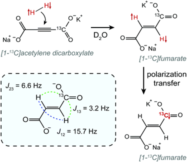
In this work we demonstrate constant-adiabaticity ultralow magnetic field manipulations to transfer proton singlet order into 13C magnetization in PHIP-polarized [1-13C]fumarate. We form hyperpolarized fumarate by chemical reaction of para-enriched hydrogen with an acetylene dicarboxylate precursor molecule50 (see Fig. 1). The protons are initially in the singlet state, and are scalar-coupled to the 13C spin in the carboxylate position (we work at natural 13C abundance). In the case of [1-13C]fumarate, the J-coupling between the protons is significantly larger than the proton-carbon J-couplings; this is referred to as the “near-equivalence” regime. As a consequence, the proton singlet state is close to an eigenstate, and significant state mixing which allows for polarization transfer occurs only at well-defined magnetic fields, ±B(i)LAC, corresponding to the i-th level anti-crossings (LACs) of the spin system.41 Here we specifically investigate two ZULF methods to perform polarization transfer: a field sweep from zero field, which uses a magnetic field variation from zero to Bmax, and a field sweep through zero field, which uses a magnetic field variation from −Bmax to Bmax. For the case of [1-13C]fumarate, Bmax is a few μT, which is considerably higher than the LAC fields, B(i)LAC. For both FS-f-Z and FS-t-Z experiments we derive constant-adiabaticity magnetic field profiles, B(t), and compare the performance with linear (uniform) field variations.
2 Theory
2.1 Hamiltonian
The Hamiltonian of two protons, the I spins (I1 and I2), and a 13C nucleus, the S spin (S3), in an external magnetic field B(t) (aligned along the z-axis) is written as:| Ĥ(t) = ĤZ(t) + ĤJ, | (1) |
| ĤZ(t) = −B(t){γI(Î1z + Î2z) + γSŜ3z}, | (2) |
| ĤJ = 2πJ12(Î1·Î2) + 2πJ13(Î1·Ŝ) + 2πJ23(Î2·Ŝ), | (3) |
| STZ = {|S12〉,|T12+〉,|T120〉,|T12−〉} ⊗ {|α3〉,|β3〉}. | (4) |
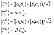 | (5) |
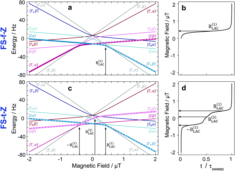
By plotting the eigenvalues of STZ′ as a function of magnetic field as shown in Fig. 2, it can be seen that there are a number of energy level-crossings. On close inspection, one can see that in four places the crossings are in fact avoided; the inequivalence in proton–carbon couplings acts as a small perturbation which lifts the degeneracy of the crossing states, and the level crossings are turned into LACs. The positions of the LACs have been determined previously:41
 | (6) |
 | (7) |
At LACs, coherent spin mixing comes into play, which can be exploited in polarization-transfer experiments. For instance, adiabatic passage through a LAC gives rise to swapping of the populations of the unperturbed STZ′ states (commonly termed diabatic states). The reason is that the populations follow the instantaneous eigenstates, i.e., the eigenstates of the full Hamiltonian (defined in the presence of the perturbation terms). Hereafter, by adiabatic variation of the Hamiltonian Ĥ(t) of a spin system under study we mean that its eigenstates |ψi(t)〉 vary with time so slowly that the state populations have sufficient time to adjust to such changes (populations “follow” the time-dependent states). The focus of this work is to optimize adiabatic passage through LACs through the use of constant-adiabaticity field profiles to minimize the passage time.
2.2 Density matrix
The nuclear spin state of pH2 is given by the pure singlet-state wavefunction, since the two protons are magnetically equivalent. At magnetic fields far from B(1)LAC the proton singlet state is also close to an eigenstate in [1-13C]fumarate. Hence, when the hydrogenation reaction takes place at a magnetic field far from B(1)LAC the singlet state remains close to an eigenstate. Note that the LACs at ±B(2)LAC occur between the proton triplet states, so the hydrogenation could be performed at zero-field and the proton singlet population still substantially retained. The initial density matrix is approximately: | (8) |
2.3 Constant adiabaticity profile
The general adiabaticity parameter is defined as:49 | (9) |
where i, j are the eigenstates of the Hamiltonian (1) and ωij = ωi − ωj is their energy difference (expressed in angular frequency units). Here the Haniltonian derivative is much easier to calculate then the eigenstate derivative. Hence, as dictated by eqn (9), for each pair of states we need to compute the parameter ξij, which defines how fast the eigenstates change with time compared to the internal evolution frequency given by ωij. After that, we evaluate the general adiabaticity parameter ξ by averaging over ξij defined for each pair of states. When ξ ≪ 1, the process is adiabatic and the populations remain in the instantaneous eigenstates.
In order to determine optimized B(t) ramps, we impose the condition that the general adiabaticity parameter is equal to a constant value, ξ(t) = ξ0, during the variation. Before proceeding, we introduce a few improvements for calculating constant-adiabaticity B(t) profiles.
First of all, to transfer populations between the diabatic states we use LACs, but there are also many level crossings in the system which occur between two states of degenerate energy when there are no perturbation terms to induce state mixing. Level crossings of a pair of levels occur when the Hamiltonian has a block-diagonal structure and the two states belong to different blocks. In the case under study, the block-diagonal structure of the Hamiltonian is dictated by the fact that the z-projection of the total spin is conserved, since the commutator [Ĥ, Î1z + Î2z + Ŝz] is zero. We exclude level crossings from consideration since, as follows from eqn (9), calculation of the |i〉ξij|j〉 parameter meets certain difficulties (the numerator and denominator tend to zero). Although this uncertainty in calculating ξij can be resolved analytically, numerical calculation of the adiabaticity parameter becomes problematic. Hence, we need to evaluate the ξij parameters only for the states belonging to the same blocks and eqn (9) can be modified as follows:
 | (10) |
Second, we take into account that in the case of [1-13C]fumarate prepared via PHIP, to a good approximation only the |Sα〉′ and |Sβ〉′ states are populated, which is only two states out of eight. To adiabatically manipulate the spin order, it is sufficient to consider only mixing of these states with other states belonging to the same blocks in the Hamiltonian. Specifically, the block of spin states characterized by the angular momentum projection on the field axis m = 1/2 comprises three states |T0α〉′, |Sα〉′ and |T+β〉′. If initially only the |Sα〉′ state is populated, spin mixing only in pairs of states |Sα〉′ ↔ |T0α〉′ and |Sα〉′ ↔ |T+β〉′ is important. To take this into account, eqn (10) should be modified as follows:
 | (11) |
With these two considerations, we can calculate the optimized B(t) profile. The time derivative of the Hamiltonian (1) is:
 | (12) |
 | (13) |
2.4 Polarization-transfer methods
The idea of the two methods considered here, FS-f-Z and FS-t-Z, is illustrated by the energy level diagrams shown in Fig. 2, which highlight the polarization-transfer pathways. In both experiments, the hydrogenation step is performed at +2 μT to produce [1-13C]fumarate with the |Sα〉′ and |Sβ〉′ states populated.In the FS-f-Z experiment, the field is then rapidly (nonadiabatically) dropped to zero, which preserves the populations of |Sα〉′ and |Sβ〉′, and then abiabatically increased to exchange the populations of |Sα〉′ and |T+β〉′, but leave the population of |Sβ〉′ unchanged. At the end of the process the |T+β〉′ and |Sβ〉′ states are populated, and hence the 13C spin is hyperpolarized. In this experiment only one LAC is relevant: the LAC at B(1)LAC.
In the FS-t-Z experiment, after the hydrogenation step the field is reversed rapidly (nonadiabatically) to −2 μT (although the hydrogenation could be done at −2 μT and this step skipped) which preserves the populations of |Sα〉′ and |Sβ〉′, and then increased adiabatically through zero to +2 μT. The population in |Sα〉′ ends in |T+β〉′, and the population in |Sβ〉′ ends in |T0β〉′. At the end of the process, the |T+β〉′ and |T0β〉′ states are populated, and hence the 13C spin is hyperpolarized. In this experiment three LACs are relevant: LACs occurring at the fields −B(1)LAC, B(1)LAC and B(2)LAC. Note that because −B(2)LAC is not part of the adiabatic pathway, the resulting field profile is slightly asymmetric with respect the center point.
In Fig. 2, we also show the constant adiabaticity B(t) sweeps for both cases. One can see that the proposed algorithm dictates a slow increase of the field at the LACs, whereas away from the LACs field sweeping can be fast.
3 Materials and methods
The constant adiabaticity profiles were calculated using eqn (13). However, dB itself is a function of time and cannot be calculated by direct integration of the expression. Therefore, the profiles were calculated incrementally: the first point was set to an initial value (0 or −2 μT) in the considered cases) and ξ0 was set to 1. The time increment, dt, should be small compared to 1/dB. For the considered cases dt = 10−4 s was small enough, meaning that the obtained profiles were smooth and did not significantly change upon further decrease of dt. The derivative dB was calculated using eqn (13) for each point of the profile and is used to find the next point: B(t + dt) = B(t) + dB(t) × dt. The number of points in the calculated profile depends on dt and the sweeping range, and was very large in the case of dt = 10−4 s. To obtain a profile with a convenient number of points we performed polynomial interpolation of the calculated profile and used 1000 points to reconstruct the profile. The described procedure and all simulations were implemented using the MATLAB environment, and the code is available on GitHub (see ref. 51).All chemicals were purchased from Sigma Aldrich. A solution of 50 mM monopotassium acetylene dicarboxylate, 100 mM sodium sulphite and 7 mM ruthenium catalyst [RuCp*(CH3CN)3]PF6 in D2O was prepared by dissolving the solids by heating and sonication. The sodium sulphite was added to increase the rate of reaction as discussed in ref. 52 and 53. The pH of the solution was adjusted to pH 10 with NaOD to further improve the rate of reaction. Oxygen was removed from the solution by bubbling nitrogen through for 5 min. 300 μL of this precursor solution was used for each experiment.
All experiments were performed at natural 13C abundance, but in experiments we specifically observe the [1-13C] isotopomer and generally refer to this molecule in the text.
The NMR experiments were performed in a 1.4 T 1H-13C dual resonance SpinSolve NMR system (Magritek, Aachen).
Parahydrogen at >98% enrichment was generated by passing hydrogen gas (>99.999% purity) through an Advanced Research Systems (ARS, Macungie, USA) parahydrogen generator operating at 25 K.
For ultralow-field experiments, a magnetic shield (MS-1F, Twinleaf LLC, Princeton, USA) was used to provide a 103 shielding factor from the laboratory field. Static internal magnetic fields for shimming were produced using built-in Bx, By, and Bz coils (on a flexible PCB), powered with computer-controlled DC calibrators (Krohn-Hite, model 523, Brockton, USA), providing three-axis field control to provide an additional order of magnitude in field reduction. The residual field in the shield was on the order of nanotesla, as verified with a fluxgate magnetometer. The time-dependent applied magnetic fields were generated with a Helmholtz coil (70 mm diameter) with 10 turns on each side, wound with 0.5 mm diameter copper wire onto a 3D-printed former, with current supplied by a power amplifier (AE Techron 7224, Elkhart, USA). The magnetic-field profiles were generated using a data acquisition card (NI-9263, National Instruments, Austin, USA) with 10 μs time precision.
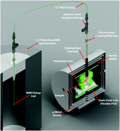
Low-pressure/vacuum J. Young NMR tubes held in the ZULF chamber and 1.4 T SpinSolve NMR spectrometer were connected with polytetrafluoroethylene (PTFE) tubing (1/16 in. O.D., 0.5 mm I.D.), as shown in Fig. 3. Gas and liquid flow were controlled by pneumatically actuated valves (Swagelok, Frankfurt, Germany). Sample hydrogenation was followed by shuttling into the SpinSolve by reversing the gas flow. The sample transport was performed with nitrogen gas (any unreactive gas could be used) and took 2.5 s. In order to prevent the sample from passing through any fields that could lead to undesired state-mixing during sample transport, a penetrating solenoid was used to provide a guiding field during transit out of the magnetic shield. To avoid having bubbles in the detection region after sample transport, 100 μL of acetone was placed in the SpinSolve tube at the start of each experiment. This mixed with the fumarate solution after shuttling, and served to reduce the surface tension and viscosity of the D2O solvent. The experimental apparatus is shown in Fig. 3.
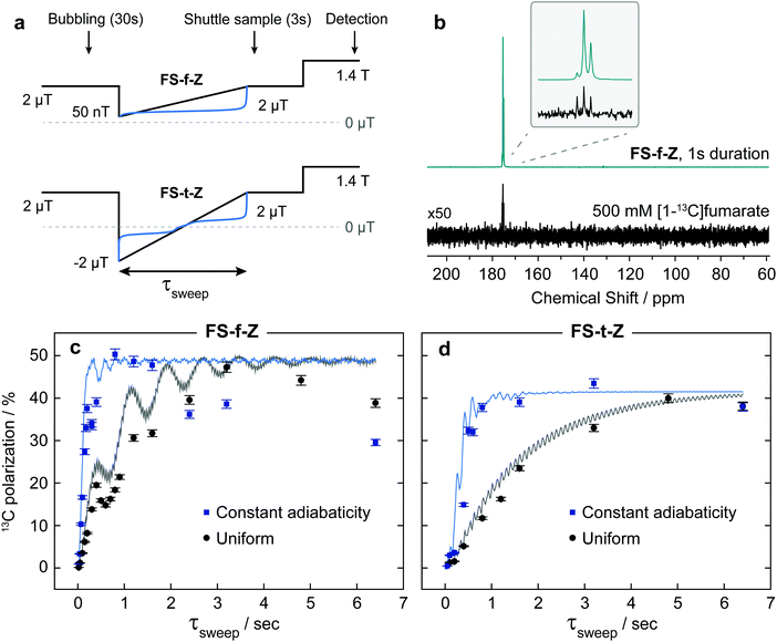
At the start of the experiment the sample was in the ZULF chamber in a 5 mm NMR tube, in a +2 μT (chosen as a relatively low field that is still high enough for the Hamiltonian eigenstates to be, to a good approximation, the STZ′ basis states) field provided by the Helmholtz coils, and parahydrogen gas was bubbled in at 7 bar for 30 s. After a 1 s delay to allow the sample to settle, a field manipulation was applied using the Helmholtz coils. After the field sweep, the solenoid guiding field was switched on to provide a +20 μT field, and nitrogen gas at 7 bar was used to shuttle the sample into the SpinSolve NMR spectrometer. After a 1 s delay for the sample to settle, a 90 pulse was applied followed by data acquisition. A simplified event sequence is shown in Fig. 4.
After the hyperpolarization had fully relaxed, a thermal equilibrium 1H NMR spectrum was acquired on each sample to quantify the concentration of fumarate formed. To calculate the polarization levels reported in Fig. 4(c and d), the hyperpolarized results were compared to a thermal equilibrium 13C NMR spectrum of an isotopically-enriched 500 mM [1-13C]fumarate standard in D2O.
4 Results and discussion
The results from experiments comparing linear and constant-adiabaticity field sweeping are shown in Fig. 4, with both the FS-f-Z and FS-t-Z experiments examined. Each data point represents the signal from one experimental run. Simulations of the transfer efficiency as a function of sweep duration are shown by the lines (which ignore relaxation effects). In both cases, using the constant-adiabaticity profile allows one to achieve the maximal 13C polarization faster than when using a linear profile by approximately one order of magnitude. The faster spin-order conversion helps to minimize loss of polarization due to relaxation, although in these particular experiments the observed 13C polarization is similar between the constant-adiabaticity and linear experiments. This is because the spin relaxation times are relatively long compared to the duration of the magnetic field manipulations, and significant polarization loss is only observed for long sweep durations. The overall sweep times are shorter for the FS-f-Z experiment which requires passage through only one LAC. Note that the nonadiabatic field reversal at the start of the FS-t-Z experiment was used for convenience, but is not expected to have any effect on the spin dynamics; the hydrogenation could equally be performed at B = −2 μT and the field adiabatically increased from there.To perform the spin dynamics simulations, firstly the density matrix is projected onto the eigenbasis of the Hamiltonian (1) defined at B = 2 μT and all off-diagonal elements (coherences) of the density matrix are removed, since they are averaged out upon continuous production of polarized molecule by the hydrogenation reaction. The resulting density matrix describes the spin system immediately following the hydrogenation step. Next, we numerically solve the Liouville–von Neumann equation with the time-dependent Hamiltonian (1), where B(t) corresponds to the magnetic field profile. Finally, we extract the expectation value of S-spin polarization from the final density matrix. Relaxation was not included in the simulations.
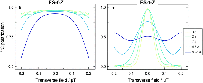
The experimental results are generally in good agreement with the simulations, but the 13C signals for the FS-t-Z experiments are notably lower than in the FS-f-Z experiments, with FS-f-Z showing ∼15% higher transfer efficiency. This is not intrinsic to the methodology, since both methods can lead to >97% 13C polarization in this molecular system. We believe the lower efficiency of the FS-t-Z is predominantly for two reasons. Firstly, in the FS-t-Z experiment, adiabatic passage through three LACs is necessary for polarization transfer, whereas for the FS-f-Z experiment only one LAC is used. Imperfections in the adiabatic passages will therefore compound, and be more detrimental in the FS-t-Z experiment. Secondly, and likely more importantly for most experimental cases, the requirement to pass through zero magnetic field for the FS-t-Z experiment can cause significant loss of polarization if there are residual magnetic fields along other axes. This introduces additional undesirable LACs which can lead to the populations being diverted from the desired transfer path. In Fig. 5 we show how the final 13C polarization for both FS-f-Z and FS-t-Z experiments with the sweep in the z-axis depends on the presence of a transverse field in the x/y-plane. We now use Bz to indicate a B field applied along the z-axis.
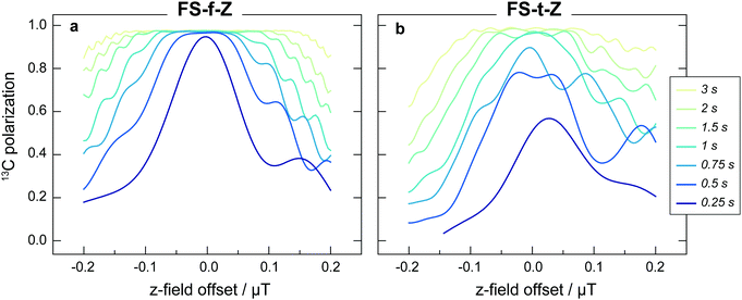
Despite shorter sweeping times when using a constant-adiabaticity profile, these methods are more sensitive to magnetic field offset in the field sweep axis (z) than the linear profiles. This is because the constant-adiabaticity profiles are designed around the knowledge of LAC fields, and if there is a magnetic field offset or inhomogeneity across the sample, the slow part of the constant-adiabaticity field ramp will not match the LAC field. The dependence of the constant-adiabaticity FS-f-Z and FS-t-Z conversion efficiencies on magnetic field offset is shown in Fig. 6. A Bz offset on the order of 100 nT is sufficient to reduce the transfer efficiency by >10%. The case is worse for the FS-t-Z experiment, which requires three LACs, compared to just one for the FS-f-Z experiment. We expect this situation can be improved by designing pseudo-constant-adiabaticity profiles to be close to constant-adiabaticity, but made to be more robust with respect to Bz field offset/inhomogeneity by broadening the LAC field condition.
In these experiments the FS-f-Z experiment performs better than the FS-t-Z. However, there are certainly experimental cases in which the FS-t-Z might be preferred. One example is in a system in which the rapid (nonadiabatic) initial field drop of the FS-f-Z is inconvenient or not possible, such as when instead of varying the magnetic field applied to a static liquid, a static magnetic field spatial profile is constructed and the liquid flows through to achieve the desired polarization transfer. Another example of when the FS-t-Z experiment may be preferred is for molecular systems outside the near-equivalence regime (i.e. when |J12| < |δJ|, in our case J12 = 15.7 Hz and δJ = 3.4 Hz). In these cases, the proton singlet state is no longer close to an eigenstate at zero field, and the nonadiabatic field switch at the start of the FS-f-Z experiment can cause the population differences to be converted into coherences which rapidly dephase. This can be avoided by using the FS-t-Z protocol which does not require nonadiabatic field changes.
For this work [1-13C]fumarate was chosen as a model system because it is a 3-spin system in the near-equivalence regime (J12 ≫ |J13 − J23|). This is the relevant regime for many PHIP-polarized molecules for which this inequality is similar or even more pronounced, with some examples being ethyl propionate,38 tetrafluoropropyl propionate,16 and allyl pyruvate.54 The greater this inequality, the greater the difference in time required for a linear sweep profile over its constant adiabaticity analog. On the other hand, [1-13C]fumarate is not an ideal molecule for the demonstration since the proton singlet lifetime and the 13C T1 are both relatively long,52 meaning there is little difference in the 13C polarization that can be reached whether using a constant adiabaticity or a linear sweep. This would certainly not be the result for molecules with more rapidly relaxing hyperpolarized spins, which is often the case when additional protons are present in the molecules.
5 Conclusions
In this work we revisited the concept of using adiabatic variation of the spin Hamiltonian for manipulating nonthermal spin order. By exploiting the constraint of “constant adiabaticity” we are able to increase the rate of spin-order transformations in nuclear spin systems. In addition to the previously developed algorithm, here we propose a modification of the method, allowing one to limit the number of adiabatic levels to only those relevant for the desired spin-order transfer. The theoretical approaches discussed here are of a general scope, and they can be applied to a variety of NMR (and non-NMR) experiments. We illustrate the performance of constant-adiabaticity optimization on the specific example of polarization transfer from parahydrogen-derived proton singlet order to a heteronuclear magnetization in an AA′X spin system in ZULF conditions. In such experiments the external magnetic field is adiabatically varied in the μT range; specifically, either the field is adiabatically increased from zero (FS-f-Z) or adiabatically inverted, passing through zero field (FS-t-Z). We demonstrate the methods on the molecule [1-13C]fumarate, and show that constant-adiabaticity B(t) ramps provide faster spin-order transfer than linear ramps, which is important when detrimental relaxation effects are considered. We expect that variation of the Hamiltonian using the constraint of constant adiabaticity will become a useful tool in NMR in general, and in ZULF NMR in particular.Conflicts of interest
There are no conflicts to declare.Acknowledgements
The authors would like to acknowledge Dr John W. Blanchard and Dr Teng Wu for experimental advice. This research was supported the Russian Science Foundation (project 20-62-47038). This project has received funding from the European Union's Horizon 2020 research and innovation programme under the Marie Skłodowska-Curie Grant Agreement No. 766402.Notes and references
- K. Münnemann and H. W. Spiess, Nat. Phys., 2011, 7, 522–523 Search PubMed.
- B. D. Ross, P. Bhattacharya, S. Wagner, T. Tran and N. Sailasuta, Am. J. Neuroradiol., 2010, 31, 24–33 Search PubMed.
- I. Park, P. E. Z. Larson, M. L. Zierhut, S. Hu, R. Bok, T. Ozawa, J. Kurhanewicz, D. B. Vigneron, S. R. VandenBerg, C. D. James and S. J. Nelson, Neuro-Oncology, 2010, 12, 133–144 Search PubMed.
- S. J. Nelson, J. Kurhanewicz, D. B. Vigneron, P. E. Z. Larson, A. L. Harzstark, M. Ferrone, M. van Criekinge, J. W. Chang, R. Bok, I. Park, G. Reed, L. Carvajal, E. J. Small, P. Munster, V. K. Weinberg, J. H. Ardenkjaer-Larsen, A. P. Chen, R. E. Hurd, L.-I. Odegardstuen, F. J. Robb, J. Tropp and J. A. Murray, Sci. Transl. Med., 2013, 5, 198ra108 Search PubMed.
- I. Marco-Rius and A. Comment, In Vivo Hyperpolarized 13C MRS and MRI Applications, American Cancer Society, 2018, pp. 167–178 Search PubMed.
- J. Kurhanewicz, D. B. Vigneron, J. H. Ardenkjaer-Larsen, J. A. Bankson, K. Brindle, C. H. Cunningham, F. A. Gallagher, K. R. Keshari, A. Kjaer, C. Laustsen, D. A. Mankoff, M. E. Merritt, S. J. Nelson, J. M. Pauly, P. Lee, S. Ronen, D. J. Tyler, S. S. Rajan, D. M. Spielman, L. Wald, X. Zhang, C. R. Malloy and R. Rizi, Neoplasia, 2019, 21, 1–16 CrossRef PubMed.
- F. A. Gallagher, M. I. Kettunen, D.-E. Hu, P. R. Jensen, R. I. Zandt, M. Karlsson, A. Gisselsson, S. K. Nelson, T. H. Witney, S. E. Bohndiek, G. Hansson, T. Peitersen, M. H. Lerche and K. M. Brindle, Proc. Natl. Acad. Sci. U. S. A., 2009, 106, 19801–19806 CrossRef CAS PubMed.
- J. J. Miller, A. Z. Lau, P. M. Nielsen, G. McMullen-Klein, A. J. Lewis, N. R. Jespersen, V. Ball, F. A. Gallagher, C. A. Carr, C. Laustsen, H. E. Bøtker, D. J. Tyler and M. A. Schroeder, JACC: Cardiovascular Imaging, 2018, 11, 1594–1606 CrossRef PubMed.
- P. M. Nielsen, A. Eldirdiri, L. B. Bertelsen, H. S. Jørgensen, J. H. Ardenkjaer-Larsen and C. Laustsen, Sci. Rep., 2017, 7, 40812 CrossRef CAS PubMed.
- J. H. Ardenkjaer-Larsen, B. Fridlund, A. Gram, G. Hansson, L. Hansson, M. H. Lerche, R. Servin, M. Thaning and K. Golman, Proc. Natl. Acad. Sci. U. S. A., 2003, 100, 10158–10163 CrossRef CAS PubMed.
- J. H. Ardenkjaer-Larsen, J. Magn. Reson., 2016, 264, 3–12 CrossRef CAS PubMed.
- J. Natterer and J. Bargon, Prog. Nucl. Magn. Reson. Spectrosc., 1997, 31, 293–315 CrossRef.
- S. B. Duckett and C. J. Sleigh, Prog. Nucl. Magn. Reson. Spectrosc., 1999, 34, 71–92 CrossRef CAS.
- P. Bhattacharya, E. Y. Chekmenev, W. H. Perman, K. C. Harris, A. P. Lin, V. A. Norton, C. T. Tan, B. D. Ross and D. P. Weitekamp, J. Magn. Reson., 2007, 186, 150–155 CrossRef CAS PubMed.
- N. M. Zacharias, H. R. Chan, N. Sailasuta, B. D. Ross and P. Bhattacharya, J. Am. Chem. Soc., 2012, 134, 934–943 CrossRef CAS PubMed.
- P. Bhattacharya, E. Y. Chekmenev, W. F. Reynolds, S. Wagner, N. Zacharias, H. R. Chan, R. Bunger and B. D. Ross, NMR Biomed., 2011, 24, 1023–1028 CrossRef CAS PubMed.
- A. M. Coffey, R. V. Shchepin, M. L. Truong, K. Wilkens, W. Pham and E. Y. Chekmenev, Anal. Chem., 2016, 88, 8279–8288 CrossRef CAS PubMed.
- A. M. Coffey, M. A. Feldman, R. V. Shchepin, D. A. Barskiy, M. L. Truong, W. Pham and E. Y. Chekmenev, J. Magnet. Reson., 2017, 281, 246–252 CrossRef CAS PubMed.
- O. G. Salnikov, R. V. Shchepin, N. V. Chukanov, L. Jaigirdar, W. Pham, K. V. Kovtunov, I. V. Koptyug and E. Y. Chekmenev, J. Phys. Chem. C, 2018, 122, 24740–24749 CrossRef CAS PubMed.
- C. R. Bowers and D. P. Weitekamp, J. Am. Chem. Soc., 1987, 109, 5541–5542 CrossRef CAS.
- M. Goldman, H. Jóhannesson, O. Axelsson and M. Karlsson, C. R. Chim., 2006, 9, 357–363 CrossRef CAS.
- S. Kadlecek, K. Emami, M. Ishii and R. Rizi, J. Magn. Reson., 2010, 205, 9–13 CrossRef CAS PubMed.
- S. Bär, T. Lange, D. Leibfritz, J. Hennig, D. von Elverfeldt and J. B. Hovener, J. Magn. Reson., 2012, 225, 25–35 CrossRef PubMed.
- A. N. Pravdivtsev, A. V. Yurkovskaya, N. N. Lukzen, K. L. Ivanov and H. M. Vieth, J. Phys. Chem. Lett., 2014, 5, 3421–3426 CrossRef CAS PubMed.
- J. Eills, G. Stevanato, C. Bengs, S. Glöggler, S. J. Elliott, J. Alonso-Valdesueiro, G. Pileio and M. H. Levitt, J. Magn. Reson., 2017, 274, 163–172 CrossRef CAS PubMed.
- G. Stevanato, J. Eills, C. Bengs and G. Pileio, J. Magn. Reson., 2017, 277, 169–178 CrossRef CAS PubMed.
- G. Stevanato, J. Magn. Reson., 2017, 274, 148–162 CrossRef CAS PubMed.
- A. B. Schmidt, S. Berner, W. Schimpf, C. Müller, T. Lickert, N. Schwaderlapp, S. Knecht, J. G. Skinner, A. Dost, P. Rovedo, J. Hennig, D. von Elverfeldt and J. B. Hövener, Nat. Commun., 2017, 8, 14535 CrossRef CAS PubMed.
- S. Korchak, S. Yang, S. Mamone and S. Glöggler, ChemistryOpen, 2018, 7, 344–348 CrossRef CAS PubMed.
- V. P. Kozinenko, A. S. Kiryutin, A. V. Yurkovskaya and K. L. Ivanov, J. Magn. Reson., 2019, 309, 106594 CrossRef CAS PubMed.
- J. Barkemeyer, M. Haake and J. Bargon, J. Am. Chem. Soc., 1995, 117, 2927–2928 CrossRef CAS.
- M. Haake, J. Am. Chem. Soc., 1996, 118, 8688–8691 CrossRef CAS.
- E. Y. Chekmenev, V. A. Norton, D. P. Weitekamp and P. Bhattacharya, J. Am. Chem. Soc., 2009, 131, 3164–3165 CrossRef CAS PubMed.
- A. S. Kiryutin, K. L. Ivanov, A. V. Yurkovskaya, H.-M. Vieth and N. N. Lukzen, Phys. Chem. Chem. Phys., 2013, 15, 14248–14255 RSC.
- M. Stephan, O. Kohlmann, H. G. Niessen, A. Eichhorn and J. Bargon, Magn. Reson. Chem., 2002, 40, 157–160 CrossRef CAS.
- H. Jóhannesson, O. Axelsson and M. Karlsson, C. R. Phys., 2004, 5, 315–324 CrossRef.
- M. Goldman, H. Jóhannesson, O. Axelsson and M. Karlsson, Magn. Reson. Imaging, 2005, 23, 153–157 CrossRef CAS PubMed.
- E. Cavallari, C. Carrera, T. Boi, S. Aime and F. Reineri, J. Phys. Chem. B, 2015, 119, 10035–10041 CrossRef CAS PubMed.
- L. T. Kuhn, U. Bommerich and J. Bargon, J. Phys. Chem. A, 2006, 110, 3521–3526 CrossRef CAS PubMed.
- A. N. Pravdivtsev, A. V. Yurkovskaya, H.-M. Vieth, K. L. Ivanov and R. Kaptein, ChemPhysChem, 2013, 14, 3327–3331 CrossRef CAS PubMed.
- J. Eills, J. W. Blanchard, T. Wu, C. Bengs, J. Hollenbach, D. Budker and M. H. Levitt, J. Chem. Phys., 2019, 150, 174202 CrossRef PubMed.
- F. Reineri, T. Boi and S. Aime, Nat. Commun., 2015, 6, 5858 CrossRef CAS PubMed.
- B. Joalland, A. B. Schmidt, M. S. H. Kabir, N. V. Chukanov, K. V. Kovtunov, I. V. Koptyug, J. Hennig, J. B. Hovener and E. Y. Chekmenev, Anal. Chem., 2020, 92, 1340–1345 CrossRef CAS PubMed.
- A. Messiah, Quantum Mechanics, Elsevier, North-Holland, Amsterdam, 1962 Search PubMed.
- S. Morita and H. Nishimori, J. Math. Phys., 2008, 49, 125210 CrossRef.
- K. Kaneko and H. Nishimori, J. Phys. Soc. Jpn., 2015, 84, 094001 CrossRef.
- J. Roland and N. J. Cerf, Phys. Rev. A: At., Mol., Opt. Phys., 2002, 65, 042308 CrossRef.
- B. A. Rodin, A. S. Kiryutin, A. V. Yurkovskaya, K. L. Ivanov, S. Yamamoto, K. Sato and T. Takui, J. Magn. Reson., 2018, 291, 14–22 CrossRef CAS PubMed.
- B. A. Rodin, K. F. Sheberstov, A. S. Kiryutin, J. T. Hill-Cousins, L. J. Brown, R. C. D. Brown, B. Jamain, H. Zimmermann, R. Z. Sagdeev, A. V. Yurkovskaya and K. L. Ivanov, J. Chem. Phys., 2019, 150, 064201 CrossRef PubMed.
- F. Reineri, S. Aime, R. Gobetto and C. Nervi, J. Chem. Phys., 2014, 140, 094307 CrossRef CAS PubMed.
- MATLAB files to calculate constant adiabaticity profiles, https://github.com/phagost/Constant_adiabaticity_profile.git.
- B. Ripka, J. Eills, H. Kouřilová, M. Leutzsch, M. H. Levitt and K. Münnemann, Chem. Commun., 2018, 54, 12246–12249 RSC.
- S. Knecht, J. W. Blanchard, D. Barskiy, E. Cavallari, L. Dagys, E. van Dyke, M. Tsukanov, B. Bliemel, K. Münnemann, S. Aime, F. Reineri, M. H. Levitt, G. Buntkowsky, A. Pines, P. Blümler, D. Budker and J. Eills, ChemRxiv, 2020, DOI:10.26434/chemrxiv.12909989.v1.
- E. Cavallari, C. Carrera, S. Aime and F. Reineri, J. Magn. Reson., 2018, 289, 12–17 CrossRef CAS PubMed.
| This journal is © the Owner Societies 2021 |

