
Boosting Li3V2(PO4)3 cathode stability using a concentrated aqueous electrolyte for high-voltage zinc batteries†
Cuixia
Li
a,
Wentao
Yuan
a,
Chi
Li
a,
Huan
Wang
a,
Liubin
Wang
a,
Yongchang
Liu
 *bc and
Ning
Zhang
*ac
*bc and
Ning
Zhang
*ac
aCollege of Chemistry & Environmental Science, Key Laboratory of Analytical Science and Technology of Hebei Province, Hebei University, Baoding 071002, China. E-mail: ningzhang@hbu.edu.cn
bInstitute for Advanced Materials and Technology, University of Science and Technology Beijing, Beijing 100083, China. E-mail: liuyc@ustb.edu.cn
cKey Laboratory of Advanced Energy Materials Chemistry (Ministry of Education), College of Chemistry, Nankai University, Tianjin 300071, China
First published on 25th February 2021
Abstract
We demonstrate that the capacity decay and voltage drop issues of the Li3V2(PO4)3 cathode are significantly addressed by using a concentrated aqueous electrolyte based on Zn and Li salts. The resultant aqueous Zn//Li3V2(PO4)3 battery achieves a high output voltage of 1.75 V and a long lifespan with 82.3% capacity retention over 2000 cycles. Joint structural and spectroscopic characterizations reveal that this battery operates through Li+ (de)intercalation into the cathode along with Zn2+ plating/stripping at the anode.
Rechargeable aqueous Zn-based batteries (RAZBs) are promising for large-scale energy storage because of the advantages of the metallic Zn anode, including abundant resources, low cost, environmental benignancy, and high theoretical gravimetric and volumetric capacity (820 mA h g−1 and 5855 mA h cm−3).1 Moreover, aqueous electrolytes intrinsically offer high safety and their excellent ionic conductivity favors high-rate capability.2 Cathode materials have been regarded as a critical component that govern the energy density and lifespan of batteries. Currently proposed cathodes for RAZBs generally exhibit limited average discharge voltage (e.g., MnO2 polymorphs ∽1.35 V,3 vanadium oxides ∽0.85 V,4 and organic compounds ∽1.1 V5 (vs. Zn2+/Zn)) or poor cycling stability.
Polyanion-type phosphate of Li3V2(PO4)3 (LVP) features a high working voltage (∽4.0 V vs. Li+/Li (∽1.8 V vs. Zn2+/Zn)) and a robust crystal architecture enabling fast ion (de)intercalation, and has been widely employed as a cathode for nonaqueous Li-ion batteries.6 Chen et al. explored the electrochemical behaviour of an aqueous battery constructed by an LVP cathode and Zn anode in 1 M Li2SO4-ZnSO4 electrolyte, showing the feasibility of LVP application in RAZBs.7 It should be noted that polyanion-type phosphates in aqueous media often suffer from serious dissolution of active materials,8 leading to a short lifespan and voltage drop during cycling. In addition, the traditional aqueous electrolytes (concentration generally below 2 mol L−1) cannot support the stable operation of high-voltage cathodes, due to the parasitic O2 evolution.6a,9 Therefore, it is desirable to improve the stability and reversibility of the LVP cathode for RAZBs, but it remains unsolved.
Here, we tackle the capacity decay and voltage drop issues of the LVP cathode using a formulated electrolyte composed of 1 m zinc trifluoromethanesulfonate (Zn(OTf)2) and 15 m lithium bis(trifluoromethanesulfonyl)imide (LiTFSI) in water (m, mol kg−1). This concentrated electrolyte can suppress the LVP dissolution and water-induced side reactions. As a result, a high output voltage of 1.75 V, a considerable energy density of 186.3 W h kgcathode−1, and a long-term stability with 82.3% capacity retention after 2000 cycles are characterized, which significantly stand out among those of the reported phosphate-based cathodes for RAZBs.
Fig. 1a presents the XRD Rietveld refinement of the as-prepared LVP. All of the diffraction peaks can be indexed to the monoclinic space group of P21/n and a good agreement between the experimental data and calculated result is achieved (Rwp = 4.92% and Rp = 3.85%). The refined lattice unit-cell parameters of a = 8.6200 Å, b = 8.6080 Å, c = 12.0541 Å, and V = 894.3950 Å3 match well with those in previous reports.10Fig. 1b schematically illustrates the crystal structure of LVP, which features a three-dimensional framework of VO6 octahedra and PO4 tetrahedra sharing O vertices and Li ions located in the interstitial space. As shown in the scanning electron microscopy (SEM) image (Fig. 1c), the as-prepared LVP/C composite has a nanoparticulate morphology and the particle size is in the range of 50–100 nm. The transmission electron microscopy (TEM) image further demonstrates that the LVP nanograins are uniformly and firmly confined in the carbon matrix (Fig. 1d). In the high-resolution TEM (HRTEM) image (Fig. 1e), the measured interplanar distance of 0.43 nm corresponds to the (020) plane of the monoclinic LVP. The crystalline particles are finely coated with an amorphous carbon shell. The Raman spectrum (Fig. S1, ESI†) shows two characteristic peaks at 1362 and 1581 cm−1 related to the defect-induced (D) band and graphitic-induced (G) band, respectively. The peak intensity ratio of the D to G band (ID/IG) is 0.9, suggesting a relatively high degree of graphitization that favours the electronic conductivity.10b The carbon content is determined to be 10.8% according to the thermogravimetric analysis (Fig. S2, ESI†). The scanning transmission electron microscopy (STEM) with elemental mapping images (Fig. 1f) confirm the uniform distribution of elements in the as-prepared composite.
 | ||
| Fig. 1 (a) Rietveld refined XRD pattern of the as-prepared LVP. (b) Schematic illustration of the LVP crystal structure. (c) SEM image. (d) TEM and (e) HRTEM images, with the inset presenting the corresponding FFT pattern. (f) STEM image with elemental mapping images. | ||
The electrochemical stability and reversibility of LVP cathodes in different aqueous electrolytes (i.e., 1 m Zn(OTf)2 (1 m Zn), 1 m Zn(OTf)2 + 5 m LiTFSI (1 m Zn + 5 m Li), 1 m Zn(OTf)2 + 10 m LiTFSI (1 m Zn + 10 m Li), and 1 m Zn(OTf)2 + 15 m LiTFSI (1 m Zn + 15 m Li)) have been studied. Although the ionic conductivity of electrolytes gradually decreases with increasing salt concentration, a considerable conductivity of 14.9 mS cm−1 is characterized in 1 m Zn + 15 m Li (Fig. S3, ESI†). Fig. 2a-c display the cyclic voltammetry (CV) curves of LVP electrodes in different electrolytes at 0.2 mV s−1. With the increase of LiTFSI content, the reversibility of the LVP cathode is significantly improved. Three stable pairs of redox peaks corresponding to the stepwise Li+ extraction/insertion from/into the LVP structure have been observed in 1 m Zn + 15 m Li electrolyte (Fig. 2a), suggesting that this concentrated electrolyte can effectively inhibit the LVP dissolution and suppress the water-induced side reactions. In sharp contrast, the dilute 1 m Zn (Fig. 2c) and 1 m Zn + 5 m Li (Fig. 2b) electrolytes cannot support the stable operation of LVP, showing a rapid peak current decay and an obvious O2 evolution reaction above 2.0 V (vs. Zn2+/Zn). The 1 m Zn + 10 m Li electrolyte moderately improves the stability of LVP with a slight decrease of the redox peaks upon cycling (Fig. S4, ESI†).
 | ||
| Fig. 2 (a-c) CV profiles and (d-f) typical charge/discharge curves of LVP cathodes in (a and d) 1 m Zn + 15 m Li, (b and e) 1 m Zn + 5 m Li, and (c and f) 1 m Zn electrolytes. (g) Cycling stability of LVP cathodes in different electrolytes at 200 mA g−1. (h) Long-term cycling performance of the LVP cathode in 1 m Zn + 15 m Li at 1000 mA g−1. (i) Raman spectra of different electrolytes (O-H stretching vibration). (j) Optical images of LVP electrodes immersed in different electrolytes after 10 days. | ||
Fig. 2d-f present the typical charge/discharge profiles of LVP cathodes at 200 mA g−1 within the voltage window of 0.6–2.1 V (vs. Zn2+/Zn). In 1 m Zn + 15 m Li electrolyte, the voltage profiles are well overlapped and a reversible capacity of 126.3 mA h g−1 at the 50th cycle is achieved. The three discharge platforms (1.75, 1.35, and 1.25 V) are consistent with the CV curves. Voltage profiles of LVP cathodes in 1 m Zn + 5 m Li (Fig. 2e) and 1 m Zn + 10 m Li (Fig. S5, ESI†) electrolytes suggest a better performance than that in 1 m Zn (Fig. 2d) but an inferior stability compared with the 1 m Zn + 15 m Li system. Fig. 2g displays the cycling performance of LVP cathodes in different aqueous electrolytes at 200 mA g−1. Impressively, the 1 m Zn + 15 m Li system enables the highest cycling stability with a reversible capacity of 126.7 mA h g−1 after 200 cycles without obvious decay. Moreover, the Coulombic efficiency (CE) can reach a high value of 99.8%. For comparison, the 1 m Zn + 5 m Li and 1 m Zn + 10 m Li counterparts exhibit much lower CE (Fig. S6, ESI†) and inferior capacity retentions of 76.1% after 100 cycles and 81.2% after 150 cycles, respectively. As expected, a shorter lifespan is observed in the neat 1 m Zn electrolyte. Thereafter, the long-term cycling stability of LVP in 1 m Zn + 15 m Li was evaluated at 1000 mA g−1 (Fig. 2h). The initial capacity increase is mainly due to the electrode activation process as identified by the reduced charge-transfer resistance during cycling (Fig. S7, ESI†). After 2000 cycles, a reversible capacity of 89.7 mA h g−1 with 82.3% capacity retention and ∽100% CE is achieved, indicating the feasibility of this battery system for practical applications.
Fig. 2i shows the Raman spectra of the hybrid Zn + Li electrolytes. The O-H stretching vibration of water molecules (2800–3700 cm−1) can be deconvolved into three components located at around 3115.5 (peak 1), 3366.1 (peak 2), and 3585.8 (peak 3) cm−1, corresponding to the strong, weak, and non H-bonds, respectively.5d With the increase of salt concentration, these H-bond signals experience blueshift and gradually weaken, indicating the decrease of water activity and the disruption of the H2O network connected by H-bonds. Similar evolution of the H2O signal has been confirmed by the Fourier transformed infrared (FTIR) spectra (Fig. S8, ESI†). The reduced water activity in the concentrated electrolyte helps to expand the electrochemical window with much reduced water-induced side reactions (Fig. S9, ESI†) and inhibit the dissolution of active materials. To intuitively identify the solubility of LVP, a static soaking experiment was conducted by loading LVP electrodes into different solutions (Fig. 2j). The 1 m Zn + 15 m Li media can remain colorless and transparent even after 10 days, but the solution colors in the 1 m Zn and 1 m Zn + 5 m Li counterparts turn deep yellow and light yellow, respectively, caused by the serious dissolution of LVP. In addition, the formulated 1 m Zn + 15 m Li electrolyte supports a good reversibility of a Zn anode (Fig. S10, ESI†), which contributes to the stable operation of Zn//LVP batteries.
The rate performance of LVP in 1 m Zn + 15 m Li is evaluated by progressively increasing the current densities from 200 to 2000 mA g−1 (Fig. 3a). Reversible capacities of 124.2, 120.5, 116.6, 111.2 and 107.6 mA h g−1 are delivered at rates of 300, 500, 800, 1000 and 1500 mA g−1, respectively. A high capacity of 100.5 mA h g−1 is achieved at 2000 mA g−1. An average capacity of 119.2 mA h g−1 recovers as the rate stepwise returns to 200 mA g−1. The typical voltage profiles (Fig. 3b) display an average output voltage of ∽1.5 V, corresponding to energy densities of 186.3 W h kgcathode−1 at 450 W kg−1 and 150.7 W h kgcathode−1 at 3000 W kg−1. Meanwhile, the assembled aqueous battery achieves an energy density of 143.1 W h kg−1 at 346.1 W kg−1 based on the mass of LVP cathode and 200% Zn anode. The electrode process kinetics were further studied by CV (Fig. 3c). The CV profiles maintain similar shapes with tiny shift as the scan rate increases from 0.2 to 1.2 mV s−1, demonstrating a good stability. According to the relation of i = avb (another type, log(i) = blog(v) + log(a)),11 the b values of the peaks O1, O2, O3, R1, R2, and R3 (marked in Fig. 3c) are determined to be 0.66, 0.65, 0.47, 0.66, 0.56, and 0.40 respectively (Fig. S11, ESI†). This demonstrates that a combination of diffusion and capacitive behaviors synergistically manages the charge-storage process of LVP, accounting for the high-rate capability. As calculated, a 56.5% fraction of the total charge is arising from the pseudocapacitive contribution (Fig. 3d, the calculation method is provided in the ESI†), which is comparable with other V-based cathodes.4a,11b,12 In addition, according to the galvanostatic intermittent titration technique (GITT, Fig. 3e and Fig. S12, ESI†), the ion diffusion coefficients range from 10−10 to 10−11 cm2 s−1, indicating the fast reaction kinetics.
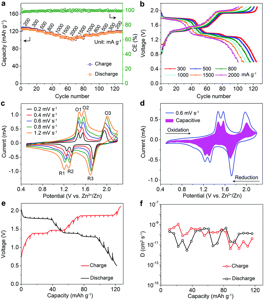 | ||
| Fig. 3 (a) Rate performance and (b) corresponding voltage profiles of the LVP cathode in 1 m Zn + 15 m Li electrolyte. (c) CV curves and (d) typical capacitive contribution at 0.6 mV s−1. (e) GITT profiles and (f) corresponding ion diffusion coefficient. | ||
The reaction mechanism of the LVP cathode in the hybrid 1 m Zn + 15 m Li aqueous electrolyte has been elucidated by a combination study of XRD, UV-visible (UV-vis) spectroscopy, X-ray photoelectron spectroscopy (XPS), and TEM analyses. Fig. 4a shows the initial two voltage profiles of LVP at 100 mA g−1, where the marked states (points A-I) were collected for the ex situ XRD and UV-vis measurements. Except for the signal of the Ti foil current collector, the characteristic (020), (210), (121), (−121), and (220) peaks of LVP are highly reversible during charge/discharge (Fig. 4b), ascribed to the Li+ extraction/insertionprocess. This XRD signal evolution of LVP is similar to the observation in the non-aqueous Li-based batteries.6b,10a The UV-vis spectra (Fig. 4c) record the evolution of the V oxidation states with the references of V2O5 (V5+), VOSO4 (V4+), and VCl3 (V3+). The pristine electrode features a typical absorption of V3+ with broad bands at around 440, 600 and 770 cm−1. Upon charging (A → C and E → G), the V4+ component intensifies along with the V3+ wane. At the fully charged state, a characteristic band of V4+ is detected, corresponding to the two-Li+ extraction from LVP. The discharge process (C → E and G → I) can revert the oxidation state of V to trivalence.
 | ||
| Fig. 4 (a) Voltage profiles during the initial two cycles. (b) XRD patterns and (c) UV-vis spectra at selected states (points A-I marked in (a)). XPS spectra of (d) V 2p and (e) Zn 2p regions. (f) Schematic illustration of the Zn//1 m Zn + 15 m Li//LVP battery chemistry. | ||
Fig. 4d and e show the variation of the V 2p and Zn 2p XPS regions, respectively. The V 2p3/2 (V 2p1/2) XPS peak shifts from the pristine location of 516.8 (524.1) eV to 517.6 (524.9) eV at the fully charged state, resulting from the oxidation process from V3+ to V4+.8c After fully discharging, these V 2p peaks can recover to the pristine sate. For Zn 2p spectra, no obvious Zn signal can be detected in the fully charged or discharged electrodes. This verifies that the cathode capacity comes from the Li+ intercalation with a negligible contribution from the Zn2+ intercalation. In addition, HRTEM images confirm the reversible contraction/expansion of the (020) plane of LVP caused by the Li+ extraction/insertion (Fig. S13, ESI†). STEM with the corresponding element mapping images reveal negligible Zn content in the discharged electrode (Fig. S13, ESI†), excluding the Zn2+ co-intercalation. According to the aforementioned results, the Zn//1 m Zn + 15 m Li//LVP battery chemistry operates though the reversible Li+ extraction/insertion from/into the LVP cathode and the Zn2+ electrochemical plating/stripping at the anode during charge/discharge (Fig. 4f).
In conclusion, we report a high-voltage and long-life LVP cathode for aqueous Zn-based batteries. The issues of capacity decay and voltage drop facing LVP are effectively addressed by the formulated 1 m Zn + 15 m Li electrolyte. The resultant LVP cathode exhibits a high output voltage of 1.75 V and a superior capacity retention of 82.3% after 2000 cycles. This Zn//LVP battery chemistry experiences reversible Li+ (de)intercalation into the polyanionic cathode along with Zn2+ plating/stripping at the anode during cycling. This work will inspire the design of efficient electrodes and electrolytes for rechargeable Zn-based batteries.
This work was supported by the National Natural Science Foundation of China (22075067, 21805066 and 21805007), Natural Science Foundation of Hebei Province (B202001001 and B2019201160), Top Young Talents Project of Hebei Education Department (BJ2019052), Beijing Natural Science Foundation (L182019), and Advanced Talents Incubation Program of Hebei University (521000981138).
Conflicts of interest
There are no conflicts to declare.References
- (a) N. Zhang, X. Chen, M. Yu, Z. Niu, F. Cheng and J. Chen, Chem. Soc. Rev., 2020, 49, 4203 RSC; (b) Z. Liu, Y. Huang, Y. Huang, Q. Yang, X. Li, Z. Huang and C. Zhi, Chem. Soc. Rev., 2020, 49, 180 RSC; (c) T. Zhang, Y. Tang, S. Guo, X. Cao, A. Pan, G. Fang, J. Zhou and S. Liang, Energy Environ. Sci., 2020, 13, 4625 RSC.
- (a) D. Chao, W. Zhou, F. Xie, C. Ye, H. Li, M. Jaroniec and S.-Z. Qiao, Sci. Adv., 2020, 6, eaba4098 CrossRef CAS PubMed; (b) H. Ao, Y. Zhao, J. Zhou, W. Cai, X. Zhang, Y. Zhu and Y. Qian, J. Mater. Chem. A, 2019, 7, 18708 RSC; (c) J. Huang, J. Zhou and S. Liang, Acta Phys.-Chim. Sin., 2021, 37, 2005020 Search PubMed.
- (a) J. Gao, X. Xie, S. Liang, B. Lu and J. Zhou, Nano-Micro Lett., 2021, 13, 69 CrossRef PubMed; (b) X. Zeng, J. Liu, J. Mao, J. Hao, Z. Wang, S. Zhou, C. D. Ling and Z. Guo, Adv. Energy Mater., 2020, 10, 1904163 CrossRef CAS; (c) N. Zhang, F. Cheng, J. Liu, L. Wang, X. Long, X. Liu, F. Li and J. Chen, Nat. Commun., 2017, 8, 405 CrossRef PubMed; (d) I. Stoševski, A. Bonakdarpour, F. Cuadra and D. P. Wilkinson, Chem. Commun., 2019, 55, 2082 RSC.
- (a) Y. Yang, Y. Tang, G. Fang, L. Shan, J. Guo, W. Zhang, C. Wang, L. Wang, J. Zhou and S. Liang, Energy Environ. Sci., 2018, 11, 3157 RSC; (b) X. Liu, H. Zhang, D. Geiger, J. Han, A. Varzi, U. Kaiser, A. Moretti and S. Passerini, Chem. Commun., 2019, 55, 2265 RSC; (c) C. Xia, J. Guo, Y. Lei, H. Liang, C. Zhao and H. N. Alshareef, Adv. Mater., 2018, 30, 1705580 CrossRef PubMed; (d) S. Islam, M. H. Alfaruqi, B. Sambandam, D. Y. Putro, S. Kim, J. Jo, S. Kim, V. Mathew and J. Kim, Chem. Commun., 2019, 55, 3793 RSC.
- (a) W. Yang, X. Du, J. Zhao, Z. Chen, J. Li, J. Xie, Y. Zhang, Z. Cui, Q. Kong, Z. Zhao, C. Wang, Q. Zhang and G. Cui, Joule, 2020, 4, 1557 CrossRef CAS; (b) Z. Guo, Y. Ma, X. Dong, J. Huang, Y. Wang and Y. Xia, Angew. Chem., Int. Ed., 2018, 57, 11737 CrossRef CAS PubMed; (c) A. Khayum, M. M. Ghosh, V. Vijayakumar, A. Halder, M. Nurhuda, S. Kumar, M. Addicoat, S. Kurungot and R. Banerjee, Chem. Sci., 2019, 10, 8889 RSC; (d) Q. Zhang, Y. Ma, Y. Lu, L. Li, F. Wan, K. Zhang and J. Chen, Nat. Commun., 2020, 11, 4463 CrossRef CAS PubMed.
- (a) F. Wang, E. Hu, W. Sun, T. Gao, X. Ji, X. Fan, F. Han, X.-Q. Yang, K. Xu and C. Wang, Energy Environ. Sci., 2018, 11, 3168 RSC; (b) Q. Ni, L. Zheng, Y. Bai, T. Liu, H. Ren, H. Xu, C. Wu and J. Lu, ACS Energy Lett., 2020, 5, 1763 CrossRef CAS; (c) G. Li, Z. Yang, Y. Jiang, C. Jin, W. Huang, X. Ding and Y. Huang, Nano Energy, 2016, 25, 211 CrossRef CAS.
- H. B. Zhao, C. J. Hu, H. W. Cheng, J. H. Fang, Y. P. Xie, W. Y. Fang, T. N. Doan, T. K. Hoang, J. Q. Xu and P. Chen, Sci. Rep., 2016, 6, 25809 CrossRef CAS PubMed.
- (a) P. Hu, T. Zhu, X. Wang, X. Zhou, X. Wei, X. Yao, W. Luo, C. Shi, K. A. Owusu, L. Zhou and L. Mai, Nano Energy, 2019, 58, 492 CrossRef CAS; (b) W. Li, K. Wang, S. Cheng and K. Jiang, Energy Storage Mater., 2018, 15, 14 CrossRef; (c) Y. Dong, S. Di, F. Zhang, X. Bian, Y. Wang, J. Xu, L. Wang, F. Cheng and N. Zhang, J. Mater. Chem. A, 2020, 8, 3252 RSC.
- (a) X. Zeng, J. Hao, Z. Wang, J. Mao and Z. Guo, Energy Storage Mater., 2019, 20, 410 CrossRef; (b) N. Zhang, F. Cheng, Y. Liu, Q. Zhao, K. Lei, C. Chen, X. Liu and J. Chen, J. Am. Chem. Soc., 2016, 138, 12894 CrossRef CAS PubMed.
- (a) J. Yoon, S. Muhammad, D. Jang, N. Sivakumar, J. Kim, W.-H. Jang, Y.-S. Lee, Y.-U. Park, K. Kang and W.-S. Yoon, J. Alloys Compd., 2013, 569, 76 CrossRef CAS; (b) W. Duan, Z. Hu, K. Zhang, F. Cheng, Z. Tao and J. Chen, Nanoscale, 2013, 5, 6485 RSC.
- (a) X. Wang, B. Xi, X. Ma, Z. Feng, Y. Jia, J. Feng, Y. Qian and S. Xiong, Nano Lett., 2020, 20, 2899 CrossRef CAS PubMed; (b) N. Zhang, M. Jia, Y. Dong, Y. Wang, J. Xu, Y. Liu, L. Jiao and F. Cheng, Adv. Funct. Mater., 2019, 29, 1807331 CrossRef.
- (a) N. Zhang, Y. Dong, M. Jia, X. Bian, Y. Wang, M. Qiu, J. Xu, Y. Liu, L. Jiao and F. Cheng, ACS Energy Lett., 2018, 3, 1366 CrossRef CAS; (b) Z. Wu, Y. Wang, L. Zhang, L. Jiang, W. Tian, C. Cai, J. Price, Q. Gu and L. Hu, ACS Appl. Energy Mater., 2020, 3, 3919 CrossRef CAS; (c) Y. Dong, M. Jia, Y. Wang, J. Xu, Y. Liu, L. Jiao and N. Zhang, ACS Appl. Energy Mater., 2020, 3, 11183 CrossRef CAS.
Footnote |
| † Electronic supplementary information (ESI) available. See DOI: 10.1039/d0cc08115a |
| This journal is © The Royal Society of Chemistry 2021 |