Strategies to enhance the electrochemical performances of Pt-based intermetallic catalysts
Jiaxi
Zhang†
 ,
Longhai
Zhang†
 and
Zhiming
Cui
 *
*
The Key Laboratory of Fuel Cell Technology of Guangdong Province, School of Chemistry and Chemical Engineering, South China University of Technology, Guangzhou 510641, China. E-mail: zmcui@scut.edu.cn
First published on 21st November 2020
Abstract
The need for improving the energy conversion efficiency of proton exchange membrane fuel cells (PEMFCs) has motivated the development of advanced electrocatalysts with desirable activity and durability. Pt-Based intermetallic compounds, featuring atomically ordered structures, have long been considered to be very promising alternatives to widely employed Pt and Pt alloy (solid solutions) catalysts. To facilitate the practical application of Pt-based intermetallics in PEMFCs, effective strategies have been developed to further improve their catalytic activity and durability over the last decade. This feature article overviews the recent advances on the strategies for enhancing the electrochemical performances of Pt-based intermetallic catalysts, which include size control, surface engineering, and composition tuning. Thermodynamic and kinetic perspectives on the formation of the intermetallic phases are summarized to better design the synthesis conditions and realize the size control. After this, the size-control approaches (e.g. coating protection, matrix protection) are illustrated and discussed. We highlight the positive effect of surface engineering and discuss the recently developed methods for surface engineering. Finally, we discuss the thermodynamic feasibility of composition tuning and recent work based on composition-tunable intermetallic electrocatalysts.
1. Introduction
The commercialization of proton exchange membrane fuel cells (PEMFCs) can greatly reduce the use of fossil fuels, especially in the transportation sector, and can reduce the air pollution to a large extent.1,2 However, there are still several issues that impede the commercialization of PEMFCs. The most crucial issue is the high cost of the PEMFC system, where 40% of the cost arises from the use of rare platinum (Pt) as cathode electrocatalyst (catalyses the oxygen reduction reaction (ORR)).1 The widely used cathode catalyst for the current PEMFC is the commercialized Pt/C. Despite much efforts to reduce the use of Pt, the loading of Pt on the cathode is still at a high level of 0.5 gPt kW−1,3 which far exceeds the 2020 target (0.1 gPt kW−1) of the US Department of Energy (DOE) for PEMFC commercialization.4 Besides, the Pt/C only yields a mass activity of 0.19 A mgPt−1 on membrane electrode assembly (MEA), far below that of the DOE 2020 technical target (0.44 A mgPt−1).4,5To reduce the use of Pt, alloying Pt with transition metals (M) has drawn increasing attention in the past few decades.6–9 Experimental and theoretical studies had revealed that the combination of Pt with M could affect the d-bandwidth and the position of the d-band centre of Pt, which impacts the interaction between the electrocatalyst surface and adsorbed intermediates, further optimizing the electrocatalytic activity.10–13 Regardless of the impressive catalytic activity by alloying Pt with M, the leaching of M under harsh (strong-acid and high-potential) operating conditions of PEMFCs would lead to sharp deterioration of the ORR performance.14–18 Besides, the dissolved M (e.g. Fe, Co) in the electrolyte would participate in the Fenton reactions and then degrade the ionomers of the PEMFC.19,20
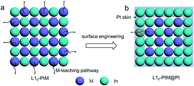
According to the crystal structure, Pt–M alloys can be divided into disordered phase (solid solution) and ordered phase (intermetallic compound). In disordered phases, the atomic positions are occupied randomly by Pt and M, so that they have varying surface compositions and randomly distributed active sites. In contrast, ordered Pt–M intermetallic compounds have well-defined stoichiometry and provide much better control of the local geometry of metal atoms, resulting in uniform distribution of active sites on the same surface plane. Recent studies show that transition metals in Pt-based intermetallic compounds exhibit desirable leaching tolerance under acidic conditions.21–23 It was found that the formal potential E0 (E0 is the potential measured in a half-cell relative to the standard hydrogen electrode, when the total concentration of each oxidation state is one formal;24E0 implies that the metal would leach into the electrolyte when the potential exceeds E0) of the transition metal in the intermetallic compound can be shifted to a higher value compared to that of pure transition metals due to the formation of an ordered phase with Pt, thus resulting in the enhanced leaching resistance.25 This can be explained by the correlation between the formation of free energy (ΔG0f) and ΔE0:
| ΔE0 = −ΔG0f/zF | (1) |
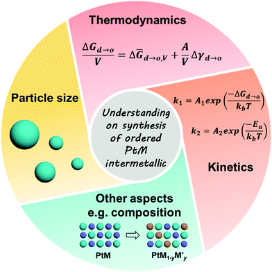
In addition to the desirable stability, the ordered PtM electrocatalysts also present impressive enhancement of the intrinsic electrocatalytic activity compared to their disordered counterparts.21 Given this, efforts have been made to developing highly active and stable PtM intermetallic electrocatalysts to meet the need for practical application in PEMFCs.28 To promote the atomic migration kinetically and ensure the formation of an ordered phase, high-temperature treatment of the disordered PtM alloy is generally an essential procedure for the synthesis of Pt-based intermetallic electrocatalysts. This treatment would also lead to the agglomeration of the ordered PtM nanoparticles (NPs). Nevertheless, a small particle size is vital for the high utilization of precious Pt in the electrocatalyst of PEMFCs because more Pt sites can be exposed in smaller particles. To this end, strategies have been employed to prevent the aggregation of the ordered PtM NPs during the annealing treatment, which narrows the particle sizes around 3 to 10 nm.23,31,32 Besides, due to the alternative arrangement of Pt and M at the surface of the ordered PtM NPs, the construction of much active surfaces like Pt skin is of great importance to facilitate their application on PEMFCs. Therefore, surface engineering of the ordered PtM NPs, like tuning the exposed facet and surface de-alloying, has been employed to construct a highly active surface to improve their electrocatalytic performance.33,34 Moreover, the surface strain effect of the ordered PtM NPs, which affects the shift of the d-band centre, could impact their ORR performance. Such a strain effect can be determined by the lattice mismatch or the ligand effect between the surface and the bulk component.11,12,35 By altering the composition of the PtM intermetallic NPs, the surface strain and electronic configuration can be adjusted to a much more beneficial state for electrocatalytic reactions.
The above-mentioned strategies such as “size control”, “surface engineering”, and “composition tuning” are general strategies used for optimizing the performance of ordered PtM NPs. This feature article overviews the strategies towards enhancing the electrocatalytic activity and stability of Pt-based intermetallic NPs. The enhancement mechanisms of these strategies are summarized in the corresponding sections. Finally, an outlook of electrocatalyst design for future development is provided.
2. Size control of Pt-based intermetallic NPs
2.1 Thermodynamic and kinetic understanding of the synthesis of intermetallic NPs
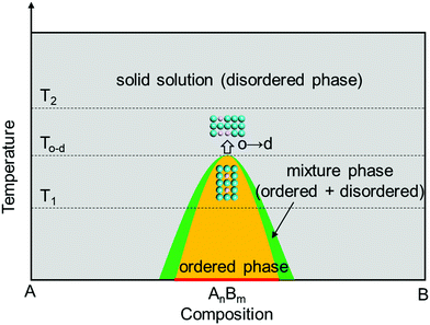
The formation conditions of the ordered phase for Pt-based intermetallics are crucial for their particle-size control. The thermodynamic and kinetic understanding of the formation mechanism for the intermetallic phase is highly beneficial for optimizing the synthesis conditions and realizing the size control strategy.| G = H − TS | (2) |
PtM intermetallics are usually synthesized by the heat treatment of the disordered PtM precursor. The difference of G between disordered and ordered PtM can be determined by eqn (3):
| ΔGd→o = ΔHd→o − TΔSd→o | (3) |
When the particle sizes were at nanoscale, their surface energy was non-negligible during the phase transition. Therefore, the free energy of the phase transition for nanocrystals can be denoted as eqn (4):
 | (4) |
 | (5) |
![[H with combining macron]](https://www.rsc.org/images/entities/i_char_0048_0304.gif) d→o,V (negative) and Δ
d→o,V (negative) and Δ![[S with combining macron]](https://www.rsc.org/images/entities/i_char_0053_0304.gif) d→o,V (negative) are the changes in specific volume enthalpy and entropy of the disorder-to-order transition, respectively. Within a certain system, the Δ
d→o,V (negative) are the changes in specific volume enthalpy and entropy of the disorder-to-order transition, respectively. Within a certain system, the Δ![[H with combining macron]](https://www.rsc.org/images/entities/i_char_0048_0304.gif) d→o,V, Δ
d→o,V, Δ![[S with combining macron]](https://www.rsc.org/images/entities/i_char_0053_0304.gif) d→o,V and Δγd→o are constant. As the
d→o,V and Δγd→o are constant. As the  value of the nanocrystal increases with its size decreasing, the lower temperature Td→o is beneficial for realizing the disorder-to-order phase transition in a smaller particle size system. For example, the ordering temperature of L10-PtCo NPs with a size of 2.4 to 3 nm could be achieved at 500 to 650 °C, respectively, which was 325 to 175 °C lower than that of the bulk L10-PtCo.37
 | (6) |
 | (7) |
For the synthesis of the ordered PtM electrocatalysts, smaller NPs can increase the utilization of Pt during electrocatalytic reactions and reduce the cost of PEMFCs as only the surface Pt atoms participate in the reaction. The above discussion of thermodynamic and kinetic perspective offers a basic understanding of how the synthesis conditions impact the preparation of ordered PtM NPs, which may have a better guideline for optimizing the synthesis of ordered PtM electrocatalysts.
2.2 Recent advances on size control of the ordered PtM NPs
As mentioned above, the synthesis of intermetallic compounds generally requires a high temperature heat treatment to improve the transition rate from the disordered phase to ordered phase (direct solution-phase synthesis is not discussed here), which leads to the agglomeration of NPs. Therefore, the intuitive way to control the particle size of intermetallic NPs is to employ protection during the annealing treatment so that the aggregation or sintering will be prevented. To this end, efforts have been made to achieve such a size control for the ordered PtM NPs.39–41Apart from the oxide coating, the porous carbon coating can also be utilized for maintaining the size of intermetallic NPs under thermal annealing. Heyeon's group coated the disordered FePt precursor with polydopamine in dopamine hydrochloride solution before thermal treatment.51 The as-formed polydopamine underwent a carbonization process at high temperature (e.g. 700 °C) and a thin N-doped carbon layer formed on the surface of metallic NPs as a result, which blocked the coalescence of FePt NPs when they were going through the phase transition from fcc to fct at 700 °C. The protected PtFe NPs maintained an unchanged size relative to that of the disordered PtFe precursor. In contrast, the PtFe without porous carbon coating protection sintered to tens of nanometres. It is worth noting that the thin N-doped carbon shell can be beneficial for the stability of the encapsulated intermetallic NPs in the long-term accelerated durability test (ADT) test and membrane assembly electrode (MEA) test due to the strong interactions between the N atom and surface Pt atom. Despite these impressive promotions, unfortunately, the carbon coating on the PtM NPs would inevitably cover the active sites of the electrocatalysts and further restrict the exposure of the active facet.
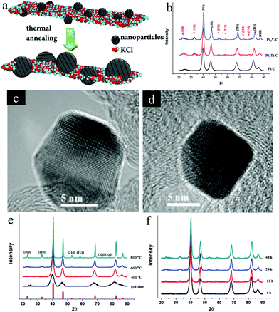 | ||
| Fig. 3 (a) Synthesis schematic of the ordered Pt3Fe by KCl matrix protection during the annealing treatment. Reproduced from ref. 40 with permission from American Chemical Society, Copyright 2012 (b) XRD patterns of Pt/C, Pt3Ti/C, and Pt3V/C: the superlattice diffraction peaks from the ordered structure are marked with *, (c and d) HR-TEM images of: (c) the ordered Pt3Ti/C and (d) the ordered Pt3V/C. Reproduced from ref. 54 with permission from American Chemical Society, Copyright 2014. (e) XRD patterns of the Pt3Cr/C at different annealing temperatures, (f) XRD patterns of Pt3Cr/C at 600 °C for different annealing times. Reproduced from ref. 14 with permission from American Chemical Society, Copyright 2015. | ||
Due to the low electronegativity, the early transition metal cations are difficult to be reduced by common methods. And the synthesized early transition metal–Pt intermetallic NPs generally suffered from the aggregation. To solve these issues, we employed KEt3BH to reduce metal salts of PtCl4 and TiCl4 or VCl3 along with the precipitation of KCl encapsulating the reduced Pt3Ti or Pt3V NPs.54 By adding the extra LiCl and KEt3BH in the surfactant-free synthesis process, the Pt3M@KCl (M = Ti, V) mixture was obtained. After annealing at 650–700 °C, ethylene glycol was used to remove the KCl and the remaining ordered Pt3M NPs were loaded on the carbon support. With the encapsulation of the KCl matrix, the ordered Pt3M NPs showed a small particle size around 6 nm. XRD patterns and HR-TEM images confirmed the specific superlattice in the obtained Pt3M intermetallics (Fig. 3b–d). During the electrocatalytic methanol oxidation test, both Pt3Ti/C and Pt3V/C showed much better performance than Pt/C.
Besides, the ordered Pt3Cr encapsulated with the KCl matrix was also employed to unveil how the annealing temperature and time affected the order degree and particle size of the synthesized Pt3Cr intermetallic in our later study.14 As shown in Fig. 3e, with an increasing temperature from 400 °C to 800 °C, the superlattice peaks of Pt3Cr NPs become sharper and the intensity of peaks became stronger, implying an increase of ordered degree and particle-size. As outlined in Fig. 3b, the superlattice peaks begin to appear after 12 h, and the intensity of the superlattice peaks increases with time and plateau after 24 h, which indicates that the long annealing time promotes the formation of the ordered structure but has no significant effect on the particle size. Based on the above investigations, an ordered Pt3Cr electrocatalyst with a NP size of ∼5 nm was successfully synthesised by annealing the Pt3Cr@KCl mixture at 600 °C for 48 h followed by removing the KCl. Compared with the disordered Pt–Cr alloy supported on carbon and Pt/C, the synthesized ordered Pt3Cr/C exhibited superior electrocatalytic activity and stability toward the ORR in acid media. The enhanced stability of the ordered Pt3Cr/C could be ascribed to the ordered structure of the Pt3Cr intermetallic. As revealed by the chemical stability test in 0.1 M HClO4 for four weeks, the Cr leaching amount of the ordered Pt3Cr was half of that of the disordered Pt3Cr and the ordered structure was preserved as suggested by the XRD result.
Considering the commercialization of the ordered PtM electrocatalysts, a scalable synthesis technique is highly indispensable to be developed by the researchers. Despite the achievements obtained on the development of synthesis methods for small ordered PtM NPs, there are rarely developed methods exhibiting scalability. To this end, we have recently developed a scalable and low-cost method based on the freeze dry and post thermal treatment technique for the synthesis of ordered PtM electrocatalysts.31,32 For instance, a nitrogen-doped mesoporous carbon (DMC) supported L12-Pt3Co electrocatalyst was synthesized by our recently developed impregnation-freeze drying-thermal reduction approach.31 The nitrogen-doped mesoporous carbon derived from ZIF-8 exhibited high specific surface area and abundant mesopores distributed in the narrow range of 2–4 nm, which was a desirable size for confining small NPs. By the freeze dry method, the Pt and Co precursors were homogeneously dispersed on the DMC support, followed by the heat treatment under a reducing atmosphere to obtain the ordered Pt3Co/DMC-F electrocatalyst (Fig. 4a). Due to the confinement effect of the mesopores, the reduced Pt3Co particle was well maintained at a small size (∼3 nm) without any sintering (Fig. 4b and c). In contrast, Pt3Co/C–F using commercial carbon as the support exhibited heavy agglomeration of the NPs (Fig. 4d). Particularly worth noting is that the freeze dry impregnation also played a crucial role in achieving small-size and homogeneous NPs. In such a freeze dry process, the solvent could be removed and would not change the highly dispersed and uniformly mixed state of the metal cations. This is beneficial to the growth of small PtM intermetallic NPs, while the traditional heat drying method inevitably causes the nonuniform element enrichment. As shown in Fig. 4e, the Pt3Co/DMC prepared by a conventional impregnation method rather than the freeze dry method exhibited a larger and inhomogeneous particle size. This was assumed to be the inhomogeneous or even separated distribution of Pt and Co precursors on the DMC support. By using such a porous carbon confinement and freeze dry impregnation method, the synthesized L12-Pt3Co/DMC-F showed much higher ORR performance than those of L12-Pt3Co/DMC or L12-Pt3Co/C-F and Pt/C (Fig. 4f). Besides, L12-Pt3Co/DMC-F only lost 13% of the mass activity after 5000 cycles, showing highly stable activity for long-term application, while that of Pt/C lost 40.6% (Fig. 4g). We also applied the L12-Pt3Co/DMC-F on the membrane assembled electrode (MEA, an electrode assessed on the PEMFC). As can be seen in Fig. 4h, the L12-Pt3Co/DMC-F-enabled MEA shows much better performance than that of Pt/C (Fig. 4h). The current density at 0.6 V of the L12-Pt3Co/DMC-F assembled MEA only decreased 15.4% after the 20![[thin space (1/6-em)]](https://www.rsc.org/images/entities/char_2009.gif) 000 cycle accelerated stress test (AST), while that of the Pt/C underwent a 15.8% deterioration after merely 10
000 cycle accelerated stress test (AST), while that of the Pt/C underwent a 15.8% deterioration after merely 10![[thin space (1/6-em)]](https://www.rsc.org/images/entities/char_2009.gif) 000 cycle AST, indicating the excellent durability of the L12-Pt3Co/DMC-F for practical application. Using such a freeze dry method, we also developed a general strategy for the synthesis of ultra-small L12-Pt3M (M = Mn, Fe, Co) NPs supported on reduced graphene oxide (rGO) aerogels or 3D hierarchical porous graphene. In this strategy, the metal precursors were first mixed with graphene oxide (GO) aqueous solution to form a homogeneous hydrogel, followed by a freeze dry treatment to obtain metal precursors (MPs)/GO aerogels (Fig. 5a). Different from the common drying method in an oven, this process could feasibly achieve good dispersion of metal precursors on GO support. The metal precursor impregnated GO hydrogel could transform to an aerogel with a 3D structure by handily avoiding the formation of liquid/vapor interface that can crush the 3D structure through a capillary pressure (Fig. 5b). After reducing the MPs/GO at high temperature, the sub-3 nm ordered Pt3M NPs supported on rGO (Pt3Mn/rGO-HF) were prepared. As can be seen in Fig. 5c, the ordered Pt3Mn NPs were well-dispersed on rGO support and sized at an average value of 2.8 nm. The as-prepared Pt3Mn/rGO-HF showed a high half-wave potential of 0.9 V, which surpasses those of the disordered Pt3Mn/rGO-HF and Pt/C with 20 mV and 50 mV, respectively. Such enhanced activity is assumed to be ascribed to the ordered structure and small particle size of Pt3Mn NPs. To investigate the reaction mechanism, the binding energies of the ORR intermediates (e.g. OOH*, O* and OH*) on the (111) facet of Pt and ordered Pt3Mn were calculated by density functional theory (DFT) calculations (Fig. 5d). It has been found that the energy barrier of the rate-determined step for Pt3Mn (ΔG2) is smaller than that of the pure Pt (ΔG4), which indicates a higher ORR reaction rate for Pt3Mn. As unveiled by the studies of Nørskov and his co-workers, the catalyst could have better ORR activity if it bounds O weaker than pure Pt.57,58 We have found that the Mn can modify the electronic structure of the surface Pt of Pt3Mn, which leads to the downshift of the d-band centre and weakens the binding to O.
000 cycle AST, indicating the excellent durability of the L12-Pt3Co/DMC-F for practical application. Using such a freeze dry method, we also developed a general strategy for the synthesis of ultra-small L12-Pt3M (M = Mn, Fe, Co) NPs supported on reduced graphene oxide (rGO) aerogels or 3D hierarchical porous graphene. In this strategy, the metal precursors were first mixed with graphene oxide (GO) aqueous solution to form a homogeneous hydrogel, followed by a freeze dry treatment to obtain metal precursors (MPs)/GO aerogels (Fig. 5a). Different from the common drying method in an oven, this process could feasibly achieve good dispersion of metal precursors on GO support. The metal precursor impregnated GO hydrogel could transform to an aerogel with a 3D structure by handily avoiding the formation of liquid/vapor interface that can crush the 3D structure through a capillary pressure (Fig. 5b). After reducing the MPs/GO at high temperature, the sub-3 nm ordered Pt3M NPs supported on rGO (Pt3Mn/rGO-HF) were prepared. As can be seen in Fig. 5c, the ordered Pt3Mn NPs were well-dispersed on rGO support and sized at an average value of 2.8 nm. The as-prepared Pt3Mn/rGO-HF showed a high half-wave potential of 0.9 V, which surpasses those of the disordered Pt3Mn/rGO-HF and Pt/C with 20 mV and 50 mV, respectively. Such enhanced activity is assumed to be ascribed to the ordered structure and small particle size of Pt3Mn NPs. To investigate the reaction mechanism, the binding energies of the ORR intermediates (e.g. OOH*, O* and OH*) on the (111) facet of Pt and ordered Pt3Mn were calculated by density functional theory (DFT) calculations (Fig. 5d). It has been found that the energy barrier of the rate-determined step for Pt3Mn (ΔG2) is smaller than that of the pure Pt (ΔG4), which indicates a higher ORR reaction rate for Pt3Mn. As unveiled by the studies of Nørskov and his co-workers, the catalyst could have better ORR activity if it bounds O weaker than pure Pt.57,58 We have found that the Mn can modify the electronic structure of the surface Pt of Pt3Mn, which leads to the downshift of the d-band centre and weakens the binding to O.
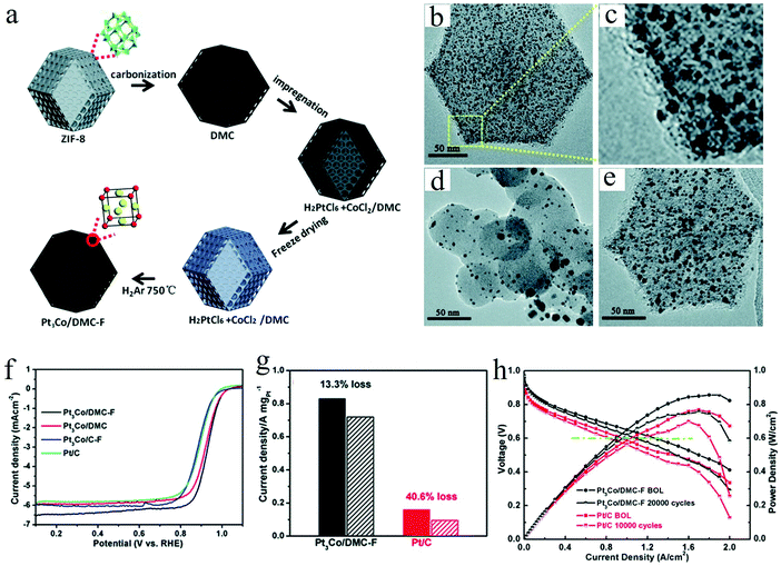 | ||
| Fig. 4 (a) Schematic of the preparation for Pt3Co NPs confined in MOF-derived mesoporous carbon via the freeze-dry impregnation and high temperature treatment method, TEM images of different Pt3Co electrocatalysts: (b and c) Pt3Co/DMC-F, (d) Pt3Co/C-F, and (e) Pt3Co/DMC, (f) the comparison of the ORR LSV curves between different electrocatalysts, (g) the comparison of the stability between Pt3Co/DMC-F and commercial Pt/C, (h) H2–air single cell polarization plots of the Pt3Co/DMC-F and the commercial Pt/C enabled MEAs, respectively, (c) bar graph of their PEMFC performance before and after AST test. Reproduced from ref. 31 with permission from Royal Society of Chemistry, Copyright 2020. | ||
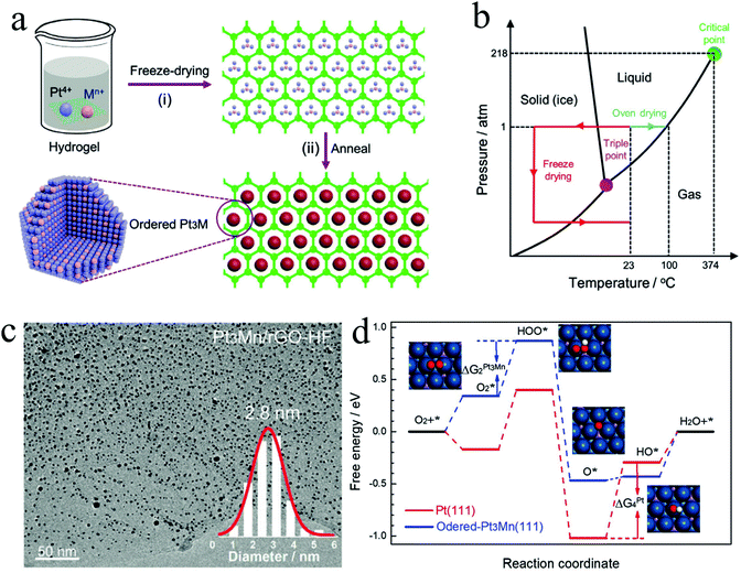 | ||
| Fig. 5 (a) Preparation scheme of ordered Pt3Mn/rGO-HF, (b) phase diagram of water, (c) TEM image of Pt3Mn/rGO-HF showing the ultra-small particle size of the synthesized ordered Pt3Mn, (d) the free energies of the intermediates along with the reaction on Pt(111) and ordered Pt3Mn(111) toward ORR. Reproduced from ref. 32 with permission from Wiley-VCH, Copyright 2020. | ||
3. Surface engineering of Pt-based intermetallic NPs
3.1 Rationality of surface engineering for ordered PtM electrocatalysts.
3.2 Recent advances on surface engineering of the ordered PtM NPs.
Driven by the need for developing a highly efficient electrocatalyst, efforts have been made to construct highly active and stable Pt skin on ordered PtM NPs. The recently reported surface engineering of the ordered PtM intermetallic is mainly focused on surface dealloying at the surface of the PtM intermetallic. The surface dealloying includes electrochemical dealloying and chemical dealloying, which is conducted by selective leaching of the surface M metal and stacking smooth Pt layers on the skin of the ordered PtM NPs.71 Besides, by controlling the growth conditions of the crystal in a wet-chemistry synthesis approach, a highly active Pt surface could also be formed on the ordered PtM nanostructure.60 In addition, the Pt segregation in some Pt–M systems during the annealing of the disordered PtM phase also can result in the formation of ordered PtM@Pt core–shell catalysts.72,73Abruña et al. employed a modified electrochemical dealloying method in N2-saturated 0.1 M HClO4 to construct a Pt shell on the ordered Cu3Pt NPs synthesized by an impregnation–reduction–annealing method.71,77 They applied the ordered Cu3Pt at 1.0 V for 3 h, the surface Cu dissolved sufficiently, and a highly active Pt skin was formed, resulting in a significant enhancement on the ORR activity (exceeds the Pt/C by a half-wave potential of 70 mV). They claimed that such enhanced performance was attributed to the largest surface area of the Pt shell and the surface strain induced by the ordered Pt–Cu core.
A similar electrochemical dealloying process was also conducted on ordered PtCo, PtCo3, Pt3Fe, PtFe, PtFe3, Pt2CoNi, and so on.59,63,78–80 The impact of such surface engineering on the ORR activity was impressive. Nevertheless, the generally reported methods of these electrochemical dealloying processes were carried out by using a three-electrode system, where a Pt wire or plate was used as the counter electrode. It has been widely accepted that Pt would dissolve from the Pt counter electrode into the electrolyte and then deposits on the working electrode during the long-term CV cycling, which could have an undesired impact on the electrocatalytic activity.81,82 Therefore, the authors of this articles recommend that an alternative counter electrode like graphite rod is more appropriate compared to the Pt electrode for electrochemical dealloying. Besides, since electrochemical dealloying is conducted on a fabricated electrode, it is technically difficult to scale up the preparation of the core–shell electrocatalyst, which hinders its widespread use.
![[thin space (1/6-em)]](https://www.rsc.org/images/entities/char_2009.gif) 000 cycle accelerated durability test (ADT). Such enhanced ORR activity and stability can be attributed to the construction of Pt skin on the ordered Pt3In NPs and the optimization of the oxygen binding energy by the intermetallic core.
000 cycle accelerated durability test (ADT). Such enhanced ORR activity and stability can be attributed to the construction of Pt skin on the ordered Pt3In NPs and the optimization of the oxygen binding energy by the intermetallic core.
Considering the utility of the developed catalysts, the durability test of the ORR catalysts under PEMFC operation conditions is essential to evaluate their durability for their application on PEMFCs. To this end, Sun and his co-workers immersed the as-prepared L10-PtFe intermetallic in 0.1 M HClO4 at 60 °C for 12 h to etch the surface Fe, and then followed by a heat treatment under a reduced atmosphere at 400 °C to form the core–shell L10-PtFe/Pt catalyst.41 They found that the electrocatalytic activity of the ordered PtFe intermetallic was quite unstable at 60 °C. The half-wave potential of the L10-PtFe decreased 36 mV after the 5000-cycle ADT at 60 °C, which is quite inferior compared to its stability at room temperature.63,78 By constructing a compact Pt skin on the surface of the core L10-PtFe, the ORR mass activity of L10-PtFe/Pt exhibits nearly no deterioration (lost 2.8% of 0.7 A mgPt−1) even after aging at 60 °C for 10![[thin space (1/6-em)]](https://www.rsc.org/images/entities/char_2009.gif) 000 cycles; while that of the commercial Pt/C lost 96% after the same ADT process. Moreover, the MEA fabricated with L10-PtFe/Pt showed highly stable performance after the ADT, which had met the DOE 2020 target (mass activity loss <40%).4 This strategy was also carried out to construct the L10-PtCo/Pt core–shell catalyst with excellent ORR activity and stability by the same group.33 After ADT at 60 °C for 30
000 cycles; while that of the commercial Pt/C lost 96% after the same ADT process. Moreover, the MEA fabricated with L10-PtFe/Pt showed highly stable performance after the ADT, which had met the DOE 2020 target (mass activity loss <40%).4 This strategy was also carried out to construct the L10-PtCo/Pt core–shell catalyst with excellent ORR activity and stability by the same group.33 After ADT at 60 °C for 30![[thin space (1/6-em)]](https://www.rsc.org/images/entities/char_2009.gif) 000 cycles, the mass activity of L10-PtCo/Pt only lost 18% of the initial (2.26 A mgPt−1). More importantly, the L10-PtCo/Pt exhibited an impressive mass activity of 0.56 A mgPt−1 in MEA measurement and only lost 19.6% of the mass activity after the 30
000 cycles, the mass activity of L10-PtCo/Pt only lost 18% of the initial (2.26 A mgPt−1). More importantly, the L10-PtCo/Pt exhibited an impressive mass activity of 0.56 A mgPt−1 in MEA measurement and only lost 19.6% of the mass activity after the 30![[thin space (1/6-em)]](https://www.rsc.org/images/entities/char_2009.gif) 000 cycle ADT test. Both of these results surpassed the DOE 2020 target (initial MEA mass activity: 0.44 A mgPt−1, MEA mass activity loss <40% after 30
000 cycle ADT test. Both of these results surpassed the DOE 2020 target (initial MEA mass activity: 0.44 A mgPt−1, MEA mass activity loss <40% after 30![[thin space (1/6-em)]](https://www.rsc.org/images/entities/char_2009.gif) 000 cycles).4 The performed DFT calculations revealed that a biaxial compressive strain (−4.50%/−4.25%) had been observed at the surface of L10-PtCo/Pt, which weakened the interaction between the absorbed intermediates and compressed Pt, promoting the ORR activity.
000 cycles).4 The performed DFT calculations revealed that a biaxial compressive strain (−4.50%/−4.25%) had been observed at the surface of L10-PtCo/Pt, which weakened the interaction between the absorbed intermediates and compressed Pt, promoting the ORR activity.
To better realize the surface engineering of the as-prepared ordered PtM NPs, chemical dealloying is a well-developed approach to be considered owing to its scalability and the derived favourable electrocatalytic performance. However, there is no need to perform extra surface dealloying during the synthesis of some ordered Pt–M systems as the highly active Pt surface can be constructed along with the formation of ordered PtM crystals.
Generally, the compressive strain of the surface Pt(111) facet is desirable for ORR performance by the optimization of adsorption energy.90,91 In contrast, a tensile Pt(111) is usually considered to be inconducive toward the ORR due to its very strong binding to the oxygen.34 However, in 2016, Huang et al. reported a biaxial-strain strategy combining tensile and compressive strains on the exposed Pt(110) facets of the PtPb/Pt core–shell hexagonal nanoplates, to impressively boost the ORR performance.34 They synthesized the intermetallic PtPb hexagonal nanoplates by a solution-phase method, where a Pt skin with a thickness of 0.8 to 1.2 nm was formed at the surface of the intermetallic PtPb nanoplates. As can be seen in Fig. 8a–d, there were two kinds of interfaces involving PtPb(010)//Pt(110) and PtPb(001)//Pt(110) on the top and edge of the hexagonal nanoplates. The lattice mismatch at these interfaces could induce both tensile and compressive strains along different directions at the surface of the nanoplates. In contrast to compressive strain (a negative strain), the tensile strain is a positive strain.92 The DFT calculations revealed that the large tensile strain of the exposed Pt(110) facet could help in optimizing the Pt–O bond strength. This couples with the compressive strain boosting the ORR performance. One year later, they employed a modified solution-phase method to synthesize intermetallic PtPb octahedra NPs and constructed a highly active PtNi shell on them.87 By such surface engineering, the tensile strain and the well-defined exposed facets of the PtNi shell enabled the developed PtPb@PtNi octahedra exhibiting excellent ORR performance with a mass activity of 1.92 A mgPt−1. Moreover, such a solution-phase synthesis of intermetallics was also extended to the synthesis of intermetallic Pt3Co with a hierarchical nanowire structure.60 The high-index (310) facet and (110) facet of the Pt3Co intermetallic nanowire were induced to be the exposed flat plates by adjusting the amount of the chemicals in the synthesis system, such as the amount of the CTAC surfactant, glucose reductant and Co(acac)2 salt. In this hierarchical structure, the three-fold hollow sites on the missing row reconstructed (310) facet and the (110) facet were found to be highly active toward the ORR with an optimized oxygen adsorption energy. The resultant ORR mass activity of Pt3Co was 33.7 times higher than that of the commercial Pt/C.
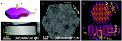 | ||
| Fig. 8 (a) A simulated 3D model of the PtPb/Pt core–shell hexagonal nanoplate, (b and c) the STEM/HAADF images of the PtPb/Pt hexagonal nanoplate from different directions marked in (a), (d) the simulated atomic arrangement in the top view and side view of the hexagonal nanoplate, presenting the facet interaction at the interfaces, the marked places of “D”, “E”, “F” correspondingly referring to the marked place in STEM/HAADF images of (b) and (c). Reproduced from ref. 34 with permission from American Association for the Advancement of Science, Copyright 2016. | ||
To date, the solution-phase preparation of the Pt-based intermetallic has been rarely reported. Despite the impressive scope of the surface engineering by solution-phase synthesis, efforts should be devoted to broadening its application to Pt–M systems. Besides, the scalability and cost of the solution-phase synthesis also necessitate the innovation of the synthesis technique(s) for better industrialization.
Héctor D. Abruña's group reported L12-Pt3Co@Pt core–shell catalysts where a Pt skin was formed on the surface of the core L12-Pt3Co after the annealing of the disordered Pt3Co at 700 °C for 2 h.72 Such Pt segregation along with the formation of the ordered phase enables the L12-Pt3Co@Pt presenting the ORR mass activity and specific activity superior to the disordered counterpart with over 200% and 300% enhancement, respectively. This enhanced ORR performance aroused by the Pt segregation in the L12-Pt3Co intermetallic also had been verified by our recent work on the sub-3 nm L12-Pt3Co NPs confined in the mesoporous carbon.31 In addition, it was found that the Pt segregation was also viable in the L10-PtCo electrocatalyst when the stoichiometry of Pt was slightly larger than that of Co.73 Moreover, Sung and his co-workers performed heat treatment on the as-prepared PtNi alloys at different temperatures in a reduced atmosphere of H2/Ar (5%/95%).98 They found that a Ni-rich surface could be obtained at 300 °C while a Pt skin was constructed at 700 °C along with the formation of ordered PtNi cores. The segregated Pt exposed a Pt(111) facet, which was verified to be highly active for the ORR performance.99,100 The ORR evaluation indicated a remarkable enhancement of the performance of the ordered PtNi@Pt (treated at 700 °C) compared to the disordered PtNi (treated at 300 °C).
Developing the PtM3 type intermetallic could significantly reduce the Pt content in the electrocatalyst compared to those of the Pt3M type and PtM type intermetallics. However, the content of the M metal in ordered PtM3 is high. This indicates that the M will become much easier to leach into the acid electrolyte and the durability issue will inhibit the application of PtM3. Recently, we have synthesized an ordered Fe3Pt electrocatalyst with a small NP size by annealing the disordered Fe3Pt under KCl matrix protection.101,102 As can be seen in Fig. 9a, the Pt (bright contrast) atom and Fe (dark contrast) atom were distributed with unique super periods, showing the ordered structure of the Fe3Pt intermetallic. The EDS line scan of an ordered Fe3Pt particle presented in Fig. 9b indicated a Pt skin formation. This was ascribed to the Pt segregation at the surface of the particle during high temperature treatment. Such a segregation effect has offered a highly active Pt skin on Fe3Pt NPs and effectively stabilized the inner Fe in acid media. The as-prepared ordered Fe3Pt was loaded onto a conventional carbon support (O-Fe3Pt/C) and a ternary transition metal support (O-Fe3Pt/Ti0.5Cr0.5N) to compare the ORR performance with the disordered one (D-Fe3Pt/C) and Pt/C. As can be seen in Fig. 9c, both O-Fe3Pt/C and O-Fe3Pt/Ti0.5Cr0.5N exhibit much higher mass activity than those of the D-Fe3Pt/C and Pt/C due to the highly active surface of the segregated Pt. The Pt skin also enabled high stability of the ORR activity for O-Fe3Pt/C and O-Fe3Pt/Ti0.5Cr0.5N. It is worth noting that the ternary transition metal nitride Ti0.5Cr0.5N can endow the O-Fe3Pt with higher activity and stability. Such an enhanced effect is mainly attributed to the excellent corrosion resistance of the Ti0.5Cr0.5N under high applied potentials and strong acid conditions.
 | ||
| Fig. 9 (a) HAADF/STEM image of an ordered Fe3Pt NP, (b) EDS line scan of an ordered Fe3Pt NP, (c) ORR mass activity of Pt/C, the disordered Fe3Pt/C, ordered Fe3Pt/C and ordered Fe3Pt/Ti0.5Cr0.5N. Reproduced from ref. 101 with permission from Wiley-VCH, Copyright 2019. | ||
4. Composition tuning of Pt-based Intermetallic NPs
4.1 Feasibility for the composition tuning of Pt-based Intermetallic NPs.
Previous studies had showed that the PtM intermetallic could preserve its pristine crystal structure when the originally involved metal was partially substituted by another suitable metal.103,104 Such composition flexibility can enable the optimization in their properties of the magnetism,105–107 lattice constant,108,109 electronic configuration,80 and surface strain.110–112 According to eqn (2) mentioned in Section 2, we can establish eqn (8) for calculating the free energy change between the transition of a binary PtMx intermetallic to a ternary PtMx−yM′y (0 < y < x) intermetallic:| ΔGb→t = ΔHb→t − TΔSb→t | (8) |
| ΔHb→t = εb − εt | (9) |
| ΔGb→t = (εb − εt) − TΔSb→t | (10) |
4.2 Recent advances on tuning the composition of Pt-based intermetallic electrocatalysts
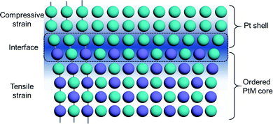
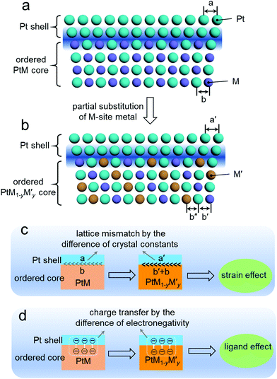
Fig. 10a and b show the schematic for the composition tuning of the ordered PtM@Pt catalyst by M-site metal substitution with another metal M′ to develop PtM1−yM′y@Pt. This composition tuning would exert a change on the lattice constants of the Pt shell and the ordered core. As mentioned in the surface engineering of Section 3, the strain effect at the surface Pt shell of the ordered PtM NPs would greatly impact their ORR performance. This surface strain is mainly attributed to the lattice mismatch at the interface between the surface Pt shell and the ordered PtM core.115 As illustrated in Fig. 10c, the difference of the lattice constants between the intermetallic core and Pt skin governs the lattice mismatch and further the strain effect. As such, altering the core composition of the ordered PtM@Pt electrocatalysts to govern the lattice mismatch should be a feasible way to optimize their electrocatalytic performance. When the thickness of the Pt shell is less than 0.6 nm, the ligand effect of the intermetallic core to the Pt shell is non-negligible.116 As can be seen in Fig. 10d, the ligand effect may lead to charge transferring from the core to the Pt shell. The tuning of the intermetallic core composition would change the electronegativity of the core metals, which governs their charge transfer to the Pt shell. Such a ligand effect of the surface Pt further exerts influence on its electronic configuration and further affects the adsorption energy to the intermediates of the electrocatalytic reaction.5,115 Therefore, composition tuning of Pt-based intermetallic electrocatalysts can enable the optimization of their surface strain and ligand effect, and further promote the electrocatalytic performance.In 2018, Wang et al. demonstrated a composition tuning strategy to promote the electrocatalysis of Pt-based intermetallics.112,117 They employed Cu to partially substitute the Fe in the L10-PtFe intermetallic, which resulted in a lower ordering temperature during the synthesis of L10-PtFexCu1−x.112 They found that with the substituted content of Cu increasing in L10-PtFexCu1−x, the lattice parameters gradually decreased along the c direction and increased along the a direction. This may be ascribed to the smaller atom radius of Cu compared to Fe, which caused the expansion of the unit cell along the c direction. Besides, it was found that the different compositions of the intermetallic core would alter the surface Pt–Pt distance, which could optimize its binding energy to intermediates and facilitate the electrocatalytic reaction. With a similar strategy, they also developed a group of L10-PtCo1−xNix (0 ≤ x < 1) electrocatalysts with various lattice parameters,117 which offered the optimization of the surface strain and electronic configuration for the L10-PtCo1−xNix NPs, and further promoted the electrocatalytic activity.
Recently, Li and his co-workers developed a ternary L10-PtCoNi intermetallic with a core–shell structure by a two-step approach (Fig. 11a).111 They found that the ternary intermetallic with a stoichiometry of PtNi0.8Co0.2 showed the best ORR performance among the developed L10-PtCoNi electrocatalysts, achieving a mass activity of 2.28 A mgPt−1. A constructed slab model shown in the inset in Fig. 11b was used to calculate the ΔE0 on the (111) facet of the pure Pt, L10-PtNi0.8Co0.2@Pt, L10-PtNi@Pt, and L10-PtCo@Pt as a function of the compressive strain. According to the linear plots illustrated in Fig. 11b, the optimal compressive strain for the ORR of the above models was calculated to be 2.1%, 1.29%, 1.53%, and 1.31%, respectively. After modelling a 5 nm core–shell NP for the pure Pt, L10-PtNi0.8Co0.2@Pt, L10-PtNi@Pt, and L10-PtCo@Pt, respectively, they calculated the strain distribution on the (111) facet of these models. As shown in Fig. 11c, remarkable compressive strain was observed at the surface of L10-PtNi0.8Co0.2@Pt, which was superior to that of the pure Pt. A microkinetic model was employed to calculate the ORR reaction rate on these electrocatalysts,118 the L10-PtNi0.8Co0.2@Pt presented the highest ORR rate among all the estimated catalysts, which is highly consistent with their electrochemical measurement results. Such enhanced activity of L10-PtNi0.8Co0.2@Pt can be ascribed to the optimized strain and ligand effects aroused by the composition tuning. In the same year, they used a modified method to synthesize the L10-W–PtCo@Pt core–shell catalyst, which was carried out under the strategy of composition tuning for the L10-PtCo electrocatalyst.50 The ORR performance on the half-cell test revealed that such composition tuning enabled a great enhancement of 1.04 A mgPt−1 on the mass activity of the L10-W–PtCo@Pt (2.21 A mgPt−1) compared to the L10-PtCo@Pt (1.17 A mgPt−1). More importantly, the L10-W–PtCo@Pt had also shown an impressive ORR performance in the MEA measurement, outperforming remarkably the commercial Pt/C catalyst (Fig. 11d). As can be seen in Fig. 11e, the initial mass activity of L10-W–PtCo@Pt (0.57 A mgPt−1) on the MEA at 0.9 V far exceeded that of the DOE 2020 target (0.44 A mgPt−1).4 This excellent performance only exhibited a slight deterioration (17.5%) after 30![[thin space (1/6-em)]](https://www.rsc.org/images/entities/char_2009.gif) 000 cycles, which is far below that of the DOE 2020 target (mass activity loss <40% after 30
000 cycles, which is far below that of the DOE 2020 target (mass activity loss <40% after 30![[thin space (1/6-em)]](https://www.rsc.org/images/entities/char_2009.gif) 000 cycles).4 By such a composition tuning strategy, a highly active and stable L10-W–PtCo@Pt/C electrocatalyst for the PEMFC was presented. The EXAFS and DFT calculation results had elucidated that the enhanced activity and stability could be ascribed to the optimized surface strain and the reduced surface energy on the Pt shell after tuning the composition.
000 cycles).4 By such a composition tuning strategy, a highly active and stable L10-W–PtCo@Pt/C electrocatalyst for the PEMFC was presented. The EXAFS and DFT calculation results had elucidated that the enhanced activity and stability could be ascribed to the optimized surface strain and the reduced surface energy on the Pt shell after tuning the composition.
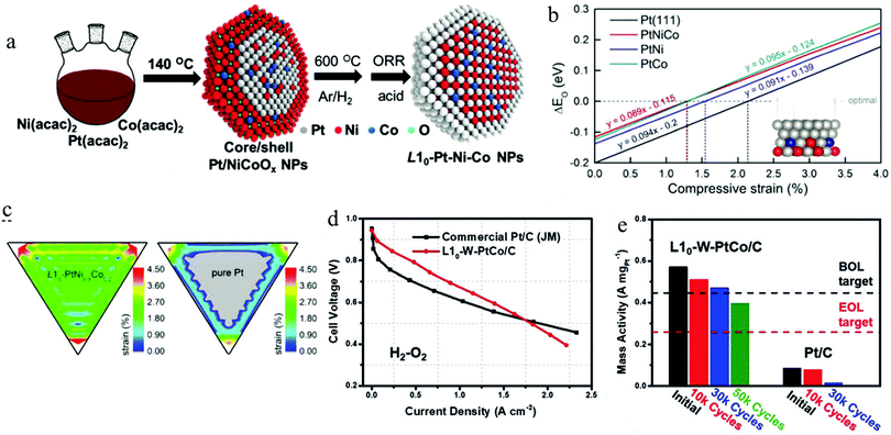 | ||
| Fig. 11 (a) The schematic of the preparation for ternary L10-Pt–Ni–Co@Pt core–shell NPs, (b) the difference (ΔE0) of the oxygen adsorption energy between the evaluated surfaces and an optimal value for the ORR as a function of compressive strain, (c) the compressive strain distribution of the (111) surface for L10-PtNi0.8Co0.2 and Pt NPs, the grey colour represents the tensile (negative) strain distributing area. Reproduced from ref. 111 with permission from Wiley-VCH, Copyright 2019. (d) The comparison of the H2–O2 PEMFC performance between commercial Pt/C and L10-W–PtCo/C catalysts, (e) the mass activity of the assembled MEA before and after different ADTs. Reproduced from ref. 50 with permission from Wiley-VCH, Copyright 2019. | ||
In addition to the above-mentioned advances, an Au doping strategy had also been employed to facilitate the formation of the ordered phase and promote the electrocatalytic activity for PtM intermetallics. In 2012, Sun's group reported ternary fct-FePtAu NPs by doping Au in FePt.119 They found that the presence of Au in a disordered fcc-FePtAu can induce the formation of the ordered fct-FePtAu during the annealing treatment. The electrocatalytic measurement indicated that the segregated Au at the surface of fct-FePtAu NPs facilitated the dehydrogenation of HCOOH during the formic acid oxidation reaction (FAOR), avoiding the generation of CO. This enhanced effect endows the fct-FePtAu NPs with highly active and stable performance on the electrocatalytic FAOR application. A similar effect had recently been applied on ternary L10-PtCoAu intermetallic NPs by the same group.110 The surface segregation of Au and Pt resulted in the formation of a PtAu alloy skin on the L10-PtCo core during the heat treatment. After such composition tuning, the derived L10-PtCoAu exhibited an outstanding electrocatalytic performance on some small molecule oxidation, including the electrocatalytic oxidation of ethanol, methanol, and formic acid. These impressive achievements were found to be ascribed to the synergistic effect by the compressed PtAu skin and the stabilized Co in the core, which facilitated the bond breaking of C–C/C–H in a non-CO route.
In brief, the composition tuning strategy of the intermetallic PtM electrocatalysts has gradually been verified as an effective way for promoting their electrocatalytic performance. Such a strategy coupled with the surface engineering can synergistically offer an optimization of the surface strain and electronic structure for better catalysing the electrocatalytic reaction.
5. Conclusions and perspectives
The development of Pt-based intermetallic electrocatalysts, with well-ordered structures, has been proven to be a promising route to meet the need for low Pt loading, high activity, and desirable durability of the electrocatalysts for PEMFC application. This feature article summarizes the recent advances on the enhancement strategies of the activity and stability for Pt-based intermetallic electrocatalysts, including the aspects of size control, surface engineering and composition tuning.Among the three strategies, the size control is the basic requirement for ordered PtM electrocatalysts and has attracted much research attention during the development history of ordered PtM electrocatalysts. Considering the final application of the ordered PtM intermetallics in the fuel cell popularization, the developed methods must be achievable from engineering perspective as well, particularly in large scale application.
Applying surface engineering to construct an ordered PtM@Pt core–shell structure with an ultrathin Pt skin is found to endow the ordered PtM@Pt with excellent electrocatalytic performance even under harsh operation conditions of PEMFCs due to the stabilization of the M by Pt skin and the induced surface strain. Such a strategy is the key section for achieving the popularization of the ordered PtM electrocatalysts in the PEMFC application.
The composition tuning strategy can lead to further optimization on the performance of the ordered PtM electrocatalysts, which is realized by the optimization of the surface strain, ligand effect and electronic structure. This new and promising strategy would offer great potential for promoting the electrocatalytic activity of the PtM intermetallic. Even so, some issues remain to be addressed in the future study due to its short development history. Systematic work on the theoretical investigation of composition tuning for Pt-based intermetallics is urgent to be carried out for better guiding the catalyst design. Besides, the diffusion behaviour of the multiple metals during thermal annealing and electrocatalytic reactions also need to be unveiled by advanced techniques to better understand the mechanism of component adjustment. What is more, tuning the composition may arouse the entropy increase of the system, which would lead to the ordered phase with more temperature-sensitive features.
In addition to these strategies, more tactics should be developed for intermetallic electrocatalysts to achieve a sustainable energy future. In retrospect of the development history for Pt-based electrocatalysts, they follow a trend from low dimension (zero dimension, NPs) to higher dimensions (dimension >0, e.g. nanowires, nanoplates, and nanoframes). In most cases, the Pt-based catalysts with higher-dimensional morphology would exhibit higher activity than the Pt-based NPs, as much active surface and more active sites can be exposed. Unfortunately, there is rarely reported Pt-based intermetallic with high-dimensional morphology rather than the NP morphology. Developing high-dimensional PtM intermetallics should be an alternative strategy for enhancing the electrocatalytic performance. What hinders this development should be the technical challenge of the synthesis. For a general synthesis, the disordered PtM precursor with a high-dimensional morphology will undergo a high temperature treatment to realize an ordered transition. This necessitates the robust protection of these nanostructures to preserve the morphology during the annealing process. Therefore, the development of the high-dimensional intermetallic electrocatalysts by a rational shape control will be a promising strategy for further enhancing the activity and stability of Pt-based intermetallic electrocatalysts.
In summary, for practical applications especially the automotive application, some challenges for Pt-based intermetallic catalysts still remain and their electrocatalytic performance needs to be further improved to meet the requirements of fuel cells. It is clear that more intensive research efforts should be made on the development of advanced strategies for the performance optimization of ordered intermetallic catalysts for fuel cell applications.
Conflicts of interest
There are no conflicts to declare.Acknowledgements
This work was supported by the Natural Science Foundation of Guangdong Province (2018A0303130239), the Science and Technology Program of Guangzhou (2019040146) and the Fundamental Research Funds for the Central Universities, SCUT.Notes and references
- X. X. Wang, M. T. Swihart and G. Wu, Nat. Catal., 2019, 2, 578–589 CrossRef CAS.
- M. M. Whiston, I. L. Azevedo, S. Litster, K. S. Whitefoot, C. Samaras and J. F. Whitacre, Proc. Natl. Acad. Sci. U. S. A., 2019, 116, 4899–4904 CrossRef CAS.
- B. G. Pollet, S. S. Kocha and I. Staffell, Curr. Opin. Electrochem., 2019, 16, 90–95 CrossRef CAS.
- D. Guo, R. Shibuya, C. Akiba, S. Saji, T. Kondo and J. Nakamura, Science, 2016, 351, 361–365 CrossRef CAS.
- J. Liang, F. Ma, S. Hwang, X. Wang, J. Sokolowski, Q. Li, G. Wu and D. Su, Joule, 2019, 3, 956–991 CrossRef CAS.
- Y. Wu, D. Wang, G. Zhou, R. Yu, C. Chen and Y. Li, J. Am. Chem. Soc., 2014, 136, 11594–11597 CrossRef CAS.
- B. Y. Xia, H. B. Wu, X. Wang and X. W. Lou, J. Am. Chem. Soc., 2012, 134, 13934–13937 CrossRef CAS.
- J. Zhang, L. Qu, G. Shi, J. Liu, J. Chen and L. Dai, Angew. Chem., 2016, 128(6), 2270–2274 CrossRef.
- M. Shao, J. H. Odell, A. Peles and D. Su, Chem. Commun., 2014, 50, 2173–2176 RSC.
- J. K. Norskov, F. Abild-Pedersen, F. Studt and T. Bligaard, Proc. Natl. Acad. Sci. U. S. A., 2011, 108, 937–943 CrossRef CAS.
- M. Mavrikakis, B. Hammer and J. K. Nørskov, Phys. Rev. Lett., 1998, 81, 2819–2822 CrossRef.
- A. Ruban, B. Hammer, P. Stoltze, H. L. Skriver and J. K. Nørskov, J. Mol. Catal. A: Chem., 1997, 115, 421–429 CrossRef CAS.
- X. Tian, X. Zhao, Y.-Q. Su, L. Wang, H. Wang, D. Dang, B. Chi, H. Liu, E. J. M. Hensen, X. W. D. Lou and B. Y. Xia, Science, 2019, 366, 850–856 CrossRef CAS.
- Z. Cui, H. Chen, W. Zhou, M. Zhao and F. J. DiSalvo, Chem. Mater., 2015, 27, 7538–7545 CrossRef CAS.
- I. E. L. Stephens, A. S. Bondarenko, U. Gronbjerg, J. Rossmeisl and I. Chorkendorff, Energy Environ. Sci., 2012, 5, 6744–6762 RSC.
- F. Maillard, L. Dubau, J. Durst, M. Chatenet, J. Andre and E. Rossinot, Electrochem. Commun., 2010, 12, 1161–1164 CrossRef CAS.
- J. Greeley and J. K. Nørskov, Electrochim. Acta, 2007, 52, 5829–5836 CrossRef CAS.
- R. Devivaraprasad, T. Kar, A. Chakraborty, R. K. Singh and M. Neergat, Phys. Chem. Chem. Phys., 2016, 18, 11220–11232 RSC.
- J. Li, M. Chen, D. A. Cullen, S. Hwang, M. Wang, B. Li, K. Liu, S. Karakalos, M. Lucero, H. Zhang, C. Lei, H. Xu, G. E. Sterbinsky, Z. Feng, D. Su, K. L. More, G. Wang, Z. Wang and G. Wu, Nat. Catal., 2018, 1, 935–945 CrossRef CAS.
- Y. Zhong, X. Liang, Z. He, W. Tan, J. Zhu, P. Yuan, R. Zhu and H. He, Appl. Catal., B, 2014, 150, 612–618 CrossRef.
- E. Antolini, Appl. Catal., B, 2017, 217, 201–213 CrossRef CAS.
- Y. Yan, J. S. Du, K. D. Gilroy, D. Yang, Y. Xia and H. Zhang, Adv. Mater., 2017, 29, 1605997 CrossRef.
- W. Xiao, W. Lei, M. Gong, H. L. Xin and D. Wang, ACS Catal., 2018, 8, 3237–3256 CrossRef CAS.
- R. A. Brown and E. H. Swift, J. Am. Chem. Soc., 1949, 71, 2719–2723 CrossRef CAS.
- G. Saravanan, K. Nanba, G. Kobayashi and F. Matsumoto, Electrochim. Acta, 2013, 99, 15–21 CrossRef CAS.
- D. R. Gaskell, Introduction to metallurgical thermodynamics, 1973 Search PubMed.
- A. R. Miedema, P. F. D. Chatel and F. R. D. Boer, Physica B+C, 1980, 100, 1–28 CrossRef CAS.
- J. Li and S. Sun, Acc. Chem. Res., 2019, 52, 2015–2025 CrossRef CAS.
- J. B. Staunton, S. Ostanin, S. S. A. Razee, B. L. Gyorffy, L. Szunyogh, B. Ginatempo and E. Bruno, Phys. Rev. Lett., 2004, 93, 257204 CrossRef CAS.
- T. Burkert, O. Eriksson, S. I. Simak, A. V. Ruban, B. Sanyal, L. Nordstrom and J. M. Wills, Phys. Rev. B: Condens. Matter Mater. Phys., 2005, 71, 134411 CrossRef.
- W. Zhao, Y. Ye, W. Jiang, J. Li, H. Tang, J. Hu, L. Du, Z. Cui and S. Liao, J. Mater. Chem. A, 2020, 8, 15822–15828 RSC.
- B. Zhang, G. Fu, Y. Li, L. Liang, N. S. Grundish, Y. Tang, J. B. Goodenough and Z. Cui, Angew. Chem., Int. Ed., 2020, 59, 7857–7863 CrossRef CAS.
- J. Li, S. Sharma, X. Liu, Y.-T. Pan, J. S. Spendelow, M. Chi, Y. Jia, P. Zhang, D. A. Cullen, Z. Xi, H. Lin, Z. Yin, B. Shen, M. Muzzio, C. Yu, Y. S. Kim, A. A. Peterson, K. L. More, H. Zhu and S. Sun, Joule, 2019, 3, 124–135 CrossRef CAS.
- L. Bu, N. Zhang, S. Guo, X. Zhang, J. Li, J. Yao, T. Wu, G. Lu, J. Y. Ma and D. Su, Science, 2016, 354, 1410–1414 CrossRef CAS.
- J. R. Kitchin, J. K. Norskov, M. A. Barteau and J. G. Chen, Phys. Rev. Lett., 2004, 93, 156801 CrossRef CAS.
- Y. Xiong, Y. Yang, H. Joress, E. Padgett, U. Gupta, V. Yarlagadda, D. N. Agyeman-Budu, X. Huang, T. E. Moylan, R. Zeng, A. Kongkanand, F. A. Escobedo, J. D. Brock, F. J. DiSalvo, D. A. Muller and H. D. Abruna, Proc. Natl. Acad. Sci. U. S. A., 2019, 116, 1974–1983 CrossRef CAS.
- D. Alloyeau, C. Ricolleau, C. Mottet, T. Oikawa, C. Langlois, Y. Le Bouar, N. Braidy and A. Loiseau, Nat. Mater., 2009, 8, 940–946 CrossRef CAS.
- A. Svante, Z. Phys. Chem., 1889, 4U, 96–116 Search PubMed.
- X. Ji, K. T. Lee, R. Holden, L. Zhang, J. Zhang, G. A. Botton, M. Couillard and L. F. Nazar, Nat. Chem., 2010, 2, 286–293 CrossRef CAS.
- H. Chen, D. Wang, Y. Yu, K. A. Newton, D. A. Muller, H. Abruña and F. J. DiSalvo, J. Am. Chem. Soc., 2012, 134, 18453–18459 CrossRef CAS.
- J. Li, Z. Xi, Y. T. Pan, J. S. Spendelow, P. N. Duchesne, D. Su, Q. Li, C. Yu, Z. Yin, B. Shen, Y. S. Kim, P. Zhang and S. Sun, J. Am. Chem. Soc., 2018, 140, 2926–2932 CrossRef CAS.
- Y. Takahashi, T. Kadono, S. Yamamoto, V. Singh, V. Verma, K. Ishigami, G. Shibata, T. Harano, Y. Takeda and T. Okane, Phys. Rev. B: Condens. Matter Mater. Phys., 2014, 90, 024423 CrossRef.
- D. C. Lee, F. V. Mikulec, J. M. Pelaez, B. Koo and B. A. Korgel, J. Phys. Chem. B, 2006, 110, 11160–11166 CrossRef CAS.
- S. Yamamoto, Y. Morimoto, T. Ono and M. Takano, Appl. Phys. Lett., 2005, 87, 032503 CrossRef.
- J. Kim, C. Rong, J. P. Liu and S. Sun, Adv. Mater., 2009, 21, 906–909 CrossRef CAS.
- J. Kim, Y. Lee and S. Sun, J. Am. Chem. Soc., 2010, 132, 4996–4997 CrossRef CAS.
- J. Kim, C. Rong, Y. Lee, J. P. Liu and S. Sun, Chem. Mater., 2008, 20, 7242–7245 CrossRef CAS.
- Z. Qi, C. Xiao, C. Liu, T. W. Goh, L. Zhou, R. Maligal-Ganesh, Y. Pei, X. Li, L. A. Curtiss and W. Huang, J. Am. Chem. Soc., 2017, 139, 4762–4768 CrossRef CAS.
- J. Kim, Y. Lee and S. Sun, J. Am. Chem. Soc., 2010, 132, 4996–4997 CrossRef CAS.
- J. Liang, N. Li, Z. Zhao, L. Ma, X. Wang, S. Li, X. Liu, T. Wang, Y. Du, G. Lu, J. Han, Y. Huang, D. Su and Q. Li, Angew. Chem., Int. Ed., 2019, 58, 15471–15477 CrossRef CAS.
- D. Y. Chung, S. W. Jun, G. Yoon, S. G. Kwon, D. Y. Shin, P. Seo, J. M. Yoo, H. Shin, Y. H. Chung, H. Kim, B. S. Mun, K. S. Lee, N. S. Lee, S. J. Yoo, D. H. Lim, K. Kang, Y. E. Sung and T. Hyeon, J. Am. Chem. Soc., 2015, 137, 15478–15485 CrossRef CAS.
- K. Elkins, D. Li, N. Poudyal, V. Nandwana, Z. Jin, K. Chen and J. P. Liu, J. Phys. D: Appl. Phys., 2005, 38, 2306–2309 CrossRef CAS.
- D. Li, N. Poudyal, V. Nandwana, Z. Jin, K. Elkins and J. P. Liu, J. Appl. Phys., 2006, 99, 08E911 CrossRef.
- Z. Cui, H. Chen, M. Zhao, D. Marshall, Y. Yu, H. Abruna and F. J. DiSalvo, J. Am. Chem. Soc., 2014, 136, 10206–10209 CrossRef CAS.
- I. C. Gerber and P. Serp, Chem. Rev., 2020, 120, 1250–1349 CrossRef CAS.
- B.-W. Zhang, C.-L. He, Y.-X. Jiang, M.-H. Chen, Y.-Y. Li, L. Rao and S.-G. Sun, Electrochem. Commun., 2012, 25, 105–108 CrossRef CAS.
- J. Greeley, I. Stephens, A. Bondarenko, T. Johansson, H. Hansen and T. Jaramillo, Nat. Chem., 2009, 1, 552–556 CrossRef CAS.
- V. Stamenkovic, B. S. Mun, K. J. Mayrhofer, P. N. Ross, N. M. Markovic, J. Rossmeisl, J. Greeley and J. K. Nørskov, Angew. Chem., Int. Ed., 2006, 118, 2963–2967 CrossRef.
- Z. Liu, G. S. Jackson and B. W. Eichhorn, Energy Environ. Sci., 2011, 4, 1900–1903 RSC.
- L. Bu, S. Guo, X. Zhang, X. Shen, D. Su, G. Lu, X. Zhu, J. Yao, J. Guo and X. Huang, Nat. Commun., 2016, 7, 11850 CrossRef CAS.
- C. Chen, Y. Kang, Z. Huo, Z. Zhu, W. Huang, H. L. Xin, J. D. Snyder, D. Li, J. A. Herron, M. Mavrikakis, M. Chi, K. L. More, Y. Li, N. M. Markovic, G. A. Somorjai, P. Yang and V. R. Stamenkovic, Science, 2014, 343, 1339–1343 CrossRef CAS.
- V. R. Stamenkovic, B. Fowler, B. S. Mun, G. Wang, P. N. Ross, C. A. Lucas and N. M. Markovic, Science, 2007, 315, 493–497 CrossRef CAS.
- Y. Hu, J. O. Jensen, W. Zhang, L. N. Cleemann, W. Xing, N. J. Bjerrum and Q. Li, Angew. Chem., Int. Ed., 2014, 53, 3675–3679 CrossRef CAS.
- E. Christoffersen, P. Liu, A. Ruban, H. L. Skriver and J. K. Nørskov, J. Catal., 2001, 199, 123–131 CrossRef CAS.
- J. Zhang, L. Zhang, L. Du, H. L. Xin, J. B. Goodenough and Z. Cui, Angew. Chem., Int. Ed., 2020, 132, 17641–17646 CrossRef.
- E. J. Coleman, M. H. Chowdhury and A. C. Co, ACS Catal., 2015, 5, 1245–1253 CrossRef CAS.
- Y.-J. Wang, W. Long, L. Wang, R. Yuan, A. Ignaszak, B. Fang and D. P. Wilkinson, Energy Environ. Sci., 2018, 11, 258–275 RSC.
- G. Wang, Z. Yang, Y. Du and Y. Yang, Angew. Chem., Int. Ed., 2019, 58, 15848–15854 CrossRef CAS.
- M. Luo, Y. Sun, X. Zhang, Y. Qin, M. Li, Y. Li, C. Li, Y. Yang, L. Wang, P. Gao, G. Lu and S. Guo, Adv. Mater., 2018, 30(10), 1705515 CrossRef.
- X. Wu, Y. Jiang, Y. Yan, X. Li, S. Luo, J. Huang, J. Li, R. Shen, D. Yang and H. Zhang, Adv. Sci., 2019, 6, 1902249 CrossRef CAS.
- D. Wang, Y. Yu, H. L. Xin, R. Hovden, P. Ercius, J. A. Mundy, H. Chen, J. H. Richard, D. A. Muller, F. J. DiSalvo and H. D. Abruna, Nano Lett., 2012, 12, 5230–5238 CrossRef CAS.
- D. Wang, H. L. Xin, R. Hovden, H. Wang, Y. Yu, D. A. Muller, F. J. DiSalvo and H. D. Abruña, Nat. Mater., 2013, 12, 81–87 CrossRef CAS.
- W. Yang, L. Zou, Q. Huang, Z. Zou, Y. Hu and H. Yang, J. Electrochem. Soc., 2017, 164, H331–H337 CrossRef CAS.
- M. Neergat and R. Rahul, J. Electrochem. Soc., 2012, 159, F234–F241 CrossRef CAS.
- Z. Liu, G. S. Jackson and B. W. Eichhorn, Angew. Chem., Int. Ed., 2010, 49, 3173–3176 CrossRef CAS.
- B. Hammer, Y. Morikawa and J. K. Nørskov, Phys. Rev. Lett., 1996, 76, 2141–2144 CrossRef CAS.
- D. Wang, Y. Yu, J. Zhu, S. Liu, D. A. Muller and H. D. Abruna, Nano Lett., 2015, 15, 1343–1348 CrossRef CAS.
- Q. Li, L. Wu, G. Wu, D. Su, H. Lv, S. Zhang, W. Zhu, A. Casimir, H. Zhu, A. Mendoza-Garcia and S. Sun, Nano Lett., 2015, 15, 2468–2473 CrossRef CAS.
- Z. Wang, X. Yao, Y. Kang, L. Miao, D. Xia and L. Gan, Adv. Funct. Mater., 2019, 29, 1902987 CrossRef.
- M. Lokanathan, I. M. Patil, M. Navaneethan, V. Parey, R. Thapa and B. Kakade, Nano Energy, 2018, 43, 219–227 CrossRef CAS.
- R. Chen, C. Yang, W. Cai, H.-Y. Wang, J. Miao, L. Zhang, S. Chen and B. Liu, ACS Energy Lett., 2017, 2, 1070–1075 CrossRef CAS.
- J. Zhang, Y. Zhao, X. Guo, C. Chen, C.-L. Dong, R.-S. Liu, C.-P. Han, Y. Li, Y. Gogotsi and G. Wang, Nat. Catal., 2018, 1, 985–992 CrossRef CAS.
- Q. Wang, Z. L. Zhao, Z. Zhang, T. Feng, R. Zhong, H. Xu, S. T. Pantelides and M. Gu, Adv. Sci., 2019, 7, 1901279 CrossRef.
- C. Wang, D. P. Chen, X. Sang, R. R. Unocic and S. E. Skrabalak, ACS Nano, 2016, 10, 6345–6353 CrossRef CAS.
- R. Devivaraprasad, N. Nalajala, B. Bera and M. Neergat, Front. Chem., 2019, 7, 648 CrossRef CAS.
- W. Lei, J. Xu, Y. Yu, W. Yang, Y. Hou and D. Chen, Nano Lett., 2018, 18, 7839–7844 CrossRef CAS.
- L. Bu, Q. Shao, E. Bin, J. Guo, J. Yao and X. Huang, J. Am. Chem. Soc., 2017, 139, 9576–9582 CrossRef CAS.
- H. Wang, P. Shang, J. Zhang, M. Guo, Y. Mu, Q. Li and H. Wang, Chem. Mater., 2013, 25, 2450–2454 CrossRef CAS.
- Y. Yu, P. Mukherjee, Y. Tian, X. Z. Li, J. E. Shield and D. J. Sellmyer, Nanoscale, 2014, 6, 12050–12055 RSC.
- H. Yang, J. Zhang, K. Sun, S. Zou and J. Fang, Angew. Chem., Int. Ed., 2010, 49, 6848–6851 CrossRef CAS.
- J. Zhang, H. Yang, J. Fang and S. Zou, Nano Lett., 2010, 10, 638–644 CrossRef CAS.
- K. Kusagaya, H. Hagino, S. Tanaka, K. Miyazaki and M. Takashiri, J. Electron. Mater., 2014, 44, 1632–1636 CrossRef.
- A. V. Ruban, H. L. Skriver and J. K. Nørskov, Phys. Rev. B: Condens. Matter Mater. Phys., 1999, 59, 15990–16000 CrossRef.
- M. Chi, C. Wang, Y. Lei, G. Wang, D. Li, K. L. More, A. Lupini, L. F. Allard, N. M. Markovic and V. R. Stamenkovic, Nat. Commun., 2015, 6, 8925 CrossRef CAS.
- L. Gan, M. Heggen, C. Cui and P. Strasser, ACS Catal., 2015, 6, 692–695 CrossRef.
- P. Andreazza, V. Pierron-Bohnes, F. Tournus, C. Andreazza-Vignolle and V. Dupuis, Surf. Sci. Rep., 2015, 70, 188–258 CrossRef CAS.
- A. Front, B. Legrand, G. Tréglia and C. Mottet, Surf. Sci., 2019, 679, 128–138 CrossRef CAS.
- Y.-H. Chung, D. Y. Chung, N. Jung, H. Y. Park, S. J. Yoo, J. H. Jang and Y.-E. Sung, J. Phys. Chem. C, 2014, 118, 9939–9945 CrossRef CAS.
- Y. Bing, H. Liu, L. Zhang, D. Ghosh and J. Zhang, Chem. Soc. Rev., 2010, 39, 2184–2202 RSC.
- H. Liao, A. Fisher and Z. J. Xu, Small, 2015, 11, 3221–3246 CrossRef CAS.
- Q. Liu, L. Du, G. Fu, Z. Cui, Y. Li, D. Dang, X. Gao, Q. Zheng and J. B. Goodenough, Adv. Energy Mater., 2019, 9, 1803040 CrossRef.
- Z. Cui, G. Fu, Y. Li and J. B. Goodenough, Angew. Chem., Int. Ed., 2017, 56, 9901–9905 CrossRef CAS.
- J. C. Woolley and B. Bates, J. Less-Common Met., 1959, 1, 382–389 CrossRef CAS.
- J. C. Woolley and B. Bates, J. Less-Common Met., 1960, 2, 11–18 CrossRef CAS.
- T. H. Kim, M. C. Cadeville, A. Dinia, V. Pierron-Bohnes and H. Rakoto, Phys. Rev. B: Condens. Matter Mater. Phys., 1996, 54, 3408–3419 CrossRef CAS.
- Q. Yan, T. Kim, A. Purkayastha, P. G. Ganesan, M. Shima and G. Ramanath, Adv. Mater., 2005, 17, 2233–2237 CrossRef CAS.
- Q. Y. Yan, T. Kim, A. Purkayastha, Y. Xu, M. Shima, R. J. Gambino and G. Ramanath, J. Appl. Phys., 2006, 99, 08N709 CrossRef.
- H. W. Ryu, K. Sato and Y. Hirotsu, Mater. Trans., 2007, 48, 903–908 CrossRef CAS.
- H.-W. Yang, C.-M. Chung and J. Y. Ding, J. Magn. Magn. Mater., 2007, 312, 239–244 CrossRef CAS.
- J. Li, S. Z. Jilani, H. Lin, X. Liu, K. Wei, Y. Jia, P. Zhang, M. Chi, Y. J. Tong, Z. Xi and S. Sun, Angew. Chem., Int. Ed., 2019, 58, 11527–11533 CrossRef CAS.
- T. Wang, J. Liang, Z. Zhao, S. Li, G. Lu, Z. Xia, C. Wang, J. Luo, J. Han, C. Ma, Y. Huang and Q. Li, Adv. Energy Mater., 2019, 9, 1803771 CrossRef.
- J. Zhu, Y. Yang, L. Chen, W. Xiao, H. Liu, H. D. Abruña and D. Wang, Chem. Mater., 2018, 30, 5987–5995 CrossRef CAS.
- D. A. Porter, K. E. Easterling and M. Sherif, Phase transformations in metals and alloys (revised reprint), CRC Press, 2009 Search PubMed.
- J. W. Mullin, Crystallization, Elsevier, 2001 Search PubMed.
- M. Luo and S. Guo, Nat. Rev. Mater., 2017, 2, 17059 CrossRef CAS.
- X. Zhang and G. Lu, J. Phys. Chem. Lett., 2014, 5, 292–297 CrossRef CAS.
- L. Chen, J. Zhu, C. Xuan, W. Xiao, K. Xia, W. Xia, C. Lai, H. L. Xin and D. Wang, J. Mater. Chem. A, 2018, 6, 5848–5855 RSC.
- J. K. Nørskov, J. Rossmeisl, A. Logadottir and L. Lindqvist, J. Phys. Chem. B, 2004, 108, 17886–17892 CrossRef.
- S. Zhang, S. Guo, H. Zhu, D. Su and S. Sun, J. Am. Chem. Soc., 2012, 134, 5060–5063 CrossRef CAS.
Footnote |
| † These authors contributed equally to this feature article. |
| This journal is © The Royal Society of Chemistry 2021 |


