
Temporally resolved thermal desorption of volatile organics from nanoporous silica preconcentrator†
William
Winter‡
a,
Coco
Day‡
 b,
Joshua
Prestage
a and
Tanya
Hutter
*ac
b,
Joshua
Prestage
a and
Tanya
Hutter
*ac
aSensorHut Ltd, Cambridge, UK. E-mail: tanya.hutter@utexas.edu
bDepartment of Chemistry, University of Cambridge, Lensfield Road, Cambridge CB2 1EW, UK
cDepartment of Mechanical Engineering, Materials Science and Engineering Program and Texas Materials Institute, The University of Texas at Austin, Austin, TX 78712, USA
First published on 3rd November 2020
Abstract
Detection and separation of gas-phase volatile organic compounds (VOCs) is of great importance for many applications including air quality monitoring, toxic gas detection and medical diagnostics. A lack of small and low-cost detectors limits the potential applications of VOC gas sensors, especially in the areas of consumer products and the ‘Internet of Things’. Most of the commercially available low-cost technologies are either only capable of measuring a single VOC type, or only provide a total VOC concentration, without the ability to provide information on the nature or type of the VOC. We present a new approach for improving the selectivity of VOC detection, based on temporally resolved thermal desorption of VOCs from a nanoporous material, which can be combined with any existing VOC detector. This work uses a nanoporous silica material that adsorbs VOC molecules, which are then thermally desorbed onto a broadband VOC detector. Different VOCs are desorbed at different temperatures depending on their boiling point and affinity to the porous surface. The nanoporous silica is inert; VOC adsorption is proportional to the concentration of VOC in the environment, and is fully reversible. An example of a detection system using a commercial total VOC photoionization detector and a nanoporous silica preconcentrator is demonstrated here for six different VOCs, and shows potential for discrimination between the VOCs.
Introduction
Volatile organic compounds (VOCs) are ubiquitous: they are produced by a huge variety of processes, both natural and industrial, all around the globe. Their gas-phase concentrations in the air can range over several orders of magnitude, and their structures and properties vary hugely. Many of them have significant impacts on human life or the environment: VOCs from industry or transport pollution can be damaging to health,1 while traces of explosive VOCs in the air can be used for explosives detection, and the VOCs produced by patients can be used in medical diagnostics.2,3However, such VOCs are often present at parts-per-trillion (ppt) or parts-per-billion (ppb) concentrations, so achieving accurate detection is difficult. Another challenge is that many of the VOCs that are present in the environment are very similar in structure and properties, making selective detection both important and difficult to achieve.4 The current methods for detecting VOCs are many and varied to fit their different applications. Some of the most common low-cost and small detectors are based on non-dispersive infrared (NDIR), metal oxides (MOx), electrochemical and photoionization detectors (PIDs). However, portable and affordable sensors rarely achieve low enough limits of detection or are suitably selective for a particular VOC and suffer from cross-sensitivity, baseline drifts and poisoning.4
As an answer to this problem, a significant amount of work has been done on developing preconcentrators based on adsorbent materials, often porous, to enhance the sensitivity and selectivity of VOC sensors.5 These generally work by adsorbing VOCs over a certain amount of time, before releasing them after a trigger event, which is most often a sharp increase in temperature. The instantaneous concentration of the VOC after this release is higher than the initial concentration present, and therefore the gas detector to which it is connected registers a momentarily higher response. Temperature homogeneity in both lateral and vertical directions, and good heat transfer, are important for ensuring that the desorption of analyte from the entire preconcentrator occurs simultaneously, resulting in a sharp peak measured by the detector.
Several existing preconcentrators for VOC detection in the literature are based on metal–oxide frameworks (MOFs), the structure of which contains small pores and which have been used, amongst other applications, for detection of benzene6,7 and formaldehyde.8 The detection of these two gases is some of the most widely researched, as both are present in many situations and harmful to human health.4 Other common preconcentrator materials are carbon-based; thanks to their large adsorption capacity, they have also been used as preconcentrators for detection of atmospheric pollutants such as benzene and butadiene.9 Carbon-based materials are often present as powders and must be contained within a scaffold. Porous silicon has been used as a scaffold for a carbon-based filler for improving the detection of benzene10 and nitrobenzene (with a view to detection of nitroaromatic explosives).11
Only a few preconcentrators have been developed with micro-machined silicon itself as the concentrating material without a filler, including ones for breath analysis,12 acetone13 and nitroaromatic explosives.14 However, all these examples of preconcentration in the literature seem to involve a rapid desorption event to release all the adsorbed VOC at once, causing the highest possible instantaneous concentration. Leidinger et al. have reported a temperature-modulated operation of metal oxide semiconductor sensors for detection of different VOCs. They found that the varying temperature profile led to different sensor response profiles for different VOCs.15 However, this temperature modulation was done on the sensor itself, and at high temperatures of 200 °C to 400 °C; no work appears to have yet been done on slowly desorbing accumulated VOCs from a preconcentrator and investigating the response of the gas detector to different VOCs as a function of the increasing temperature.
Here we introduce a method of potentially enhancing the selectivity of low-cost VOC detectors using a nanoporous preconcentrator by slowly increasing the temperature in a controlled manner while recording detector response. The nanoporous material used in this study consists of a mesoporous silica layer on a silicon wafer, which is simple to fabricate.16 For VOC detection, a commercially available broadband VOC photoionization detector (PID) was used. The temperature of the porous material is first lowered to enhance the adsorption of VOCs from a gas flow into the nanopores. The temperature is then raised steadily at a constant rate to desorb the VOCs, causing a peak in VOC concentration which is detected by the PID. The time of the peak from the start of heating, and the shape of the peak, are characteristic to each VOC. This work focusses on the study of adsorption and desorption of different VOCs from nanoporous silica, and shows how the properties of the VOC and its affinity to the surface play an important role in the ability to achieve temporally separated thermal desorption.
Experimental
A nanoporous silica layer with a diameter of 15 mm was fabricated on a boron-doped silicon wafer with a resistivity of 0.01–0.02 Ω cm and <100> crystal orientation. The silicon wafer was electrochemically etched in 1![[thin space (1/6-em)]](https://www.rsc.org/images/entities/char_2009.gif) :1 mixture of 48% hydrofluoric acid and ethanol under a current density of 120 mA cm−2. The current was applied cyclically – on for 2 s, off for 3 s – with 144 repeats. The sample was then thermally oxidized under an O2 flow of 10 sccm at 400 °C for 60 min and then at 800 °C for 16 hours. This oxidation procedure is carried out to improve stability; an uncontrolled native oxide layer would otherwise form on the surface of the silicon.
:1 mixture of 48% hydrofluoric acid and ethanol under a current density of 120 mA cm−2. The current was applied cyclically – on for 2 s, off for 3 s – with 144 repeats. The sample was then thermally oxidized under an O2 flow of 10 sccm at 400 °C for 60 min and then at 800 °C for 16 hours. This oxidation procedure is carried out to improve stability; an uncontrolled native oxide layer would otherwise form on the surface of the silicon.
Scanning electron microscopy (SEM) top-view and cross-section images of the nanoporous silica sample are shown in Fig. 1. From the top-view image in Fig. 1a, it can be seen that the features are below 50 nm. The cross-sectional image in Fig. 1b shows the morphology of the porous network, and Fig. 1c shows the thickness of the porous layer, which is 32.3 μm.
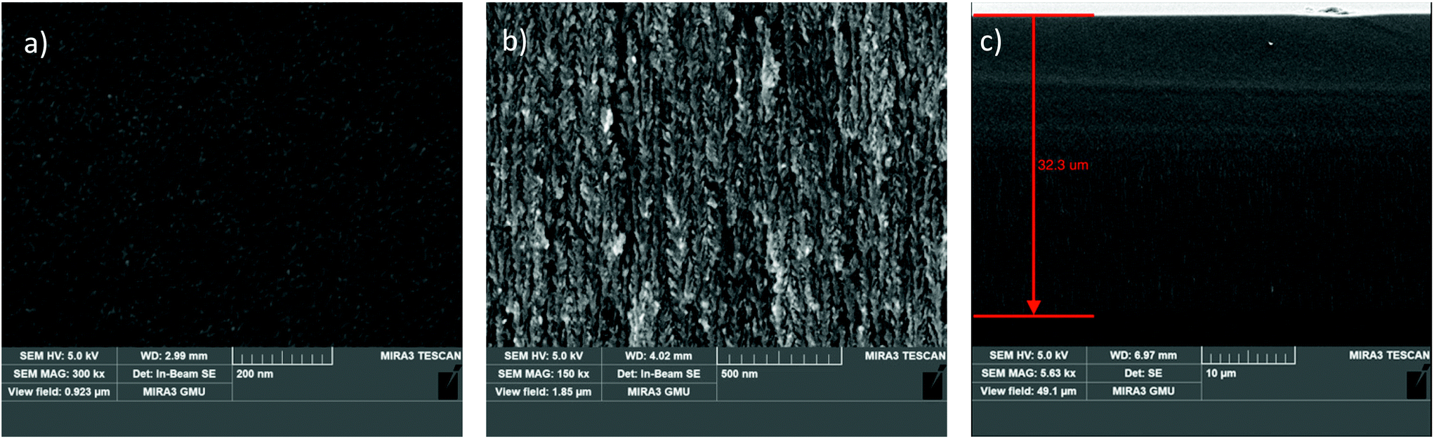 | ||
| Fig. 1 (a) SEM top-view image of porous silica. (b) SEM cross-sectional image of the porous network. (c) SEM cross-section showing the thickness of the porous layer. | ||
Brunauer–Emmett–Teller (BET) adsorption isotherm analysis (3Flex analyser, Micromeritics) was performed to determine the surface area per gram of the sample, and found it to be 120.4 m2 g−1. The Barrett–Joyner–Halenda (BJH) adsorption pore size distribution gave the average pore diameter as 23 nm, which is classified as mesoporous silicon by IUPAC. The pore size distribution is shown in Fig. S1 in the ESI.†
A commercially available 10.6 eV photoionisation detector (PID-AH, Alphasense, UK) was assembled with the nanoporous silica in a custom-built PEEK gas-flow cell. The temperature was set using a Peltier thermoelectric module (ETC-031-14-11-E, European Thermodynamics Ltd) and controlled using a direct current control module (TEC-1091, Meerstetter Engineering, Switzerland). The temperature range of the Peltier module is 5 °C to 70 °C, with a maximum temperature ramp rate of 30 °C min−1. The nanoporous silica is connected to the Peltier by a thermally conducting rubber sheet, to ensure good heat transfer. A schematic diagram of the sensor device assembly, which includes the nanoporous silica, Peltier, heat sink, gas cell and PID, is shown in Fig. 2a and a photo of the device in Fig. 2b. The overall dimensions of the assembly are 60 mm × 60 mm × 45 mm, and the internal volume of the flow cell is approximately 1 mL.
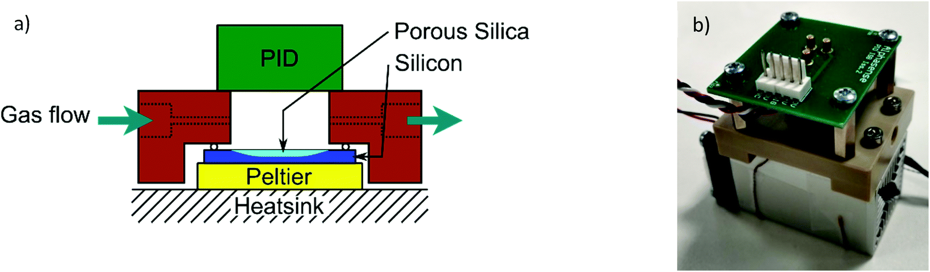 | ||
| Fig. 2 (a) Schematic diagram of the sensor assembly. (b) Photo of the sensor assembly. | ||
The photoionisation detector (PID) works by ionising VOC molecules inside its chamber. The VOCs that are ionised have ionisation energy less than or equal to that of the photon energy of its lamp (10.6 eV in this case); these ions interact with electrodes inside the chamber to produce an electrical voltage, which is the output of the PID. This voltage is proportional to VOC concentration, and the constant of proportionality is different for different VOCs. The PID operates at a rate of one voltage measurement taken every 2 s.
High purity nitrogen gas (N2 99.9995% BOC, UK) was used as a carrier gas for the experiments. A commercially available permeation tube VOC generator, V-OVG (Owlstone, UK) which can accurately generate different VOC concentrations was used to generate the VOC gases. The V-OVG has an internal temperature controller which maintains a PTFE permeation tube at a fixed temperature and therefore at a fixed permeation rate. The permeation rates for the different VOCs are measured gravimetrically. One internal mass-flow controller (MFC) and one external MFC allow the total flow through the V-OVG, and hence the concentration of the VOC, to be set. Part of this gas is then diluted with a second flow of nitrogen. The desired flow rate of this diluted gas passes through a MFC while the excess is rejected via a pressure regulator. Finally, a rotary valve is used allow the flow through the cell to be switched between the diluted VOC-carrying gas and another stream of pure nitrogen. The gas setup used in this study is shown in Fig. S2 in the ESI.† The flow rate over the sample was kept constant at 50 mL min−1.
Results and discussion
Measurement principle
The quantity of VOC that is adsorbed in the pores is expected to be dependent on a variety of factors. These include the surface area of the nanoporous silica, the length of time for which the VOC is allowed to accumulate, the temperature of the silica, the concentration of the VOC to which it is exposed and the surface interactions between the porous silica and the VOC. In this study, the same piece of nanoporous silica is used throughout, so the surface area and surface chemistry are fixed; so too is the temperature and accumulation time.During operation, the temperature of the nanoporous layer is decreased using the Peltier module to 5 °C, while the VOC-containing nitrogen gas is flowed over it. VOC molecules are adsorbed onto the surface over several minutes. It is expected that VOCs will continue to adsorb onto the large surface area of the nanoporous silica until an equilibrium with the VOC concentration in the gas is reached; the constant flow through the chamber keeps the source concentration of the VOC constant.
Next, the temperature of the nanoporous silica is gradually increased, causing the VOCs to be desorbed onto a detector. Unlike most existing work in the field of preconcentrators, in which the temperature is increased quickly to a high maximum temperature in order to desorb all the adsorbed analyte quickly, in this case the desorption time is relatively slow, at 0.5 °C s−1. Because different VOCs have different properties and different affinities to the porous surface, it is expected that they will desorb at different temperatures – and therefore, during this slow temperature ramp, they will desorb at different times from the nanoporous layer. After desorption, the nanoporous silica is returned to its original state, meaning that this cycle can be performed again in a repeating cycle mode.
The measurement cycle included the following steps: under N2 flow, the temperature is set to 70 °C for 600 s, then the VOC is introduced at the same temperature for another 600 s. Following that, the temperature is reduced to 5 °C at a rate of 0.5 °C s−1. Then after 300 s at 5 °C, the temperature is increased back to 70 °C at a rate of 0.5 °C s−1. The temperature is then held at 70 °C for a further 600 s. This measurement procedure was carried out for six different VOCs: benzene, toluene, o-xylene, limonene, methyl ethyl ketone (MEK) and isopropanol (IPA). For each VOC, the procedure was carried out at several different concentrations.
An example of the applied temperature profile and the measured PID voltage is shown in Fig. 3a for 452 ppb of o-xylene. In this figure, and in all following figures displaying a PID voltage plotted against time, the PID voltage has been normalised so that it is zero at 0 s, i.e. at the moment the temperature begins to increase. Therefore, in all figures, the y-axis ‘voltage’ refers to this normalised voltage.
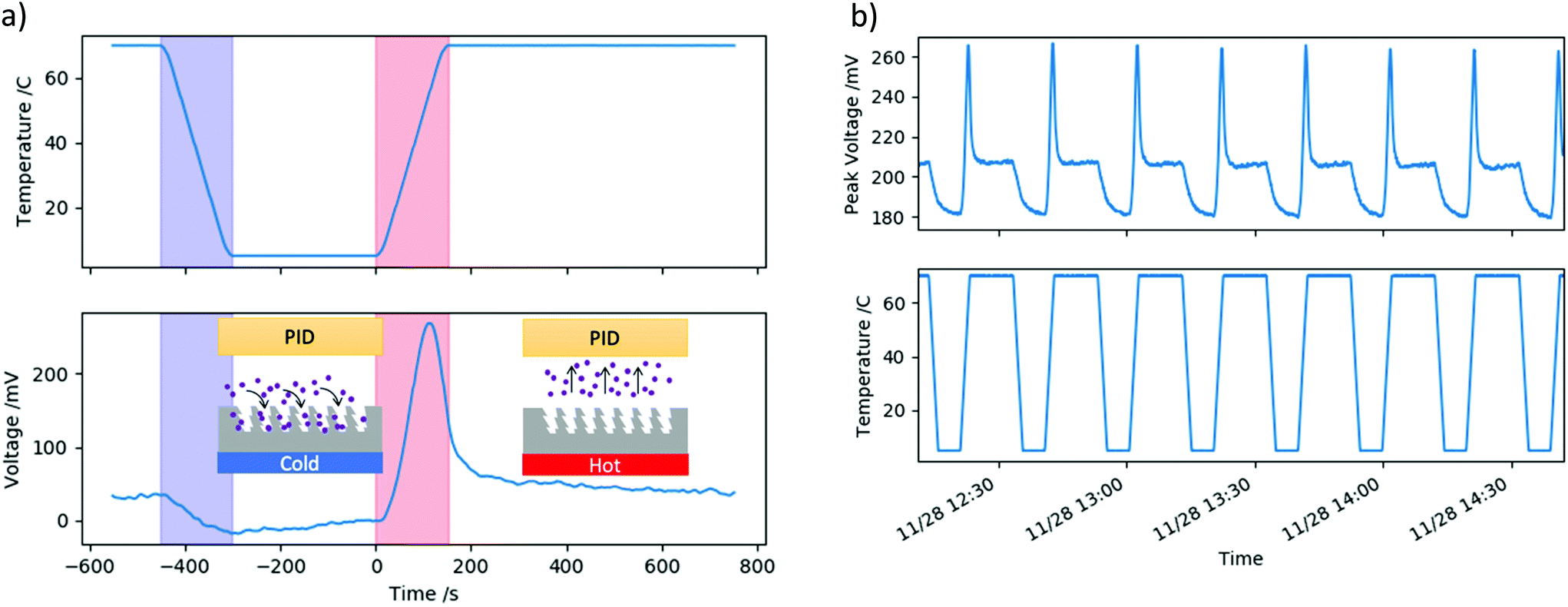 | ||
| Fig. 3 (a) Example of a measurement cycle showing the profile of the applied temperature and the measured PID voltage for 452 ppb o-xylene. The blue band shows the cooling phase and the red band shows the heating phase. (b) Repeated measurement cycles showing the profile of the applied temperature and the measured PID voltage for o-xylene. | ||
As the temperature of the nanoporous silica is decreased from 70 °C to 5 °C, there is a slight decrease in the measured PID voltage seen in Fig. 3a. This is because VOC molecules are being adsorbed into the porous network, and therefore fewer molecules are reaching the PID. During the time the nanoporous material is held at 5 °C, more and more molecules are accumulating in the porous network. Upon heating, at a certain temperature of the nanoporous material, and therefore at a certain time, the VOC desorbs and the PID signal shows a spike in the measured voltage. Then the voltage drops down to the initial baseline as all the VOC has left the porous network.
The repeated cycle response of the VOC adsorption and desorption were investigated under a constant flow of 452 ppb of o-xylene. Fig. 3b shows a series of eight cycles as follows: temperature reduced from 70 °C to 5 °C at a rate of 0.5 °C s−1, held at 5 °C for 300 s, then heated to 70 °C at a rate of 0.5 °C s−1 then held for 600 s. The PID voltage profile shows the same features in each cycle as discussed above; the shape of the profile is very similar for each cycle and the peak height and peak time are also very similar.
Thermal desorption of different VOCs and concentrations
Prior to the thermal desorption cycle described above, the response of the PID to each of the VOCs at the different concentrations was first measured, as a point of comparison. For these measurements, the temperature of the nanoporous silica was held at 70 °C under pure N2 for 600 s, then the VOC was introduced into the N2 flow for 600 s, causing the PID voltage to increase.Fig. 4a shows the time dependent PID voltage for o-xylene at various concentrations. The PID response voltage was calculated by averaging across the top of the plateau for 150 s, and subtracting the baseline voltage, which was also averaged over 150 s immediately before the VOC was introduced. The sampling regions are shown by blue highlights. The standard deviation in both the plateau and baseline voltage measurements were taken and added together to create an estimate of the error in the PID response voltage. The time taken for the initial increase in PID voltage is due to the time it takes for the VOC to pass through the tubing and enter the cell, and for the PID to respond to it.
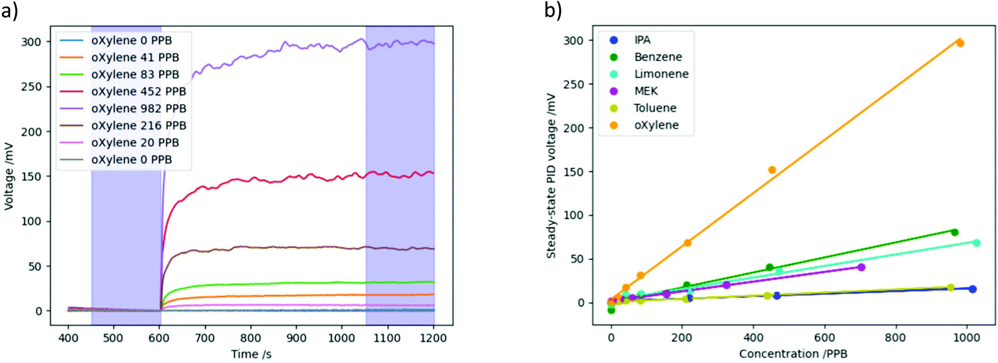 | ||
| Fig. 4 (a) Measured PID voltage vs. time during introduction of different concentrations of o-xylene. Blue bands show sampling regions for calculation of voltage. (b) Curves of PID voltage response as a function of concentration for six different VOCs. | ||
Fig. 4b shows these PID voltages for each VOC, plotted against the VOC concentration, with the error described above shown as error bars (these are very small, so cannot easily be seen for most of the data points). Fig. 4b clearly demonstrates that the response of the PID to each VOC increases linearly with concentration, and that the PID has different sensitivities to different gases.
The thermal desorption cycle was performed for six VOCs at the same range of concentrations as above, and the change in PID voltage over time during the measurement cycle is shown in Fig. 5 together with the molecular structure of the VOCs. The areas highlighted in blue show the times at which cooling was performed, and in red the times at which heating was performed.
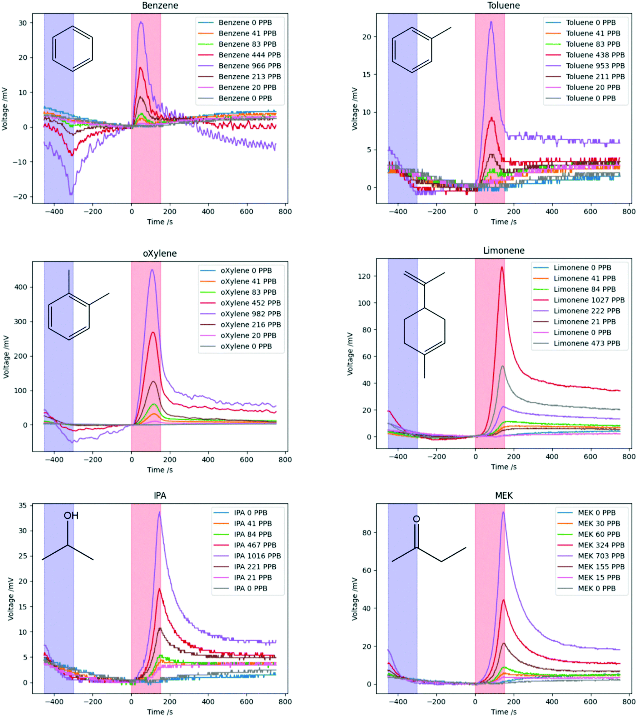 | ||
| Fig. 5 Measured PID voltage over time during thermal desorption cycle for six different VOCS at varying concentrations. On each graph, the blue and red bands show the cooling and heating phases respectively. | ||
In general, for the highest concentrations of the VOCs, the voltage slightly decreases as the nanoporous silica is cooled as discussed above, while for lower concentrations this decrease in voltage does not seem significant. As the temperature is increased, a peak in the measured PID voltage is seen for all but the lowest concentrations. The higher the concentration of the VOC, the higher the peak voltage is.
In addition, it can be seen that the peaks for different VOCs occur at different times; for example, the benzene peaks occur early on while the IPA and MEK peaks occur at the end of the heating phase. The peak heights are significantly different for the different VOCs, and those with higher peaks have less noisy PID responses.
The heights of the desorption peaks seen in Fig. 5 were calculated from the point at which heating begins (0 s), and are plotted as a function of concentration for all VOCs in Fig. 6a, showing an approximately linear relationship for all VOCs tested. Similarly to Fig. 4b, o-xylene produced the largest peak PID response. Limonene and MEK showed the next-largest peak voltage, followed by benzene, IPA and toluene. However, some of this difference in response is due to the inbuilt sensitivity of the PID to different VOCs.
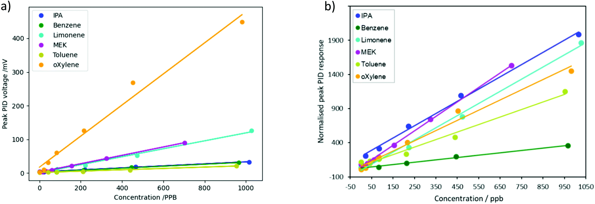 | ||
| Fig. 6 (a) Measured PID voltage peak height as a function of concentration for six different VOCs. (b) Peak PID response to six different VOCs, normalized by the slope of the curves in Fig. 4b. | ||
In order to de-convolute the ordinary PID response from the effect of the porous silica, the peak PID voltages in Fig. 6a were each divided by the constant of proportionality between PID voltage and concentration for each chemical – i.e., the slope of the lines in Fig. 4b. This normalizes the results, to remove the effect of the PID's different sensitivity to the different chemicals. These results, of the normalized peak PID response vs. concentration of each chemical, are shown in Fig. 6b. The normalized height of the peak PID response, i.e. the relative amount of VOC released from the porous silica, was greatest for MEK and IPA, followed by limonene, o-xylene, toluene and then benzene.
This order can be explained by considering the interaction of the VOCs with the surface. MEK and IPA are polar and so have strong interactions with the silica surface, such as dipole–dipole intermolecular forces and hydrogen bonds, and therefore a larger amount of them is adsorbed in the pores. The remaining four compounds are less polar hydrocarbons, and the desorbed amount decreases with decreasing molecular size and boiling point (boiling points are shown in Table 1). The lighter, more volatile compounds such as benzene are not adsorbed as much in the pores, as they have a greater affinity to the gas phase.
| Molar mass (g mol−1) | Boiling point (°C) | Ionisation energy (eV) | VOC conc. (ppb) | Peak time (s) | Peak temp. (°C) | |
|---|---|---|---|---|---|---|
| Benzene | 78.11 | 80.1 | 9.2 | 444 | 50.6 | 24.8 |
| Toluene | 92.14 | 110.6 | 8.8 | 438 | 86.6 | 42.6 |
| o-Xylene | 106.17 | 144.4 | 8.6 | 452 | 112.6 | 55.6 |
| Limonene | 136.24 | 176.0 | 8.3 | 473 | 143.2 | 68.8 |
| MEK | 72.11 | 79.6 | 9.5 | 324 | 149.9 | 69.9 |
| IPA | 60.09 | 82.5 | 10.2 | 467 | 149.4 | 69.8 |
Effect of VOC type on the desorption temperature and time
In order to compare the desorption times and temperatures for the different VOCs, the measured PID voltage over time for each VOC at comparable concentrations were plotted in Fig. 7a. The desorption peaks appear at different times (i.e. at different temperatures of the nanoporous silica) for the different VOCs. In order to determine the position (i.e. time in sec) of the desorption peak of the VOC, the following method was used: starting from the highest point in the data, a quadratic fit is applied to data points 20 s on either side of this point, and the location of the maxima of the quadratic is then determined. This is done to reduce the effect of noise spikes, and although the curves are not actually quadratics, within this small set of data around the peak the fit is good. The temperature at which this peak occurs is found from the time of the fitted peak by interpolating the measured temperature of the nanoporous silica.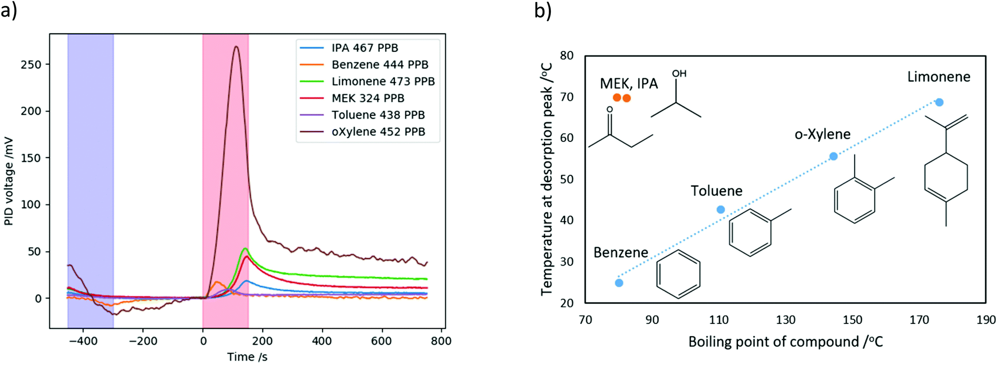 | ||
| Fig. 7 (a) Measured PID voltage over time during thermal desorption cycle for six different VOCs. The blue band shows the cooling phase and the red band shows the heating phase. (b) Temperature of VOC desorption peak as a function of the VOC's boiling point. | ||
The properties of the tested VOCs – molar mass, boiling point and ionization energy,17 and the peak time and peak temperature, are summarized in Table 1. Upon heating, benzene desorbs first at 50.6 s, followed by toluene at 86.6 s, then o-xylene at 112.6 s and limonene at 143.2 s. IPA and MEK desorb last at almost the same time, 149.4 and 149.9 s respectively.
A plot of the temperatures at which the VOCs desorbed from the nanoporous silica as a function of their boiling point of is shown in Fig. 7b. The aromatic and double-bonded hydrocarbon compounds benzene, toluene, o-xylene and limonene have similar affinities to the nanoporous surface and their peak desorption temperature is almost linear with their boiling points; this follows the same trend as the amount of VOC released from the porous silica, shown in Fig. 6b above. The polar compounds MEK and IPA have a significantly stronger affinity to the silica surface, due to the intermolecular forces discussed previously. Therefore, although the boiling points of these compounds are similar to that of benzene, a much higher temperature of the porous surface is required in order to desorb them from the surface. It should be noted that MEK and IPA both desorbed from the surface at almost exactly at the maximum temperature of 70 °C; it is possible that increasing the upper temperature of the range could result in better separation of the desorption peaks of these compounds.
Limonene was desorbed from porous surface at a similar temperature to MEK and IPA, however its boiling point of 176 °C is significantly larger than that of MEK and IPA (both close to 80 °C), demonstrating the effect of the strong VOC interaction with the porous surface. This is also in keeping with the results of Fig. 6b, which demonstrated that this strong interaction also leads to a greater amount of these polar VOCs being adsorbed in the nanoporous silica.
Conclusions
A new approach for improving the selectivity of VOC detection has been presented and demonstrated using a nanoporous preconcentrator and commercially available total VOC detector. In this approach, thermally controlled nanoporous silica adsorbs VOC molecules, which are then slowly thermally desorbed before detection. The height of the desorption peak was found to be approximately linear with the concentration of the VOC. Testing with six different VOCs showed that the time at which they desorb (which is proportional to the temperature of the nanoporous silica) depends on their boiling point and their affinity to the porous surface. In addition, the relative quantity of VOC adsorbed in the porous silica depends on the same factors.This temporally resolved thermal desorption of volatile organics from a nanoporous silica preconcentrator demonstrates the possibility of improving selectivity of VOC detection using a low-cost broadband VOC detector, based on the desorption time and the profile of the desorption peak. This is a different functionality to the common use of preconcentrators discussed in the Introduction, where detector sensitivity is improved by applying a rapid heat increase to desorb all the VOC at once and therefore to provide a high preconcentration factor. In this work, we instead apply a slower temperature increase rate. Although this results in a lower desorption peak, it still marks an improvement in the sensitivity of the detector, as well as potentially offering discrimination between VOCs, and therefore may perform two functions at once.
In addition, it should be noted that, in many potential applications of this technology, humidity may be present in the gas to be analysed. This may cause difficulties, as water molecules are likely to adsorb to the nanoporous silica surface. Therefore, future work involving hydrophobic surface functionalisation of the nanoporous silica will be undertaken to address this. Functionalisation of the surface with different surface chemistries could also help to differentiate between different VOCs.
Additional further work will include testing with mixtures of VOCs and applicability for specific industrial needs, such as the separation of the BTEX compounds. The properties of the nanoporous thermal separator will also be investigated. The surface area, porosity, porous layer thickness, pore size and morphology are all expected to have an effect on the adsorption and desorption of VOCs. It is possible that different operational conditions, such as different minimum and maximum temperatures and temperature change rates, will allow further distinction between the VOCs: these may be optimised in future. It is not yet known how the thermal properties of the nanoporous silica may affect how precisely and uniformly the temperature of the silica can be controlled, which in turn may have an effect on the adsorption and desorption of VOCs.
Conflicts of interest
There are no conflicts to declare.Acknowledgements
The authors would like to thank Tabitha Day for assistance with the computer programming for data analysis and figure plotting. Coco Day is supported by a Vice-Chancellor's Award from the Cambridge Trust. This project was partially funded under the Innovative Research Call in Explosives and Weapons Detection 2016. This is a Cross-Government programme sponsored by a number of Departments and Agencies under the UK Government's CONTEST strategy in partnership with the US Department of Homeland Security, Science and Technology Directorate. The views expressed in this publication are those of the authors and not necessarily those of funding contributors.References
- M. Kampa and E. Castanas, Human Health Effects of Air Pollution, Environ. Pollut., 2008, 151(2), 362–367, DOI:10.1016/j.envpol.2007.06.012.
- L. Thiesan, D. Hannum, D. W. Murray and J. E. Parmeter, Survey of Commercially Available Explosives Detection Technologies and Equipment 2004, Document No.: 208861. Sandia National Laboratories, National Institute of Justice February 2005.
- S. Sethi, R. Nanda and T. Chakraborty, Clinical Application of Volatile Organic Compound Analysis for Detecting Infectious Diseases, Clin. Microbiol. Rev., 2013, 26(3), 462–475, DOI:10.1128/CMR.00020-13.
- L. Spinelle, M. Gerboles, G. Kok, S. Persijn and T. Sauerwald, Review of Portable and Low-Cost Sensors for the Ambient Air Monitoring of Benzene and Other Volatile Organic Compounds, Sensors, 2017, 17(7), 1520, DOI:10.3390/s17071520.
- H. Lahlou, X. Vilanova and X. Correig, Gas Phase Micro-Preconcentrators for Benzene Monitoring: A Review, Sens. Actuators, B, 2013, 176, 198–210, DOI:10.1016/j.snb.2012.10.004.
- M. Leidinger, T. Sauerwald, C. Alépée and A. Schütze, Miniaturized Integrated Gas Sensor Systems Combining Metal Oxide Gas Sensors and Pre-Concentrators, Procedia Eng., 2016, 168, 293–296, DOI:10.1016/j.proeng.2016.11.199.
- M. Leidinger, M. Rieger, T. Sauerwald, C. Alépée and A. Schütze, Integrated Pre-Concentrator Gas Sensor Microsystem for Ppb Level Benzene Detection, Sens. Actuators, B, 2016, 236, 988–996, DOI:10.1016/j.snb.2016.04.064.
- Z.-Y. Gu, G. Wang and X.-P. Yan, MOF-5 Metal−Organic Framework as Sorbent for In-Field Sampling and Preconcentration in Combination with Thermal Desorption GC/MS for Determination of Atmospheric Formaldehyde, Anal. Chem., 2010, 82(4), 1365–1370, DOI:10.1021/ac902450f.
- H. Lahlou, J.-B. Sanchez, X. Vilanova, F. Berger, X. Correig, V. Fierro and A. Celzard, Towards a GC-Based Microsystem for Benzene and 1,3 Butadiene Detection: Pre-Concentrator Characterization, Sens. Actuators, B, 2011, 156(2), 680–688, DOI:10.1016/j.snb.2011.02.018.
- C. Pijolat, M. Camara, J. Courbat, J.-P. Viricelle, D. Briand and N. F. de Rooij, Application of Carbon Nano-Powders for a Gas Micro-Preconcentrator, Sens. Actuators, B, 2007, 127(1), 179–185, DOI:10.1016/j.snb.2007.07.029.
- E. H. M. Camara, P. Breuil, D. Briand, N. F. de Rooij and C. Pijolat, A Micro Gas Preconcentrator with Improved Performance for Pollution Monitoring and Explosives Detection, Anal. Chim. Acta, 2011, 688(2), 175–182, DOI:10.1016/j.aca.2010.12.039.
- M. Li, S. Biswas, M. H. Nantz, R. M. Higashi and X.-A. Fu, A Microfabricated Preconcentration Device for Breath Analysis, Sens. Actuators, B, 2013, 180, 130–136, DOI:10.1016/j.snb.2012.07.034.
- A. Rydosz, W. Maziarz, T. Pisarkiewicz, K. Domański and P. Grabiec, A Gas Micropreconcentrator for Low Level Acetone Measurements, Microelectron. Reliab., 2012, 52(11), 2640–2646, DOI:10.1016/j.microrel.2012.05.012.
- B. C. Giordano, D. C. Ratchford, K. J. Johnson and P. E. Pehrsson, Silicon Nanowire Arrays for the Preconcentration and Separation of Trace Explosives Vapors, J. Chromatogr., A, 2019, 1597, 54–62, DOI:10.1016/j.chroma.2019.03.045.
- M. Leidinger, T. Sauerwald, W. Reimringer, G. Ventura and A. Schütze, Selective Detection of Hazardous VOCs for Indoor Air Quality Applications Using a Virtual Gas Sensor Array, JSSS, 2014, 3, 253–263, DOI:10.5194/jsss-3-253-2014.
- P. Granitzer and K. Rumpf, Porous Silicon—A Versatile Host Material, Materials, 2010, 3(2), 943–998, DOI:10.3390/ma3020943.
- P. J. Linstrom and W. G. Mallard, NIST Chemistry WebBook, NIST Standard Reference Database Number 69, National Institute of Standards and Technology, Gaithersburg MD, 20899, 2018, DOI:10.18434/T4D303.
Footnotes |
| † Electronic supplementary information (ESI) available: Schematic of gas flow system and pore size distribution. See DOI: 10.1039/d0an01822h |
| ‡ These authors contributed equally to this work. |
| This journal is © The Royal Society of Chemistry 2021 |