
 Open Access Article
 This Open Access Article is licensed under a Creative Commons Attribution-Non Commercial 3.0 Unported Licence
Detection techniques of biological and chemical Hall sensors
Hua Fana,
Jiangming Wanga,
Quanyuan Fengb,
Qiang Huc,
Siming Zuod,
Vahid Nabaeid and
Hadi Heidari d
d
aState Key Laboratory of Electronic Thin Films and Integrated Devices, University of Electronic Science and Technology of China, Chengdu, China. E-mail: fanhua7531@163.com
bSouthwest Jiaotong University, Chengdu, China. E-mail: fengquanyuan@163.com
cJihua Laboratory, Foshan, China. E-mail: huqiang@jihualab.com
dJames Watt School of Engineering, University of Glasgow, Glasgow, G12 8QQ, UK. E-mail: hadi.heidari@glasgow.ac.uk
First published on 11th February 2021
Abstract
Integrated magnetic Hall effect sensors have been widely used in people's daily life over the past decades, and still are gaining enormous attention from researchers to establish novel applications, especially in biochemistry and biomedical healthcare. This paper reviews, classifies, compares and concludes state-of-the-art integrated Hall magnetic sensors in terms of cost, power, area, performance and application. Current applications of the Hall sensors such as detecting magnetic nanoparticles (MNPs) labeled on biomolecule, monitoring blood pulse wave velocity, characterizing soft biological materials, controlling syringe injection rate and eye surgery by training systems, and assisting magnetic resonance imaging (MRI) will be discussed comprehensively and future applications and trends will be highlighted. This review paper will introduce Hall sensor's advantages such as simple design and technology of manufacturing, low cost, low power consumption, possibility of the miniaturizing, noninvasive and room temperature measurement, with respect to the other magnetic sensing systems and methods.
1 Introduction
Sensor technology is one of the three pillar industries of modern information technology. Hall sensors are widely used in industrial control, consumer electronics, biodefense, medical diagnostics, food safety, environmental monitoring and other fields due to their simple structure and low cost. The principle of realizing magnetic sensors includes Hall effect,1,2 and magnetoresistance effect.3 The Hall effect can be described as when the current in a conductor or semiconductor passes through an external magnetic field, the movement of carriers is affected by the Lorentz force and shifts. Since the accumulation of electrons generates an additional electric field in the direction perpendicular to the magnetic field and the current plane, a potential difference is generated across the semiconductor or conductor. This potential difference is called the Hall voltage. The development of complementary metal-oxide semiconductor (CMOS) technology has made Hall sensors more miniaturized and application scenarios more diverse.4 The Hall voltage VHall is calculated:
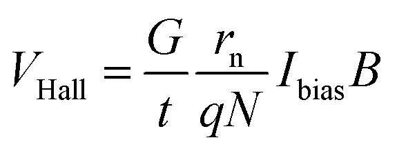 | (1) |
The magnetoresistance effect was discovered by Thomson in 1856. It refers to the phenomenon that when a magnetic field is applied to an energized object under certain circumstances where the applied magnetic field is inconsistent with the internal magnetization direction of the object, the magnetic field will change the direction of the current, thereby changing the resistance value of the material. Magnetoresistive sensors show superior performance in sensitivity and signal-to-noise ratio, but they are expensive with CMOS manufacturing processes.
Today, magnetic sensors are the key elements in several fundamental studies as well as industrial applications. The demand of biomedicine expands the application scenarios of Hall sensors, benefiting from their low price. Various magnetic sensing devices such as superconducting quantum interference devices (SQUIDs),5–8 magnetic resonance imaging (MRI),9–11 nuclear magnetic resonance (NMR)12,13 have been utilized in these areas. These devices exhibit high sensitivity, however, their large physical size and expensive price limit their popularity.14,15 If required a momentary and enormous screening tests for diseases like Ebola and SARS, traditional bulky devices are not suitable.16 Considering advantages of magnetic sensing technologies, the miniaturized systems bring down the size and cost because of benefits from integrated thin-film magnetic sensors like Hall sensors17–22 giant magnetoresistance (GMR)23,24,24–29 and tunneling magnetoresistive (TMR)30–32 and fluxgate sensors,33,34 etc. Although the GMR and fluxgate sensors can be integrated with sensor readout circuitry to significantly reduce system size35–37 and they are more sensitive than Hall sensors to detect the weak magnetic field, the used materials for fabrication are relatively not common in the foundry, which causes high cost for the GMR, TMR and fluxgate sensors.14,15,38–40 In addition, some biomedical applications do not need such a high sensitivity sensor.16 At present, the Hall sensors are the most widely used magnetic sensor in the market, which exhibit small physical size, low-cost and is compatible with standard CMOS technology.41–47
Fig. 1(a) demonstrates the basic concept and application scenarios of Hall sensor, while Fig. 1(b) shows the number of publications in magnetic sensors and the Hall sensors used in biomedical applications during the last 20 years (from 2000 to 2020). It is obviously noted that the researches of Hall sensors are significantly increased by years, similarly with trend of the total magnetic sensors.
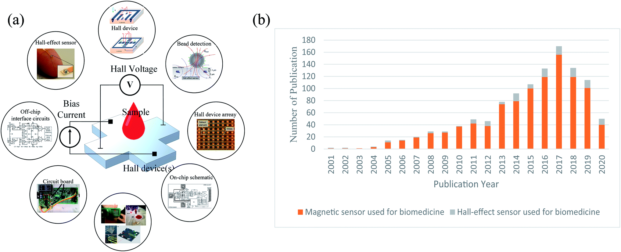 | ||
| Fig. 1 (a) The concept of Hall-effect sensor used for biomedical applications; (b) developing tendency for magnetic sensor and Hall-effect sensor used for biomedicine. | ||
We collected, classified, compared and concluded the integrated Hall sensors used in biomedical applications in recent years (from 2014 to 2020), including detection of DNA, protein and blood using MNPs as the bio-labels, monitor of blood pulse wave velocity, characterization of soft biological materials, control of syringe injection rate and eye surgery by training systems, and MRI assistance. The overview of Hall applications is demonstrated in Fig. 2. The Hall sensor is an innovative tool for detecting MNPs as an applicable and challenging task.48–54 This paper reviews the Hall sensor applications and introduces them specifically. Since the available commercial Hall sensors are not commonly suitable from sensitivity, size, shape and compatibility points of view for the MNP detection,16,49,55–59 we focus on the homemade Hall sensors developed by different research groups.
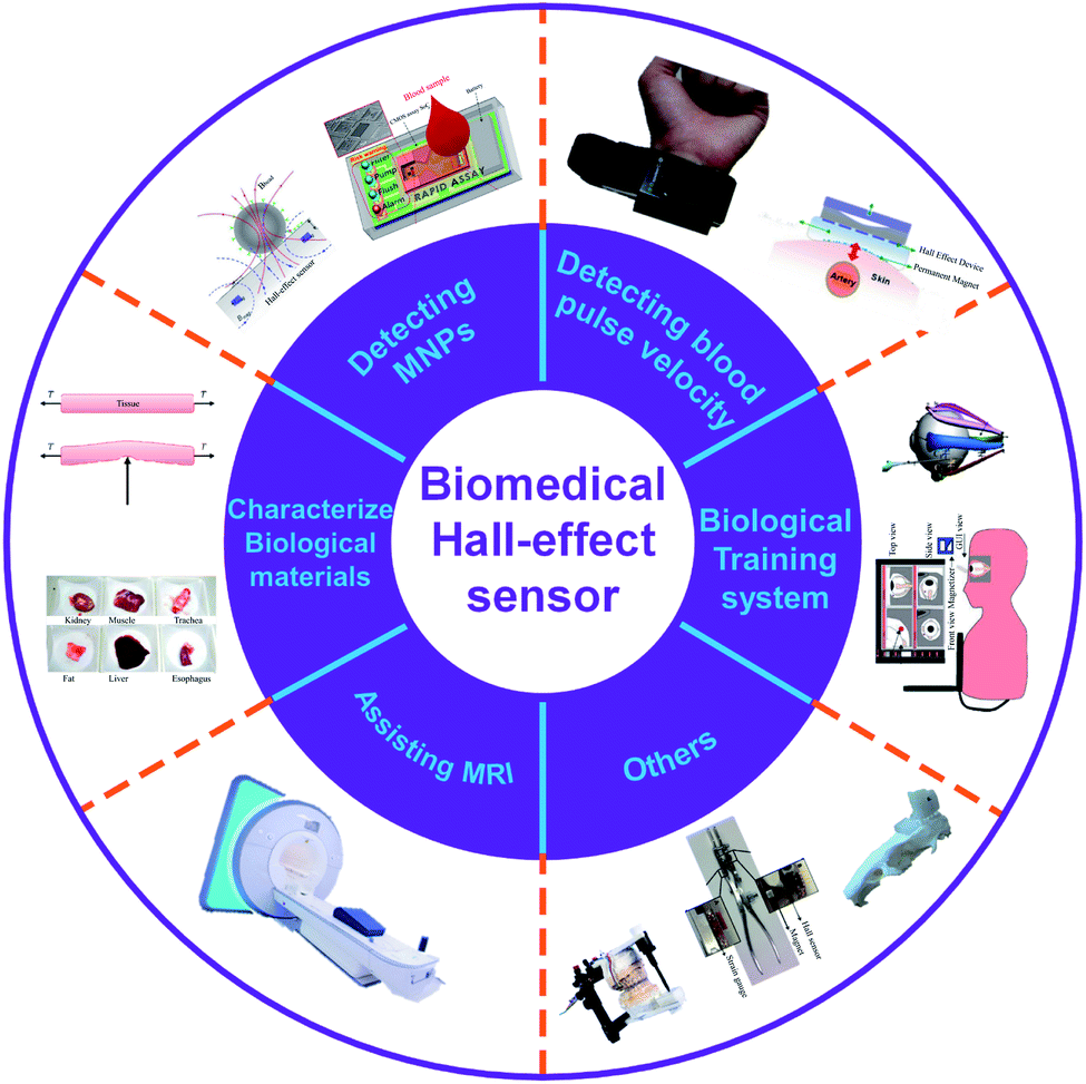 | ||
| Fig. 2 Classified applications of Hall-effect sensor used for biomedicine. | ||
2 Hall sensor for bio-chemical detection
The MNP based bio-labels have attracted many researchers' attention over the past decade.40,56,60–63 The Hall sensor size can be several micrometres, which lays the foundation for portable biochemical detection. Magnetic substances are suitable as labels because their signals are relatively stable in biological systems and buffers. When a substance needs to be detected, magnetic particles are commonly mixed into it, and then a magnetic sensor is used to measure the magnetic field of the substance to be measured. It is noted that there is no considerable magnetic field from the human body compared with fluorescent based methods.14,15,61,64 The typical detection structure of MNPs for immunoassay includes four steps, as shown in Fig. 3(a): (1) bound detection antibody with MNPs and fix capture antibody on the sensing surface;65–67 (2) add antigen to sensing area where the antigen is captured by the capture antibody; (3) add the detection antibody bounding with MNPs to sensing area and then captured by the antigen; (4) wash uncaptured detection antibody bound with MNPs by using magnetic field inducing in an inner coil or an external magnet.68,69 The number of MNPs bounded on the sensing area is related to the antigen's number, which will lead to different output signals from Hall sensors.70–73 The typical detecting system adopt technique so-called ac–dc.56,62,64,74,75 As shown in Fig. 3(b), DC magnetic field is utilized to magnetize the MNPs while AC magnetic field is employed to induce the detection signal and remove the background noise. The detection effect of MNPs mainly depends on the performance of the Hall sensor and the magnetization system. The sensor characteristics include Hall-device array,16,57,58 processing technology,16,55,57,58 die size16,57,58 and sensor sensitivity.16,57,58 The Hall-device array is a unique approach to enhance the detection efficiency compared with a single Hall element.57 The processing technology and die size are related to prime cost and volume of the sensor. Additionally, the sensitivity is a major feature of detection systems and the others include different detection methods, target antigens and immunoassay platforms. The magnetization systems are used to magnetize and adsorb the MNPs.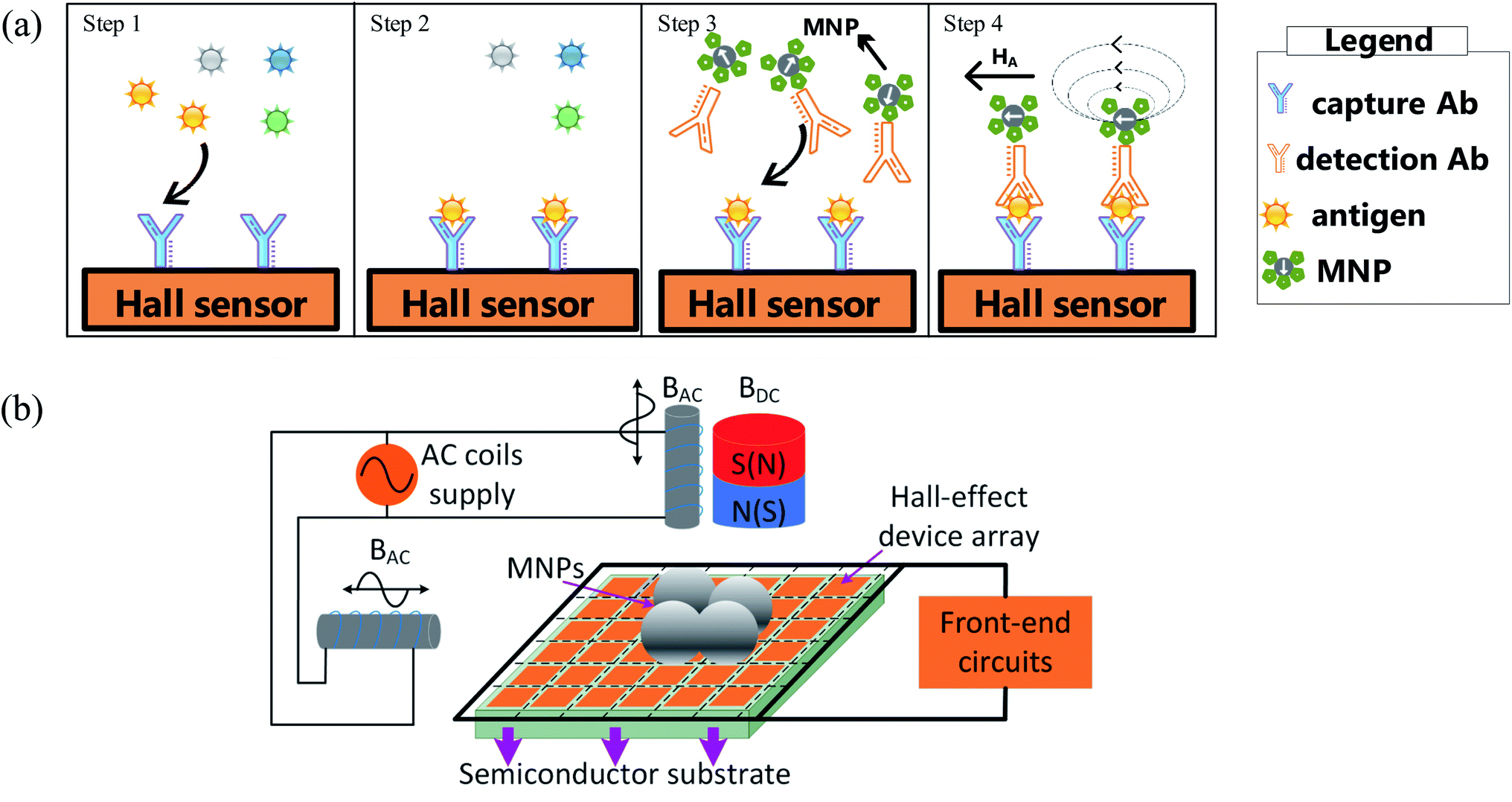 | ||
| Fig. 3 (a) Step 1. Introduce a magnetically labeled antibody, bind the detection antibody to MNP and fix the capture antibody on the sensing surface; step 2. Add antigen to the sensing area where the captured antibody captures the antigen; step 3. The detection antibody that binds to MNPs is added to the sensing area and then captured by the antigen; step 4. Wash the uncaptured detection antibody bound to MNP by using the magnetic field in the internal coil or external magnet. (b) Typical system used to detect MNP: using AC–DC Hall magnetic method, this method can clearly and reliably separate the real and parasitic magnetic signals of very small amplitude. | ||
Recently, Kuo et al. implemented the Hall sensor to detect the concentration of Tumor necrosis factor-α (TNF-α, related to anti-tumor) and N-terminal pro-brain natriuretic peptide (NT-proBNP, related to heart failure) by using a label based on 1.5 μm MNPs.16 By referring to Fig. 4(a and b), in vitro tumor necrosis factor-α (TNF-α) and NT-proBNP tests were performed. The concentrations of TNF-α and NT-proBNP solutions range from 0.8 pg mL−1 to 800 ng mL−1. These can be detected by the Hall sensor from the change of Hall voltages. The warning threshold can be preset so that when the concentration exceeds the preset value, the user will be warned for further inspection. An 8 × 8 Hall device array is adopted and fabricated using the 0.35 μm CMOS technology with die size of 8.89 mm2. It has achieved 0.039 V/V/T sensitivity. The chip is based on a system on chip structure in which a microcontroller unit can control the detection process automatically. Generally, the detection process can be divided into four steps, as shown in Fig. 4(c): (1) filtering target (TNF-α or NT-proBNP) into a chip reservoir to divide targets and blood cells through an anodic aluminium oxide; (2) pumping bubbles induced by electrolytic water to move the target into a sensing area; (3) flushing unbound MNPs in the sensor area by inducing a magnetic field from a chip inner coil; (4) starting a detection action. An alarm LED will illuminate when the concentration of bound MNPs exceeds the static setpoint. There is a log relationship between the number of MNPs and the output voltage generated by an analog front-end of a single Hall device.
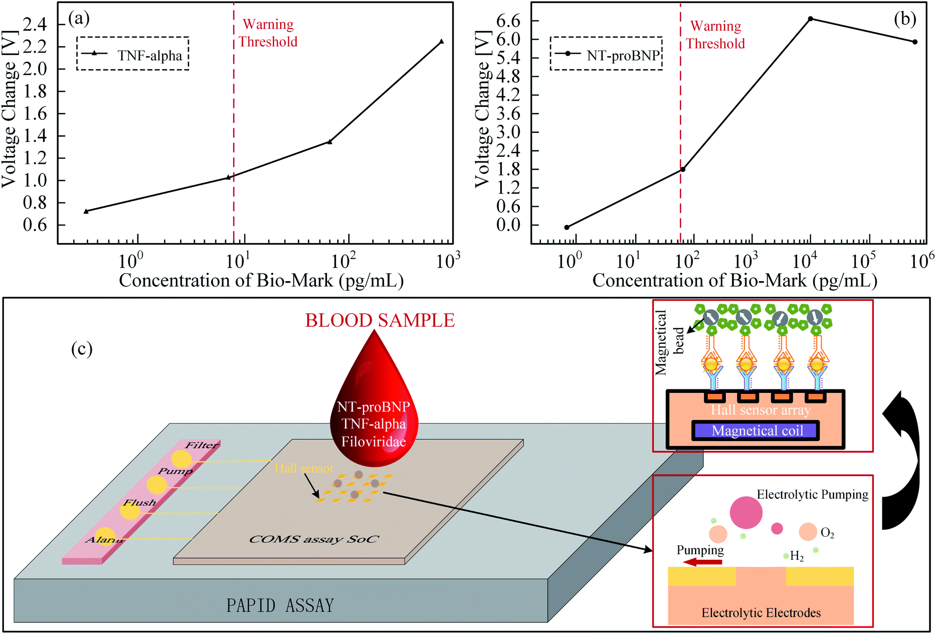 | ||
| Fig. 4 (a) The relationship between the total output voltage changes of 64 Hall sensors and different TNF-alpha concentrations, the cordon concentration is set at 8 pg mL−1, and the corresponding Hall voltage is 1 V; (b) relative to different NT-proBNP concentrations, the total output voltage of 64 Hall sensors changes, the cordon concentration is set to 70 pg mL−1, and the corresponding Hall voltage is 1.8 V; (c) a system on chip for rapid blood detection. A microcontroller unit with the 4 steps detection process of filter, pump, flush and detection automatically. If the bound MNPs exceed the static set value, the Alarm LED will light up.16 | ||
In addition, Gambini has implemented the Hall sensor to detect the concentration of Human Serum Albumin (HSA).57 The normalized chip output is changed with the concentration of HAS, as shown in Fig. 5(a). A 64 × 160 Hall-device arrays is adopted and fabricated using the 0.18 μm CMOS technology with a die size of 17.85 mm2. Its sensitivity could reach 0.029 V/V/T. However, conventional methods have a low 1% signal-to-baseline ratio, which means 1% fluctuation of the baseline can lead to a considerable signal error. To resolve this problem, they considered the dynamic property of MNPs to measure the magnetic field of magnetized MNPs in their relaxation time, as shown in Fig. 5(b and c). In theory, the baseline of the magnetic field should be zero in the relaxation measurement. Therefore, the signal-to-baseline ratio is infinite and their sensor achieves a ratio larger than 1. In particular, compared with their previous design, adopting a single channel with the readout time 64 s in 2012,76 the group implements a parallel readout channel where the readout time is only 8 s. Finally, since the MNPs have small physical size and magnetic field signal, it is vulnerable to environmental noise, earth's magnetic field and unsteady baseline etc. Therefore, this group also introduced a specific circuit design scheme to obtain the accuracy signal of the MNPs. M450 (4.5 μm), M280 (2.8 μm), M1 (1 μm) are utilized as a verification of the sensor function, as shown in Fig. 5(d). There is approximately a linear relationship between the number of beads and the sensor output.
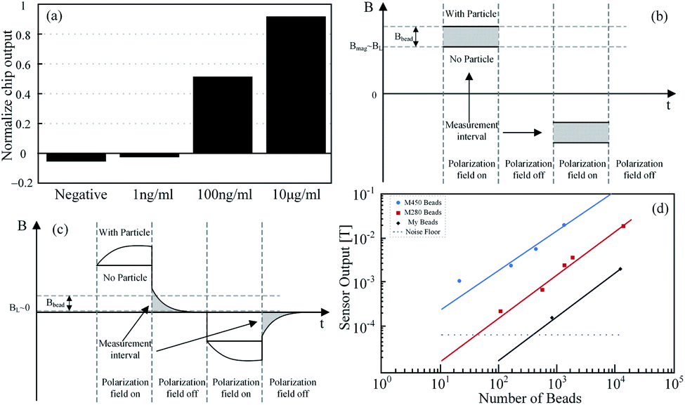 | ||
| Fig. 5 (a) That the normalized chip output changes with the concentration of HAS; (b) M450, M280 and My1 are used for experiments, and sensor outputs is proportional to the number of MNPs, respectively;57 (c) conventional measurement method has small signal-to-baseline ratio; (d) considering the dynamic property of MNPs, the magnetic field generated by MNPs do not vanished immediately upon external magnetic field vanished. In theory, signal-to-baseline ratio is infinite in the moment.57 | ||
Bhalla et al. have used the Hall sensor to detect the concentration of Adiponectin (related to fat) using 10 nm MNPs as a label.55 The sensor is fabricated by using the 0.35 μm BioMEMS technology and has the sensitivity of 26 V/A/T. The phase shift of the sensor output signals between inductor 1 (without MNPs) and inductor 2 (with MNPs) indicated a linear relationship with MNPs concentration on the microfluid platform, as shown in Fig. 6(a and b). The microfluidic platform has eight chambers in total, five of which are used for loading reagents and the others for washing reagents, reaction and waste chambers. A system structure of the microfluidic platform experiment is demonstrated in Fig. 6(c). The immunoassays process takes 2 hours and 15 minutes, including incubation bounding MNPs with the antibody, washing and detection etc.
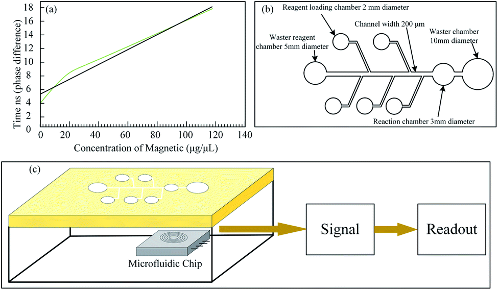 | ||
| Fig. 6 (a) Phase shift versus concentration of MNPs; (b) microfluidic platform totally has eight chambers, five of which are used for reagent loading and the rest three of which is used for washing reagent, reaction chamber and waste chamber; (c) the system structure of microfluidic platform experiment.55 | ||
Kim et al. have built a microfluidic platform where a planar Hall magnetoresistive (PHR) sensor is implemented to investigate the property of MNPs, as show in Fig. 7(a).77 Schematic drawing of on chip magnetometer, in which the channels (F1–F4) represented in purple color are flow channels for the generation of ferrofluid droplets, and the channels (C1–C4) represented in red color are control channels (valves) for the operation of ferrofluid droplet oscillation. A linear relationship is obtained between the concentration of MNPs and magnetization measured indirectly by the PHR sensor in ferrofluid, as shown in Fig. 7(b). The sensor is fabricated on a silicon wafer using a NiFe/Cu/IrMn trilayer structure with an absolute sensitivity of 0.085 V/V/T. A Maxwell software has been carried out to simulate the magnetic field in a droplet sensing area and optimize the length of the droplet in the microfluidic platform, as shown in Fig. 7(c). It is noted that the critical length to have apparent signals is 70 μm. The output signal of the PHR sensor is in corresponds to different positions of droplets and also different magnetic fields.78,79
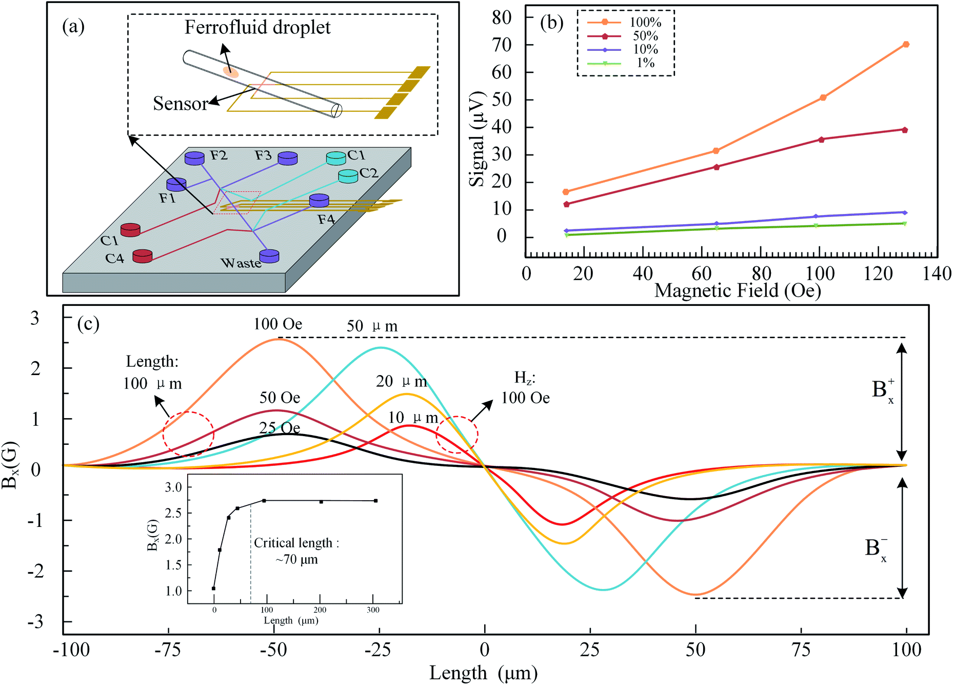 | ||
| Fig. 7 (a) Microfluidic platform with PHR sensor in the middle; (b) magnetization measured indirectly by PHR sensor is proportional to the concentration in the ferro-fluid droplets containing MNPs; (c) a simulation using Maxwell software, 70 μm is the critical length of droplet, above which the droplet signals are apparent.77 | ||
Østerberg have applied the Hall sensor to detect the existence of DNA using 40 nm MNPs as a label, shown in Fig. 8(a and b).80 A new structure Hall device, planar Hall bridge proposed by Henriksen and Persson et al. was adopted.81,82 The sensor is fabricated on a standard silicon wafer with a deposited structure of Ta/Ni80Fe20/Mn80Ir20/Ta. It is worth mentioning that the sensor sensitivity is 6 times larger than the cross-shaped planar Hall sensor. The basic detection principle is that the MNPs with different sizes have different Brownian relaxation frequencies where the AC susceptibility reaches maximum. The reverse proportional relationship between MNP volume, Vh and Brownian relaxation frequency, fB is expressed as eqn (2)
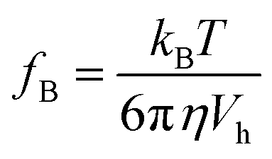 | (2) |
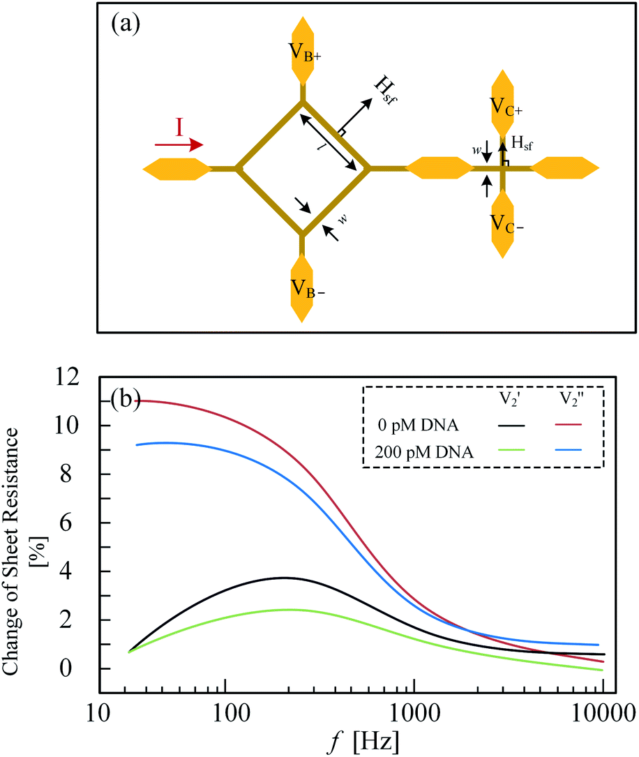 | ||
| Fig. 8 (a) Left sensor is planar Hall-effect bridge device sensor and right sensor is a cross-shaped planar Hall-effect device; (b) planar Hall-effect bridge device detects 0 pM and 200 pM DNA, respectively.80 | ||
In more recent works, Loan et al. have investigated the processing technology for ultraclean graphene film without the photoresist polymethyl methacrylate (PMMA) residue.83 A new method for detecting DNA is employed without using MNPs. The Hall devices were designed based on the ultraclean graphene and the PMMA residue-based graphene respectively. The sensor sensitivity based on the ultraclean graphene is about 5 times larger than the one based on the PMMA residue. A DNA experiment was carried out on the ultraclean graphene-based sensor surface. Finally, the carrier concentration, carrier mobility and sheet resistance of Hall device are related to the concentration of DNAs. Their relationships are shown in Fig. 9(a–d).
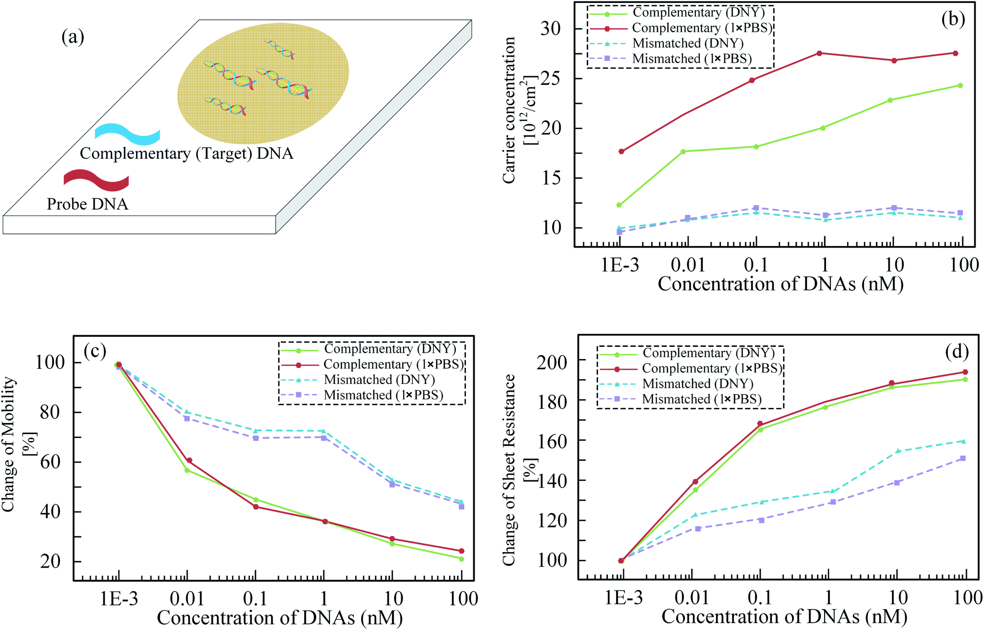 | ||
| Fig. 9 (a) DNA sample on Hall-effect device; (b) carrier concentration, (c) carrier mobility, and (d) sheet resistance of Hall effect device versus to DNAs concentrations, respectively.83 | ||
Except for the detections of DNA, protein and blood outside the human body, the Hall sensor and MNPs are also a versatile device for disease detections inside of the human body. For instance, Ookubo et al. and Kuwahata et al. have implemented a Hall sensor (NHE520) to detect magnetic fluid containing MNPs for sentinel lymph node biopsy.84,85
3 Performance development
The Hall effect was first discovered in 1897, but the first application did not appear until after 1950, and the device cost was very high. Since 1965, Hall sensors have become the first choice for solid-state magneto-sensitive devices due to their advantages of being fully integrated into silicon chips. Most of the magnetic sensors produced to use the Hall effect. Hall sensitivity is greatly influenced by semiconductor materials, and the characteristics of various materials are shown in Table 1. In order to achieve the highest possible sensitivity, the electron mobility of the material needs to be as high as possible. InSb and InAs telluride have extremely high mobility, but the bandgap is extremely narrow. For narrow bandgap semiconductors to obtain excellent temperature performance, the semiconductor must be heavily doped. Heavy doping is bound to offset its original advantage of high mobility. The Hall sensitivity of a silicon sensor is usually 1 mV mT−1 at a current of 1 mA. The sensitivity of the Hall sensor made of InSb material is typically 5 mV mT−1, and the typical value of InAs is 2 mV mT−1.86| Material | Band gap (eV) 300 K | Electron mobility (cm2 V−1 s−1) | Dielectric constant |
|---|---|---|---|
| Si | 1.1242 | 1450 | 11.9 |
| Ge | 0.6643 | 3800 | 16.2 |
| InSb | 0.18 | 5.25 × 10⁵ | 17.3 |
| InAs | 0.354 | 2.50 × 10⁴ | 15.15 |
| GaAs | 1.424 | 8000 | 12.9 |
As the low-cost characteristic and CMOS compatibility, Hall-effect sensors were commonly used in the automation field. Researchers have considered magnetic sensor for novel applications in the detection of MNPs. The diameter of MNPs is very small, usually, only a micrometer or nanometer leading to few molecule electric current and weak magnetic. III–V semiconductor Hall devices are frequently utilized in the early exploration due to their superior characteristic for the weak magnetic field.14,56,61–63,65,66,78,87,88 For example, InSb Hall device can detect the weak magnetic field as low as picoTesla,89,90 and GaAs sensor can detect nanotesla easily. InAs is considered mostly in the early period because of its ultra-high mobility up to 2.5 × 104 cm2 V−1 s−1 (silicon is 1450 cm2 V−1 s−1) which lead to high sensitivity of Hall-effect device. InSb and InGaAs are also common materials used in the early exploration. However, comparing to silicon Hall-device, all of them hardly have the processing technology to integrate Hall-devices with complex circuits. Mature CMOS bio-Hall integrated sensors have emerged in recent years. The performance and the characteristics of Hall sensor are presented in Table 2.
| Reference | Sensitivity/noise | Power dissipation | Size & processing technology |
|---|---|---|---|
| Besse et al.49 (Hall sensor) | 175 V/A/T | 2.55 mW | 2.4 μm × 2.4 μm, 0.8 CMOS |
| 0.02 V/V/T | |||
| 0.2 μT/rt (Hz) | |||
| Aytur et al.91 (Hall sensor) | — | 500 mW | 2.2 mm2 chip, 0.25 RF CMOS |
| Ishikawa et al.58 (Hall sensor) | — | 500 mW | 2.3 mm2 chip, 0.25 RF CMOS |
| Liu et al.76 (Hall sensor) | 0.029 V/V/T | 10.4 mW chip | 0.18 CMOS |
| 120 nT/rt (Hz) | 138 mW system | ||
| Gambini et al.57 (Hall sensor) | 0.029 V/V/T | 300 mW system | 0.18 CMOS |
| 270 nT/rt (Hz) | |||
| Bhalla et al.55 (Hall device) | — | — | 0.35 BioMEMS |
| Kuo et al.16 (Hall sensor) | 0.039 V/V/T | 2.65 mW chip | 0.35 CMOS |
| 214 nT/rt (Hz) | |||
| Kim et al.77 (Hall device) | 85 V/A/T | NiFe/Cu/IrMn | |
| Ishikawa58 (Hall sensor) | — | — | 2.2 mm2 chip, 0.35 CMOS |
Besse et al. implemented a high-sensitivity silicon CMOS Hall sensor to detect magnetic microbeads with a diameter of 2.8 μm. Two detection methods using the superparamagnetic properties of magnetic beads were tested experimentally, and their performances were compared. Their work is based on the use of silicon Hall sensors and dense arrays of CMOS electronics, opening the way for low-cost microsystems for biochemical applications. Liu et al. designed a CMOS Hall sensor chip specifically for characterizing and detecting magnetic nanoparticles. Its time resolution is three orders of magnitude higher than existing solutions based on superconducting quantum interference devices and fluxgate sensors. Bhalla et al. used TSMC's 0.35 μm process to design and manufacture Hall sensors that can be used to detect specific proteins contained in 10 nm magnetic beads. It can achieve a rapid detection in 2 hours and 15 minutes while ensuring accuracy, which provides convenience for handling emergencies. Kuo et al. utilized MCU(Micro control unit) to complete a fully automated immunoassay laboratory, and the main sensor used is a Hall magnetic sensor made of 0.35 μm CMOS process. The Hall sensor designed by Gambini et al. under the 0.18 μm CMOS process contains 8 × 8 Hall devices. Compared with a single Hall device, this method's measurement sensitivity of to the magnetic beads is improved by more than 50 times. Another advantage is that the combination of multiple Hall devices can minimize the misalignment caused by process factors.
With the development of microelectronic technology, the sensitivity, size, and power consumption of Hall sensors are constantly optimized. The preliminary results in the field of biochemistry have attracted some people's attention to Hall magnetic sensors. There will be more scientific researchers to explore the potential of Hall magnetic sensors. Low price, high accuracy, multi-function, and easy to carry testing equipment are the mainstream research directions.
4 Biochemistry applications and future directions
4.1 Application I: blood pulse wave velocity detection
The pulse signal of the artery contains much pathophysiological information about the cardiovascular system. The speed and strength of these pulse waves propagating through arteries are powerful indicators for judging cardiovascular diseases. At present, the measurement of local PWV (Pulse Wave Velocity) is achieved by a variety of signal acquisition techniques, such as Doppler ultrasound, magnetic resonance imaging, etc. However, these systems are costly and require professional operation to obtain accurate and reliable measurements. Recently, Nabeel et al. have developed a PWV rapid detection system composed of Hall sensors and permanent magnets with a simple, reliable and cheap structure. The non-invasive measurement of ΔT was achieved by placing the same pulse detection sensor on the two arterial parts. As shown in Fig. 10(a), there is a significant pulse propagation delay between the pulse waveforms recorded at two different measurement points simultaneously. PWV is proportional to the average pulse propagation speed. The MPG (Magnetic Plethysmograph) sensor for arterial pulse detection is utilized for superficial artery pulse detection. The MPG sensor structure is shown in Fig. 10(b), using a disk-shaped permanent magnet to generate the necessary environmental magnetic field. A linear through-hole SIP type Hall-effect integrated circuit is placed near the permanent magnet as the required magnetic sensor to capture magnetic field fluctuations. In addition, Nabeel et al. have implemented a magnet and a Hall sensor (SS49E T3, SEC Electronics Inc.) to build prototype equipment for the PWV detection.92 Subsequently, they optimized the design with a dual Hall sensor (SS49E T3, SEC Electronics Inc.) structure in 2014.93 The earlier PWV detections devices of Nam et al. (A1395, Allegro),94 Kim et al. and Lee et al. were designed similarly called clip-type devices but with different structures,95,96 as shown in Fig. 10(c). | ||
| Fig. 10 (a) System architecture of Hall-effect sensor and magnet for detecting blood PWV;93 (b) the probe structure by using Hall-effect sensor parallels to magnet;93 (c) the probe structure by using Hall-effect sensor above the magnet.96 | ||
4.2 Application II: training system for syringe and eye surgery
The medical training system is an essential means to train doctors to master surgical skills. Using a syringe to inject fluids into the body is a common clinical practice. The injection speed can have various pathological effects on the body, such as the perceived pain, or the exercise capacity achieved under anesthesia. Mukherjee et al. have built a new generation syringe training system based on a commercial Hall sensor (SS49E, Honeywell) as a displacement sensor.97 To help students observe and practice the injection rate before injecting the human body. The design of the injection is shown in Fig. 11(a). The main body of the syringe includes a standard ready-made syringe. The ring-shaped permanent magnet is attached to the syringe body in the magnet holder. Two Hall sensors are located on the top and bottom of the needle tube. As shown in Fig. 11(b), the magnetic field generated by the ring magnet is perpendicular to the two Hall sensors. When the piston moves relative to the syringe body, one Hall-effect sensor approaches the magnet and the other moves away from the magnet, creating a differential operating mode. By comparing the difference of the magnetic fields received by the two Hall sensors, the position of the permanent magnet is judged, and the injection rate is obtained. In 2013, researchers have implemented at a modified syringe where capacitances are fixed a certain position on a needle to build an ophthalmic anesthesia training system,98 as shown in Fig. 11(c). Regional anesthesia for eye surgery is to insert the syringe needle into the eye socket in the proper position and direction, which can not only ensure that the ocular structure is not damaged, but also avoid adverse systemic reactions. The needle proximity to the muscle structure is detected by a capacitive sensor integrated with the human body model. The syringe connects the needle to a 1 kHz sine wave source as the excitation signal. The system sounds an alarm when the needle approaches the tendon simulated by the capacitive sensor. More recently, Borvorntanajanya et al. built a similar ophthalmic anesthesia training system where a Hall sensor (A1324, Allegro) is employed, and a magnet is fixed a certain position on a needle.99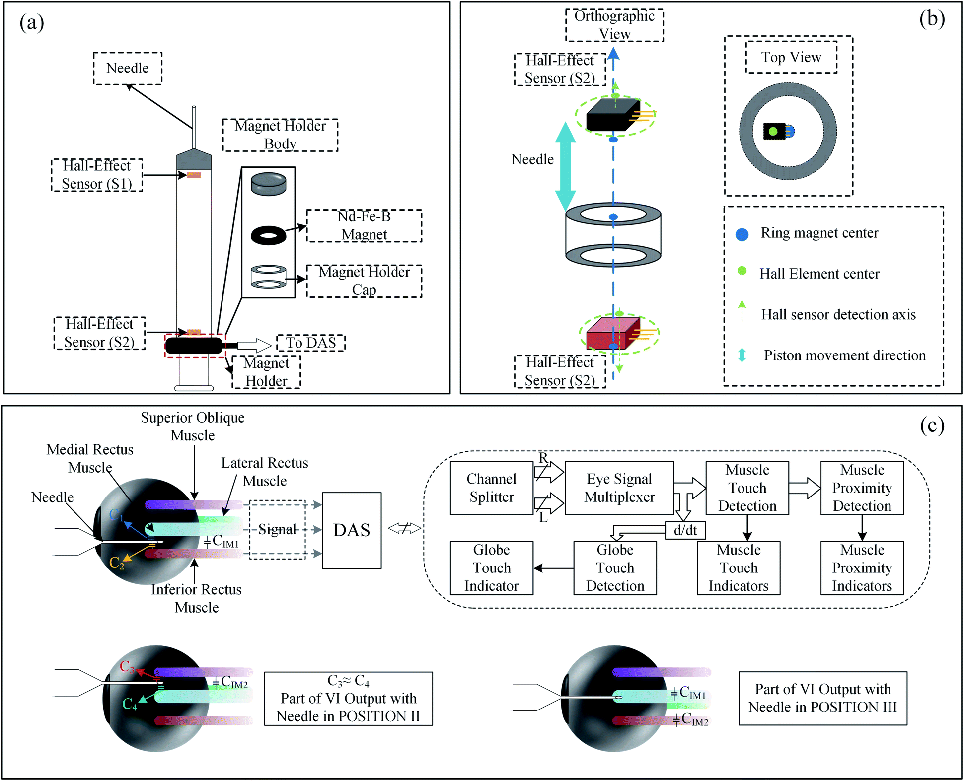 | ||
| Fig. 11 (a) Syringe assembly with dual Hall effect sensor;97 (b) Hall effect sensor assembly and ring magnet;97 (c) the schematic diagram of ophthalmic anesthesia training.98 | ||
4.3 Application III: characterizing soft biological material
Nowadays, more and more researchers are paying attention to minimally invasive surgery (MIS). The MIS helps surgeons perform delicate interventions, and provides patients with more comfort by reducing pain, blood loss and hospitalization. The experience of MIS is so strict that only few people can perform MIS. In order to reduce the difficulty of minimally invasive surgery, researchers have developed many auxiliary methods. A new generation of force detection systems has been formed through combining state-of-the-art Hall sensors, magnets and flexible membranes, as shown in Fig. 12(a). The distance between the magnet and the sensor is changed with the applied force on the flexible membrane due to distortion. When an external force acts on the force sensor, the film deflects, causing the permanent magnet to change its position. This causes the distance between the Hall sensor and the permanent magnet to change, and the magnetic field intensity read by the sensor increases. The increase of the magnetic field causes the Hall sensor to produce voltage changes. Once the sensor is calibrated, these voltages can be converted into perceived force. The system could then be utilized to detect forces on the tissue and distinguish different soft biological materials. As a good example, Chatzipirpiridis et al. have adopted a Hall sensor (A1389, Allegro) to build a new system to verify functions on the tissues.100 Subsequently, they miniaturized the system,104 as shown in Fig. 12(b). The internal temperature compensation circuit of the system reduces intrinsic sensitivity drift. In addition, a small signal high gain amplifier and a low impedance output are integrated into the sensor integrated circuit. Moreover, Chathuranga et al. have implemented 3 Hall sensors (SS495A, Honeywell) to build a 3-axis force system,101 as shown in Fig. 12(c). In the same year, 3 Hall sensors (AS5510, Allegro) were performed by Singal et al. to detect various soft biological materials,102 as shown in Fig. 12(d). The detection system they designed can simultaneously measure the strength of the x, y, and z dimensions. Overcoming the limitations of ergonomics, it can reach organs and tissues that are difficult to reach by traditional surgery. More recently, Backman et al. built a uniaxial tensile tester platform by using a Hall sensor (EQ-730L, AKM) as a force sensor,103 as shown in Fig. 12(e). This platform can help patients carry out targeted rehabilitation training.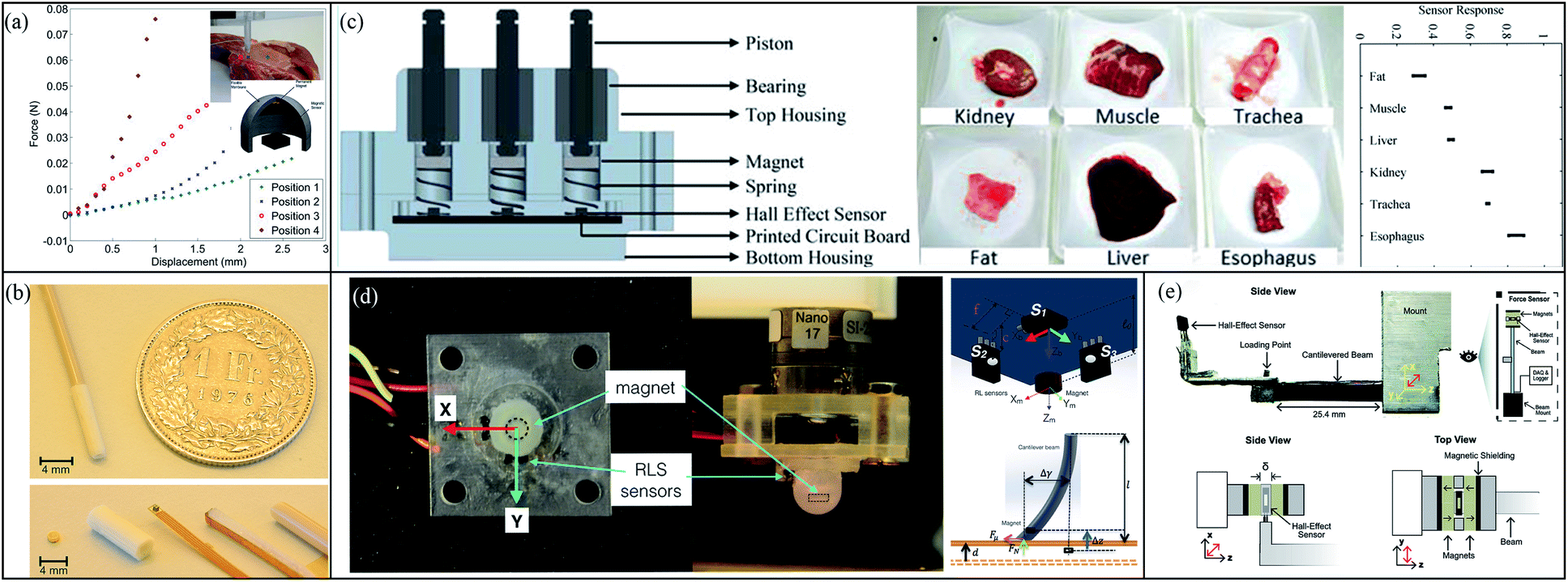 | ||
| Fig. 12 (a) Four different points in tissue are detected by using a force detection instrument consisting of Hall-effect sensor, magnet and flexible membrane;100 (b) miniaturized force detection instrument;100 (c) 3 Hall-effect sensors build 3-axis force detection instrument used for characterized different tissue;101 (d) using 3 Hall-effect sensor build force sensor for distinguishing biological tissue;102 (e) A uniaxial tensile tester by using Hall-effect sensor system as force sensor.103 | ||
4.4 Application IV: assisting MRI
Exposure to high electrostatic, magnetic fields during MRI examinations has a significant impact on the human. However, it is very necessary to use MRI to detect the cause of the disease. To reduce the impact of MRI on people as much as possible, more and more people are paying attention. In an MRI-guided surgery, Schell et al. utilized a 3-axis Hall sensor for the position detection of surgical tools.105–107 The use of hall sensors provides a new approach for the development of MRI-compatible real-time magnetic tracking systems that can be integrated into MR-guided minimally invasive surgical tools. Subsequently, Yamaguchi et al. installed a Hall sensor (THM1176-HF, Metrolab) in the cap for the magnetic field detection to avoid a strong magnetic field in the laboratory as long-term use.108,109 The hall voltage measured during the measurement is positively correlated with the local magnetic field, and since the gradients of all switches during the imaging sequence are predetermined, the spatial position of the sensor can be calculated from the hall voltage measured. Occupational exposure to high static magnetic fields (SMF) during magnetic resonance imaging (MRI) has been shown to be hazardous to health. As a similar purpose, Delmas et al. used a 3-aixs Hall sensor (CY-SJ362A) to build a new system to monitor static magnetic fields in the MRI.109 Data collection begins each time an object enters the scanner room, and ends when the object leaves the room.4.5 Other applications
In addition to the above applications, Hasenkamp et al. designed a smart system to assist degenerative diseases treatments. A Hall sensor (HW-322B, AKM) is adopted as a displacement sensor to measure displacements of the distractor. Moreover, Ruiz et al. built a microdrive.110 It could study neural activities of small animals such as birds and rates and rats. Similarly, a Hall sensor (A1324, Allegro) with the ultra-high resolution (few nanometers) was implemented to determine the positions of electrodes within the rat brain, avoiding a neutral signal loss. Besides Mayer et al. employed a handheld medical drilling system by using a Hall sensor to detect the breakthrough signals.111 Furthermore, Kreutzer et al. utilized a Hall sensor (SS411A, Honeywell) as a flow meter to monitor fluid intakes for dehydration prevention, especially for the elderly.112 It is worth mentioning that a Hall sensor (MLX90333, Melexis) has been used as position and orientation sensors to measure human mandible for assistance of obstructive sleep apnea treatments.113 In addition, Shokrollahi et al. built a robot haptic system based on a magnetorheological fluid method for the sensor disposable, cheap and indirect system for pressure measurements.114 surgery assistance. Hall sensor (TLE4990, Infineon), as a force sensor, was indirectly employed to eliminate device undesirable hysteresis behaviors. With a purpose of measuring the inner pressure of catheters, Accoto et al. adopted Hall sensors from Allegro (AS5000 and AS5510), as displacement sensors to measure the pressure indirectly.915 Conclusion
Benefiting from small physical size, low cost and CMOS integration, the Hall magnetic sensors have a great potential in biomedical applications. The increasing use of biomedicine has brought convenience to medical practitioners and reduced costs to patients. In MNP applications, Hall sensors can be used for a large area scanning to detect different diseases with an ultra-low price. Sensors for detecting MNPs, however, differ from common commercial integrated Hall sensors used in the automation field. Due to the small size and signals of the MNPs, it is a very challenging task for designers to capture signals and resolve the non-ideal factors. The Hall sensors are now widely used for the MNP detections in the research and development phases. The application of Hall sensor in biomedicine is very extensive. This article only lists a few typical applications such as medical training and detection. With the increased sensitivity of Hall sensors, it is believed that it can be used in the future for more sophisticated substance detection and laboratory equipment. Other applications involve the assistance of biomedical training or detection.Conflicts of interest
There are no conflicts to declare.Acknowledgements
The work of Hua Fan was supported by the National Natural Science Foundation of China (NSFC) under Grant 61771111, supported by Sichuan Provincial Science and Technology Important Projects under Grant 19ZDYF2863, Supported by the Open Foundation of State Key Laboratory of Electronic Thin Films and Integrated Devices under Grant KFJJ202006. The work of Quanyuan Feng was supported by the Major Project of the National Natural Science Foundation of China (NSFC) uner grant 62090012, supported by the National Natural Science Foundation of China (NSFC) under Grant 61531016, supported by Sichuan Provincial Science and Technology Important Projects under Grant 2018GZ0139, 2018ZDZX0148 and 2018GZDZX0001.Notes and references
- C. Wouters, V. Vranković, C. Rössler, S. Sidorov, K. Ensslin, W. Wegscheider and C. Hierold, Sens. Actuators, A, 2016, 237, 62–71 CrossRef CAS.
- C. Schott, R. Racz, F. Betschart and R. S. Popovic, IEEE SENSORS Conference, 2002, pp. 911–915 Search PubMed.
- T. Kaufmann, D. Kopp, M. Kunzelmann, P. Ruther and O. Paul, IEEE SENSORS Conference, 2011, pp. 440–443 Search PubMed.
- H. Heidari, S. Zuo, A. Krasoulis and K. Nazarpour, 2018 40th Annual International Conference of the IEEE Engineering in Medicine and Biology Society (EMBC), 2018, pp. 2116–2119 Search PubMed.
- K. Enpuku, K. Inoue, K. Soejima, K. Yoshinaga, H. Kuma and N. Hamasaki, IEEE Trans. Appl. Supercond., 2005, 15, 660–663 CrossRef CAS.
- C. Tamanaha, S. Mulvaney, J. Rife and L. Whitman, Biosens. Bioelectron., 2008, 24, 1–13 CrossRef CAS.
- A. Tsukamoto, K. Saitoh, D. Suzuki, N. Sugita, Y. Seki, A. Kandori, K. Tsukada, Y. Sugiura, S. Hamaoka, H. Kuma, N. Hamasaki and K. Enpuku, IEEE Trans. Appl. Supercond., 2005, 15, 656–659 CrossRef CAS.
- J. Lenz and S. Edelstein, IEEE Sens. J., 2006, 6, 631–649 Search PubMed.
- S. I. Farrag, IEEE Conference on Biomedical Engineering and Sciences (IECBES), 2014, pp. 612–617 Search PubMed.
- M. E. Ladd, L. Umutlu, S. Maderwald, S. Kinner, S. Orzada, K. Nassenstein, I. Brote, H. Quick, L. Schaefer, S. Ladd, G. Antoch, O. Kraff, A. Bitz and T. Lauenstein, IEEE Int. Symposium on Biomedical Imaging: From Nano to Macro, 2010, pp. 572–572 Search PubMed.
- S. Yamaguchi-Sekino, M. Sekino and T. Nakai, IEEE Trans. Magn., 2015, 51, 1–4 Search PubMed.
- H. Lee, E. Sun, D. Ham and R. Weissleder, Nat. Med., 2008, 14, 869–874 CrossRef CAS.
- N. Sun, T. Yoon, H. Lee, W. Andress, R. Weissleder and D. Ham, IEEE J. Solid-State Circuits, 2011, 46, 342–352 Search PubMed.
- J. Llandro, J. Palfreyman, A. Ionescu and C. Barnes, Med. Biol. Eng. Comput., 2010, 48, 977–998 CrossRef CAS.
- M. Lucas and E. Riedo, Rev. Sci. Instrum., 2012, 83, 061101 CrossRef.
- P.-H. Kuo, J.-C. Kuo, H.-T. Hsueh, J.-Y. Hsieh, Y.-C. Huang, T. Wang, Y.-H. Lin, C.-T. Lin, Y.-J. Yang and S.-S. Lu, IEEE Transactions on Biomedical Circuits and Systems, 2015, 9, 790–800 Search PubMed.
- D. A. Hall, R. S. Gaster, S. J. Osterfeld, K. Makinwa, S. X. Wang and B. Murmann, 2011 Symposium on VLSI Circuits-Digest of Technical Papers, 2011, pp. 174–175 Search PubMed.
- W. Lee, S. Joo, S. U. Kim, K. Rhie, J. Hong, K.-H. Shin and K. H. Kim, Appl. Phys. Lett., 2009, 94, 153903 CrossRef.
- P. Liu, K. Skucha, M. Megens and B. Boser, IEEE Trans. Magn., 2011, 47, 3449–3451 Search PubMed.
- A. Sandhu, H. Sanbonsugi, I. Shibasaki, M. Abe and H. Handa, Jpn. J. Appl. Phys., 2004, 43, L868 CrossRef CAS.
- K. Skucha, P. Liu, M. Megens, J. Kim and B. Boser, 2011, 16th International Solid-State Sensors, Actuators and Microsystems Conference, 2011, pp. 1833–1836 Search PubMed.
- H. Heidari, U. Gatti and F. Maloberti, 11th Conference on Ph. D. Research in Microelectronics and Electronics (PRIME), 2015, pp. 330–333 Search PubMed.
- Z. Yin, E. Bonizzoni and H. Heidari, IEEE Journal of Electromagnetics, RF and Microwaves in Medicine and Biology, 2018, 2, 179–185 Search PubMed.
- I. Ennen, D. Kappe, T. Rempel, C. Glenske and A. Hütten, Sensors, 2016, 16, 904 CrossRef.
- D. R. Baselt, G. U. Lee, M. Natesan, S. W. Metzger, P. E. Sheehan and R. J. Colton, Biosens. Bioelectron., 1998, 13, 731–739 CrossRef CAS.
- T. Costa, F. A. Cardoso, J. Germano, P. P. Freitas and M. S. Piedade, IEEE Transactions on Biomedical Circuits and Systems, 2017, 11, 988–1000 Search PubMed.
- D. Hall, R. Gaster, T. Lin, S. Osterfeld, S. Han, B. Murmann and S. Wang, Biosens. Bioelectron., 2010, 25, 2051–2057 CrossRef CAS.
- G. Rizzi, J.-R. Lee, P. Guldberg, M. Dufva, S. X. Wang and M. F. Hansen, Biosens. Bioelectron., 2017, 93, 155–160 CrossRef CAS.
- J. Xu, Q. Li, W. Zong, Y. Zhang and S. Li, J. Magn. Magn. Mater., 2016, 417, 25–29 CrossRef CAS.
- S. Zuo, K. Nazarpour and H. Heidari, IEEE Electron Device Lett., 2018, 39, 1784–1787 CAS.
- A. Tanwear, X. Liang, Y. Liu, A. Vuckovic, R. Ghannam, T. Böhnert, E. Paz, P. P. Freitas, R. Ferreira and H. Heidari, IEEE Transactions on Biomedical Circuits and Systems, 2020, 14, 1299–1310 Search PubMed.
- S. Zuo, H. Heidari, D. Farina and K. Nazarpour, Adv. Mater. Technol., 2020, 5, 2000185 CrossRef.
- P. M. Drljača, P. Kejik, F. Vincent, D. Piguet, F. Gueissaz and R. S. Popović, Sens. Actuators, A, 2004, 110, 236–241 CrossRef.
- C.-C. Lu, W.-S. Huang, Y.-T. Liu and J.-T. Jeng, IEEE Trans. Magn., 2011, 47, 3752–3755 Search PubMed.
- J. Nordling, R. L. Millen, H. A. Bullen, M. D. Porter, M. Tondra and M. C. Granger, Anal. Chem., 2008, 80, 7930–7939 CrossRef CAS.
- A. Weddemann, I. Ennen, A. Regtmeier, C. Albon, A. Wolff, K. Eckstädt, N. Mill, M. K.-H. Peter, J. Mattay and C. Plattner, et al., Beilstein J. Nanotechnol., 2010, 1, 75–93 CrossRef CAS.
- A. Bernieri, G. Betta, L. Ferrigno and M. Laracca, IEEE Sens. J., 2013, 13, 4513–4521 Search PubMed.
- J. Li, X. Zhang, J. Shi, H. Heidari and Y. Wang, IEEE Sens. J., 2019, 19, 11819–11827 Search PubMed.
- H. Heidari and V. Nabaei, in Magnetic Sensors Based on Hall Effect, John Wiley & Sons, Ltd, 2019, ch. 2, pp. 33–56 Search PubMed.
- V. Nabaei, R. Chandrawati and H. Heidari, Biosens. Bioelectron., 2018, 103, 69–86 CrossRef CAS.
- E. Ramsden, Hall-effect sensors: theory and application, Elsevier, 2011 Search PubMed.
- A. Hassibi, S. Zahedi, R. Navid, R. W. Dutton and T. H. Lee, J. Appl. Phys., 2005, 97, 084701 CrossRef.
- H. Heidari, E. Bonizzoni, U. Gatti and F. Maloberti, 2014 IEEE International Symposium on Circuits and Systems (ISCAS), 2014, pp. 678–681 Search PubMed.
- H. Heidari, U. Gatti, E. Bonizzoni and F. Maloberti, Proceedings of the 2013 9th Conference on Ph. D. Research in Microelectronics and Electronics (PRIME), 2013, pp. 325–328 Search PubMed.
- H. Heidari, E. Bonizzoni, U. Gatti and F. Maloberti, IEEE Transactions on Circuits and Systems I: Regular Papers, 2015, 62, 1270–1278 Search PubMed.
- H. Heidari, E. Bonizzoni, U. Gatti, F. Maloberti and R. Dahiya, IEEE Sens. J., 2016, 16, 8736–8743 CAS.
- R. Popović, Sens. Actuators, 1989, 17, 39–53 CrossRef.
- A. Bilotti, G. Monreal and R. Vig, IEEE J. Solid-State Circuits, 1997, 32, 829–836 CrossRef.
- P.-A. Besse, G. Boero, M. Demierre, V. Pott and R. Popovic, Appl. Phys. Lett., 2002, 80, 4199–4201 CrossRef CAS.
- W. de Jager and G. T. Rijkers, Methods, 2006, 38, 294–303 CrossRef CAS.
- F. Conzuelo, M. Gamella, S. Campuzano, A. J. Reviejo and J. M. Pingarrón, Anal. Chim. Acta, 2012, 737, 29–36 CrossRef CAS.
- W.-Y. Chung, A. A. Silverio, R. F. Ramezani, J.-Y. Lai and A. A. Silverio, IEEE Region 10 Conference - TENCON, 2017, pp. 1593–1597 Search PubMed.
- C. Menolfi and Q. Huang, IEEE J. Solid-State Circuits, 1997, 32, 968–976 CrossRef.
- S. M. Dadfar, K. Roemhild, N. I. Drude, S. von Stillfried, R. Knüchel, F. Kiessling and T. Lammers, Adv. Drug Delivery Rev., 2019, 138, 302–325 CrossRef CAS.
- N. Bhalla, D. W. Y. Chung, Y.-J. Chang, K. J. S. Uy, Y. Y. Ye, T.-Y. Chin, H. C. Yang and D. G. Pijanowska, Micromachines, 2013, 4, 257–271 CrossRef.
- G. Mihajlović, P. Xiong, S. von Molnár, K. Ohtani, H. Ohno, M. Field and G. J. Sullivan, Appl. Phys. Lett., 2005, 87, 112502 CrossRef.
- S. Gambini, K. Skucha, P. P. Liu, J. Kim and R. Krigel, IEEE J. Solid-State Circuits, 2012, 48, 302–317 Search PubMed.
- T. Ishikawa and S. Tanaka, 2017 19th International Conference on Solid-State Sensors, Actuators and Microsystems (TRANSDUCERS), 2017, pp. 1612–1615 Search PubMed.
- B. Cao, K. Wang, H. Xu, Q. Qin, J. Yang, W. Zheng, Q. Jin and D. Cui, Sens. Actuators, A, 2020, 112130 CrossRef CAS.
- D. Issadore, Y. Park, H. Shao, C. Min, K. Lee, M. Liong, R. Weissleder and H. Lee, Lab Chip, 2014, 14, 2385–2397 RSC.
- O. Kazakova, J. Gallop, G. Perkins and L. Cohen, Appl. Phys. Lett., 2007, 90, 162502 CrossRef.
- P. Manandhar, K.-S. Chen, K. Aledealat, G. Mihajlović, C. S. Yun, M. Field, G. J. Sullivan, G. F. Strouse, P. B. Chase and S. von Molnár, et al., Nanotechnology, 2009, 20, 355501 CrossRef.
- G. Mihajlović, K. Aledealat, P. Xiong, S. Von Molnar, M. Field and G. J. Sullivan, Appl. Phys. Lett., 2007, 91, 172518 CrossRef.
- M. Nikitin, M. Torno, H. Chen, A. Rosengart and P. Nikitin, J. Appl. Phys., 2008, 103, 07A304 CrossRef.
- J. B. Haun, N. K. Devaraj, S. A. Hilderbrand, H. Lee and R. Weissleder, Nat. Nanotechnol., 2010, 5, 660–665 CrossRef CAS.
- G. Landry, M. Miller, B. Bennett, M. Johnson and V. Smolyaninova, Appl. Phys. Lett., 2004, 85, 4693–4695 CrossRef CAS.
- C. Tamanaha, S. Mulvaney, J. Rife and L. Whitman, Biosens. Bioelectron., 2008, 24, 1–13 CrossRef CAS.
- O. Florescu, K. Wang, P. Au, J. Tang, E. Harris, P. R. Beatty and B. E. Boser, J. Appl. Phys., 2010, 107, 054702 CrossRef.
- J.-C. Kuo, P.-H. Kuo, H.-T. Hsueh, C.-W. Ma, C.-T. Lin, S.-S. Lu and Y.-J. Yang, 2014 IEEE 27th International Conference on Micro Electro Mechanical Systems (MEMS), 2014, pp. 809–812 Search PubMed.
- O. Florescu, M. Mattmann and B. Boser, Fully integrated detection of single magnetic beads in complementary metal-oxide-semiconductor, 2008 Search PubMed.
- J. Kaur, K. V. Singh, A. H. Schmid, G. C. Varshney, C. R. Suri and M. Raje, Biosens. Bioelectron., 2004, 20, 284–293 CrossRef CAS.
- K. Skucha, S. Gambini, P. Liu, M. Megens, J. Kim and B. Boser, IEEE ASME J. Microelectromech. Syst., 2013, 22, 1327–1338 CAS.
- Y. Zheng, N. Shang, P. S. Haddad and M. Sawan, IEEE transactions on biomedical circuits and systems, 2015, 10, 477–486 Search PubMed.
- J. Mok, M. N. Mindrinos, R. W. Davis and M. Javanmard, Proc. Natl. Acad. Sci. U.S.A., 2014, 111, 2110–2115 CrossRef CAS.
- G. Proczek, A.-L. Gassner, J.-M. Busnel and H. H. Girault, Anal. Bioanal. Chem., 2012, 402, 2645–2653 CrossRef CAS.
- P. P. Liu, K. Skucha, Y. Duan, M. Megens, J. Kim, I. I. Izyumin, S. Gambini and B. Boser, IEEE J. Solid-State Circuits, 2012, 47, 1056–1064 Search PubMed.
- K. W. Kim, V. Reddy, S. R. Torati, X. H. Hu, A. Sandhu and C. G. Kim, Lab Chip, 2015, 15, 696–703 RSC.
- L. Di Michele, C. Shelly, P. de Marco, P. See, D. Cox and O. Kazakova, J. Appl. Phys., 2011, 110, 063916 CrossRef.
- H. Wang, Y. Chen, A. Hassibi, A. Scherer and A. Hajimiri, 2009 IEEE International Solid-State Circuits Conference-Digest of Technical Papers, 2009, pp. 438–439 Search PubMed.
- F. W. Østerberg, G. Rizzi, T. Z. G. de la Torre, M. Strömberg, M. Strømme, P. Svedlindh and M. Hansen, Biosens. Bioelectron., 2013, 40, 147–152 CrossRef.
- A. Henriksen, B. T. Dalslet, D. Skieller, K. Lee, F. Okkels and M. F. Hansen, Appl. Phys. Lett., 2010, 97, 013507 CrossRef.
- A. Persson, R. S. Bejhed, H. Nguyen, K. Gunnarsson, B. T. Dalslet, F. W. Oesterberg, M. F. Hansen and P. Svedlindh, Sens. Actuators, A, 2011, 171, 212–218 CrossRef CAS.
- P. T. K. Loan, D. Wu, C. Ye, X. Li, V. T. Tra, Q. Wei, L. Fu, A. Yu, L.-J. Li and C.-T. Lin, Biosens. Bioelectron., 2018, 99, 85–91 CrossRef CAS.
- T. Ookubo, Y. Inoue, D. Kim, H. Ohsaki, Y. Mashiko, M. Kusakabe and M. Sekino, Electron. Commun. Jpn., 2016, 99, 13–21 CrossRef.
- A. Kuwahata, S. Chikaki, A. Ergin, M. Kaneko, M. Kusakabe and M. Sekino, AIP Adv., 2017, 7, 056720 CrossRef.
- P. Ripka and M. Janosek, IEEE Sens. J., 2010, 10, 1108–1116 Search PubMed.
- A. Sandhu, Y. Kumagai, A. Lapicki, S. Sakamoto, M. Abe and H. Handa, Biosens. Bioelectron., 2007, 22, 2115–2120 CrossRef CAS.
- H. Heidari and V. Nabaei, Magnetic Sensors for Biomedical Applications, John Wiley & Sons, 2019 Search PubMed.
- P. Ripka and M. Janosek, IEEE SENSORS Conference, 2008, pp. 1–4 Search PubMed.
- J. H. Kratzer, Magneto-optic properties of II-VI semiconductor quantum dots, Rensselaer Polytechnic Institute, 2005 Search PubMed.
- D. Accoto, M. Rossini, S. Valentini and I. Portaccio, IEEE Sens. J., 2018, 18, 3564–3571 Search PubMed.
- P. Nabeel, J. Joseph and M. Sivaprakasam, 36th Annual Int. Conference of the IEEE Engineering in Medicine and Biology Society, 2014, pp. 1953–1956 Search PubMed.
- P. Nabeel, J. Joseph and M. Sivaprakasam, IEEE transactions on biomedical circuits and systems, 2017, 11, 1065–1076 Search PubMed.
- D.-H. Nam, W.-B. Lee, Y.-S. Hong and S.-S. Lee, Sensors, 2013, 13, 4714–4723 CrossRef.
- K.-H. Kim and S.-S. Lee, New J. Phys, 2013, 63, 1135–1139 Search PubMed.
- D.-H. Lee, Y.-S. Hong and S.-S. Lee, J. Korean Magn. Soc., 2013, 23, 135–143 CrossRef.
- B. Mukherjee, B. George and M. Sivaprakasam, 2013 35th Annual International Conference of the IEEE Engineering in Medicine and Biology Society (EMBC), 2013, pp. 4734–4737 Search PubMed.
- B. Mukherjee, B. George and M. Sivaprakasam, IEEE Trans. Instrum. Meas., 2014, 63, 1153–1162 Search PubMed.
- K. Borvorntanajanya and J. Suthakorn, 2018 IEEE International Conference on Robotics and Automation (ICRA), 2018, pp. 1–6 Search PubMed.
- G. Chatzipirpiridis, P. Erne, O. Ergeneman, S. Pané and B. J. Nelson, 37th Annual International Conference of the IEEE Engineering in Medicine and Biology Society (EMBC), 2015, pp. 7970–7973 Search PubMed.
- D. S. Chathuranga, Z. Wang, Y. Noh, T. Nanayakkara and S. Hirai, 37th Annual Int. Conference of the IEEE Engineering in Medicine and Biology Society (EMBC), 2015, pp. 5521–5524 Search PubMed.
- K. Singal, R. Rajamani, M. Ahmadi, A. S. Sezen and J. E. Bechtold, IEEE Trans. Biomed. Eng., 2014, 62, 426–437 Search PubMed.
- D. E. Backman, B. L. LeSavage and J. Y. Wong, J. Biomech., 2017, 51, 118–122 CrossRef.
- G. Chatzipirpiridis, S. Gervasoni, F. Berlinger, O. Ergeneman, S. Pané and B. Nelson et al., Int. Conference on Solid-State Sensors, Actuators and Microsystems (TRANSDUCERS), 2015, pp. 1727–1730 Search PubMed.
- J.-B. Schell, L. Cuvillon, D. Gounot, E. Breton, J.-B. Kammerer, L. Hébrard and M. de Mathelin, SENSORS, 2013 IEEE, 2013, pp. 1–4 Search PubMed.
- H. Fan, S. Li, V. Nabaei, Q. Feng and H. Heidari, IEEE Sens. J., 2020, 20, 9919–9927 Search PubMed.
- H. Fan, S. Li, Y. Cen, Q. Feng and H. Heidari, IEEE 63rd Int. Midwest Symposium on Circuits and Systems (MWSCAS), 2020, pp. 893–896 Search PubMed.
- S. Yamaguchi-Sekino, T. Nakai, S. Imai, S. Izawa and T. Okuno, Bioelectromagnetics, 2014, 35, 70–75 CrossRef.
- A. Delmas, L. Belguerras, N. Weber, F. Odille, C. Pasquier, J. Felblinger and P.-A. Vuissoz, Bioelectromagnetics, 2018, 39, 108–119 CrossRef CAS.
- A. Caballero-Ruiz, L. I. Garcia-Beltran, L. Ruiz-Huerta and F. Heredia-Lopez, Int. Conference on Mechatronics, Electronics and Automotive Engineering, 2014, pp. 168–172 Search PubMed.
- M. Mayer, H. H. Lin, Y. H. Peng, P. Y. Lee and M. L. Wang, Int. Symposium on Computer, Consumer and Control, 2014, pp. 958–961 Search PubMed.
- J. F. Kreutzer, J. Deist, C. M. Hein and T. C. Lueth, IEEE Int. Conference on Wearable and Implantable Body Sensor Networks (BSN), 2016, pp. 1–6 Search PubMed.
- M. van der Schoot, S. Verwulgen, J. Van Goey, K. Keignaert, O. M. Vanderveken and M. J. Braem, Conference on Design of Circuits and Integrated Systems (DCIS), 2016, pp. 1–5 Search PubMed.
- E. Shokrollahi, A. A. Goldenberg, J. M. Drake, K. W. Eastwood and M. Kang, 39th Annual Int. Conference of the IEEE Engineering in Medicine and Biology Society (EMBC), 2017, pp. 3926–3929 Search PubMed.
| This journal is © The Royal Society of Chemistry 2021 |