
Universal host materials for red, green and blue high-efficiency single-layer phosphorescent organic light-emitting diodes†
Fabien
Lucas
 a,
Cassandre
Quinton
a,
Sadiara
Fall
b,
Thomas
Heiser
b,
Denis
Tondelier
c,
Bernard
Geffroy
cd,
Nicolas
Leclerc
e,
Joëlle
Rault-Berthelot
a and
Cyril
Poriel
*a
a,
Cassandre
Quinton
a,
Sadiara
Fall
b,
Thomas
Heiser
b,
Denis
Tondelier
c,
Bernard
Geffroy
cd,
Nicolas
Leclerc
e,
Joëlle
Rault-Berthelot
a and
Cyril
Poriel
*a
aUniv Rennes, CNRS, ISCR-UMR CNRS 6226, F-35000 Rennes, France. E-mail: cyril.poriel@univ-rennes1.fr
bLaboratoire ICube, Université de Strasbourg, UMR CNRS 7357, 67087 Strasbourg, France
cLPICM, CNRS, Ecole Polytechnique, Institut Polytechnique de Paris, route de Saclay, 91128 Palaiseau, France
dUniversité Paris-Saclay, CEA, CNRS, NIMBE, LICSEN, 91191, Gif-sur-Yvette, France
eInstitut de Chimie et Procédés pour l’Énergie, l’Environnement et la Santé (ICPEES), UMR CNRS 7515, 67087 Strasbourg, France
First published on 4th November 2020
Abstract
Simplifying the structure of Organic Light-Emitting Diodes (OLEDs) has been for the last twenty years the purpose of many studies. However, despite these efforts, only a few materials provide high efficiency devices. We report herein efficient design strategies to construct universal host materials for red, green and blue Single-Layer Phosphorescent OLEDs (SL-PhOLEDs). The three materials investigated, SPA-2,7-F(POPh2)2, SPA-3,6-F(POPh2)2 and SPA-2-FPOPh2, have been synthesized via an efficient approach and are constructed on the association of an electron rich phenylacridine unit connected by a spiro carbon atom to three different electron-deficient diphenylphosphineoxide-substituted fluorenes. Electrochemical, spectroscopic, thermal and transport properties are discussed. The position (C2 and C7 vs. C3 and C6) and the number (1 vs. 2) of diphenylphosphineoxide units on the fluorene backbone have been particularly studied to highlight the best combination in term of device performance. Red, green and blue SL-PhOLEDs (RGB SL-PhOLEDs) have been fabricated and characterized and their performances discussed. Of particular interest, we managed to reach a FIr6-based SL-PhOLED (with SPA-2-FPOPh2) possessing an external quantum efficiency of 9.1% and a low threshold voltage (below 3 V). As far as we know, this is the first example of SL-PhOLED using this blue phosphorescent emitter. On the other hand, with notably a very high external quantum efficiency of 18% with FIrpic as sky blue emitter, SPA-2,7-F(POPh2)2 displays the highest overall performance in the series and the highest overall performance ever reported for RGB SL-PhOLEDs using a universal host. This not only shows that the association of phenylacridine and diphenylphosphineoxide units fulfils the required criteria for an universal host for high efficiency SL-PhOLEDs but also highlights that the arrangement of these fragments drives the device performance.
Introduction
The development of efficient organic host matrices for the emissive layer (EML) of Phosphorescent Organic Light-Emitting Diodes (PhOLEDs)1 is at the origin of the fantastic progresses made by this technology in the last twenty years.1–4 The role played by the host matrix is crucial as it should prevent energy back transfers from the guest emitter to the host and favour the confinement of excitons. Today, the rational design of host materials for guest phosphors has allowed to reach very high-efficiency red, green or blue PhOLEDs (with external quantum efficiency EQE > 25%).5–18 However, all these are multi-layer devices, which are constituted of a stack of organic layers in order to improve the injection, transport and recombination of charges within the EML. To reduce the cost and the environmental footprint of the OLED technology, simplifying the multi-layer structure is one interesting direction for the future.19 The so-called Single-Layer PhOLEDs (SL-PhOLEDs), the simplest device only made of the electrodes and the EML, have thus stimulated a strong interest for the last fifteen years. However, reaching high efficiency SL-PhOLEDs of all the colours (red,20–25 yellow,21,26,27 orange,26,27 green,21,23,26,28–34 blue23,24,33,35–37 and white38) is a difficult task as removing the functional organic layers of a PhOLED stack leads to a dramatic decrease of the performance. Simplifying the PhOLED technology goes also through the use of high-efficiency universal materials which can efficiently host red (R), green (G) and blue (B) phosphors.Some examples have shown that, with rational designs, the host material can perform the job of the numerous functional organic layers used in multi-layer structures. Thus, an ideal host material for RGB SL-PhOLEDs should fulfil several criteria: (i) a high triplet state energy ET > 2.7 eV to confine the triplet excitons within phosphorescent guest, (ii) HOMO/LUMO energy levels well adapted to the electrode Fermi levels allowing efficient charge injection, (iii) good and well balanced mobilities of electrons and holes (ambipolar character) in order to compensate for the absence of electron/hole transporting layers,39 and (iv) thermal and morphological stabilities to extend the lifetime of the devices. These four criteria can be fulfilled by the careful association of an electron-rich and an electron-deficient unit within a single molecule. However, while some examples of very high performance RGB multi-layer PhOLEDs have been recently described,5,18,40–45 RGB SL-PhOLEDs remain very rarely reported in literature.23,24
Thus, in the present work, we consider the simplest EML of a SL-PhOLED only constituted of one host material and the phosphor. The literature also reports other strategies to reach high efficiency SL-PhOLEDs such as a host/co-host combination in the EML. Despite high EQE have been obtained, this strategy46–50 requires several molecules instead of only one in conventional SL-PhOLEDs. Other simplified device architectures have also been used in the literature, with one or two undoped regions of the host material on each side of the EML.51,52
Recently, we have shown that phenylacridine/diphenylphosphine oxide association in SPA-2,7-F(POPh2)2 (see structure in Scheme 1) is very efficient to reach high performance green and blue SL-PhOLEDs.33 In the present work, we report a structure properties relationship study involving three bipolar hosts (SPA-2,7-F(POPh2)2,33SPA-3,6-F(POPh2)2 and SPA-2-FPOPh2) constructed on the association of the electron-rich phenylacridine and the electron-poor diphenylphosphine oxide. The position (C2 and C7 vs. C3 and C6) and the number (1 vs. 2) of diphenylphosphineoxide units on the fluorene backbone have been studied in detail to highlight the best combination in term of device performance. Such studies are the foundation of organic electronics to reach high performance devices. Finally, RGB SL-PhOLEDs have been fabricated and characterized using four different emitters (red: bis(2-methyldibenzo[f,h]quinoxaline)(acetylacetonate)iridium(III)-Ir(MDQ)2(acac), green: tris[2-phenylpyridinato-C2,N]iridium(III)-Ir(ppy)3 and two blue emitters: bis(3,5-difluoro-2-(2-pyridyl)phenyl-(2-carboxypyridyl) iridium(III)-FIrpic and bis(2,4-difluorophenylpyridinato)-tetrakis(1-pyrazolyl)borate iridium(III)-FIr6), see characterization of iridium complexes in Table 2 and ESI†). It is important to mention that the blue emitter FIr6 investigated herein has been rarely used in literature (due to its high ET and the resulting difficulty to be hosted). Some examples are found for multi-layer PhOLEDs40,53,54 but as far as we know no example has been reported to date in SL-PhOLEDs using a single host (only one example exists and it involves a host:co-host system and displays low performance47). In this work, we manage to reach a promising FIr6-based SL-PhOLED (with SPA-2-FPOPh2) possessing an EQE of 9.1% and a low Von below 3 V. This may allow the development of blue SL-PhOLEDs with emission wavelengths shorter than those of the sky blue emitter Firpic. On the other hand, with notably a high EQE of 18% with FIrpic as sky blue emitter, SPA-2,7-F(POPh2)2 displays the highest overall performance in the series and demonstrates that high performance SL-PHOLEDs can be reach for all the colours with the same host material. This translates the efficiency of the association of phenylacridine and diphenylphosphineoxide units in the EML of RGB SL-PhOLEDs and its potential for the future.
 | ||
| Scheme 1 Synthesis of SPA-2,7-F(POPh2)2, SPA-3,6-F(POPh2)2 and SPA-2-FPOPh2 and molecular structure of model compound SPA-F. | ||
Synthesis
For potential industrial applications and to reduce the environmental footprint, the synthesis of a universal host material for a SL-PhOLED should (i) be short and high yielded, (ii) use inexpensive starting materials and (iii) avoid rare metal catalysts. The present target molecules have been synthesized following a versatile and efficient two-step route (Scheme 1). A lithium–bromine exchange was first performed on 2-bromophenyldiphenylamine followed by the trapping of the lithiated intermediate by the corresponding fluorenone, i.e. either 2,7-dibromofluorenone for SPA-2,7-F(POPh2)2, 3,6-dibromofluorenone for SPA-3,6-F(POPh2)2 or 2-bromofluorenone for SPA-2-FPOPh2. Spiro compounds SPA-2,7-FBr2, SPA-3,6-FBr2 and SPA-2-FBr were then obtained by cyclization (in HCl/AcOH media) of the corresponding fluorenols (not isolated) in a high yield of 72%, 86% and 95%. Adding n-BuLi to these platforms lead to a lithium–halogen exchange reaction providing the corresponding lithiated intermediates, which were trapped with chlorodiphenylphosphine to provide the corresponding diphenylphosphine compounds (not isolated), further oxidized in the presence of H2O2 to give SPA-2,7-F(POPh2)2, SPA-3,6-F(POPh2)2 or SPA-2-FPOPh2 with a yield of 79%, 44% and 73% respectively. Therefore, this synthetic approach is versatile, short, very efficient (overall yield of 57%, 38% and 69%), and low cost as it uses cheap starting materials (less than 0.5 € per g for 2-bromofluorenone, 2 € per g for 2,7-dibromofluorenone and 4 € per g for 3,6-dibromofluorenone, 8 € per g for 2-bromophenyldiphenylamine) and no palladium catalyst. It should be mentioned that SPA-2,7-FBr2, SPA-3,6-FBr2 and SPA-2-FBr are appealing functional platforms, on which can be easily attached many different molecular fragments of interest for organic electronics.In order to precisely study the impact of the incorporation of the electron-poor units within the three compounds, their properties will be compared to those of unsubstituted model compound spirophenylacridine-fluorene SPA-F (See molecular structure in the insert of Scheme 1).33 Note that SPA-2,7-F(POPh2)2 and SPA-3,6-F(POPh2)2 are positional isomers, a key concept in organic chemistry, more and more used in the design of organic semi-conductors for electronics55,56 (for Organic Field-Effect Transistors,57–59 OLEDs,60–63 or Organic Photovoltaics64).
The electrochemical properties of SPA-2,7-F(POPh2)2, SPA-3,6-F(POPh2)2, SPA-2-FPOPh2 and the model compound SPA-F have been investigated by cyclic voltammetry (CV) in CH2Cl2 for oxidation and in DMF for reduction (Fig. 1, top); potentials are given versus a saturated calomel electrode (SCE).
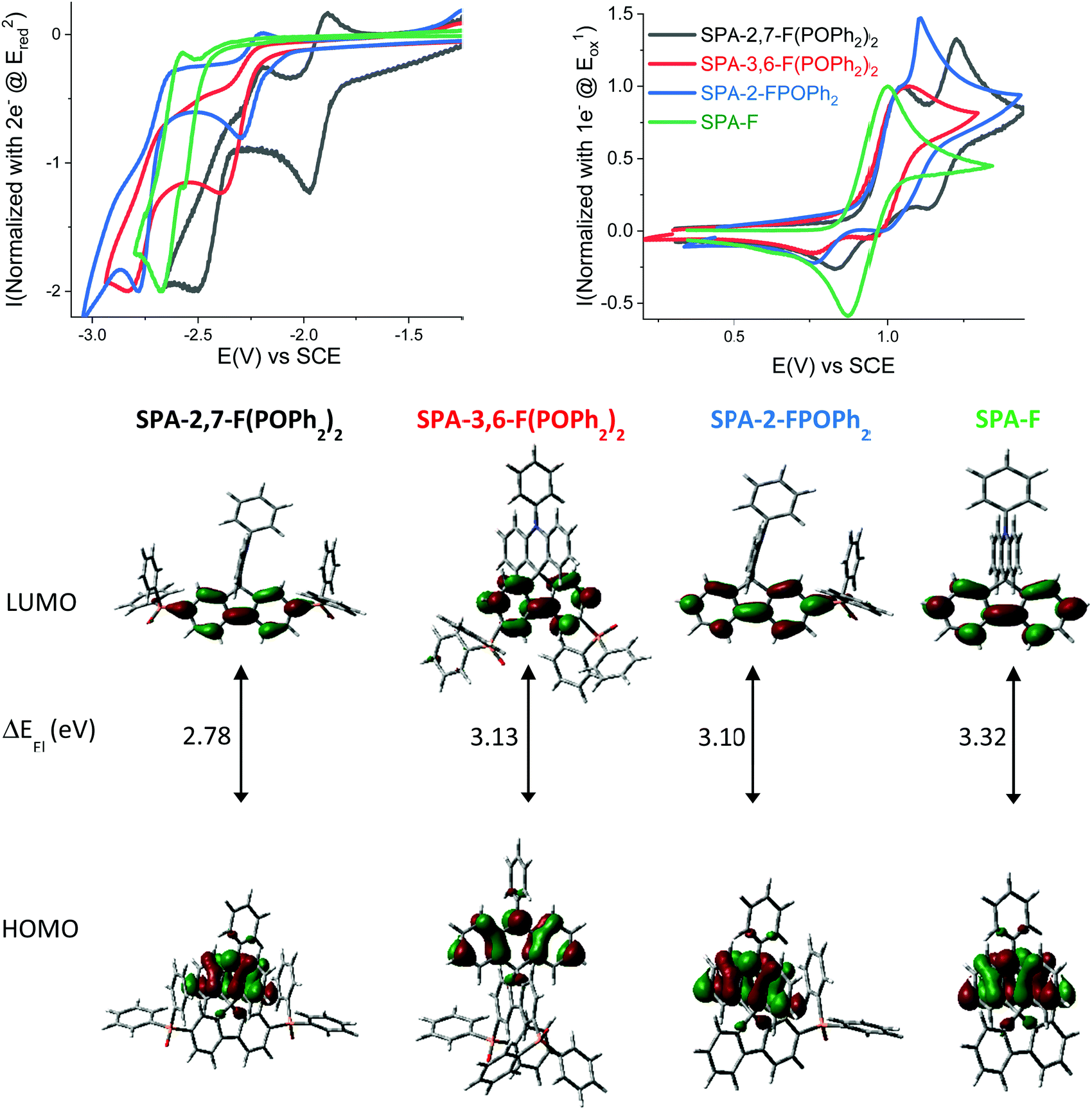 | ||
| Fig. 1 Top: Normalized cyclic voltammograms of SPA-2,7-F(POPh2)2 (black lines), SPA-3,6-F(POPh2)2 (red lines) and SPA-2-FPOPh2 (blue lines) and SPA-F (green lines) in the cathodic (left, DMF + Bu4NPF6 0.1 M) or the anodic (right, CH2Cl2 + Bu4NPF6 0.2 M) range. Sweep-rate: 100 mV s−1, platinum disk working electrode. Bottom: Frontier molecular orbitals LUMO and HOMO calculated by TD-DFT (b3lyp/6-311+G(d,p)), isovalue 0.04 [e Bohr−3]1/2. | ||
In oxidation, SPA-2,7-F(POPh2)2, SPA-3,6-F(POPh2)2 and SPA-2-FPOPh2 present three successive oxidation waves with maxima reported in Table 1 and detailed electrochemical studies presented in ESI.† For these three compounds, the first oxidation process is irreversible (at a sweep-rate of 100 mV s−1) with a maximum close to 1.05 V (Fig. 1, top-right). The model compound SPA-F, without any phosphine oxide attached, displays a different behaviour with a first reversible oxidation wave at 1.00 V, being therefore shifted by 50 mV (Fig. 1, top-right, green line) compared to the three phosphine oxide compounds. This indicates that the phosphine oxide fragments have an influence on the reversibility of the first oxidation wave and on its potential values. Indeed, despite the separation of the donor and the acceptor units by the spiro bridge, the oxidation of the phenylacridine is influenced by the nature of the electron poor bis(diphenylphosphineoxide)-fluorene unit and appears more difficult to oxidize than the model compound SPA-F. However, it is noteworthy to mention that the number and the position of the diphenylphosphine oxide units do not influenced significantly the oxidation of the phenylacridine unit as the SPA-2,7-F(POPh2)2, SPA-3,6-F(POPh2)2 and SPA-2-FPOPh2 compounds are oxidized at similar potential values (ca. 1.05 V). In reduction, the results are different.
| SPA-2,7-F(POPh2)2 | SPA-3,6-F(POPh2)2 | SPA-2-FPOPh2 | SPA-F | |
|---|---|---|---|---|
| a In cyclohexane at RT, λexc = 310 nm. b In 2-MeTHF at 77 K, λexc = 310 nm. c From fluorescence onset at RT. d From first phosphorescence peak. e Vs. SCE. f In CH2Cl2. g In DMF. h From electrochemical data. i ΔEel = |HOMO–LUMO|. j Determined from SCLC devices analysis. k Determined by TGA. l Determined by DSC (2nd heating), nd: not determined. | ||||
λ
abs![[thin space (1/6-em)]](https://www.rsc.org/images/entities/char_2009.gif) max
[nm] (ε × 104 [L mol−1 cm−1]) max
[nm] (ε × 104 [L mol−1 cm−1]) |
323 (2.0); 310 (1.3); 295 (2.4); 283 (2.1); 274 (1.7) | 316 (1.2); 304 (1.2); 273 (2.2) | 315 (2.5); 310 (1.3); 295 (2.4); 283 (2.1); 274 (1.7) | 309 (2.4) |
|
λ
emfluo
[nm] |
436 | 368 | 402 | 345 |
| E S [eV] | 3.15 | 3.58 | 3.43 | 3.77 |
| QYa | <0.01 | <0.01 | 0.02 | nd |
|
λ
emphospho
[nm] |
450 | 428 | 439 | 428 |
| E T [eV] | 2.76 | 2.90 | 2.82 | 2.90 |
| E S − ET [eV] | 0.39 | 0.68 | 0.61 | 0.87 |
| τ p [s] (λem [nm])b | 3.1 (450) | 4.7 (428) | 3.9 (439) | 5.6 (428) |
| E ox [V] | 1.06, 1.23, 2.18 | 1.07, 2.25 | 1.04 (sh), 1.11, >2.2 | 1.00, 1.77, 2.20 |
| E red [V] | −1.98, −2.50, −2.79 | −2.40, −2.83 | −2.30, −2.78 | −2.56, −2.67 |
| HOMOh [eV] | −5.33 | −5.31 | −5.33 | −5.26 |
| LUMOh [eV] | −2.55 | −2.18 | −2.23 | −1.94 |
| ΔEeli [eV] | 2.78 | 3.13 | 3.10 | 3.32 |
| μ h [cm2 V−1 s−1] | 8.2 × 10⁻⁶ | 1.4 × 10⁻⁸ | 1.9 × 10⁻⁷ | 1 × 10⁻⁵ |
| μ e [cm2 V−1 s−1] | 2 × 10⁻⁴ | 3.1 × 10⁻⁶ | 1.3 × 10⁻⁵ | — |
| T d [°C] | 474 | 411 | 381 | 286 |
| T g [°C] | 143 | 165 | 118 | 90 |
| T c [°C] | 218 | — | 191 | 141 |
In reduction (see detailed electrochemical studies in ESI†), SPA-2,7-F(POPh2)2 displays three successive reduction waves with maxima at −1.98, −2.50 and −2.79 V, whereas SPA-3,6-F(POPh2)2 only displays two reduction waves with maxima at −2.40 and −2.83 V (Fig. 1, top-left). Contrary to SPA-2,7-F(POPh2)2, which presents a first reversible reduction process, the two reduction processes of SPA-3,6-F(POPh2)2 are irreversible, indicating a more reactive radical anion than for the latter. SPA-2-FPOPh2 also displays two successive reduction waves with maxima at −2.30 and −2.78 V, only the first one being reversible at 100 mV s−1. Thus, the first reduction occurs at a different potential as a function of the number and the position of the diphenylphosphine oxide units: −1.98 V for SPA-2,7-F(POPh2)2, −2.30 V for SPA-2-FPOPh2 and −2.40 V for SPA-3,6-F(POPh2)2. Molecular modelling shows that this first electronic transfer is centred on the fluorene bearing the diphenylphosphine oxide units for the three compounds (see the electronic delocalization of the LUMO in Fig. 1, bottom).
The HOMO levels have been evaluated from the onset oxidation potential at −5.26 eV for model compound SPA-F and at −5.33 eV for both SPA-2,7-F(POPh2)2 and SPA-2-FPOPh2 and at −5.31 eV for SPA-3,6-F(POPh2)2. Molecular modelling shows that the HOMO of all compounds are exclusively spread out on the acridine moiety (Fig. 1, bottom) with levels calculated at −5.29 eV for SPA-F, −5.55 eV for SPA-2,7-F(POPh2)2, −5.43 eV for SPA-2-FPOPh2 and at −5.45 eV for SPA-3,6-F(POPh2)2. Thus, theoretical calculations confirm that, even if the donor part is localized for all four compounds on the phenylacridine moiety, the presence of POPh2 fragments in SPA-2,7-F(POPh2)2, SPA-2-FPOPh2 and SPA-3,6-F(POPh2)2 induces a decrease of the HOMO compared to SPA-F.
The LUMO levels obtained from the onset reduction potential are respectively evaluated at −2.55, −2.18, −2.23 and −1.94 eV for SPA-2,7-F(POPh2)2, SPA-3,6-F(POPh2)2, SPA-2-FPOPh2 and SPA-F. The same trend is also observed through theoretical calculations: −1.88, −1.51, −1.59 and −1.20 eV for SPA-2,7-F(POPh2)2, SPA-3,6-F(POPh2)2, SPA-2-FPOPh2 and SPA-F. The values of the LUMO levels of the three compounds are lower than the one of the model compound SPA-F, because of the strong electron-withdrawing character of diphenylphosphine oxide units directly linked to the fluorene core, where the LUMO is delocalized. The difference in terms of energy levels of the LUMO between SPA-2,7-F(POPh2)2, SPA-3,6-F(POPh2)2 and SPA-2-FPOPh2 is assigned to both the number and the position of the phosphine oxide units. Thus, SPA-2,7-F(POPh2)2 displays the lowest LUMO energy level in the series due to the position of the phosphine oxides at C2 and C7 of the fluorene unit. Indeed, these positions allow an electronic coupling (para position of the biphenyl linkage) between the substituent and the fluorene core as previously shown in literature with other fluorene based systems.55,60 The fluorene core is therefore strongly influenced by the inductive effect of the phenylphosphine oxides located at these positions. As only one phosphine oxide is attached at C2 of SPA-2-FPOPh2, its LUMO energy is therefore slightly higher than that of SPA-2,7-F(POPh2)2. SPA-3,6-F(POPh2)2 displays the highest LUMO energy, −2.18 eV, in the series as the phosphine oxides, located at C3/C6 (meta position of the biphenyl linkage), have a weaker electronic effect on the fluorene backbone than at C2/C7 (para position of the biphenyl linkage).60
The electrochemical energy gap (difference between the HOMO and the LUMO energy level) of SPA-2,7-F(POPh2)2, SPA-3,6-F(POPh2)2 and SPA-2-FPOPh2 are respectively evaluated at 2.78 eV, 3.13 eV and 3.10 eV, Table 1. These gaps are all contracted compared to that of SPA-F, (3.32 eV), however with a different magnitude, mainly due to the different LUMO energy levels of the three compounds. Thus, SPA-2,7-F(POPh2)2 displays the shortest gap, followed by SPA-2-FPOPh2 and by SPA-3,6-F(POPh2)2, showing that the gap can be easily controlled by the number and the position of the phosphine oxide units borne by the fluorene backbone. This gap contraction is a central point in the design of host materials for SL-PhOLEDs as an excellent injection of hole and electron is mandatory (adjustment of HOMO and LUMO energy levels). This feature will be discussed below in the PhOLED part.
In UV-vis absorption spectroscopy (Fig. 2, top-left), model compound SPA-F displays a small band at 309 nm and a long tail until 350 nm. Thanks to Time Dependent Density Functional Theory (TD-DFT) calculations (Fig. 3), the small band can be attributed to two transitions: HOMO to L+5 both localized on the acridine part (λth = 305 nm) and a H−1 to LUMO both localized on the fluorene (λth = 292 nm). Adding one phosphine unit at C2 of the fluorene backbone in SPA-2-FPOPh2 induces a red shift of the main band, recorded at 315 nm. The shift of this band confirms that the phosphorus atom is not fully insulating in such a system and that the whole π-conjugation is extended. This band can be attributed to two transitions both simulated at 304 nm and implying the same major contributions: a charge transfer one from the HOMO on the acridine to the π* L+5 localized on the phosphine oxide fragment and a second one H−1 → LUMO, with both orbitals localized on the fluorene. Adding a second phosphine oxide unit in SPA-2,7-F(POPh2)2 leads to a further 8 nm red shift, with a band centred at 323 nm. This band can be assigned to a transition modelized at 315 nm with both orbitals centred on the fluorene (H−1 → LUMO). One can note that the shape of the absorption spectra of SPA-2-FPOPh2 and SPA-2,7-F(POPh2)2 is very similar and a characteristic of the substitution at C2/C7. The absorption spectrum of SPA-3,6-F(POPh2)2 is less defined and displays lower absorption coefficients for the low energy bands. The main band is recorded at 316 nm indicating that shifting the phosphine oxides from the C2/C7 to the C3/C6 position leads to a 7 nm blue shift. TD-DFT indicates that this band is due to three π–π* transitions: two are combinations of contributions from orbitals all localized on the fluorene, H−1 → LUMO and H−1 → L+1 (λth = 290 and 299 nm), and the last transition implies orbitals on the acridine part, HOMO → L+8 (λth = 314 nm). The important tail observed for SPA-3,6-F(POPh2)2 is due to several transitions at lower energies implying contributions from HOMO (π orbital on the acridine) to π* orbitals such as L+2, L+3 (both localized on the fluorene and POPh2 fragments), or L+5 (localized on the phenylacridine).
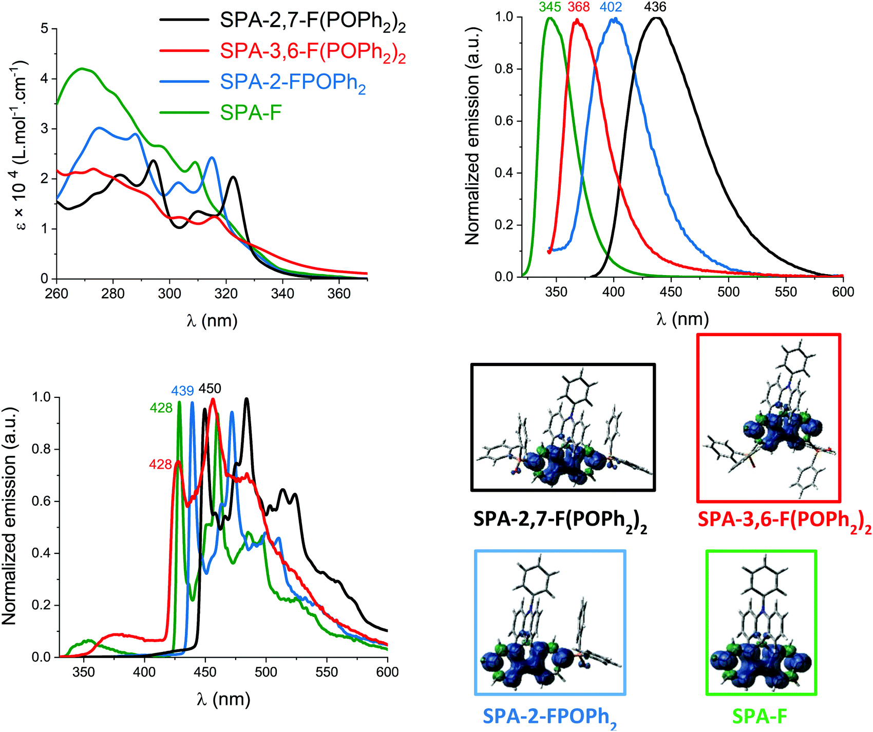 | ||
| Fig. 2 UV-vis absorption spectra in cyclohexane (top-left). Normalized emission spectra at room temperature in cyclohexane, λexc = 310 nm (top-right). Emission spectra at 77 K in 2-MeTHF (λexc = 310 nm) normalized at the phosphorescence maxima (bottom-left). Triplet spin density distribution (TD-DFT, b3lyp/6-311+g(d,p), isovalue 0.002, bottom right) of SPA-2,7-F(POPh2)2, (black lines) SPA-3,6-F(POPh2)2 (red lines), SPA-2-FPOPh2 (blue lines) and SPA-F (green lines). | ||
 | ||
| Fig. 3 Representation of the energy levels and the main molecular orbitals involved in the electronic transitions of SPA-F, SPA-2,7-F(POPh2)2, SPA-3,6-F(POPh2)2 and SPA-2-FPOPh2 obtained by TD-DFT B3LYP and the 6-311+G(d,p) basis set on the geometry of S0, shown with an isovalue of 0.04 [e Bohr−3]1/2 (for clarity purpose, only the main contribution for each transition is shown, details provided in ESI†). | ||
Note that the TD-DFT calculations of the four compounds show that the first excited state corresponds to a forbidden HOMO–LUMO transition, not detectable experimentally, Fig. 3. This is due to the spatial separation of HOMO and LUMO levels (HOMO localized on the acridine core and LUMO on the substituted fluorene core, Fig. 3) leading to a through-space forbidden transition.65 This feature is caused by the insulating spiro bridge (despite a weak coupling exists as shown above in the electrochemical analyses) and indicates that the electronic coupling between the electron-rich unit and the electron-poor units is efficiently restrained, which is a key point in the present design to maintain a high triplet state energy level ET, as exposed below.
Two features can be concluded. First, the red shift observed for SPA-3,6-F(POPh2)2 compared to SPA-F shows that despite a meta linkage is involved in SPA-3,6-F(POPh2)2, electronic coupling exists between the fluorene and the phosphine oxide units. This feature has recently been approached in literature for meta linked spirobifluorene based materials.10,60 Second, it is interesting to note that the effect of one phosphine oxide at C2 is similar in term of absorption wavelength to that of two at C3/C6 (the two molecules have almost identical λmax). This shows how the absorption properties can be tuned by the number and the position of the substituents.
In fluorescence spectroscopy (cyclohexane, Fig. 2-top right), the spectra are unresolved and we note a gradual red shift of their maxima from SPA-F (345 nm), SPA-3,6-F(POPh2)2 (368 nm), SPA-2-FPOPh2 (402 nm), and to SPA-2,7-F(POPh2)2 (436 nm). Thus, adding two phosphine oxides at C3/C6 in SPA-3,6-F(POPh2)2 leads to a significant red shift of ca. 20 nm, showing again the electronic coupling between the fluorene and the phosphine oxides. This red shift is even more pronounced, ca. 60 nm, for SPA-2-FPOPh2 due to the substitution at C2 (para position). The double substitution at C2/C7 in SPA-2,7-F(POPh2)2 leads to an impressive 90 nm shift. Also, from SPA-F to SPA-2,7-F(POPh2)2 the fluorescence band becomes larger and larger. This trend is in accordance with that highlighted in absorption but the red shifts from SPA-F to SPA-2,7-F(POPh2)2 are larger due to a charge transfer character more and more important from SPA-F to SPA-2,7-F(POPh2)2.
Finally, the three investigated compounds are very bad emitters with quantum yields below 0.02 (Table 1). This is in accordance with the spatial separation of HOMO and LUMO (HOMO/LUMO transition presents an oscillator strength of ca. 0, Fig. 3). This characteristic is usually found in host materials for phosphors.65–67
The phosphorescent contributions evaluated thanks to the emission spectra at 77 K in 2-MeTHF are well resolved, very similar in shape but different in terms of wavelengths. The lowest ET in the series is logically found for SPA-2,7-F(POPh2)2, 2.76 eV, which displays a first phosphorescence contribution at 450 nm (Fig. 2, bottom-left). Molecular modelling indicates that the ET of 2,7-(POPh2)2F-SPA is fully governed by the diphenylphosphineoxide-fluorene fragment as visualized by the triplet spin density found on the fluorene core and slightly on the phenyl units of the phosphine oxide (Fig. 2, bottom-right). Removing one phosphine oxide in SPA-2-FPOPh2 increases the ET by 0.06 eV (2.82 eV, λ = 439 nm) and concentrates the triplet spin density on the fluorene core. The highest ET in the series is found for SPA-3,6-F(POPh2)2, which displays a very high ET of 2.90 eV (λ = 428 nm) due to its double meta connection. This value is identical to that of model compound SPA-F (2.90 eV), meaning that the effect of the fluorene substitution is completely cancelled in the triplet state (note that the triplet spin density is exclusively spread out on the fluorene core, Fig. 2, bottom-right). This result is different to that observed for S1 but in accordance with previous reports on the different trend observed between S1 and T1 states.56,60,68 Indeed, it has been previously shown that meta linkages of a fluorene core lead to a red shift of both absorption and fluorescence but do not modify the first phosphorescence contribution. This interesting design strategy seems to be easily adapted to the present fluorene/phosphine oxide systems. For all compounds, the emission from T1 state is confirmed by the very long lifetime measured at 77 K for these four compounds (τ = 3.1, 3.9, 4.7 and 5.6 s for SPA-2,7-F(POPh2)2, SPA-2-FPOPh2, SPA-3,6-F(POPh2)2 and SPA-F respectively, Table 1).
It should finally be stressed out that, at 77 K, a very weak fluorescence contribution is observed for the three compounds SPA-2,7-F(POPh2)2, SPA-3,6-F(POPh2)2 and SPA-F and almost none for SPA-2-FPOPh2. This is a different behaviour than that observed for many other host materials, in which the fluorescence is very intense at 77 K.4,69 This feature is connected to the very low fluorescence quantum yield measured at room temperature for all compounds. Indeed, the intersystem crossing between S1 and T1 is favoured, and leads at 77 K to an intense phosphorescence contribution and a weak fluorescence contribution.70,71 Note that, in the case of SPA-2,7-F(POPh2)2, the S1 and T1 states are the closest in the series (<0.4 eV) and the fluorescence and phosphorescence contributions are overlapped (S1 energies have been evaluated from the onset of the emission spectra at room temperature and T1 energies have been evaluated from the peak maximum at 77 K as often found in literature72). This S1/T1 gap increases by shifting the phosphine oxide units from C2/C7 to C3/C6 (0.7 eV for SPA-3,6-F(POPh2)2) or by removing one phosphine oxide unit (0.6 eV for SPA-2-FPOPh2) or two (0.9 eV for SPA-F). In fact, both S1 and T1 states decrease upon conjugation expansion, with a significantly more important effect on the S1 states compared to T1 states. This is why, in the case of the highly conjugated SPA-2,7-F(POPh2)2, the S1 state decreases close to the T1 state.
The thermal properties have been studied by thermogravimetric analyses (TGA, see ESI†) and differential scanning calorimetry (DSC, Fig. 4). Due to the presence of the rigid spiro bridge and bulky diphenylphosphine oxides, SPA-2,7-F(POPh2)2, SPA-3,6-F(POPh2)2 and SPA-2-FPOPh2 display higher decomposition temperature Td (5% mass loss) than unsubstituted SPA-F (Td = 286 °C). The highest Td is recorded for SPA-2,7-F(POPh2)2 at ca. 474 °C (see ESI†). The positive influence of the diphenylphosphine oxide units on the thermal properties is confirmed by DSC. Thus, during the 2nd heating run (between 20 and 350 °C), the glass transition temperature Tg increases from SPA-F to SPA-2-FPOPh2 when adding one phosphine oxide (90 vs. 118 °C, Fig. 4). The Tg are even much increased when two phosphine oxides are present within the molecular structure, 143 °C for SPA-2,7-F(POPh2)2 and 165 °C for SPA-3,6-F(POPh2)2. One can hence note that the positions C3/C6 provide the material with the highest Tg.
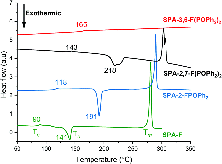 | ||
| Fig. 4 DSC traces (2nd heating) of SPA-2,7-F(POPh2)2 (black line), SPA-3,6-F(POPh2)2 (red line), SPA-2-FPOPh2 (blue line) and SPA-F (green line). | ||
One can also note that both SPA-2,7-F(POPh2)2 and SPA-2-FPOPh2 respectively present a crystallization temperature Tc at ca. 218 and 191 °C (during the 2nd heating cycle), also observed for SPA-F but at a much lower temperature, i.e. 141 °C (Fig. 4). Thus, incorporating one or two diphenylphosphine oxide units in C2/C7 allows to significantly increase the Tc. The substitution at meta positions (C3/C6) of SPA-3,6-F(POPh2)2 leads to a different result as neither Tc nor Tm (melting) transitions are observed during the 2nd heating cycle, of great interest for further OLED applications.
The device architecture simplification, by removing interfacial layers, requires that the host matrix can efficiently act simultaneously as hole and electron charge carrier. In order to allow recombination of opposite charges within the EML, it is moreover necessary to have a good balance between hole and electron carrier mobilities. Otherwise, excitons are created near an electrode, which increases the quenching rate due to non-radiative recombination. In this respect, the charge transport property characterization is mandatory in order to rationalize the structure – device efficiency relationship in these host materials for PhOLED applications. As PhOLEDs are vertical devices, space charge limited current (SCLC) devices appear to be the most appropriate devices to probe the charge carrier mobilities. Indeed, by elaborating hole-only and electron-only devices, one can access the out-of-plane hole and electron mobilities respectively (see ESI† for composition and elaboration details).
The hole/electron mobility (μh/μe) of SPA-2,7-F(POPh2)2, SPA-2-FPOPh2, and SPA-3,6-F(POPh2)2 have been estimated to be 8.2 × 10⁻⁶/2.0 × 10−4 cm2 V−1 s−1, 1.9 × 10⁻⁷/1.3 × 10−5 cm2 V−1 s−1 and 1.4 × 10⁻⁸/3.1 × 10−6 cm2 V−1 s−1, respectively (Fig. 5). One can first interestingly note that the electron mobility is higher than that of hole for the three hosts studied herein. This is a key point as it allows to balance the hole transporting nature of the iridium complexes (FIrpic,73 Ir(ppy)3,74 no data found in literature for Ir(MDQ)2(acac)). It is always awkward to explain trends in mobility values from a series of molecules. However, one can note that SPA-2,7-F(POPh2)2, which is the molecule with the larger conjugation (compared to SPA-3,6-F(POPh2)2), the greatest symmetry (compared to SPA-2-FPOPh2), and the highest electron affinity (i.e. lowest LUMO level), exhibits the highest electron and hole mobilities. With a single phosphine oxide unit, SPA-2-FPOPh2 exhibits both structural asymmetry and lower electron affinity. As a consequence, both mobilities decrease by more than one order of magnitude. Finally, SPA-3,6-F(POPh2)2 has the lowest charge carrier mobilities. This is in good agreement with the amorphous nature of this derivative, as shown by DSC analysis.
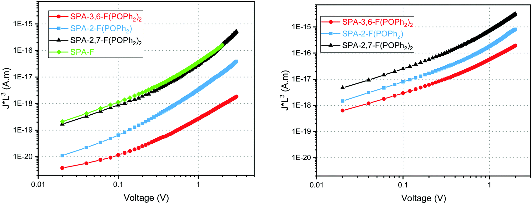 | ||
| Fig. 5 Thickness-scaled current voltage characteristics of SPA-2,7-F(POPh2)2 (black lines), SPA-3,6-F(POPh2)2 (red lines), SPA-2-FPOPh2 (blue lines) and SPA-F (green lines) hole- (left) and electron-only (right) SCLC devices. | ||
In addition, if we consider the mobility balance between electrons and holes (μe/μh) in each molecule, calculated at ca. 24, 68 and 221 for SPA-2,7-F(POPh2)2, SPA-2-FPOPh2, and SPA-3,6-F(POPh2)2, respectively, SPA-2,7-F(POPh2)2 appears clearly as the most suitable candidate to transport charges into a PhOLED device.
The different molecules were finally incorporated as host in red, green and blue SL-PhOLEDs using as emitter either Ir(MDQ)2(acac) for red emission, Ir(ppy)3 for green emission, and FIrpic or FIr6 for blue emission (Tables 2, 3 and Fig. 6, 7). The SL-PhOLED architecture is the following: ITO/PEDOT:PSS (40 nm)/EML (host + guest 10% wt) (100 nm)/LiF (1.2 nm)/Al (100 nm) with ITO/PEDOT:PSS as anode and LiF/Al as cathode.
| Ir(MDQ)2(acac) | Ir(ppy)3 | FIrpic | FIr6 | |
|---|---|---|---|---|
| a In 2-MeTHF, λexc = 310 nm. b Dispersed in the host materials, either in SPA-2,7-F(POPh2)2, SPA-3,6-F(POPh2)2 or SPA-2-FPOPh2. c From first phosphorescence peak. d Onset potential vs. SCE. e In CH2Cl2. f From electrochemical data (onset oxidation or reduction potentials). g ΔEel = |HOMO–LUMO|. | ||||
| λ em [nm] rt/77 K/filmb | 613/597/630 | 511/493/517 | 465/456/471 | 456/449/460 |
| E T [eV] RT/77 K/filmb | 2.02/2.08/1.97 | 2.43/2.51/2.40 | 2.67/2.72/2.63 | 2.72/2.76/2.70 |
| E ox [V] | 0.96, 1.67 | 0.69, 1.74 | 1.28, 1.80 | 1.4 (sh), 1.56 |
| E red [V] | −1.68 (sh) | No distinct wave | −2.04 | −2.40 (sh) |
| HOMOf [eV] | −5.26 | −4.97 | −5.55 | −5.66 |
| LUMOf [eV] | −2.91 | −2.19 | −2.52 | −2.32 |
| ΔEelg [eV] | 2.35 | 2.78 | 3.03 | 3.34 |
| V on (V) | EQE (%) | CE (cd A−1) | PE (lm W−1) | L (cd m−2) | EQE (%) | CE (cd A−1) | PE (lm W−1) | L (cd m−2) | CIE coordinates (x; y) | |
|---|---|---|---|---|---|---|---|---|---|---|
| At 10 mA cm−2 | Max (at J (mA cm−2)) | At 10 mA cm−2 | ||||||||
| Red PhOLEDs (10% Ir(MDQ)2(acac)) | ||||||||||
| SPA-2,7-F(POPh2)2 | 2.8 | 6.0 | 6.2 | 2.0 | 1501 | 8.7 (0.03) | 9.1 (0.03) | 7.0 (0.03) | 6843 (170) | 0.64; 0.36 |
| SPA-3,6-F(POPh2) | 3.6 | 4.4 | 4.4 | 1.3 | 1007 | 5.3 (0.04) | 5.4 (0.04) | 3.0 (0.04) | 2973 (120) | 0.64; 0.36 |
| SPA-2-FPOPh2 | 3.2 | 2.6 | 3.2 | 1.1 | 673 | 4.5 (0.04) | 5.5 (0.04) | 3.5 (0.04) | 151 (220) | 0.63; 0.37 |
| Green PhOLEDs (10% Ir(ppy)3) | ||||||||||
| SPA-2,7-F(POPh2)2 | 2.3 | 11.0 | 37.8 | 18.2 | 9946 | 16.4 (0.04) | 56.3 (0.04) | 53.6 (0.04) | 38970 (180) | 0.31; 0.63 |
| SPA-3,6-F(POPh2)2 | 2.7 | 9.4 | 35.3 | 13.8 | 8099 | 13.9 (0.03) | 52.0 (0.03) | 38.9 (0.03) | 18610 (150) | 0.31; 0.63 |
| SPA-2-FPOPh2 | 2.7 | 7.5 | 25.6 | 13.4 | 6386 | 10.4 (0.02) | 35.6 (0.02) | 32.9 (0.02) | 15490 (90) | 0.31; 0.63 |
| Sky Blue PhOLEDs (10% FIrpic) | ||||||||||
| SPA-2,7-F(POPh2)2 | 2.5 | 12.5 | 27.3 | 14.5 | 5276 | 18.0 (0.04) | 39.0 (0.04) | 38.4 (0.04) | 8030 (80) | 0.15; 0.37 |
| SPA-3,6-F(POPh2)2 | 3.5 | 6.5 | 12.3 | 4.0 | 2013 | 6.5 (6.8) | 12.3 (6.8) | 4.2 (6.8) | 2540 (50) | 0.16; 0.38 |
| SPA-2-FPOPh2 | 2.8 | 8.0 | 16.2 | 6.3 | 3896 | 8.6 (0.24) | 17.3 (0.24) | 10.5 (0.24) | 9578 (100) | 0.15; 0.37 |
| Blue PhOLEDs (10% FIr6) | ||||||||||
| SPA-2,7-F(POPh2)2 | 2.8 | 5.4 | 8.6 | 4.3 | 2220 | 6.5 (27.7) | 10.4 (27.7) | 4.5 (27.7) | 2687 (50) | 0.16; 0.33 |
| SPA-3,6-F(POPh2)2 | 4.6 | 5.1 | 11.5 | 4.2 | 604 | 6.5 (1.2) | 14.7 (1.2) | 6.8 (1.2) | 661 (40) | 0.16; 0.32 |
| SPA-2-FPOPh2 | 2.9 | 9.0 | 15.9 | 7.9 | 3518 | 9.1 (14.6) | 16.2 (14.6) | 7.7 (14.6) | 4952 (60) | 0.15; 0.30 |
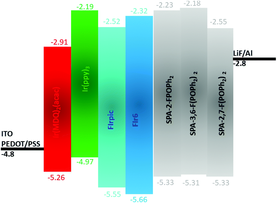 | ||
| Fig. 6 Schematic energy diagrams of the different components used in the EML of the present SL-PhOLEDs. | ||
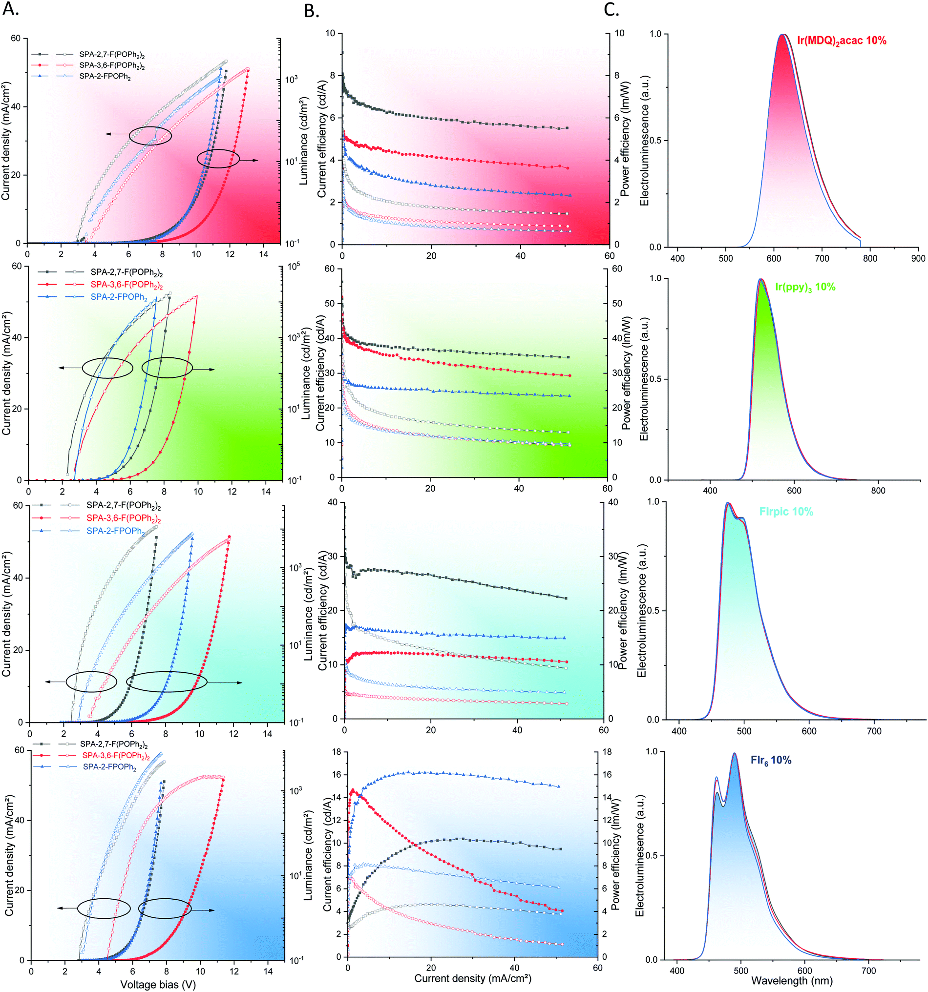 | ||
| Fig. 7 SL-PhOLEDs characteristics using as a host either SPA-2,7-F(POPh2)2 (black lines), SPA-3,6-F(POPh2)2 (red lines) or SPA-2-FPOPh2 (blue lines). (A) Current density (mA cm−2) and luminance (cd m−2) as a function of the bias voltage; (B) current efficiency (cd A−1, filled symbols) and power efficiency (lm W−1, empty symbol) as a function of the current density (mA cm−2) and (C) normalized EL spectra. | ||
First, the four iridium complexes have been studied in strictly identical conditions in order to precisely determine their electronic properties and particularly their HOMO and LUMO energy levels and ET (Table 2). It is important to mention that many data can be found in literature for these phosphors but recorded in different experimental conditions (FIrpic,73 Ir(ppy)3,75,76 FIr6,77 Ir(MDQ)2(acac)78,79). This heterogeneity renders the comparison with host materials and between them difficult. In the case of SL-PhOLED, studying both host materials and phosphors in identical experimental conditions appear particularly important.
Thus, in 2-MeTHF at room temperature, the ET of Ir(MDQ)2(acac), Ir(ppy)3, FIrpic and FIr6 have been evaluated at 2.02, 2.43, 2.67 and 2.72 eV respectively from the maximum of first emission peak. At 77 K in a frozen 2-MeTHF matrix (in the same conditions than those used to measure the ET of the hosts), there is a blue shift of the emission spectra (Table 2) due to the decrease of molecular motions and the ET are therefore slightly increased at 2.08, 2.51, 2.72 and 2.76 eV. In thin films, dispersed into the host materials studied herein (corresponding to the EML of the devices studied below), the spectra are red shifted and the ET are measured at 1.97, 2.40, 2.63 and 2.70 eV (note that the spectra of each complex are independent of the matrix used, see ESI†). In these conditions, the thin-film phosphorescent spectra appear to be identical to the electroluminescent (EL) spectra presented below, showing the similitude of the optical processes involved.
The HOMO/LUMO of Ir(MDQ)2(acac), (Ir(ppy)3), FIrpic and FIr6 have also been evaluated by electrochemical analyses in solution (in CH2Cl2 + Bu4NPF6 0.2 M, see CV in ESI†) at −5.26/−2.91, −4.97/−2.19, −5.55/−2.52, −5.66/−2.32 eV. These data are particularly interesting to interpret the device performance presented below.
First, the phosphor Ir(MDQ)2(acac) (HOMO = −5.26/LUMO = −2.91 eV, ET = 1.97 eV dispersed in the present hosts, Table 2) has been used as red-emitting dopant in SL-PhOLEDs. The best performance has been obtained with SPA-2,7-F(POPh2)2 as host reaching a maximum EQE of 8.7%. The best device reaches a maximum luminance L of 6843 cd m−2 at 170 mA cm−2 showing a good stability at high current density. The two other hosts SPA-3,6-F(POPh2)2 and SPA-2-FPOPh2, studied in strictly identical experimental conditions display lower performance with low EQE of ca. 5%, Table 3. This can be related to the strong difference observed in terms of charge carrier mobilities as exposed above. Indeed, the hole and electron mobilities of SPA-2,7-F(POPh2)2 are not only significantly higher than those of both SPA-3,6-F(POPh2)2 and SPA-2-FPOPh2 but also more balanced. When the charge transport is not balanced, the recombination zone is located close to the metal electrodes, thereby causing exciton quenching by the electrodes and reducing the device efficiency. This feature is surely at the origin of the higher device performance observed for red SL-PhOLEDs using SPA-2,7-F(POPh2)2 as host. This will be confirmed with the other dopants presented below. On the other hand, the very low LUMO level of Ir(MDQ)2(acac), −2.91 eV, is also involved in the moderate performance observed for the three hosts, the host possessing the lowest LUMO, i.e.SPA-2,7-F(POPh2)2/LUMO = −2.55 eV leading to the highest performance. The three devices also display a different threshold voltage (Von): 2.8 V for SPA-2,7-F(POPh2)2, 3.2 V for SPA-2-FPOPh2 and 3.6 V for SPA-3,6-F(POPh2)2, translating (i) the different charge injections within the devices. This is in accordance with the different energy gaps observed for the three compounds (2.78 eV for SPA-2,7-F(POPh2)2, 3.10 eV for SPA-2-FPOPh2 and 3.13 V for SPA-3,6-F(POPh2)2) the lowest gap leading to the lowest Von and herein to the highest EQE. The different Von can also be related to the different μe/μh ratio of the hosts, the highest μe/μh leading to the highest Von in the case of SPA-3,6-F(POPh2)2, and the lowest μe/μh leading to the lowest Von in the case of SPA-2,7-F(POPh2)2.
The green SL-PhOLEDs have been then studied in a similar way using the classical green emitter Ir(ppy)3 (HOMO = −4.97 eV, LUMO = −2.19 eV, ET = 2.40 eV dispersed in the present hosts, Table 2). Usually, green-emitting SL-PhOLEDs display the highest performances (compare to blue and red) as green phosphors are usually the easiest to host in a PhOLED. The difference in terms of performances between the three hosts is less marked than for the red phosphor. Indeed, if the highest performance has been again reached with SPA-2,7-F(POPh2)2, the two other host materials also display interesting performances. The lowest efficiency is recorded for SPA-2-FPOPh2, which displays a maximal EQE of 10.4%, and corresponding CE of 35.6 cd A−1 and PE of 32.9 lm W−1 at 0.02 mA cm−2 (Table 3). The performances are increased with SPA-3,6-F(POPh2)2 as a high maximal EQE of 13.9% and corresponding CE of 52.0 cd A−1 and PE of 38.9 lm W−1 (at 0.03 mA cm−2) are recorded. The best performance is finally obtained with SPA-2,7-F(POPh2)2 as host with a maximal EQE of 16.4%, and corresponding CE of 56.3 cd A−1 and PE of 53.6 lm W−1 at 0.04 mA cm−2 (Table 3). A maximum luminance of 38970 cd m−2 at 180 mA cm−2 is reached, translating a high performance and a good stability at high current density. In accordance with the data exposed above for the red phosphor, SPA-2,7-F(POPh2)2 displays the lowest Von in the series, 2.3 V due to its most contracted gap and lowest μe/μh in the series. During the writing of this manuscript, Isobe and coworkers have reported green SL-PhOLEDs with a higher EQE, overpassing 20%.34
Blue phosphors are the most difficult to host and blue-emitting PhOLEDs remain the weakest link of the technology.5,18,42,68,80–82 In this work, two blue phosphors have been used: the classical sky blue emitter FIrpic (HOMO = −5.55 eV/LUMO = −2.52 eV, ET = 2.63 eV dispersed in the present hosts, Table 2) and the barely studied blue emitter FIr6 (HOMO = −5.66 eV/LUMO = −2.32 eV, ET = 2.70 eV dispersed in the present hosts, Table 2). Usually, when both the HOMO/LUMO gap and ET of the phosphor increase, the PhOLED efficiency dramatically drops. In a multi-layer PhOLED, this can be compensate by the transporting and blocking layers but in single-layer device, this is far more difficult. To the best of our knowledge, only a few examples of blue SL-PhOLEDs (using a single host) is reported and all of them use the sky blue emitter FIrpic.24,35–37,83 Indeed, the other blue dopants found in OLEDs literature, for example FCNIrpic (HOMO = −5.87 eV/LUMO = −2.65 eV, see ESI†)84,85 and FIr640,53,54 (used in this study) are exclusively found as emitter in multi-layer PhOLEDs and not in SL-PhOLEDs using a single host (note that one example is reported but using a different host/co-host strategy47).
Thus, with FIrpic as sky blue emitter, SPA-3,6-F(POPh2)2 displays this time the lowest performance with a low EQE of 6.5% and a high Von of 3.5 V in accordance with a bad charges recombination and injection. The EQE is interestingly increased to 8.6% with SPA-2-FPOPh2 and the Von is decreased to 2.8 V signing a better charges injection, transport and recombination than in SPA-3,6-F(POPh2)2. It is nevertheless difficult to assign why SPA-2-FPOPh2 displays a higher performance than SPA-3,6-F(POPh2)2 as the opposite was observed for the two other phosphors presented above. The case of SPA-2,7-F(POPh2)2 is very different as it displays with FIrpic excellent performances. Indeed, a very high EQE of 18.0% (CE = 39.0 cd A−1 and PE = 38.4 lm W−1) was measured at 0.04 mA cm−2 (Table 3) and a maximum luminance of 8030 cd m−2 at 80 mA cm−2 was reached. We assign the very high efficiency of SPA-2,7-F(POPh2)2 to the combination of many parameters. The high and well balanced mobilities of charge carriers are surely involved in this high performance as it is a key point when designing a host material for SL-PhOLED. It is also important to state that the LUMO levels of FIrpic and SPA-2,7-F(POPh2)2 (Fig. 6 and Tables 2, 3) are very close and can also be involved in the present high performance. For these sky blue SL-PhOLEDs, the trend in term of Von is similar to those exposed above for the other phosphors. Note that the Von of SPA-2,7-F(POPh2)2 based device is very low, 2.5 V, signing an efficient charges injection in the EML and well-balanced hole and electron mobilities. In a similar device configuration and as far as we are aware, only one host previously reported in literature displays a higher performance with FIrpic as emitter (EQE of 20.3%).36 This molecule, reported by Liu and coworkers, incorporates an electron poor bis(diphenylphosphine oxide)-fluorene unit and a pendant diphenyl amine,86 possessing therefore a similar molecular structure than that described herein. The higher performance obtained with this host compared to that of SPA-2,7-F(POPh2)2 can be assigned to a better hole and electron mobilities balance. One can nevertheless note that our FIrpic-based devices display lower Von (2.5 vs. 3 V), translating the electrochemical gap difference between the two molecules (2.79 vs. 2.86 eV).
Finally, in order to go deeper in the versatility of the present hosts and to reach devices emitting at shorter wavelength, blue phosphor FIr6 (HOMO = −5.66 eV/LUMO = −2.32 eV, ET = 2.70 eV dispersed in the present hosts) was successfully used as emitter in identical SL-PhOLEDs. We were first surprised to note that SPA-2-FPOPh2 displays this time the highest efficiency in the series with an interesting maximal EQE of 9.1%. This value is even higher than that recorded with FIrpic. Note that the LUMO level of SPA-2-FPOPh2 is very close to that of FIr6 (−2.23 vs. −2.32 eV) and can be the explanation for this performance (the same observation, i.e. very close LUMO levels between host and guest, was also done with SPA-2,7-F(POPh2)2 and FIrpic above). Surprisingly, the EQE of SPA-2,7-F(POPh2)2 is very low, 6.5%, whereas this host was the most efficient for all the other guests. We can tentatively assigned this feature to its relatively low ET, 2.76 eV, which is very close to that of FIr6 and back energy transfer may occur decreasing the PhOLED performance. Finally, as observed for FIrpic, the efficiency of SPA-3,6-F(POPh2)2 is very low. The EQE reaches indeed 6.5% at a low current density but strongly decreases as the current density increases, showing the very bad performance of this host with this guest emitter. Compared to the only example of SL-PhOLED using FIr6 found in literature (which is nevertheless different as a host/co-host is used in the EML),47SPA-2-FPOPh2 displays significantly improved performance (9.1 vs. 6.5%), clearly highlighting the efficiency of the chemical design strategy used herein. To conclude, these data show the real difficulty to design versatile hosts, which can be efficiently used with RGB phosphors. As the thickness of the EML has not been optimized for this last phosphor, it is obvious that the encouraging performance observed with SPA-2-FPOPh2 will be easily overpassed in the future.
It should be finally mentioned that all the devices exhibited identical red, green or blue emission arising exclusively from their corresponding iridium complex (and are therefore independent of the matrix used), showing an efficient energy transfer cascade (see electroluminescent spectra for all the device in Fig. 7). This is confirmed by the study of the emission spectra of the EML (host + guest 10% without electrodes), which are identical to the corresponding electroluminescent spectra (see ESI†). The CIE chromatic coordinates of the electroluminescent spectra are reported in Table 3. It is particularly important to note that FIrpic based devices display CIE coordinates of (0.15, 0.37) whereas those of FIr6 are shifted to (0.15, 0.30) confirming a more blue emission for the latter.
Conclusion
In this work, we have investigated different phenylacridine/diphenylphosphineoxide associations within a single host for RGB SL-PhOLEDs. The synthetic strategy developed is short, versatile, efficient, and uses cheap starting materials. For the future of the OLED technology, reducing the synthetic chemistry steps is highly required to reduce its environmental footprint. This work shows how the number and the position of the diphenylphosphine oxide units attached to the spirophenylacridine-fluorene backbone significantly impact the physical and electronic properties.The three molecules investigated herein have been incorporated as host material in simplified single-layer PhOLEDs with four different iridium complexes emitting in the red, green and blue regions. With these conditions, we have shown how each parameter of the host (HOMO/LUMO energy levels, ET, charge carriers mobility) influences the emission efficiency of the guest phosphor within the device and how a subtle combination of these three parameters is required. In addition, this work also reports the first examples of SL-PhOLEDs using the blue emitter FIr6. With this phosphor, the mono-substituted SPA-2-FPOPh2 displays the best performance in the series with a maximal EQE of 9.1% and a low Von below 3 V. These first results appear very promising and deserve device optimizations in the future. As simplifying the device structure can be a central feature in the future of OLEDs, designing efficient and stable semi-conductors for this purpose is an important step. However, more researches are undoubtedly needed not only in term of molecular design but also in term of device engineering. Recently, it has been shown that specific treatment of ITO (using chlorinated ITO followed by UV ozone treatment as anode) is an efficient technique to improve the performance of SL-PHOLEDs.32 Combining the best device architectures with the best host materials may result to very high efficiency SL-PhOLEDs.
Conflicts of interest
There are no conflicts to declare.Acknowledgements
The authors would like to thank the ANR (SPIROQUEST, no. 19-CE05-0024) for financial support of this project and the Région Bretagne (DIADEM project) for PhD grant (FL). We would like to thank Dr Franck Camerel for his help in DSC measurements and the CRMPO (Rennes) for mass analysis. This work was granted access to the HPC resources of CINES under the allocation 2020-A0080805032 made by GENCI. The authors thank Dr J. F. Bergamini (Rennes) for the TOC material.References
- M. A. Baldo, D. F. O'Brien, Y. You, A. Shoustikov, S. Sibley, M. E. Thompson and S. R. Forrest, Nature, 1998, 395, 151–154 CrossRef CAS.
- Y. Tao, C. Yang and J. Qin, Chem. Soc. Rev., 2011, 40, 2943–2970 RSC.
- K. S. Yook and J. Y. Lee, Adv. Mater., 2014, 26, 4218–4233 CrossRef CAS.
- C. Poriel and J. Rault-Berthelot, J. Mater. Chem. C, 2017, 5, 3869–3897 RSC.
- Q. Wang, F. Lucas, C. Quinton, Y.-K. Qu, J. Rault-Berthelot, O. Jeannin, S.-Y. Yang, F.-C. Kong, S. Kumar, L.-S. Liao, C. Poriel and Z.-Q. Jiang, Chem. Sci., 2020, 11, 4887–4894 RSC.
- A. Maheshwaran, V. G. Sree, H.-Y. Park, H. Kim, S. H. Han, J. Y. Lee and S.-H. Jin, Adv. Funct. Mater., 2018, 28, 1802945 CrossRef.
- W. Li, J. Li, D. Liu and Q. Jin, ACS Appl. Mater. Interfaces, 2016, 8, 22382–22391 CrossRef CAS.
- J.-J. Huang, Y.-H. Hung, P.-L. Ting, Y.-N. Tsai, H.-J. Gao, T.-L. Chiu, J.-H. Lee, C.-L. Chen, P.-T. Chou and M.-K. Leung, Org. Lett., 2016, 18, 672–675 CrossRef CAS.
- L. Ding, S.-C. Dong, Z.-Q. Jiang, H. Chen and L. S. Liao, Adv. Funct. Mater., 2015, 25, 645–650 CrossRef CAS.
- L.-S. Cui, Y.-M. Xie, Y.-K. Wang, C. Zhong, Y.-L. Deng, X.-Y. Liu, Z.-Q. Jiang and L.-S. Liao, Adv. Mater., 2015, 27, 4213–4217 CrossRef CAS.
- K. Udagawa, H. Sasabe, C. Cai and J. Kido, Adv. Mater., 2014, 26, 5062–5066 CrossRef CAS.
- Y. Im, S. Y. Byun, J. H. Kim, D. R. Lee, C. S. Oh, K. S. Yook and J. Y. Lee, Adv. Funct. Mater., 2017, 27, 1603007 CrossRef.
- C. W. Lee and J. Y. Lee, Adv. Mater., 2013, 25, 5450–5454 CrossRef CAS.
- X. Tang, X.-Y. Liu, Y. Yuan, Y.-J. Wang, H.-C. Li, Z.-Q. Jiang and L.-S. Liao, ACS Appl. Mater. Interfaces, 2018, 10, 29840–29847 CrossRef CAS.
- M. Kim and J. Y. Lee, ACS Appl. Mater. Interfaces, 2014, 6, 14874–14880 CrossRef CAS.
- X.-Y. Liu, X. Tang, Y. Zhao, D. Zhao, J. Fan and L.-S. Liao, ACS Appl. Mater. Interfaces, 2018, 10, 1925–1932 CrossRef CAS.
- K.-H. Kim, S. Lee, C.-K. Moon, S.-Y. Kim, Y.-S. Park, J.-H. Lee, J. Woo Lee, J. Huh, Y. You and J.-J. Kim, Nat. Commun., 2014, 5, 4769 CrossRef CAS.
- W.-C. Chen, Y. Yuan, Z.-L. Zhu, Z.-Q. Jiang, S.-J. Su, L.-S. Liao and C.-S. Lee, Chem. Sci., 2018, 9, 4062–4070 RSC.
- C. Poriel and J. Rault-Berthelot, Adv. Funct. Mater., 2020, 30, 1910040 CrossRef CAS.
- W.-Y. Hung, T.-C. Tsai, S.-Y. Ku, L.-C. Chi and K.-T. Wong, Phys. Chem. Chem. Phys., 2008, 10, 5822–5825 RSC.
- X. Qiao, Y. Tao, Q. Wang, D. Ma, C. Yang, L. Wang, J. Qin and F. Wang, J. Appl. Phys., 2010, 108, 034508 CrossRef.
- J. Ye, Z. Chen, K. Wang, F. An, Y. Yuan, W. Chen, Q. Yang, X. Zhang and C.-S. Lee, Chem. – Eur. J., 2014, 20, 13762–13769 CrossRef CAS.
- C. Zang, X. Peng, H. Wang, Z. Yu, L. Zhang, W. Xie and H. Zhao, Org. Electron., 2017, 50, 106–114 CrossRef CAS.
- Z. Liu, M. G. Helander, Z. Wang and Z. Lu, Org. Electron., 2009, 10, 1146–1151 CrossRef CAS.
- Q. Jiang, Y. Xu, T. Yu, X. Qiu, R. Zhao, D. Zhao, N. Zheng, D. Hu, Z. Xie and Y. Ma, New J. Chem., 2019, 43, 6721–6727 RSC.
- C.-H. Chen, W.-S. Huang, M.-Y. Lai, W.-C. Tsao, J. T. Lin, Y.-H. Wu, T.-H. Ke, L.-Y. Chen and C.-C. Wu, Adv. Funct. Mater., 2009, 19, 2661–2670 CrossRef CAS.
- M.-Y. Lai, C.-H. Chen, W.-S. Huang, J. T. Lin, T.-H. Ke, L.-Y. Chen, M.-H. Tsai and C.-C. Wu, Angew. Chem., Int. Ed., 2008, 47, 581–585 CrossRef CAS.
- J. P. J. Markham, S.-C. Lo, S. W. Magennis, P. L. Burn and I. D. W. Samuel, Appl. Phys. Lett., 2002, 80, 2645–2647 CrossRef CAS.
- W.-Y. Hung, T.-C. Wang, H.-C. Chiu, H.-F. Chen and K.-T. Wong, Phys. Chem. Chem. Phys., 2010, 12, 10685–10687 RSC.
- B. Huang, W. Jiang, J. Tang, X. Ban, R. Zhu, H. Xu, W. Yang and Y. Sun, Dyes Pigm., 2014, 101, 9–14 CrossRef CAS.
- S. Thiery, D. Tondelier, B. Geffroy, E. Jacques, M. Robin, R. Métivier, O. Jeannin, J. Rault-Berthelot and C. Poriel, Org. Lett., 2015, 17, 4682–4685 CrossRef CAS.
- Z. Wu, Z. Yang, K. Xue, C. Fei, F. Wang, M. Yan, H. Zhang, D. Ma and W. Huang, RSC Adv., 2018, 8, 11255–11261 RSC.
- F. Lucas, O. A. Ibraikulov, C. Quinton, L. Sicard, T. Heiser, D. Tondelier, B. Geffroy, N. Leclerc, J. Rault-Berthelot and C. Poriel, Adv. Opt. Mater., 2020, 8, 1901225 CrossRef CAS.
- A. Yoshii, Y. Onaka, K. Ikemoto, T. Izumi, S. Sato, H. Kita, H. Taka and H. Isobe, Chem. – Asian J., 2020, 15, 2181–2186 CrossRef CAS.
- H.-H. Chang, W.-S. Tsai, C.-P. Chang, N.-P. Chen, K.-T. Wong, W.-Y. Hung and S.-W. Chen, Org. Electron., 2011, 12, 2025–2032 CrossRef CAS.
- F.-M. Hsu, L.-J. Chien, K.-T. Chen, Y.-Z. Li and S.-W. Liu, Org. Electron., 2014, 15, 3327–3332 CrossRef CAS.
- Y. Yin, X. Wen, J. Yu, L. Zhang and W. Xie, IEEE Photonics Technol. Lett., 2013, 25, 1041–1135 Search PubMed.
- Y. Yin, X. Piao, Y. Wang, J. Liu, K. Xu and W. Xie, Appl. Phys. Lett., 2012, 101, 063306 CrossRef.
- K. S. Yook and J. Y. Lee, Adv. Mater., 2012, 24, 3169–3190 CrossRef CAS.
- K. Gao, K. Liu, X.-L. Li, X. Cai, D. Chen, Z. Xu, Z. He, B. Li, Z. Qiao, D. Chen, Y. Cao and S.-J. Su, J. Mater. Chem. C, 2017, 5, 10406–10416 RSC.
- C.-C. Lai, M.-J. Huang, H.-H. Chou, C.-Y. Liao, P. Rajamalli and C.-H. Cheng, Adv. Funct. Mater., 2015, 25, 5548–5556 CrossRef CAS.
- X.-D. Zhu, Y.-L. Zhang, Y. Yuan, Q. Zheng, Y.-J. Yu, Y. Li, Z.-Q. Jiang and L.-S. Liao, J. Mater. Chem. C, 2019, 7, 6714–6720 RSC.
- Y. Zhao, C. Wu, P. Qiu, X. Li, Q. Wang, J. Chen and D. Ma, ACS Appl. Mater. Interfaces, 2016, 8, 2635–2643 CrossRef CAS.
- W. Song, L. Shi, L. Gao, P. Hu, H. Mu, Z. Xia, J. Huang and J. Su, ACS Appl. Mater. Interfaces, 2018, 10, 5714–5722 CrossRef CAS.
- Y. Miao, K. Wang, L. Gao, B. Zhao, H. Wang, F. Zhu, B. Xu and D. Ma, J. Mater. Chem. C, 2018, 6, 8122–8134 RSC.
- W. Jiang, L. Duan, D. Zhang, G. Dong, L. Wang and Y. Qiu, J. Mater. Chem., 2010, 20, 6131–6137 RSC.
- C. Fan, Y. Li, C. Yang, H. Wu, J. Qin and Y. Cao, Chem. Mater., 2012, 24, 4581–4587 CrossRef CAS.
- K. H. Yeoh, N. A. Talik, T. J. Whitcher, C. Y. B. Ng and K. L. Woon, J. Phys. D: Appl. Phys., 2014, 47, 205103 CrossRef.
- S. E. Jang and J. Y. Lee, J. Lumin., 2011, 131, 2788–2791 CrossRef CAS.
- N. C. Erickson and R. J. Holmes, Appl. Phys. Lett., 2010, 97, 083308 CrossRef.
- J. Y. Xue, T. Izumi, A. Yoshii, K. Ikemoto, T. Koretsune, R. Akashi, R. Arita, H. Taka, H. Kita, S. Sato and H. Isobe, Chem. Sci., 2016, 7, 896–904 RSC.
- K. Ikemoto, A. Yoshii, T. Izumi, H. Taka, H. Kita, J. Y. Xue, R. Kobayashi, S. Sato and H. Isobe, J. Org. Chem., 2016, 81, 662–666 CrossRef CAS.
- C. Wu, B. Wang, Y. Wang, J. Hu, J. Jiang, D. Ma and Q. Wang, J. Mater. Chem. C, 2019, 7, 558–566 RSC.
- H.-H. Chou and C.-H. Cheng, Adv. Mater., 2010, 22, 2468–2471 CrossRef CAS.
- C. Poriel, L. Sicard and J. Rault-Berthelot, Chem. Commun., 2019, 55, 14238–14254 RSC.
- C. Poriel and J. Rault-Berthelot, Acc. Chem. Res., 2018, 51, 1818–1830 CrossRef CAS.
- J.-D. Peltier, B. Heinrich, B. Donnio, E. Jacques, J. Rault-Berthelot and C. Poriel, ACS Appl. Mater. Interfaces, 2017, 9, 8219–8232 CrossRef CAS.
- J.-D. Peltier, B. Heinrich, B. Donnio, O. Jeannin, J. Rault-Berthelot and C. Poriel, Chem. – Eur. J., 2017, 23, 17290–17303 CrossRef CAS.
- S. Bebiche, P. Cisneros-Perez, T. Mohammed-Brahim, M. Harnois, J. Rault-Berthelot, C. Poriel and E. Jacques, Mater. Chem. Front., 2018, 2, 1631–1641 RSC.
- L. Sicard, C. Quinton, J.-D. Peltier, D. Tondelier, B. Geffroy, U. Biapo, R. Métivier, O. Jeannin, J. Rault-Berthelot and C. Poriel, Chem. – Eur. J., 2017, 23, 7719–7723 CrossRef CAS.
- S. Thiery, C. Declairieux, D. Tondelier, G. Seo, B. Geffroy, O. Jeannin, R. Métivier, J. Rault-Berthelot and C. Poriel, Tetrahedron, 2014, 70, 6337–6351 CrossRef CAS.
- C. Quinton, L. Sicard, O. Jeannin, N. Vanthuyne and C. Poriel, Adv. Funct. Mater., 2018, 28, 180340 CrossRef.
- M. Romain, D. Tondelier, B. Geffroy, O. Jeannin, E. Jacques, J. Rault-Berthelot and C. Poriel, Chem. – Eur. J., 2015, 21, 9426–9439 CrossRef CAS.
- I. Bulut, P. Chavez, S. Fall, S. Mery, B. Heinrich, J. Rault-Berthelot, C. Poriel, P. Leveque and N. Leclerc, RSC Adv., 2016, 6, 25952–25959 RSC.
- M. Romain, D. Tondelier, O. Jeannin, B. Geffroy, J. Rault-Berthelot and C. Poriel, J. Mater. Chem. C, 2015, 3, 97010–97014 Search PubMed.
- M. Romain, M. Chevrier, S. Bebiche, T. Mohammed-Brahim, J. Rault-Berthelot, E. Jacques and C. Poriel, J. Mater. Chem. C, 2015, 3, 5742–5753 RSC.
- M. Romain, D. Tondelier, B. Geffroy, A. Shirinskaya, O. Jeannin, J. Rault-Berthelot and C. Poriel, Chem. Commun., 2015, 51, 1313–1315 RSC.
- L. J. Sicard, H.-C. Li, Q. Wang, X.-Y. Liu, O. Jeannin, J. Rault-Berthelot, L.-S. Liao, Z.-Q. Jiang and C. Poriel, Angew. Chem., Int. Ed., 2019, 58, 3848–3853 CrossRef CAS.
- C. Quinton, S. Thiery, O. Jeannin, D. Tondelier, B. Geffroy, E. Jacques, J. Rault-Berthelot and C. Poriel, ACS Appl. Mater. Interfaces, 2017, 9, 6194–6206 CrossRef CAS.
- C. Poriel, J. Rault-Berthelot, S. Thiery, C. Quinton, O. Jeannin, U. Biapo, B. Geffroy and D. Tondelier, Chem. – Eur. J., 2016, 22, 17930–17935 CrossRef CAS.
- S. Thiery, D. Tondelier, C. Declairieux, B. Geffroy, O. Jeannin, R. Métivier, J. Rault-Berthelot and C. Poriel, J. Phys. Chem. C, 2015, 119, 5790–5805 CrossRef CAS.
- D. H. Ahn, S. W. Kim, H. Lee, I. J. Ko, D. Karthik, J. Y. Lee and J. H. Kwon, Nat. Photonics, 2019, 13, 540–546 CrossRef CAS.
- E. Baranoff and B. F. E. Curchod, Dalton Trans., 2015, 44, 8318–8329 RSC.
- W.-H. Choi, G. Tan, W.-Y. Sit, C.-L. Ho, C. Y.-H. Chan, W. Xu, W.-Y. Wong and S.-K. So, Org. Electron., 2015, 24, 7–11 CrossRef CAS.
- J.-H. Seo, N.-S. Han, H.-S. Shim, J.-H. Kwon and J.-K. Song, Bull. Korean Chem. Soc., 2011, 32, 1415–1418 CrossRef CAS.
- G. Tan, S. Chen, N. Sun, Y. Li, D. Fortin, W.-Y. Wong, H.-S. Kwok, D. Ma, H. Wu, L. Wang and P. D. Harvey, J. Mater. Chem. C, 2013, 1, 808–821 RSC.
- R. J. Holmes, B. W. D’Andrade, S. R. Forrest, X. Ren, J. Li and M. E. Thompson, Appl. Phys. Lett., 2003, 83, 3818–3820 CrossRef CAS.
- Y. L. Chang, Z. B. Wang, M. G. Helander, J. Qiu, D. P. Puzzo and Z. H. Lu, Org. Electron., 2012, 13, 925–931 CrossRef CAS.
- J. P. Duan, P. P. Sun and C. H. Cheng, Adv. Mater., 2003, 15, 224–228 CrossRef CAS.
- R. Mertens, The OLED Handbook: A Guide to OLED Technology, Industry & Market, 2019th edn, 2019 Search PubMed.
- K. Klimes, Z.-Q. Zhu and J. Li, Adv. Funct. Mater., 2019, 29, 1903068 CrossRef.
- S. Hu, J. Zeng, X. Zhu, J. Guo, S. Chen, Z. Zhao and B. Z. Tang, ACS Appl. Mater. Interfaces, 2019, 11, 27134–27144 CrossRef CAS.
- Y. Liu, L.-S. Cui, M.-F. Xu, X.-B. Shi, D.-Y. Zhou, Z.-K. Wang, Z.-Q. Jiang and L. S. Liao, J. Mater. Chem. C, 2014, 2, 2488–2495 RSC.
- S. O. Jeon, S. E. Jang, H. S. Son and J. Y. Lee, Adv. Mater., 2011, 23, 1436–1441 CrossRef CAS.
- S. O. Jeon, K. S. Yook, C. W. Joo and J. Y. Lee, Adv. Funct. Mater., 2009, 19, 3644–3649 CrossRef CAS.
- F.-M. Hsu, C.-H. Chien, C.-F. Shu, C.-H. Lai, C.-C. Hsieh, K.-W. Wang and P.-T. Chou, Adv. Funct. Mater., 2009, 19, 2834–2843 CrossRef CAS.
Footnote |
| † Electronic supplementary information (ESI) available: Details on the materials synthesis, their structural, thermal and electrochemical properties, theoretical calculations, device data are provided. 2D NMR studies and copies of NMR spectra are also included. See DOI: 10.1039/d0tc04650g |
| This journal is © The Royal Society of Chemistry 2020 |