
An artificial photosynthesis system comprising a covalent triazine framework as an electron relay facilitator for photochemical carbon dioxide reduction†
Siquan
Zhang‡
a,
Shengyao
Wang‡
 b,
Liping
Guo
a,
Hao
Chen
b,
Bien
Tan
a and
Shangbin
Jin
*a
b,
Liping
Guo
a,
Hao
Chen
b,
Bien
Tan
a and
Shangbin
Jin
*a
aKey Laboratory of Material Chemistry for Energy Conversion and Storage, Ministry of Education, School of Chemistry and Chemical Engineering, Huazhong University of Science and Technology, Luoyu Road No. 1037, 430074, Wuhan, China. E-mail: jinsb@hust.edu.cn
bCollege of Science, Huazhong Agricultural University, Wuhan 430070, P. R. China
First published on 11th November 2019
Abstract
Natural photosystem II, which utilizes multiple photosensitizers, is essentially an organic–inorganic hybrid system, and comprises electron transfer relay processes. The relay processes can facilitate charge transfer and reduce charge recombination. Thus it can significantly improve photocatalytic performance. Such a strategy has rarely been studied for CO2 reduction in conjugated porous polymers. Here we report a new organic–inorganic hybrid material, which constitutes an electron transfer relay photocatalytic system for CO2 reduction using a porous framework as a relay facilitator. The system was fabricated by decorating a new porphyrin-based covalent triazine framework (Por-CTF) with α-Fe2O3 nanoparticles using an in situ strategy, which was then coupled with a Ru complex photosensitizer. Owing to the formation of an electron transfer relay system, the ternary system exhibits a sharp enhancement in photocatalytic activity towards CO2 reduction to CO as compared with the binary system. The best performance given by the electron transfer relay system (α-Fe2O3@Por-CTF-10×/Ru(bpy)3Cl2) produces a catalytic CO evolution rate of 8.0 μmol h−1 with 93% CO selectivity, which is obviously superior to that of the binary system. The highest apparent quantum efficiency was also evaluated as 1.43% at 450 nm. This work provides a prototype model system for the design of an artificial photocatalytic system for photochemical CO2 reduction.
Introduction
Carbon dioxide (CO2) which is largely emitted from fossil fuels has resulted in global warming and an adverse influence on the environment.1,2 A number of research efforts have been made to decrease the CO2 level in the atmosphere, with the target of achieving a carbon-neutral society. Photochemical reduction of CO2 is a promising route to decrease CO2 by transforming it into value-added chemical fuels, such as carbon monoxide (CO), methane (CH4) and so on.3 For example, using iron porphyrin as photocatalyst can convert CO2 to CH4.4,5 A highly porous metal–organic framework (Co-ZIF-9) can reduce CO2 to CO in a similar photocatalytic system that has the benefits of high CO2 adsorption ability and a porous framework.6,7Conjugated porous organic polymers (cPOPs),8 including covalent organic frameworks (COFs),9–18 covalent triazine frameworks (CTFs)19–42 and conjugated microporous polymers (CMPs),43–49 are receiving enormous attention in photocatalysis because of their unique porous and semiconducting properties. These materials have been widely studied for CO2 adsorption, but the application for photochemical CO2 reduction remains in its infancy. Their high surface areas and tuneable pore sizes would give advantages in the photocatalytic process for CO2 adsorption and mass transfer. Baeg et al. first demonstrated a film CTF constructed using perylene diimide to transform CO2 into formic acid by photocatalysis.50 Cao et al. recently further reported a Re-modified CTF that is a capable photocatalyst for CO2 reduction to CO.51 Wang et al. reported that functional CMPs show high efficacy for photochemical CO2 reduction to CO assisted by Co(bpy)3Cl2 and triethanolamine (TEOA).52 Liu et al. reported a series of pyrene-based CMPs that can convert CO2 to CO using an ionic liquid.53 Zhu et al. found that an azine-linked COF could catalyse CO2 to methanol.54 Zou et al. very recently reported a COF functionalized with metal bipyridyl complex that could reduce CO2 to CO.55 These works demonstrated that the band gaps and energy levels of cPOPs can be easily tuned owing to their structural flexibility and variable synthetic methods. As above, cPOPs have enormous potential for photochemical CO2 reduction, but developing new strategies to increase performance remains necessary.
In natural photosystem II, multiple photosensitizers (e.g., chlorophyll and quinone) are employed to work as light-harvesting and charge transfer/separation systems, which are then coupled with a Mn4OxCa nanocluster reaction centre to form a photochemical machine.56 Thus, this natural photosystem is essentially a kind of organic–inorganic hybrid system forming an electron transfer relay system that facilitates charge transfer and reduces charge combination. To the best of our knowledge, development of such an electron transfer relay system for photocatalytic CO2 reduction in conjugated porous polymers is unprecedented.57–59
In this work, we constructed a novel organic–inorganic hybrid artificial electron transfer relay photocatalytic system for photocatalytic CO2 reduction, in which Ru(bpy)3Cl2 works as photosensitizer, CTF as an electron relay facilitator, and α-Fe2O3 as an inorganic co-catalyst. First, a binary hybrid, α-Fe2O3@Por-CTF, was fabricated by in situ growth of α-Fe2O3 nanoparticles into a new porphyrin CTF (Por-CTF), allowing small α-Fe2O3 crystallites to spread in the Por-CTF. The porphyrin structures are well-known and play a pivotal role in the natural photosynthesis system.5,56 Thus, it would be effective to construct a porphyrin-based conjugated porous organic polymer working as a light-harvesting or electron antenna, which promises to lead to an efficient photocatalysis system. Here, α-Fe2O3, which has not previously been studied for photochemical CO2 reduction, works as a co-catalyst. It is a low-cost and abundant semiconductor for photocatalysis, but is limited by low conduction band and rapid charge recombination of photogenerated charges for photocatalytic CO2 reduction.60–62 In the binary hybrid, the Por-CTF with large surface area porous structure would be of benefit for collecting both electrons and CO2 during photocatalysis. The small α-Fe2O3 nanoparticles can be strongly coupled with the support owing to the nitrogen-rich structure of Por-CTF, and thus would provide a large interface for charge transfer and separation between both semiconductors as compared with the direct mixing method. In addition, by tuning the ratio of the components, the size of the α-Fe2O3 crystallites would be modulated and thus the performance may be effectively optimized. Ru(bpy)3Cl2 was added as photosensitizer, to form an electron transfer relay system with cascade band energy positions. By comparison with control experiments, the electron transfer relay system showed a greatly enhanced activity as compared with the binary hybrid system (i.e. Por-CTF/Ru(bpy)3Cl2, α-Fe2O3/Ru(bpy)3Cl2, and α-Fe2O3@Por-CTF), which indicated that this was an effective strategy to achieve enhanced photocatalytic activity. This work provides a new guideline for the design of an artificial photocatalytic system for CO2 reduction via mimicking a natural photosystem.63–66
Results and discussion
Synthesis and characterization of materials
As depicted in Scheme 1, the electron transfer relay system comprised Ru(bpy)3Cl2, Por-CTF and α-Fe2O3. Of these, Por-CTF was prepared via polycondensation of the amidine with a porphyrin aldehyde monomer, which formed a porous network structure (Fig. S1, ESI†).35 Then, the designed artificial photosystem was fabricated by the following procedures (Fig. 1b). Initially, a ferric chloride aqueous solution was prepared to provide a source of FeOOH. Afterwards, Por-CTF was added to the above solution, so that the FeOOH precursor gradually grew on the Por-CTF to form a hybrid, FeOOH@Por-CTF. Then, the FeOOH@Por-CTF was filtered out and annealed in an oven at a fixed temperature for 24 hours to form the α-Fe2O3@Por-CTF hybrid system. By controlling the amount of the precursor, we prepared a series of photocatalysts which we named α-Fe2O3@Por-CTF-X (X indicates the molar ratio of the structural units of Por-CTF to the α-Fe2O3 precursor). The ratio of the two components was varied from 5×, to 10×, to 15×, which generated three hybrid materials, namely α-Fe2O3@Por-CTF-5×, α-Fe2O3@Por-CTF-10× and α-Fe2O3@Por-CTF-15×.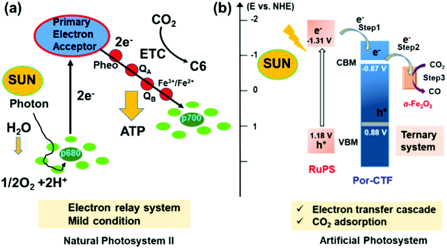 | ||
| Scheme 1 (a) A schematic diagram of natural photosystem II. ATP, adenosine triphosphate; ETC, electron transport chain. (b) A schematic diagram of the electron transfer process for the photocatalytic reduction of CO2. | ||
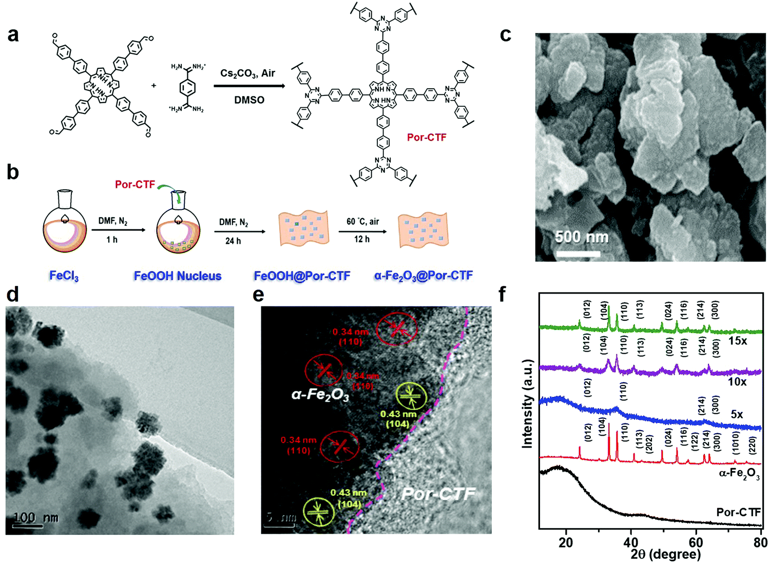 | ||
| Fig. 1 (a) Synthesis route of Por-CTF. (b) Fabrication of the α-Fe2O3@Por-CTF hybrid photocatalyst based on Por-CTF. (c) FE-SEM image of Por-CTF. (d) TEM image of α-Fe2O3@Por-CTF-10×. (e) HR-TEM image of α-Fe2O3@Por-CTF-10× and lattice fringes of α-Fe2O3. (f) Powder X-ray diffraction patterns of Por-CTF (black), α-Fe2O3 (red), α-Fe2O3@Por-CTF-5× (blue), α-Fe2O3@Por-CTF-10× (purple), and α-Fe2O3@Por-CTF-15× (green). | ||
As shown in Fig. S2 (ESI†), in the Fourier-transform infrared (FT-IR) spectra the triazine structures are characterized by typical vibration stretches at 1350 cm−1 and 1500 cm−1 attributed to the triazine unit in Por-CTF and α-Fe2O3@Por-CTF. Moreover, Fig. S3a (ESI†) shows that the solid-state 13C nuclear magnetic resonance (NMR) spectrum of Por-CTF exhibits two typical broad peaks at 160–180 ppm and 120–150 ppm, which can be assigned to the carbon of porphyrin, consistent with the reported porphyrin polymer.67 In addition, the peak at 170 ppm can be assigned to the carbon in the triazine structure. Thermogravimetric analysis (TGA) showed that Por-CTF and α-Fe2O3@Por-CTF-10× are stable up to 400 °C (Fig. S3b, ESI†). From the TGA curves, the content of α-Fe2O3 in α-Fe2O3@Por-CTF-10× is estimated to be approximately 23.9%. The iron content of the prepared samples was further measured by inductive coupled plasma optical emission spectrometry (ICP-OES) (Table S1, ESI†). The results showed that the iron contents of the α-Fe2O3@Por-CTF-5×, α-Fe2O3@Por-CTF-10×, and α-Fe2O3@Por-CTF-15× samples are 8.98, 18.08 and 20.29 wt%, respectively. Accordingly, the α-Fe2O3 content in α-Fe2O3@Por-CTF-10× was calculated to be 25.83 wt%, which is very close to the value estimated from TGA.
The high-resolution C 1s X-ray photoelectron spectrum (XPS) of Por-CTF, shown in Fig. S4a (ESI†), can be deconvoluted into three major peaks with binding energies of 284.9, 286.2 and 288.7 eV. The peak located at 284.9 eV can be assigned to carbon atoms in the aryl units present in the skeleton (C![[double bond, length as m-dash]](https://www.rsc.org/images/entities/char_e001.gif) C). The peaks at 286.2 and 288.7 eV are attributed to the carbon atoms present in the triazine structure and porphyrin structure with CN–C and N–CN bonding, respectively. The N 1s XPS can be deconvoluted into peaks at 398.9 eV and 400.1 eV, corresponding to pyridinic N (from triazine structure) and pyrrolic N (from porphyrin structure) in the Por-CTF (Fig. S4b, ESI†). The ratio of the areas of the pyridinic N (from triazine structure) and pyrrolic N peaks is close to 1
C). The peaks at 286.2 and 288.7 eV are attributed to the carbon atoms present in the triazine structure and porphyrin structure with CN–C and N–CN bonding, respectively. The N 1s XPS can be deconvoluted into peaks at 398.9 eV and 400.1 eV, corresponding to pyridinic N (from triazine structure) and pyrrolic N (from porphyrin structure) in the Por-CTF (Fig. S4b, ESI†). The ratio of the areas of the pyridinic N (from triazine structure) and pyrrolic N peaks is close to 1![[thin space (1/6-em)]](https://www.rsc.org/images/entities/char_2009.gif) :1, which is in line with the theoretical value.
:1, which is in line with the theoretical value.
Field emission scanning electron microscope (FE-SEM) images (Fig. 1c) and transmission electron microscope (TEM) images (Fig. S5a and b, ESI†) show that Por-CTF has plate-like particulate morphology. As shown in Fig. S5d–f (ESI†), the high-angle annular dark field scanning transmission electron microscope (HAADF-STEM) images of Por-CTF show the mapping of the carbon (cyan) and nitrogen (purple), indicating the elements are evenly distributed in the framework. The TEM and high-resolution TEM (HR-TEM) images (Fig. 1d and e, respectively) show that the α-Fe2O3 crystallites are well-supported on the Por-CTF. The powder X-ray diffraction (PXRD) pattern of Por-CTF (Fig. 1f) exhibits a broad peak at 19°, which can be assigned to π–π interaction of the conjugated structure. With an increasing amount of the iron precursor, the peaks arising from α-Fe2O3 in the PXRD patterns of α-Fe2O3@Por-CTF become clearer and their intensity increases. The PXRD pattern matches JCPDS no. 01-080-2377, and can be unambiguously assigned to α-Fe2O3 (Fig. S6, ESI†).
The amount of precursor has a considerable effect on the sizes of α-Fe2O3 nanoparticles in the resulting hybrid system. When the ratio is increased from 5×, to 10×, to 15×, the average sizes of α-Fe2O3 particles increase from 77 nm, to 101 nm, to 180 nm (Fig. S7, ESI†). In the HR-TEM image shown in Fig. 1e, the lattice fringes of α-Fe2O3 in α-Fe2O3@Por-CTF-10× can be observed, which indicates that the α-Fe2O3 crystallites mainly expose their crystalline planes on the Por-CTF. In addition, HAADF-STEM images of the hybrid system (Fig. S8, ESI†) clearly show the α-Fe2O3 nanoparticles are surely supported on Por-CTF. The corresponding elements are shown in energy dispersive X-ray spectroscopy (EDX) for α-Fe2O3@Por-CTF-10× (Fig. S8 and S9, ESI†).
Fig. 2a shows the low-resolution XPS of α-Fe2O3, Por-CTF and α-Fe2O3@Por-CTF-10×, which demonstrate the materials contain Fe 2p, N 1s, O 1s, and C 1s. Fe 2p and N 1s of α-Fe2O3 and α-Fe2O3@Por-CTF-10× (Fig. S10, ESI†) are consistent with each other. In Fig. 2b, the peaks with binding energy at 710.9 eV and 724.5 eV indicate the presence of 2p3/2 and 2p1/3 belonging to Fe 2p, which clearly indicates that the crystalline nanoparticle is α-Fe2O3. The XPS results in Table S2 (ESI†) show that the content of Fe on the surface of Por-CTF increases when more precursor is added. Fig. S11 (ESI†) shows the N 1s profile of Por-CTF and different α-Fe2O3@Por-CTF-X samples. The high-resolution C 1s and O 1s profiles of α-Fe2O3@Por-CTF-X also match Por-CTF and α-Fe2O3 and thus we can deduce that Por-CTF has successfully been decorated with α-Fe2O3. Specifically, the Fe 2p, O 1s and N 1s profiles of α-Fe2O3@Por-CTF-10× respectively match Por-CTF and α-Fe2O3 very well, as shown in Fig. 2b–d. This confirms the organic–inorganic hybrid material did not change the chemical structure of independent semiconductors.
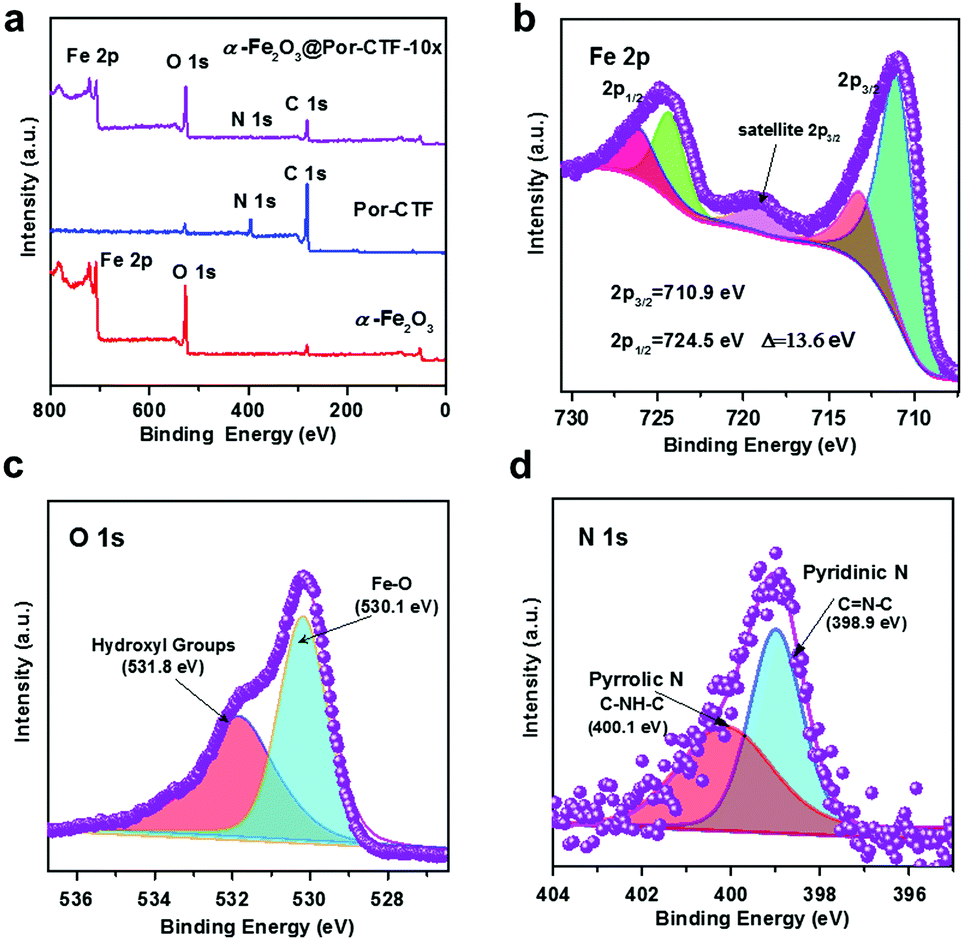 | ||
| Fig. 2 (a) Low-resolution XPS. (b) High-resolution Fe 2p XPS of α-Fe2O3@Por-CTF-10×. (c) High-resolution O 1s XPS of α-Fe2O3@Por-CTF-10×. (d) High-resolution N 1s XPS of α-Fe2O3@Por-CTF-10×. | ||
Photocatalytic performance
The ultraviolet-visible (UV-vis) spectra exhibit a wide visible light absorption range, as shown in Fig. S12 (ESI†). The band gaps of α-Fe2O3, Por-CTF and α-Fe2O3@Por-CTF-10× are calculated to be 2.01 eV, 1.62 eV and 1.75 eV, respectively. From Mott–Schottky plots of Por-CTF and α-Fe2O3, as shown in Fig. S12a and b (ESI†), the conduction bands (CBs) of Por-CTF and α-Fe2O3 are estimated as −0.87 V (vs. NHE) and −0.25 V (vs. NHE), respectively. Moreover, the valence bands (VBs) of Por-CTF and α-Fe2O3 are deduced to be 0.88 V (vs. NHE) and 2.08 V (vs. NHE), respectively. The CB of Por-CTF (−0.87 V vs. NHE) is more negative than the reduction potential of carbon dioxide to carbon monoxide (CO2/CO −0.53 V vs. NHE), thus the photochemical reduction of CO2 is energetically feasible.In the photocatalytic system, Ru(bpy)3Cl2, which has been widely used as photosensitizer for photocatalytic CO2 reduction, was coupled with α-Fe2O3@Por-CTF-10× and formed an electron relay photocatalytic system. The photocatalytic reduction performances obtained are depicted in Fig. S13 and S14 (ESI†). We first explored the impact of the amount of the photocatalyst on the catalytic activity. As shown in Table S3 (ESI†), when the amount of photocatalyst is increased, the evolution rate of CO becomes higher, but the selectivity decreases. A ratio of 20 mg α-Fe2O3@Por-CTF-10× to 5 mg Ru(bpy)3Cl2 was found to be optimal in the photocatalytic reduction, considering both activity and selectivity. α-Fe2O3@Por-CTF-10×/Ru(bpy)3Cl2 exhibits the best performance, with a photocatalytic CO evolution rate of 8.0 μmol h−1 and selectivity of 93% for CO (Table 1, entry 1). Recycling experiments showed that α-Fe2O3@Por-CTF-10× is stable, with good recyclability for three cycles (Fig. 3b). As shown in Fig. S15 (ESI†), the hybrid catalyst is stable and shows no obvious structural change after photocatalysis as evidenced by TEM images and FT-IR spectrum.
| Entry | Catalyst | Gas | λ/nm | CO/μmol h−1 | H2/μmol h−1 | Selectivity/% |
|---|---|---|---|---|---|---|
|
a Physical mixture.
b Without TEOA and Ru(bpy)3Cl2. Typical experimental conditions: 20 mg of photocatalyst, 5 mg (7 μmol) of Ru(bpy)3Cl2·6H2O, 5 mL of DMF/TEOA (4:1 by volume) at 293 K.
|
||||||
| 1 | α-Fe2O3@Por-CTF-10×/Ru(bpy)3Cl2 | CO2 | >420 | 8.0 | 0.6 | 93 |
| 2 | α-Fe2O3@Por-CTF-10×/Ru(bpy)3Cl2 | N2 | >420 | — | 1.3 | 0 |
| 3 | α-Fe2O3@Por-CTF-10×/Ru(bpy)3Cl2 | CO2 | Dark | — | — | — |
| 4 | α-Fe2O3/Ru(bpy)3Cl2 | CO2 | >420 | 0.6 | 2.2 | 21 |
| 5 | Por-CTF/Ru(bpy)3Cl2 | CO2 | >420 | 0.2 | 0.1 | 67 |
| 6a | α-Fe2O3/Por-CTF/Ru(bpy)3Cl2 | CO2 | >420 | 1.5 | 1.2 | 56 |
| 7b | α-Fe2O3@Por-CTF-10× | CO2 | >420 | 0.72 | — | 100 |
| 8 | Ru(bpy)3Cl2 | CO2 | >420 | — | 0.4 | 0 |
| 9 | Por-CTF | CO2 | >420 | 0.21 | — | 100 |
| 10 | α-Fe2O3 | CO2 | >420 | — | — | — |
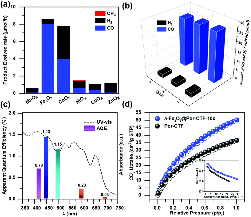 | ||
| Fig. 3 (a) Photocatalytic performance of CO evolution with MnOx@Por-CTF-10×, α-Fe2O3@Por-CTF-10×, CoOx@Por-CTF-10×, NiOx@Por-CTF-10×, CuOx@Por-CTF-10× and ZnOx@Por-CTF-10× (20 mg) in 5 mL of DMF/TEOA (4/1 with 7 μmol of Ru(bpy)3Cl2). (b) Recyclability and stability experiments. (c) Wavelength dependence of the AQE of α-Fe2O3@Por-CTF-10×. (d) CO2 adsorption and desorption curves at 273 K (inset: isosteric heat of adsorption, Qst). | ||
As shown in the Fig. 3a, Por-CTF can be loaded with various metal oxides, such as MnOx, CoOx, NiOx, CuOx, ZnOx and α-Fe2O3, but it was found that α-Fe2O3 was the optimal co-catalyst, resulting in the highest evolution rate and selectivity. Other metal oxide@Por-CTF-10×/Ru(bpy)3Cl2 showed very low efficiency and selectivity for CO reduction under the same conditions. Among the metal oxides, only CoOx@Por-CTF-10×/Ru(bpy)3Cl2 showed a comparable photocatalytic activity to α-Fe2O3@Por-CTF-10×/Ru(bpy)3Cl2, but its selectivity was only 51%. Fig. 3c shows the electron transfer relay system has a good apparent quantum efficiency (AQE), the highest AQE of α-Fe2O3@Por-CTF-10× being 1.43% at 450 nm. The performance is comparable to that of many photocatalytic systems, as summarized in Tables S4 and S5 (ESI†).7,68,69
To demonstrate the effectiveness and clarify the role of each component in the electron transfer relay processes, a series of control experiments were conducted and the results are presented in Fig. S16–S18 (ESI†). The detailed catalytic results are summarized in Table 1. Por-CTF alone exhibits a low CO evolution rate of only 0.21 μmol h−1, while α-Fe2O3 alone is completely inactive because of its low CBM. Ru(bpy)3Cl2 alone also does not show CO2 reduction activity. Furthermore, each of the binary systems (i.e. Por-CTF/Ru(bpy)3Cl2, α-Fe2O3/Ru(bpy)3Cl2, and α-Fe2O3@Por-CTF-10×) was studied: α-Fe2O3@Por-CTF-10× showed a low efficiency of 0.72 μmol h−1 for CO evolution, Por-CTF/Ru(bpy)3Cl2 produced 0.2 μmol h−1, and α-Fe2O3/Ru(bpy)3Cl2 gave 0.6 μmol h−1. Moreover, to compare ternary systems, the physical mixture of α-Fe2O3 nanoparticles and Por-CTF (α-Fe2O3/Por-CTF) in the presence of Ru(bpy)3Cl2 photosensitizer was also studied, which only evolved CO at 1.5 μmol h−1 (Table 1, entry 6).
Apparently, the photochemical CO evolution amount of α-Fe2O3@Por-CTF-10×/Ru(bpy)3Cl2 is much higher than those of the binary systems and the physical mixture. The selectivity of the ternary system is also much higher those of the binary ones. In particular, as shown in Table 1, entry 6, the physical mixture (α-Fe2O3/Por-CTF/Ru(bpy)3Cl2) shows a much higher photocatalytic activity than α-Fe2O3/Ru(bpy)3Cl2 and Por-CTF/Ru(bpy)3Cl2, which indicates that the introduction of Por-CTF as an electron transfer relay facilitator is effective in the ternary system. The photocatalytic performance of the hybrid system (α-Fe2O3@Por-CTF-10×/Ru(bpy)3Cl2) is much higher than that of the physical mixture (α-Fe2O3/Por-CTF/Ru(bpy)3Cl2), indicating the design of the hybrid of α-Fe2O3 in the Por-CTF-10× matrix is unique and beneficial for photocatalytic performance.
When the photochemical reaction was conducted under nitrogen atmosphere instead of CO2, there was no CO detected, indicating that CO is the product arising from CO2 reduction (Table 1, entry 2). GC-MS analysis (Fig. S19, ESI†) showed that the major product 13CO originated from 13CO2 photoreduction, which proved the CO was derived from CO2. To test whether there is any other reaction product, which remains in solution, the 1H-NMR spectrum of the solution was measured before and after the photocatalytic test. As shown in Fig. S20 (ESI†), the spectra did not show any difference, suggesting there are not any obvious products in the solution under our photocatalytic conditions.
Discussion on the electron transfer relay photocatalytic system
As adsorption is crucial for photocatalysis, the porous structure and CO2 adsorption properties of the samples were studied. Nitrogen adsorption analysis (Fig. S21a, ESI†) shows that the Brunauer–Emmett–Teller (BET) specific surface area of Por-CTF is 442.5 m2 g−1 and that of α-Fe2O3@Por-CTF-10× is 453.3 m2 g−1. The pore size analysis in Fig. S21b (ESI†) shows the Por-CTF is a hierarchical porous triazine framework. Por-CTF and α-Fe2O3@Por-CTF-10× exhibit a two-step hysteresis loop in the nitrogen sorption curves, which indicates that mesoporous structures are also present in the porous structures. The ratio of micropores in α-Fe2O3@Por-CTF-10× is higher than that of Por-CTF. The pore width of α-Fe2O3@Por-CTF-10× is also slightly decreased compared with Por-CTF.We then measured the CO2 adsorption of α-Fe2O3@Por-CTF-10×. As shown in Fig. 3d, both α-Fe2O3@Por-CTF-10× and Por-CTF have high CO2 adsorption abilities at 273 K and 1 bar. The α-Fe2O3@Por-CTF-10× has a CO2 adsorption ability of 50 cm3 g−1 (9.82 wt%), which is much higher than that of Por-CTF (35 cm3 g−1, 6.88 wt%), at 273 K and 1 bar. The results indicate the CO2 adsorption ability is enhanced after formation of the hybrid system, which is good for CO2 photoreduction. Interestingly, α-Fe2O3@Por-CTF-10× shows slightly higher isosteric heats of adsorption (Qst) than Por-CTF (inset in Fig. 3d), which could be attributed to the interaction between the α-Fe2O3 and absorbed CO2 molecules. The enhancement of the CO2 adsorption after loading α-Fe2O3 could be explained by the increased BET surface area and higher ratio of micropores after deposition of α-Fe2O3 nanoparticles, which decrease the size of the larger pores.
As presented in Fig. S22a (ESI†), α-Fe2O3@Por-CTF-10× has a much lower fluorescence emission intensity than bare Por-CTF, suggesting the recombination of the photogenerated carriers is suppressed by formation of the binary hybrid photosystem. As shown in Fig. S22b (ESI†), the fluorescence lifetime of α-Fe2O3@Por-CTF-10× (τ = 0.86 ns) also becomes shorter compared with Por-CTF (τ = 3.2 ns). This is evidence that photoinduced electron transfer takes place between the two components. Electrochemical impedance spectroscopy and the photocurrent response also suggested the better charge transfer and transportation ability of the hybrid material. As shown in Fig. S22 and S23 (ESI†), the resistance of α-Fe2O3@Por-CTF-10× is lower than that of Por-CTF (Fig. S22c, ESI†) and the photocurrent of α-Fe2O3@Por-CTF-10× is stronger than for Por-CTF, α-Fe2O3 and other samples (Fig. S22d and S23b, ESI†). Furthermore, spin-trapping electron spin resonance (ESR) spectra were examined. As shown in Fig. 4c and d, the formation of both ˙OH and ˙O2− radicals under visible light can be observed in α-Fe2O3@PCTF-10×, which indicates the hybrid system is effectively formed. Furthermore, the ESR signals of the ˙OH and ˙O2− radicals in α-Fe2O3@PCTF-10× are stronger than those in α-Fe2O3 and PCTF, respectively. As shown in Fig. S24 and S25 (ESI†), there are no radical peaks in the absence of light irradiation, which means that light is required for the generation of intermediates like ˙OH and ˙O2− for CO2 reduction. These results suggest that the hybrid of α-Fe2O3@Por-CTF-10× forms an effective electron transfer system, which can facilitate charge separation and generate more charge carriers for photoredox reactions.
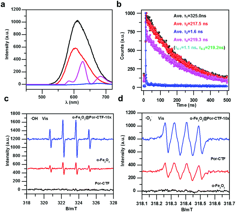 | ||
| Fig. 4 (a) Steady-state photoluminescence spectra of Ru(bpy)3Cl2 (black), Por-CTF/Ru(bpy)3Cl2 (pink), α-Fe2O3@Por-CTF-10×/Ru(bpy)3Cl2 (blue), and α-Fe2O3/Ru(bpy)3Cl2 (red), in 5 mL of DMF/TEOA (4:1 by volume). (b) Time-resolved photoluminescence spectra of Ru(bpy)3Cl2 (black), Por-CTF/Ru(bpy)3Cl2 (pink), α-Fe2O3@Por-CTF-10×/Ru(bpy)3Cl2 (blue), and α-Fe2O3/Ru(bpy)3Cl2 (red), dispersed in 5 mL of DMF/TEOA (4:1 by volume) at 293 K. DMPO spin-trapping ESR spectra recorded for ˙OH (c) and ˙O2− (d) under visible light for α-Fe2O3, Por-CTF, and α-Fe2O3@Por-CTF-10× in 10 minutes. | ||
Next, time-resolved photoluminescence spectra were studied to reveal the charge dynamic behaviour in the electron transfer relay system. As shown in Fig. 4a, the fluorescence of Ru(bpy)3Cl2 in the electron transfer relay system (α-Fe2O3@Por-CTF-10×/Ru(bpy)3Cl2) is significantly quenched as compared with Por-CTF/Ru(bpy)3Cl2, α-Fe2O3/Ru(bpy)3Cl2, and Ru(bpy)3Cl2. Furthermore, the fluorescence lifetime of α-Fe2O3@Por-CTF-10×/Ru(bpy)3Cl2 is also greatly decreased as compared with these samples. As shown in Fig. 4b, the fluorescence lifetime of Ru(bpy)3Cl2 is about 347.7 ns, which is in line with the literature value (≈325.0 ns).70 In contrast, the fluorescence lifetime of α-Fe2O3@Por-CTF-10×/Ru(bpy)3Cl2 is very much less, at τ3 = 1.6 ns. Its fluorescence lifetime is also shorter than those of α-Fe2O3/Ru(bpy)3Cl2 (τ3 = 217.5 ns) and Por-CTF/Ru(bpy)3Cl2 (τ4 = 219.3 ns, τ4–1 = 1.1 ns). These results indicate that the ternary hybrid system significantly suppresses the charge recombination process and facilitates electron transfer. In particular, the sharply decreased lifetime (1.6 ns versus 325.0 ns) strongly evidences the efficient photoinduced electron transfer processes, and accounts for the improved photocatalytic performance.
In order to understand in depth the possible reduction process on the catalyst surface, in situ FT-IR spectra of α-Fe2O3@Por-CTF-10× were examined.71,72 As shown in Fig. S26a–S29a (ESI†), the strong absorption peaks at 1341, and 1570 cm−1 are respectively assignable to νs(CO3), νas(CO3) and ν(CO) of one bidentate carbonate.73 The absorption peaks at 1224, 1401, 1490, 1600 and 1636 cm−1 are assignable to bicarbonates, and the weak absorption at 1704 cm−1 is assignable to carboxylate.70 These results suggest that the activation of CO2 molecules can occur on the surface of α-Fe2O3@Por-CTF-10×. They also show light is necessary for the appearance of these intermediates. Bicarbonates (HCO3*) and carboxylate (COOH*) are intermediates in the photochemical reduction of CO2 to CO. COOH* on the surface of α-Fe2O3@Por-CTF-10× can be reduced to CO* by a proton–electron transfer reduction process.74 Before irradiation, there is no intermediate detected by in situ FT-IR spectroscopy. As shown in Fig. S26b and c (ESI†), the absorption bands (2100–2500 cm−1, 3620 cm−1 and 3726 cm−1) that are assignable to absorptions of gas-phase CO2 decreased after irradiation. The peaks at 2849, 2922, and 2952 cm−1 (Fig. S26, ESI†) indicate abundant hydroxyl groups exist on the catalyst surface, which may play an important role in the adsorption of carbon dioxide. As control tests, the in situ FT-IR spectra of α-Fe2O3 and Por-CTF were also measured. The results showed that α-Fe2O3 can adsorb CO2 and form the bicarbonate (HCO3*) intermediate, but the carboxylate (HCOO*) – which is the key intermediate for the CO evolution – is not observed. This suggests that α-Fe2O3 alone is not an effective photocatalyst (Fig. S27, ESI†). In contrast, both HCO3* and HCOO* are observed in Por-CTF (Fig. S28, ESI†), which indicates that Por-CTF alone is a viable photocatalyst for CO2 reduction to CO. As compared with each other, the intensity of HCO3* in α-Fe2O3 (the strong chemical adsorption of CO2 on the surface) is much higher than that in Por-CTF. This means that α-Fe2O3 is more capable of adsorbing and activating CO2 on the surface. This could be a partial reason for the higher CO2 adsorption after loading α-Fe2O3 nanoparticles in the Por-CTF matrix.
We measured the transient absorption spectra (TAS) of α-Fe2O3@Por-CTF-10×/Ru(bpy)3Cl2. On irradiation by a 395 nm laser, we observed ground-state bleaching at 460 nm and a new peak at 525 nm, which indicates the formation of a triplet excited state deriving from Ru(bpy)3Cl2 (α-Fe2O3@Por-CTF-10×/Ru(bpy)3Cl2, Fig. 5a and b). Transient absorption spectra show that a new peak at 550–600 nm emerges. Calculation of the decay profile showed that α-Fe2O3@Por-CTF-10×/Ru(bpy)3Cl2* decays with a lifetime (τ) of only 0.3764 ps.
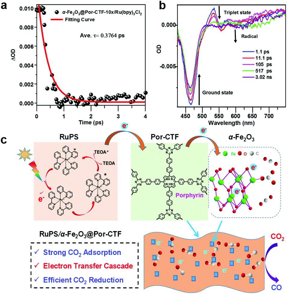 | ||
| Fig. 5 (a) Femtosecond time-resolved transient absorption decay kinetics of α-Fe2O3@Por-CTF-10×/Ru(bpy)3Cl2 and (b) time-resolved transient absorption spectra of α-Fe2O3@Por-CTF-10×/Ru(bpy)3Cl2. (c) Proposed mechanism for the photochemical reaction comprising an electron transfer relay process with Por-CTF as the relay facilitator for carbon dioxide reduction in a ternary hybrid system. | ||
According to the above studies, a photocatalytic mechanism is proposed to describe the photochemical processes, as shown in Fig. 5c. When the photocatalysis system is irradiated with visible light, the photosensitizer ([Ru(bpy)3]2+) is excited to [Ru(bpy)3]2+*, which is then quenched by TEOA, forming the reduced state [Ru(bpy)3]+.8 Afterwards, the energized electrons from [Ru(bpy)3]+ are injected from the photosensitizer to Por-CTF, followed by migration from Por-CTF to the surface of α-Fe2O3 nanoparticles. Finally, the energized electrons meet with the adsorbed CO2 on α-Fe2O3 and the reduction reactions take place. Obviously, this process is composed of multiple electron transfers, forming an electron transfer relay system, which could be analogous to natural photosystem II. Thus, the ternary system can help photocatalysis better than the binary system, because it can effectively suppress the backward electron transfer and make the forward electron transfer take place more efficiently.75–80
Conclusions
In summary, we report an example of a ternary organic–inorganic hybrid as an electron transfer relay system for photochemical CO2 reduction. The hybrid system was prepared via the in situ growth of α-Fe2O3 crystallites on Por-CTF; it exhibits high CO2 adsorption ability and supplies a large interface and short charge transfer distance. It forms an electron transfer relay ternary system after the addition of the Ru(bpy)3Cl2 complex as a photosensitizer and using Por-CTF as an electron transfer relay facilitator, which mimics a natural photosynthesis system. The greatly enhanced photocatalytic performance, with a high CO evolution rate and quantum yield compared with the binary systems, is due to the presence of an electron transfer relay system that can reduce photocurrent carrier recombination and promote the separation efficiency of photogenerated charges. The present study constitutes a new paradigm to mimic a natural photosystem for the design of hybrid photocatalysts based on conjugated porous organic polymers (cPOPs) for CO2 reduction as well as other photochemical applications.Conflicts of interest
There are no conflicts to declare.Acknowledgements
S. Jin would like to acknowledge funding from the National Natural Science Foundation of China (grant no. 21875078, 21604028). B. Tan and S. Jin would like to acknowledge the International S&T Cooperation Program of China (grant no. 2016YFE0124400), and the Program for HUST Interdisciplinary Innovation Team (grant no. 2016JCTD104). The Analysis and Testing Center of Huazhong University of Science and Technology is also greatly acknowledged for their helpful assistance with material characterization.Notes and references
- J. D. Shakun, P. U. Clark, F. He, S. A. Marcott, A. C. Mix, Z. Y. Liu, B. Otto-Bliesner, A. Schmittner and E. Bard, Nature, 2012, 484, 49–54 CrossRef CAS.
- S. Solomon, G. K. Plattner, R. Knutti and P. Friedlingstein, Proc. Natl. Acad. Sci. U. S. A., 2009, 106, 1704–1709 CrossRef CAS.
- J. L. White, M. F. Baruch, J. E. Pander, Y. Hu, I. C. Fortmeyer, J. E. Park, T. Zhang, K. Liao, J. Gu, Y. Yan, T. W. Shaw, E. Abelev and A. B. Bocarsly, Chem. Rev., 2015, 115, 12888–12935 CrossRef CAS.
- C. Costentin, M. Robert, J. M. Saveant and A. Tatin, Proc. Natl. Acad. Sci. U. S. A., 2015, 112, 6882–6886 CrossRef CAS PubMed.
- H. Rao, L. C. S. Chmidt, J. Bonin and M. Robert, Nature, 2017, 548, 74–77 CrossRef CAS.
- S. B. Wang, W. S. Yao, J. L. Lin, Z. X. Ding and X. C. Wang, Angew. Chem., Int. Ed., 2014, 53, 1034–1038 CrossRef CAS.
- K. Y. Niu, Y. Xu, H. C. Wang, R. Ye, H. L. Xin, F. Lin, C. X. Tian, Y. W. Lum, K. C. Bustillo, M. M. Doeff, M. T. M. Koper, J. Ager, R. Xu and H. M. Zheng, Sci. Adv., 2017, 3, e1700921 CrossRef.
- D. Wu, F. Xu, B. Sun, R. Fu, H. He and K. Matyjaszewski, Chem. Rev., 2012, 112, 3959–4015 CrossRef CAS.
- J. W. Colson, A. R. Woll, A. Mukherjee, M. P. Levendorf, E. L. Spitler, V. B. Shields, M. G. Spencer, J. Park and W. R. Dichtel, Science, 2011, 332, 228–231 CrossRef CAS.
- S. Kandambeth, A. Mallick, B. Lukose, M. V. Mane, T. Heine and R. Banerjee, J. Am. Chem. Soc., 2012, 134, 19524–19527 CrossRef CAS.
- M. Dogru, M. Handloser, F. Auras, T. Kunz, D. Medina, A. Hartschuh, P. Knochel and T. Bein, Angew. Chem., Int. Ed., 2013, 52, 2920–2924 CrossRef CAS.
- L. Stegbauer, K. Schwinghammer and B. V. Lotsch, Chem. Sci., 2014, 5, 2789–2793 RSC.
- J. Thote, H. B. Aiyappa, A. Deshpande, D. D. Diaz, S. Kurungot and R. Banerjee, Chem. – Eur. J., 2014, 20, 15961–15965 CrossRef CAS.
- V. S. Vyas, F. Haase, L. Stegbauer, G. Savasci, F. Podjaski, C. Ochsenfeld and B. V. Lotsch, Nat. Commun., 2015, 6, 8508 CrossRef CAS.
- P. J. Waller, F. Gandara and O. M. Yaghi, Acc. Chem. Res., 2015, 48, 3053–3063 CrossRef CAS.
- D. D. Medina, T. Sick and T. Bein, Adv. Energy Mater., 2017, 7, 1700387 CrossRef.
- T. Sick, A. G. Hufnagel, J. Kampmann, I. Kondofersky, M. Calik, J. M. Rotter, A. Evans, M. Doblinger, S. Herbert, K. Peters, D. Bohm, P. Knochel, D. D. Medina, D. Fattakhova-Rohlfing and T. Bein, J. Am. Chem. Soc., 2018, 140, 2085–2092 CrossRef CAS.
- X. Y. Wang, L. J. Chen, S. Y. Chong, M. A. Little, Y. Z. Wu, W. H. Zhu, R. Clowes, Y. Yan, M. A. Zwijnenburg, R. S. Sprick and A. I. Cooper, Nat. Chem., 2018, 10, 1180–1189 CrossRef CAS.
- P. Kuhn, M. Antonietti and A. Thomas, Angew. Chem., Int. Ed., 2008, 47, 3450–3453 CrossRef CAS.
- S. J. Ren, M. J. Bojdys, R. Dawson, A. Laybourn, Y. Z. Khimyak, D. J. Adams and A. I. Cooper, Adv. Mater., 2012, 24, 2357–2361 CrossRef CAS.
- P. Katekomol, J. Roeser, M. Bojdys, J. Weber and A. Thomas, Chem. Mater., 2013, 25, 1542–1548 CrossRef CAS.
- K. Kamiya, R. Kamai, K. Hashimoto and S. Nakanishi, Nat. Commun., 2014, 5, 5040 CrossRef CAS.
- F. Niu, L. M. Tao, Y. C. Deng, H. Gao, J. G. Liu and W. G. Song, New J. Chem., 2014, 38, 5695–5699 RSC.
- J. Artz, S. Mallmann and R. Palkovits, ChemSusChem, 2015, 8, 672–679 CrossRef CAS.
- S. Hug, L. Stegbauer, H. Oh, M. Hirscher and B. V. Lotsch, Chem. Mater., 2015, 27, 8001–8010 CrossRef CAS.
- K. Iwase, T. Yoshioka, S. Nakanishi, K. Hashimoto and K. Kamiya, Angew. Chem., Int. Ed., 2015, 54, 11068–11072 CrossRef CAS.
- X. Jiang, P. Wang and J. J. Zhao, J. Mater. Chem. A, 2015, 3, 7750–7758 RSC.
- L. C. Lin, J. W. Choi and J. C. Grossman, Chem. Commun., 2015, 51, 14921–14924 RSC.
- A. V. Bavykina, E. Rozhko, M. G. Goesten, T. Wezendonk, B. Seoane, F. Kapteijn, M. Makkee and J. Gascon, ChemCatChem, 2016, 8, 2217–2221 CrossRef CAS.
- A. Bhunia, D. Esquivel, S. Dey, R. Fernandez-Teran, Y. Goto, S. Inagaki, P. Van der Voort and C. A. Janiak, J. Mater. Chem. A, 2016, 4, 13450–13457 RSC.
- W. Huang, Z. J. Wang, B. C. Ma, S. Ghasimi, D. Gehrig, F. Laquai, K. Landfester and K. A. I. Zhang, J. Mater. Chem. A, 2016, 4, 7555–7559 RSC.
- S. N. Talapaneni, T. H. Hwang, S. H. Je, O. Buyukcakir, J. W. Choi and A. Coskun, Angew. Chem., Int. Ed., 2016, 55, 3106–3111 CrossRef CAS.
- Z. F. Wang, C. B. Liu, Y. Huang, Y. C. Hu and B. Zhang, Chem. Commun., 2016, 52, 2960–2963 RSC.
- S. Rajendiran, K. Park, K. Lee and S. Yoon, Inorg. Chem., 2017, 56, 7270–7277 CrossRef CAS.
- K. W. Wang, L. M. Yang, X. Wang, L. P. Guo, G. Cheng, C. Zhang, S. B. Jin, B. Tan and A. Cooper, Angew. Chem., Int. Ed., 2017, 56, 14149–14153 CrossRef CAS.
- Q. Jiang, L. Sun, J. Bi, S. Liang, L. Li, Y. Yu and L. Wu, ChemSusChem, 2018, 11, 1108–1113 CrossRef CAS.
- Z. A. Lan, Y. Fang, Y. Zhang and X. Wang, Angew. Chem., Int. Ed., 2018, 57, 470–474 CrossRef CAS.
- J. Liu, P. Lyu, Y. Zhang, P. Nachtigall and Y. Xu, Adv. Mater., 2018, 30, 1705401 CrossRef.
- M. Liu, Q. Huang, S. Wang, Z. Li, B. Li, S. Jin and B. Tan, Angew. Chem., Int. Ed., 2018, 57, 11968–11972 CrossRef CAS.
- S. Y. Yu, J. Mahmood, H. J. Noh, J. M. Seo, S. M. Jung, S. H. Shin, Y. K. Im, I. Y. Jeon and J. B. Baek, Angew. Chem., Int. Ed., 2018, 57, 8438–8442 CrossRef CAS.
- C. E. Chan-Thaw, A. Villa, P. Katekomol, D. S. Su, A. Thomas and L. Prati, Nano Lett., 2010, 10, 537–541 CrossRef CAS.
- J. Roeser, K. Kailasam and A. Thomas, ChemSusChem, 2012, 5, 1793–1799 CrossRef CAS.
- A. I. Cooper, Adv. Mater., 2009, 21, 1291–1295 CrossRef CAS.
- J. X. Jiang, A. Trewin, D. J. Adams and A. I. Cooper, Chem. Sci., 2011, 2, 1777–1781 RSC.
- R. S. Sprick, J. X. Jiang, B. Bonillo, S. Ren, T. Ratvijitvech, P. Guiglion, M. A. Zwijnenburg, D. J. Adams and A. I. Cooper, J. Am. Chem. Soc., 2015, 137, 3265–3270 CrossRef CAS.
- R. S. Sprick, B. Bonillo, M. Sachs, R. Clowes, J. R. Durrant, D. J. Adams and A. I. Cooper, Chem. Commun., 2016, 52, 10008–10011 RSC.
- Q. He, C. Zhang, X. Li, X. Wang, P. Mu and J. X. Jiang, Acta Chim. Sin., 2018, 76, 202–208 CrossRef CAS.
- Z. J. Wang, X. Y. Yang, T. J. Yang, Y. B. Zhao, F. Wang, Y. Chen, J. H. Zeng, C. Yan, F. Huang and J. X. Jiang, ACS Catal., 2018, 8, 8590–8596 CrossRef CAS.
- Y. F. Xu, N. Mao, C. Zhang, X. Wang, J. H. Zeng, Y. Chen, F. Wang and J. X. Jiang, Appl. Catal., B, 2018, 228, 1–9 CrossRef.
- R. K. Yadav, A. Kumar, N. J. Park, K. J. Kong and J. O. Baeg, J. Mater. Chem. A, 2016, 4, 9413–9418 RSC.
- R. Xu, X. S. Wang, H. Zhao, H. Lin, Y. B. Huang and R. Cao, Catal. Sci. Technol., 2018, 8, 2224–2230 RSC.
- C. Yang, W. Huang, L. C. da Silva, K. A. I. Zhang and X. C. Wang, Chem. – Eur. J., 2018, 24, 17454–17458 CrossRef CAS.
- Y. Chen, G. P. Ji, S. E. Guo, B. Yu, Y. F. Zhao, Y. Y. Wu, H. Y. Zhang, Z. H. Liu, B. X. Han and Z. M. Liu, Green Chem., 2017, 19, 5777–5781 RSC.
- Y. H. Fu, X. L. Zhu, L. Huang, X. C. Zhang, F. M. Zhang and W. D. Zhu, Appl. Catal., B, 2018, 239, 46–51 CrossRef CAS.
- W. Zhong, R. Sa, L. Li, Y. He, L. Li, J. Bi, Z. Zhuang, Y. Yu and Z. Zou, J. Am. Chem. Soc., 2019, 141, 7615–7621 CrossRef CAS PubMed.
- J. P. McEvoy and G. W. Brudvig, Chem. Rev., 2006, 106, 4455–4483 CrossRef CAS PubMed.
- F. X. Xiao, Z. Zeng and B. Liu, J. Am. Chem. Soc., 2015, 137, 10735–10744 CrossRef CAS PubMed.
- G. Ai, H. Li, S. Liu, R. Mo and J. Zhong, Adv. Funct. Mater., 2015, 25, 5706–5713 CrossRef CAS.
- A. Bahamonde, J. J. Murphy, M. Savarese, E. Bremond, A. Cavalli and P. Melchiorre, J. Am. Chem. Soc., 2017, 139, 4559–4567 CrossRef CAS.
- K. Sivula, F. Le Formal and M. Gratzel, ChemSusChem, 2011, 4, 432–449 CrossRef CAS.
- Z. F. Jiang, W. M. Wan, H. M. Li, S. Q. Yuan, H. J. Zhao and P. K. Wong, Adv. Mater., 2018, 30, 1706108 CrossRef PubMed.
- X. J. She, J. J. Wu, H. Xu, J. Zhong, Y. Wang, Y. H. Song, K. Q. Nie, Y. Liu, Y. C. Yang, M. T. F. Rodrigues, R. Vajtai, J. Lou, D. L. Du, H. M. Li and P. M. Ajayan, Adv. Energy Mater., 2017, 7, 1700025 CrossRef.
- W. Wang, J. Chen, C. Li and W. Tian, Nat. Commun., 2014, 5, 4647–4653 CrossRef CAS PubMed.
- L. Sun, H. Berglund, R. Davydov, T. Norrby, L. Hammarström, P. Korall, A. Börje, C. Philouze, K. Berg, A. Tran, M. Andersson, G. Stenhagen, J. Mårtensson, M. Almgren, S. Styring and B. Åkermark, J. Am. Chem. Soc., 1997, 119, 6996–7004 CrossRef CAS.
- X. Feng, Y. Jia, P. Cai, J. Fei and J. Li, ACS Nano, 2016, 10, 556–561 CrossRef CAS PubMed.
- R. Lomoth, A. Magnuson, M. Sjodin, P. Huang, S. Styring and L. Hammarstrom, Photosynth. Res., 2006, 87, 25–40 CrossRef CAS PubMed.
- G. Q. Lin, H. M. Ding, R. F. Chen, Z. K. Peng, B. S. Wang and C. Wang, J. Am. Chem. Soc., 2017, 139, 8705–8709 CrossRef CAS.
- Y. Wang, N. Y. Huang, J. Q. Shen, P. Q. Liao, X. M. Chen and J. P. Zhang, J. Am. Chem. Soc., 2018, 140, 38–41 CrossRef CAS PubMed.
- G. X. Zhao, H. Pang, G. G. Liu, P. Li, H. M. Liu, H. B. Zhang, L. Shi and J. H. Ye, Appl. Catal., B, 2017, 200, 141–149 CrossRef CAS.
- C. Gao, S. Chen, Y. Wang, J. Wang, X. Zheng, J. Zhu, L. Song, W. Zhang and Y. Xiong, Adv. Mater., 2018, 30, 1704624 CrossRef.
- W. Q. Wu, K. Bhattacharyya, K. Gray and E. Weitz, J. Phys. Chem. C, 2013, 117, 20643–20655 CrossRef CAS.
- L. Mino, G. Spoto and A. M. Ferrari, J. Phys. Chem. C, 2014, 118, 25016–25026 CrossRef CAS.
- B. Han, X. Ou, Z. Deng, Y. Song, C. Tian, H. Deng, Y. J. Xu and Z. Lin, Angew. Chem., Int. Ed., 2018, 57, 16811–16815 CrossRef CAS PubMed.
- H. Hayashi, I. V. Lightcap, M. Tsujimoto, M. Takano, T. Umeyama, P. V. Kamat and H. Imahori, J. Am. Chem. Soc., 2011, 133, 7684–7687 CrossRef CAS PubMed.
- J. Barber, Chem. Soc. Rev., 2009, 38, 185–196 RSC.
- L. Guo, Y. Niu, S. Razzaque, B. Tan and S. Jin, ACS Catal., 2019, 9, 9438–9445 CrossRef CAS.
- Y. Zhao, G. Chen, T. Bian, C. Zhou, G. Waterhouse, L. I. Wu, C. Tung, L. J. Smith, D. O'Hare and T. Zhang, Adv. Mater., 2015, 27, 7824–7831 CrossRef CAS PubMed.
- W. Yan, Y. Yu, H. Zou, X. Wang, P. Li, W. Gao, J. Wang, S. Wu and K. Ding, Sol. RRL, 2018, 2, 1800058 CrossRef.
- L. Wang, P. Jin, S. Duan, H. She, J. Huang and Q. Wang, Sci. Bull., 2019, 64, 926–933 CrossRef CAS.
- Y. Zhao, G. I. N. Waterhouse, G. Chen, X. Xiong, L.-Z. Wu, C.-H. Tung and T. Zhang, Chem. Soc. Rev., 2019, 48, 1972–2010 RSC.
Footnotes |
| † Electronic supplementary information (ESI) available. See DOI: 10.1039/c9tc05297f |
| ‡ These authors contributed equally to this work. |
| This journal is © The Royal Society of Chemistry 2020 |