
 Open Access Article
 This Open Access Article is licensed under a Creative Commons Attribution-Non Commercial 3.0 Unported Licence
On the importance of pyrolysis for inkjet-printed oxide piezoelectric thin films†
Nicolas
Godard
 *,
Mohamed Aymen
Mahjoub
,
Stéphanie
Girod
,
Tony
Schenk
,
Sebastjan
Glinšek
and
Emmanuel
Defay
*,
Mohamed Aymen
Mahjoub
,
Stéphanie
Girod
,
Tony
Schenk
,
Sebastjan
Glinšek
and
Emmanuel
Defay
Materials Research and Technology Department, Luxembourg Institute of Science and Technology, rue du Brill 41, L-4422 Belvaux, Luxembourg. E-mail: nicolas.godard@list.lu; Tel: +352 275 885
First published on 14th February 2020
Abstract
Inkjet printing (IJP) is an attractive technology for the low-cost fabrication of functional metal oxide thin films, such as piezoelectric lead zirconate titanate (PZT). Implementation of the well-established chemical solution deposition method for PZT films in the IJP process comes with challenges, which were the focus of several works in the field. However, adequate pyrolysis conditions are also required for the complete elimination of organic residues from the layers before crystallization. Thanks to an original technique based on infra-red spectroscopy, the present study draws the correlation between the amount of residual organics in pyrolyzed inkjet-printed layers on platinized silicon and the porosity and functional properties of the final films. Pyrolysis at 475 °C for 3 min afforded dense {111}-textured 200 nm-thick PZT layers after crystallization at 700 °C, with state-of-the-art electrical properties (Pr = 23 μC cm−2, Ec = 60 kV cm−1, ε′ = 1000 and tan![[thin space (1/6-em)]](https://www.rsc.org/images/entities/i_char_2009.gif) δ = 0.04). Potential of inkjet printing technology for piezoelectric devices is demonstrated through a simple energy harvesting device, with a 5.8 μW power output for a 6 kΩ resistive load.
δ = 0.04). Potential of inkjet printing technology for piezoelectric devices is demonstrated through a simple energy harvesting device, with a 5.8 μW power output for a 6 kΩ resistive load.
1 Introduction
Lead zirconate titanate (Pb(Zr,Ti)O3, PZT) thin films are a common choice for the fabrication of piezoelectric devices ranging from microelectromechanical systems (MEMS) to energy harvesters.1–3 The concept of energy harvesting (EH) is based on the conversion of mechanical energy present in the environment in the form of low-frequency vibrations (buildings, vehicles, infrastructure etc.) into electrical energy that can be used to power small devices, such as autonomous sensors.4 The success of these piezoelectric devices is in line with the mastery of chemical solution deposition (CSD) as a low-cost method with respect to physical vapor deposition (PVD) techniques for the fabrication of high-quality films5 and opens up opportunities for mass production.As the name implies, CSD is based on the deposition on a substrate of a solution containing precursors of the functional metal oxide. This deposition is conventionally performed via spin or dip coating and is followed by a series of thermal steps to successively eliminate the solvent(s) (drying) and the residual organic content (pyrolysis and thermolysis) before converting the amorphous metal oxide into the desired crystalline phase (crystallization).6,7
Fabrication costs of piezoelectric thin films can further be decreased by combining CSD with an additive manufacturing technique such as inkjet printing (IJP), where the precursor solution is deposited at precise locations onto the substrate in the form of small individual droplets (Vdroplet = 1–100 pL).8 This drastically reduces material consumption with respect to conventional deposition methods and alleviates the need for cost-intensive lithography and etching steps in the case of patterned layers. The typical feature size achievable by IJP can range from 10 μm to several cm, the latter being of particular interest for EH devices. The development and implementation of inkjet printing steps in the manufacture of piezoelectric energy harvesters has therefore potential benefits from an economic standpoint, if compared with conventional CSD or PVD processes.
Early reports on inkjet printing of PZT in 1999 focused on jetting of aqueous dispersions of PZT powders.9 In 2005, Wang and Derby used paraffin dispersions of PZT powders to print cm-sized ceramic objects.10 More recently, another group also reported on powder-based formulations for the deposition of thick films.11,12 However, these processes afford porous materials and the high sintering temperatures are unsuitable for the fabrication of PZT thin films on silicon substrates.
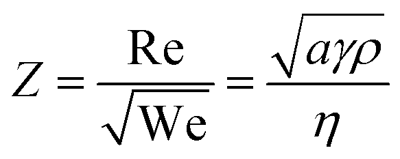
Following the seminal work of Bathurst et al.,13 CSD-based inkjet printing of PZT thin films was described in a number of publications.14–16 These works shed light upon the challenges related to inkjet printing. Indeed, several requirements need to be fulfilled for successful implementation of CSD in the IJP process. First, the rheological properties have to be adjusted to enable droplet formation. The dimensionless parameter Z related to the Reynolds (Re) and Weber (We) numbers is usually associated with this ability and describes the balance between surface tension and viscous forces of the ink.17 It is expressed as follows:
 | (1) |
In addition, it was shown that such a ternary solvent system also serves a purpose related to the ink drying behavior. The coffee ring effect refers to capillary flow-driven transport of material to the edge of a drying liquid film as the solvent evaporates.18 This effect is not desirable in printed film structures and can be counteracted by the presence of high-boiling-point co-solvents which redistribute the solute through an inward Marangoni flow.19,20
Control of surface wetting is also a crucial parameter. High-surface-energy substrates such as platinized silicon are affected by extreme ink spreading and therefore poor resolution (see Fig. S1, ESI†). Typical solutions to this issue are represented by surface modification with polymeric layers21 or self-assembled monolayers.15 Precise control of surface wettability can enable lithography-free printing resolution in the sub-100 nm range.22
Finally, it follows that modifications in the solution composition may bring about adaptations in the thermal post-printing steps. Similarly to conventional CSD processing, pyrolyzed layers should consist of metal oxide free from organic residues. Usually this decomposition is thermally induced by heating the dried film at ∼350 °C (lower than the crystallization temperature),7 but it can also be assisted by photochemical23 or combustion-based24 processes. We previously reported on inkjet-printed PZT thin films.15 Although encouraging when compared to similar works on inkjet printing,13,14,16 the electromechanical properties of our layers were inferior to state-of-the-art CSD-derived films, which could be ascribed to porosity originating from incomplete elimination of the high-boiling-point solvents during pyrolysis. This issue was not thoroughly addressed in previous works.
In this work, we report an investigation of the influence of pyrolysis conditions on the microstructure and properties of inkjet-printed PZT thin films. In particular, we correlate the amount of residual organics in the films after the pyrolysis stage with the porosity and properties of the final films crystallized at 700 °C. We show that it is possible to fabricate dense films with {111} preferential orientation and state-of-the-art electrical properties via inkjet printing. Finally, potential applications of these layers are exemplified by simple energy harvesters based on inkjet-printed PZT films.
2 Experimental procedures
2.1 Preparation and characterization of PZT precursor solutions
The PZT spin coating solution and the PZT ink were prepared based on the procedure described in Godard et al.15 Freeze-dried lead(II) acetate, zirconium(IV) butoxide and titanium(IV) isopropoxide were used as metal precursors. The stoichiometry of metal cations was such that Pb![[thin space (1/6-em)]](https://www.rsc.org/images/entities/char_2009.gif) :Zr:Ti = 1.10:0.53:0.47 (morphotropic phase boundary composition with 10% Pb excess). Acetylacetone (2 mol equiv.) was added to modify the Zr and Ti alkoxide precursors. After dissolution in 2-methoxyethanol, the mixture was refluxed under inert atmosphere and gentle stirring for 2 h. The solution was subsequently distilled and diluted with 2-methoxyethanol such that CZr + CTi = 0.3 mol L−1 (PZT spin coating solution). Finally, 2.3 mL of glycerol and 0.9 mL of ethylene glycol were added to 6.7 mL of this solution to obtain the 0.2 mol L−1 PZT ink.
:Zr:Ti = 1.10:0.53:0.47 (morphotropic phase boundary composition with 10% Pb excess). Acetylacetone (2 mol equiv.) was added to modify the Zr and Ti alkoxide precursors. After dissolution in 2-methoxyethanol, the mixture was refluxed under inert atmosphere and gentle stirring for 2 h. The solution was subsequently distilled and diluted with 2-methoxyethanol such that CZr + CTi = 0.3 mol L−1 (PZT spin coating solution). Finally, 2.3 mL of glycerol and 0.9 mL of ethylene glycol were added to 6.7 mL of this solution to obtain the 0.2 mol L−1 PZT ink.
Viscosity of the solutions was evaluated via the parallel plate method (plate diameter 50 mm and gap 1 mm) using an MCR 502 rheometer (Anton Paar, Austria), for a shear rate of 100 s−1 (steel cup filled with 2 mL of ink). The flow curves are presented in Fig. S2 (ESI†). Surface tension was determined using the pendant drop method. Pictures of 4 μL droplets hanging from 0.51 mm-diameter needles were recorded using an OCA 25 goniometer (DataPhysics, Germany) and processed using the free software OpenDrop.25 Thermogravimetric and differential thermal analyses of the solutions were carried out using an STA 409 PC thermal analyzer (Netzsch, Germany), with a heating rate of 10 °C min−1 under air atmosphere.
2.2 Printing and annealing process
The PZT ink was injected into a Dimatix DMCLCP-11610 cartridge (10 pL nominal drop volume, Fujifilm, Japan) through a 0.2 μm PTFE filter. The cartridge was mounted onto the printhead of a Ceradrop X-Serie (MGI Group, France) inkjet printer. The printhead temperature was set to 30 °C for optimal jetting. The jetting waveform is shown in Fig. S3 (ESI†). Platinized silicon wafers (sputtered Pt [100 nm]/sputtered and oxidized Ti [20 nm]/thermal SiO2 [500 nm]/Si) were cut into 3 × 1.5 cm2 substrates, which were degassed on a hot plate at 350 °C for 5 min before printing.All 16 nozzles of a DMCLCP-11610 cartridge (10 pL nominal volume) were used for printing three 25 × 4 mm2 rectangles with PZT ink. The droplet spacing along the x and y-axes was 15 μm and 254 μm (spacing between consecutive nozzles), respectively. This printing strategy has the advantage of depositing small volumes of ink per unit area on the substrate (∼3 nL mm−2), thus limiting lateral spreading of the ink despite the strong wetting (see Fig. S1, ESI†). No prior surface modification of the platinized silicon substrate was therefore performed. A profilometry measurement of the final crystallized film is shown in Fig. S4 (ESI†). The jetting frequency was 4 kHz and the printhead was kept 0.8 mm above the substrate. After printing, the wet film was dried at 175 °C for 1 min and pyrolyzed at temperatures ranging from 350 to 475 °C for 3 min. The next layer was printed on top of the previous one in the same conditions. After pyrolysis of the 12th layer, the film was crystallized in air at 700 °C for 5 min (50 °C s−1), which afforded a 200 nm-thick PZT film.
2.3 Characterization details
Fourier transform infra-red (FTIR) spectra were acquired on a Bruker Vertex 70 spectrometer (Bruker, USA). The PZT ink was analyzed in attenuated total reflectance (ATR) mode, while the dried, pyrolyzed and crystallized PZT films were characterized using a grazing angle objective (GAO). Spectra were processed with the software OPUS (average over 3 measurements for each condition). X-ray diffraction (XRD) patterns were recorded on a Bruker D8 diffractometer (Bruker, USA) in θ–2θ configuration using Cu-Kα radiation. X-ray reflectivity (XRR) patterns were recorded using a PANalytical X'Pert Pro diffractometer (PANalytical, Netherlands) with Cu-Kα radiation. Investigation of the microstructure was performed with a Helios NanoLab 650 (FEI, USA) scanning electron microscope (SEM). Sputtered 100 μm-diameter platinum top electrodes were patterned by lift-off photolithography. The electrodes were annealed at 400 °C for 10 min before electrical characterization to improve the interface between Pt and PZT. Ferroelectric and dielectric measurements were carried out using a TF Analyzer 2000 (aixACCT, Germany). Large-signal measurements of polarization-electric field loops were carried out at 100 Hz up to ±500 kV cm−1, while small-signal measurements of permittivity-electric field loops were carried out at 1 kHz with a small-signal amplitude of 100 mV, up to DC bias fields of ±500 kV cm−1. For each sample, electrical measurements were carried out on 5 different electrodes. The reported values are averages over these 5 measurements.2.4 Fabrication and characterization of energy harvesters
The fabrication of energy harvesters is based on the inkjet printing procedure described above. A single energy harvesting device consists of a 6 × 1 cm2 platinized silicon beam on which two 20 × 4 mm2 PZT rectangles were printed, 1 cm away from the edge (clamping area). The PZT films were pyrolyzed at 425 °C for 3 min. Five deposition cycles were performed to obtain 1 μm-thick PZT films. Sputtered 18.692 mm × 2.675 mm = 50 mm2 platinum top electrodes were patterned by lift-off photolithography on each of the PZT rectangles. A 3.0 g proof mass (0.02 € coin) was attached to the extremity using a hot-melt adhesive. After poling (200 kV cm−1, 10 min, 150 °C), the energy harvesters were tested using a dedicated setup (see Fig. 6a) based on a subwoofer (Pioneer TS-SW2002D2) equipped with a platform and a clamping system. A sine signal from a function generator (Agilent 33210A) amplified by a Pioneer GM-D8601 amplifier was used to drive the subwoofer. The output root mean square (RMS) voltage VRMS was measured with an oscilloscope (Tektronix TDS2004C) across a variable resistive load R connected in parallel with the sample terminals. The output power was calculated as follows: P = VRMS2/R.3 Results & discussion
3.1 Ink characterization
The ink formulation was described in a previous work.15 The physicochemical properties of a standard PZT spin coating solution and the PZT ink are presented in Table 1. The Z number was calculated using eqn (1) for a 10 pL nominal volume Fujifilm Dimatix DMP-11610 cartridge, whose nozzles are 21 μm-sided square channels. The spin coating solution has a Z-value of 13.4, while that of the ink was decreased down to 3.5 thanks to the addition of glycerol and ethylene glycol, bringing it into the jettable range, as shown in Fig. 1a. It has to be noted that these Z-values were evaluated for room temperature. In typical printing conditions, the printhead temperature is higher (Tprinthead = 30 °C). Although Z is expected to increase with temperature as a consequence of lower viscosity,17 it is assumed to stay within the jettable zone, as demonstrated by the excellent jetting quality of our PZT ink formulation across a wide frequency range as shown in the stroboscopic image of Fig. 1b. Since slight deviations in droplet velocity could be observed at the highest jetting frequencies (10 kHz), 4 kHz was selected in this study as compromise between printing time and jetting stability.| PZT SC solution | PZT ink | |
|---|---|---|
| Concentration (mol L−1) | 0.3 | 0.2 |
| Surface tension (mN m−1) | 32.5 | 34.2 |
| Density (g cm−3) | 1.05 | 1.11 |
| Viscosity (mPa s) | 2.0 | 8.1 |
| Z | 13.4 | 3.5 |
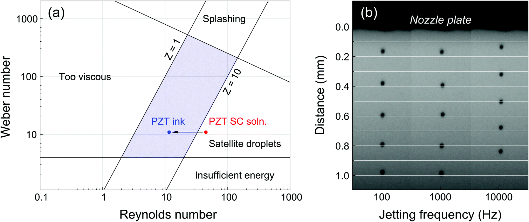 | ||
| Fig. 1 (a) Representation of the jettable range in terms of Weber and Reynolds numbers (adapted from Derby8) and effect of solvent modification on the jettability of PZT CSD precursor solutions. (b) Stroboscopic picture of PZT ink ejected using a DMC-11610 cartridge (50 μs pitch). Droplets ejected at 100 Hz and 1 kHz travel at ∼4 m s−1, while droplets ejected at 10 kHz travel close to 3.5 m s−1. | ||
Thermogravimetric analysis (TGA) coupled with differential thermal analysis (DTA) of the PZT spin coating solution and PZT ink is presented in Fig. 2. For the spin coating solution, drying is marked by a significant loss of mass and endothermic peak centered at ∼140 °C, corresponding to the evaporation of 2-methoxyethanol. In the case of the PZT ink, it is clear that the drying step is shifted towards higher temperatures. The initial loss of mass is associated with two endothermic events centered at ∼155 °C and ∼275 °C, which can be associated with the evaporation of 2-methoxyethanol and ethylene glycol up to 200 °C and the evaporation of glycerol between 250 and 300 °C, respectively. Decomposition of glycerol could also take place at temperatures below 300 °C,26 but the absence of a clear exothermic signature in the DTA signal suggests that its elimination from the system is mainly dominated by evaporation in this temperature range. The formation of azeotropic mixtures in this ternary solvent system cannot be excluded and could account for the absence of three distinct evaporation events.
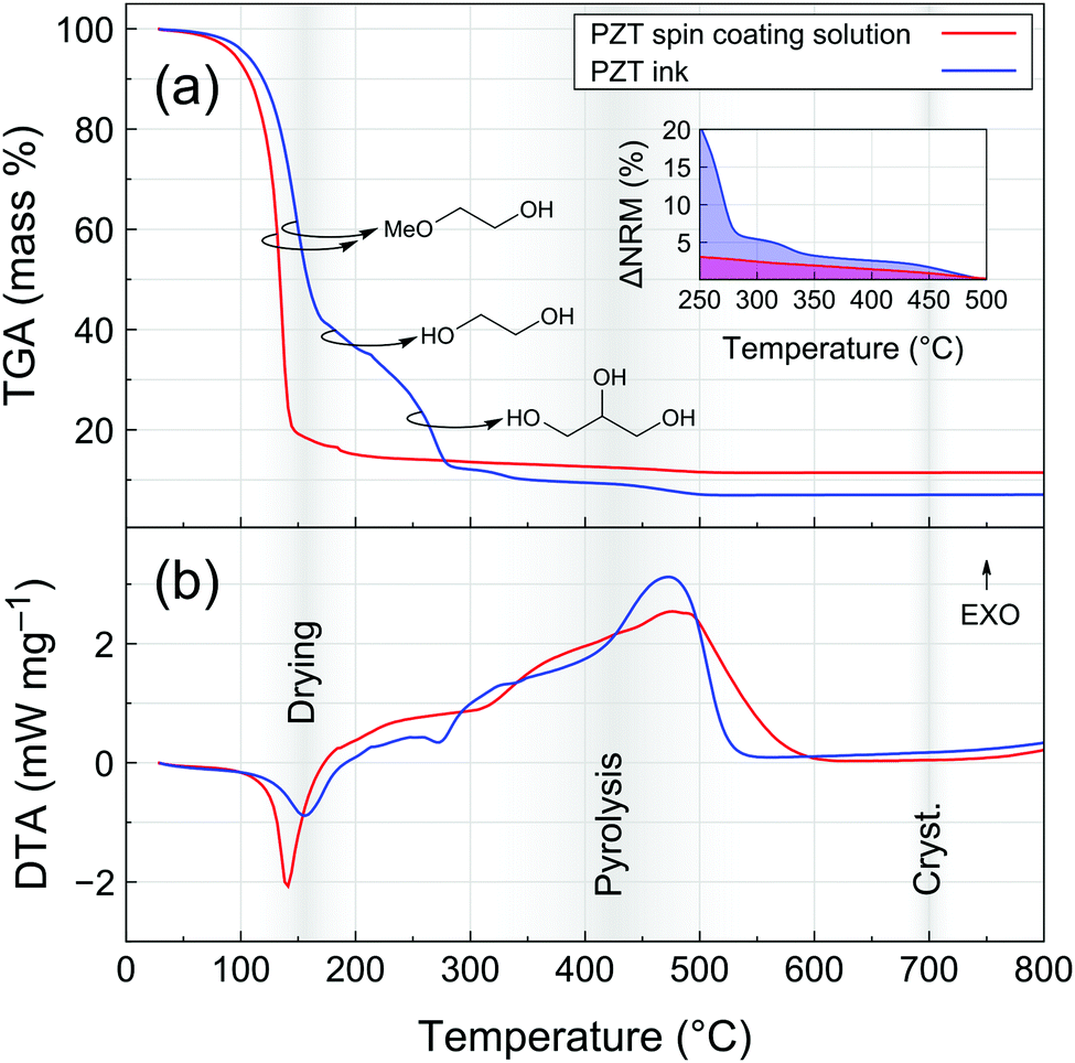 | ||
| Fig. 2 (a) Thermogravimetric analysis (TGA) coupled with (b) differential thermal analysis (DTA) of PZT spin coating solution and PZT ink. The inset of the TGA curve represents the normalized residual mass (ΔNRM = (m − mfinal)/(100 − mfinal), with m and mfinal expressed in %, where mfinal is the mass at 500 °C) in the 250–500 °C temperature range. The highlighted temperature ranges denote the temperatures used in the deposition process. | ||
A slight loss of mass is then recorded until 500 °C for both PZT precursor solutions. The broad exothermic contribution in this range can be associated to pyrolysis (decomposition of the remaining organics) and crystallization events. The inset of Fig. 2a shows mass variation in the 250–500 °C temperature range normalized with respect to the final residual mass (ΔNRM). From that representation, it is clear that the proportion of organic residual content in the PZT ink is always higher than that of the spin coating solution up to 500 °C.
Note that the thermal analysis was carried out with a constant temperature ramp of 10 °C min−1. The actual heat ramps experienced by samples under typical processing conditions are much higher due to the use of hot plates for drying and pyrolysis and rapid thermal annealing (RTA) for crystallization. Nevertheless, this analysis gives a clear hint about the differences in the way organics are eliminated from spin-coated and inkjet-printed PZT thin films. We therefore proceeded with a closer examination of the pyrolysis step in the case of inkjet-printed PZT films.
3.2 FTIR study of the influence of pyrolysis temperature and time
The Fourier transform infra-red (FTIR) spectrum of the PZT ink measured in attenuated total reflection (ATR) mode is shown in Fig. 3a. Absorption bands can be associated to the ink solvents, which are the main constituents at that stage (Fig. S5, ESI†). Characteristic bands corresponding to O–H and C–H stretching are found in the 3000–3600 cm−1 and 2800–3000 cm−1 ranges, respectively. In the fingerprint region of the spectrum, the strongest absorption bands in the 1000–1100 cm−1 range can be ascribed to aliphatic alcohol and ether moieties.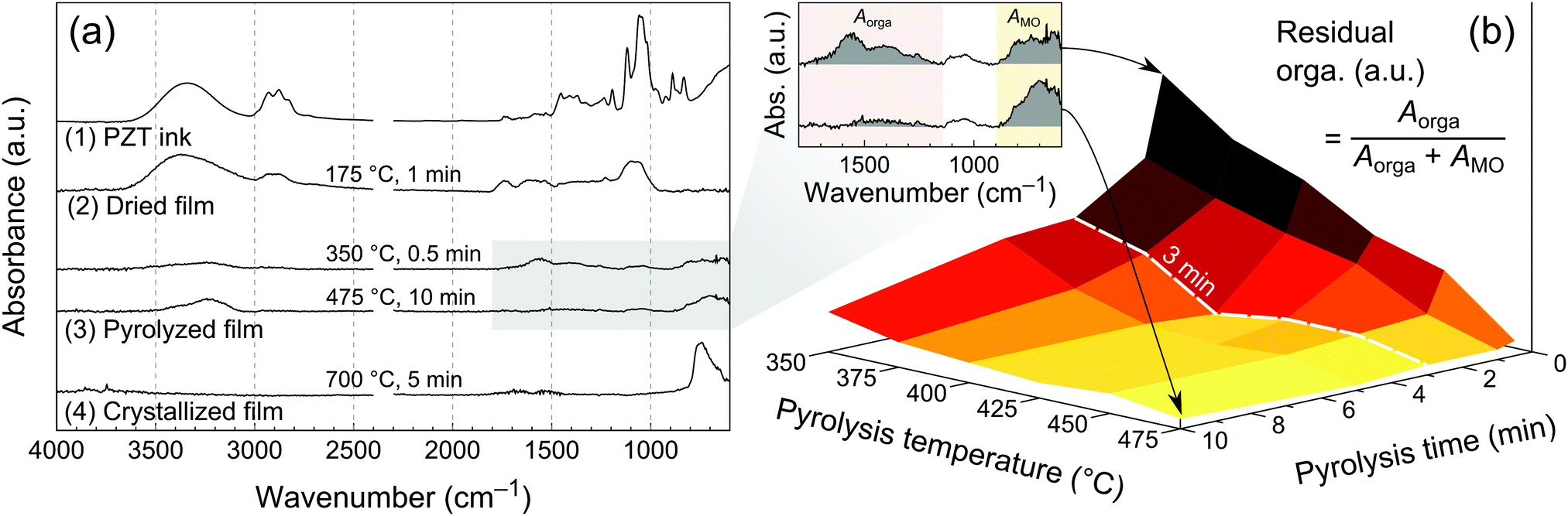 | ||
| Fig. 3 (a) FTIR spectra illustrating transformations of the PZT ink from liquid to crystallized state: (1) FTIR spectrum of the PZT ink acquired in ATR mode and downscaled for comparison with FTIR spectra acquired in grazing angle mode, namely a single layer printed on platinized silicon and (2) dried at 175 °C for 1 min, followed by (3) pyrolysis at 350 °C for 0.5 min or 475 °C for 10 min and finally after (4) crystallization at 700 °C for 5 min. (b) The region of interest between 600 and 1800 cm−1 in the FTIR spectra of pyrolyzed films was used to draw the correlation between pyrolysis temperature and time and amount of residual organics. | ||
In order to study the chemical transformations of the film from its wet state after printing to the crystallized form, we used FTIR spectroscopy in grazing angle mode (see Experimental), Fig. 3a. The chemical signature of the ink is mostly preserved in the dried film (175 °C for 1 min), strongly suggesting the presence of residual glycerol and probably ethylene glycol. FTIR spectra for two pyrolysis conditions are shown in Fig. 3a, namely 350 °C for 0.5 min and 475 °C for 10 min. Two groups of absorption bands can be identified in the fingerprint region of the spectrum at 1100–1800 cm−1 and 600–800 cm−1. The first one can be attributed to the remaining organics (presumably oxidized carbon species such as carboxylates and carbonates),27 while the second to metal–oxygen bonds.28 The latter absorption band becomes more intense and sharper in the crystallized layer (suggesting transformation from amorphous to crystalline state), while the one attributed to organics vanishes, as can be expected from the TGA data.
In order to study the influence of pyrolysis temperature and time on the amount of residual organics in the pyrolyzed films, we fabricated a series of samples by printing a single layer of PZT ink, drying at 175 °C for 1 min, then we pyrolyzed them between 350 and 475 °C for a period ranging from 0.5 min to 10 min. FTIR spectra were then recorded and processed. The amount of residual organics was associated with the relative integrated intensity of absorption bands in the 1100–1800 cm−1 region of the FTIR spectra, according to eqn (2).
 | (2) |
The results are shown in Fig. 3b, where this ratio was plotted as a 3D surface. In this landscape representation, the elevated areas correspond to high residual organics, while the bottom flat area is associated with low organic content. The boundaries of the latter are Tpyro ≥ 400 °C and tpyro ≥ 3 min, and indicate the minimal pyrolysis parameters required to achieve the lowest organic content. Interestingly, it appears that extending the pyrolysis time to 10 min at 350 °C or 375 °C still results in a residual organic content, which sets the requirement for Tpyro ≥ 400 °C. These results also provide a qualitative indication of the pyrolysis kinetics as a function of temperature. For temperatures lower than 450 °C, pyrolysis only tends towards completion after 3 min, as a significant organic residue is still present after 0.5 min and 1 min of pyrolysis.
3.3 Microstructural characterization
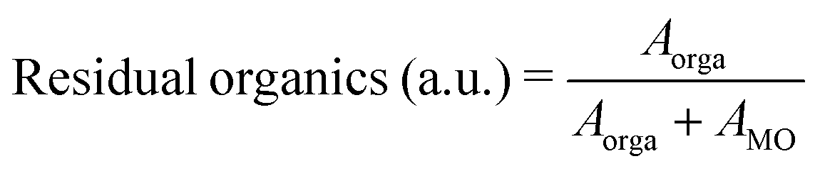
The FTIR study was carried out for very thin layers (<20 nm) resulting from a single deposition. Thicker films are required in order to assess their quality in terms of morphology and functional properties. We therefore went on to study the microstructure of 200 nm-thick films (12 depositions) pyrolyzed at different temperatures along the 3 min line (path drawn in Fig. 3b), as it allowed for reasonable processing durations.Scanning electron microscopy (SEM) cross sections of the PZT thin films crystallized at 700 °C are presented in Fig. 4a. Porosity is present in the films pyrolyzed at 350 °C and 375 °C, whereas the films pyrolyzed at 400 °C and higher temperatures are comparatively denser. The density was also assessed by X-ray reflectivity (XRR) measurements (Fig. S6, ESI†). The inset of Fig. 4b shows the improvement of density with pyrolysis temperature. The extracted densities were normalized to the densities for the lowest pyrolysis temperatures and expressed as a percentage variation (Δρnorm). It can be seen that above a threshold between 400 and 425 °C, density improves by about 9%.
 | ||
| Fig. 4 (a) SEM cross sections and (b) XRD patterns of crystallized inkjet-printed (IJP) PZT thin films on platinized silicon (12 layers) showing the evolution of texture and microstructure as function of pyrolysis temperature for a pyrolysis time of 3 min (corresponds to the path represented in Fig. 3b). Crystallization was performed at 700 °C. The XRD pattern of a spin-coated (SC) PZT film grown on platinized silicon is shown for comparison. Peaks marked with an asterisk are due to the substrate. The Pt(111) peak is masked for clarity. The inset of (b) shows the improvement of normalized relative density (ρnorm) extracted from XRR measurements. | ||
This observation can be linked with the previous study (Fig. 3b), inferring a strong correlation between porosity and the presence of residual organics in the layers after pyrolysis. In that case, the elimination of organics occurs during the crystallization stage. The rapid evolution of gaseous decomposition products as a result of fast heating rate (50 °C s−1) and high crystallization temperature (700 °C) hinders film densification,29 resulting in a granular microstructure with substantial inter-granular porosity, which is also visible in SEM surface micrographs shown in Fig. S7 (ESI†). Comparison of SEM cross sections of the films after pyrolysis and crystallization (Fig. S8, ESI†) confirms that large pores develop during crystallization, in particular at the PZT/platinum interface. In contrast, the crystallization of printed PZT films with minimal residual organics after pyrolysis gives rise to dense columnar microstructure.
X-ray diffraction (XRD) patterns recorded in θ–2θ geometry show that all the printed PZT films are crystallized in the perovskite phase (Fig. 4b). Films pyrolyzed at 350 °C exhibit random orientation. Interestingly, significant {100} orientation is detected in the films pyrolyzed at 375 °C. However, for pyrolysis temperatures equal to and higher than 400 °C, the {111} texture becomes predominant. PZT films grown on unseeded platinized silicon may adopt the texture of the underlying Pt(111) electrode in some cases.30 Furthermore, it is known that the development of {111} texture can be associated with the appearance of a transient intermetallic PtxPb at the interface, formed as a result of reduction of Pb(II) to Pb(0) in the presence of remaining organics (reducing environment) and diffusion into the Pt electrode. In the case of the PZT films pyrolyzed at 350 °C, it is probable that the crystallization proceeds via homogeneous nucleation due to the concomitant evolution of gases, disrupting substrate-templated growth and resulting in random orientation. This effect is less pronounced for the film pyrolyzed at 375 °C, where some degree of {100} and {111} texture is observed. For the sake of comparison, we also show in Fig. 4b the XRD pattern of a spin-coated PZT film, which was deposited on pristine platinized silicon (without a seed layer). This film was dried at 130 °C for 3 min, pyrolyzed at 350 °C for 3 min and crystallized at 700 °C for 5 min. A significant degree of {111} texture can be detected, similarly to what is observed for the inkjet-printed films pyrolyzed at T ≥ 400 °C.
3.4 Electromechanical characterization
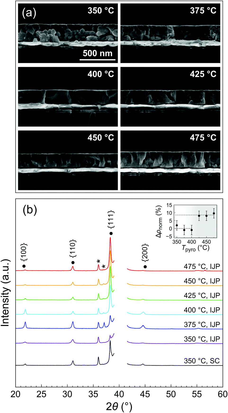
Polarization–electric field (P–E) loops for the series of PZT films is presented in Fig. 5a. A typical ferroelectric response could be measured for all the samples. The porous samples pyrolyzed at 350 and 375 °C exhibit the lowest remanent polarization, with Pr = 8.0 and 10.2 μC cm−2, respectively. Both remanent polarization (Pr) and maximum polarization (Pmax) increase with increasing pyrolysis temperature (see inset of Fig. 5a), while the coercive field remains practically unchanged throughout the series (Ec ∼ 60 kV cm−1). Note that some dependence of the coercive field on porosity could be expected. However, the relationship between coercive field and porosity is not trivial and often nonlinear, as it can be influenced by the level of porosity and its distribution in the film.31,32 PZT films pyrolyzed at the highest temperature (475 °C) display a remanent polarization of 23.7 μC cm−2.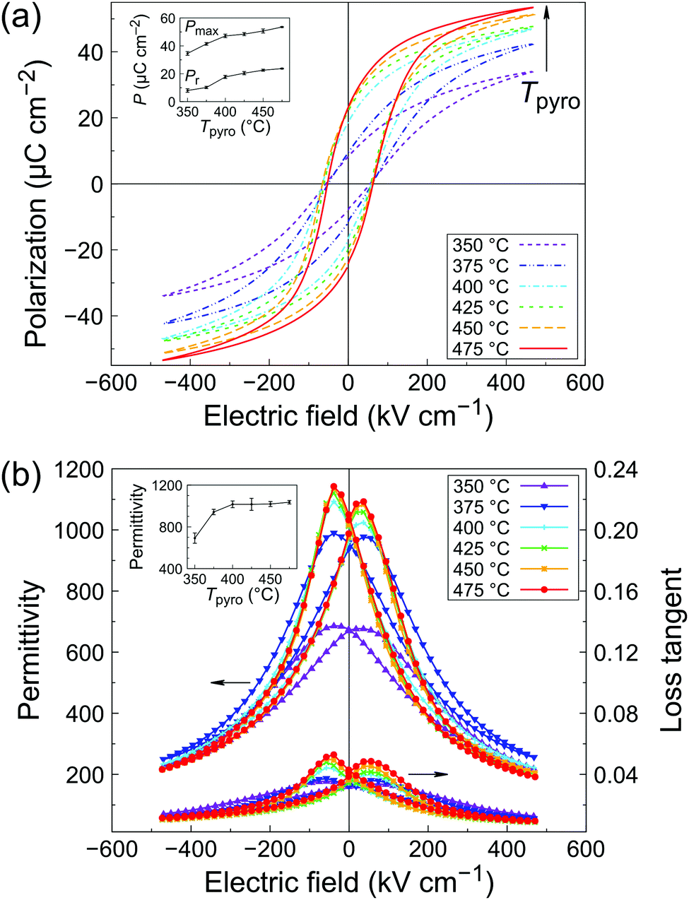 | ||
| Fig. 5 (a) Polarization–electric field at 100 Hz and (b) permittivity–electric field loops at 1 kHz (VAC = 100 mV) measured for inkjet-printed 200 nm-thick PZT films as function of the pyrolysis temperature Tpyro (pyrolysis time tpyro = 3 min). | ||
Permittivity–electric field (ε–E) characteristics are shown in Fig. 5b. As seen in the inset, permittivity at zero bias increases with increasing pyrolysis temperature until 400 °C, after which a plateau is observed (ε′ ∼ 1000, see inset of Fig. 5b). Dielectric losses also slightly increase with increasing pyrolysis temperature, from 0.034 to 0.042. This behavior is typical of ferroelectric thin films and mainly comes form extrinsic contributions (domain walls).33 At high bias fields, films pyrolyzed at 350 and 375 °C exhibit a higher loss tangent than the rest of the series. This could be ascribed to the higher leakage current at high fields in the P–E measurements, as shown in Fig. S9 (ESI†). A higher amount of defects in the porous films could explain this trend. Films pyrolyzed at T ≥ 400 °C display the best electrical properties, which correlates well with the observed densification and columnar microstructure of the films. The results are compiled in Table S10 (ESI†) and compared with the literature. The electrical properties of our inkjet-printed PZT films are in line with state-of-the-art solution-derived films.
In order to test the functionality of our inkjet-printed PZT films, we implemented them in a simple unimorph energy harvester (EH) illustrated in Fig. 6a. The printing process described herein (Tpyro = 425 °C) was performed five times, yielding a final PZT thickness of 1 μm. After poling, the device was mounted on a shaker. The resonance curve and power versus load resistance curves are shown in Fig. 6b. The device resonant frequency is 102 Hz, in good agreement with the theoretical value predicted by the Euler–Bernoulli beam model (see Fig. S11, ESI†). The maximum output power at resonance is 5.8 μW for a 6 kΩ resistive load. In addition, the device was tested for an extended period of time to assess aging. No degradation of the properties was observed after 25 × 106 cycles, as seen in Fig. S12 (ESI†). Considering that the active material volume for a single device is 0.1 mm3, we report a power density of 58 μW mm−3, which is comparable to devices previously described in the literature,38 as shown in Table 2. In these examples, PZT was deposited either via spin coating35 or rf-magnetron sputtering,36,37 whereas our work features fully inkjet-printed piezoelectric layers.
 | ||
| Fig. 6 (a) Description of the energy harvester based on inkjet-printed PZT films. (b) Energy harvester output power and voltage as function of load resistance. The inset shows normalized output voltage as function of frequency. Resonance of the cantilever beam occurs at 102 Hz. | ||
| Ref. | Fang et al.34 | Morimoto et al.35,36 | Yeo et al.37 | This work |
| Year | 2006 | 2010 | 2016 | 2019 |
| Process | Spin coating | Sputtering | Sputtering | Inkjet printing |
| Thickness (μm) | 1.64 | 2.8 | 3 (bimorph) | 1 |
| Texture | — | (001) | (001) | {111} |
| P r (μC cm−2) | 14 | 30 | 40 | 20 |
| E c (kV cm−1) | 30 | 50 | 65 | 48 |
| ε′ | — | 166 | 210 | 1200 |
| tanδ |
— | — | 0.03 | 0.05 |
| Power (μW) | 2.2 | 5.3 | 149 | 5.8 |
| Frequency (Hz) | 609 | 126 | 6 | 102 |
| Acceleration (m s−2) | 10 | 5 | 1 | 50 |
| Active volume (mm3) | 0.78 | 0.26 | 1.2 | 0.1 |
| Power density (μW mm−3) | 7.6 | 21 | 124 | 58 |
We estimate that growing 0.1 mm3 of PZT for a single EH device via our inkjet printing process only requires ∼20 μL of ink. Even with purging and priming operations, the total ink consumption to fabricate a single device is well below 1 mL, making this process remarkably cost-efficient compared to conventional spin coating deposition. These promising results provide a solid basis for further developments, such as improving process time-efficiency by reducing the number of processing steps (i.e. printing thicker layers via tailoring of the ink formulation and printing strategy) and controlling the texture of the printed layers.
4 Conclusions
In this study, we present the development of a precursor ink for lead zirconate titanate (PZT) thin films from a conventional precursor solution modified with high-boiling-point co-solvents. The presence of the latter in the solution was shown to modulate processing conditions. In particular, FTIR analysis of pyrolyzed films revealed that the elimination of residual organics in the layers could be achieved by pyrolysis for 3 min at T ≥ 400 °C. This observation was correlated with porosity in the final crystallized layers, as well as electrical properties. Dense, 200 nm-thick {111}-textured films with Pr = 23 μC cm−2, Ec = 60 kV cm−1, ε′ = 1000 and tanδ = 0.04 were fabricated by inkjet printing. Finally, we implemented the printed piezoelectric layers in a simple energy harvesting device, which provided a 5.8 μW power output at 6 kΩ, thus demonstrating the potential of inkjet printing technology for the fabrication of low-cost electromechanical transducers.
Conflicts of interest
There are no conflicts to declare.Acknowledgements
The authors acknowledge financial support from the Luxembourgish National Research Fund (FNR) under projects CO-FERMAT (FNR/P12/4853155/Kreisel), TRAPIZT (C-PPP-17/MS/11814049/TRAPIZT/Defay) and HARVESTORE (FNR/INTER/ANR/18/12618689/Defay). The authors also wish to thank Benoît Marcolini and Régis Vaudemont for performing thermal analyses, Jean-Baptiste Chemin for the deposition of platinum top electrodes, Maryline Moreno for the measurement of FTIR spectra and Mathieu Gérard for the development of the test bench for energy harvesting.Notes and references
- P.-H. Cazorla, O. Fuchs, M. Cochet, S. Maubert, G. Le Rhun, Y. Fouillet and E. Defay, Sens. Actuators, A, 2016, 250, 35–39 CrossRef CAS.
- F. Filhol, E. Defaÿ, C. Divoux, C. Zinck and M.-T. Delaye, Sens. Actuators, A, 2005, 123–124, 483–489 CrossRef CAS.
- S.-G. Kim, S. Priya and I. Kanno, MRS Bull., 2012, 37, 1039–1050 CrossRef CAS.
- S. Roundy and P. K. Wright, Smart Mater. Struct., 2004, 13, 1131–1142 CrossRef.
- P. Muralt, J. Micromech. Microeng., 2000, 10, 136–146 CrossRef CAS.
- G. L. Brennecka, J. F. Ihlefeld, J.-P. Maria, B. A. Tuttle and P. G. Clem, J. Am. Ceram. Soc., 2010, 93, 3935–3954 CrossRef CAS.
- N. Bassiri-Gharb, Y. Bastani and A. Bernal, Chem. Soc. Rev., 2014, 43, 2125–2140 RSC.
- B. Derby, Annu. Rev. Mater. Res., 2010, 40, 395–414 CrossRef CAS.
- J. Windle and B. Derby, J. Mater. Sci. Lett., 1999, 18, 87–90 CrossRef CAS.
- T. Wang and B. Derby, J. Am. Ceram. Soc., 2005, 88, 2053–2058 CrossRef CAS.
- D. Kuscer, O. Noshchenko, H. Uršič and B. Malič, J. Am. Ceram. Soc., 2013, 96, 2714–2717 CrossRef CAS.
- T. Bakarič, B. Malič and D. Kuscer, J. Eur. Ceram. Soc., 2016, 36, 4031–4037 CrossRef.
- S. P. Bathurst, H. W. Lee and S. G. Kim, 2008 IEEE 21st International Conference on Micro Electro Mechanical Systems, 2008, pp. 391–394 Search PubMed.
- O. Machida, A. Shimofuku, R. Tashiro, A. Takeuchi, Y. Akiyama and E. Ohta, Jpn. J. Appl. Phys., 2012, 51, 09LA11 CrossRef.
- N. Godard, S. Glinšek, A. Matavž, V. Bobnar and E. Defay, Adv. Mater. Technol., 2019, 4, 1800168 CrossRef.
- A. Matavž, A. Benčan, J. Kovač, C.-C. Chung, J. L. Jones, S. Trolier-McKinstry, B. Malič and V. Bobnar, ACS Appl. Mater. Interfaces, 2019, 11, 45155–45160 CrossRef PubMed.
- D. Jang, D. Kim and J. Moon, Langmuir, 2009, 25, 2629–2635 CrossRef CAS PubMed.
- R. D. Deegan, O. Bakajin, T. F. Dupont, G. Huber, S. R. Nagel and T. A. Witten, Nature, 1997, 389, 827–829 CrossRef CAS.
- E. Tekin, B.-J. de Gans and U. S. Schubert, J. Mater. Chem., 2004, 14, 2627–2632 RSC.
- A. Matavž, R. C. Frunza, A. Drnovšek, V. Bobnar and B. Malič, J. Mater. Chem. C, 2016, 4, 5634–5641 RSC.
- A. Matavž, V. Bobnar and B. Malič, Langmuir, 2017, 33, 11893–11900 CrossRef PubMed.
- C. W. Sele, T. von Werne, R. H. Friend and H. Sirringhaus, Adv. Mater., 2005, 17, 997–1001 CrossRef CAS.
- I. Bretos, R. Jiménez, J. Ricote and M. L. Calzada, Chem. Soc. Rev., 2018, 47, 291–308 RSC.
- M.-G. Kim, M. G. Kanatzidis, A. Facchetti and T. J. Marks, Nat. Mater., 2011, 10, 382–388 CrossRef CAS PubMed.
- J. D. Berry, M. J. Neeson, R. R. Dagastine, D. Y. Chan and R. F. Tabor, J. Colloid Interface Sci., 2015, 454, 226–237 CrossRef CAS PubMed.
- B. Dou, V. Dupont, P. T. Williams, H. Chen and Y. Ding, Bioresour. Technol., 2009, 100, 2613–2620 CrossRef CAS PubMed.
- R. M. Silverstein, F. X. Webster, D. J. Kiemle and D. L. Bryce, Spectrometric Identification of Organic Compounds, John Wiley & Sons, Inc., Hoboken, NJ, 8th edn, 2014 Search PubMed.
- Y. Wang and J. J. Santiago-Avilés, Nanotechnology, 2004, 15, 32–36 CrossRef CAS.
- Y. Bastani and N. Bassiri-Gharb, J. Am. Ceram. Soc., 2012, 95, 1269–1275 CrossRef CAS.
- S. Trolier-McKinstry and P. Muralt, J. Electroceram., 2004, 12, 7–17 CrossRef CAS.
- V. Stancu, M. Lisca, I. Boerasu, L. Pintilie and M. Kosec, Thin Solid Films, 2007, 515, 6557–6561 CrossRef CAS.
- Y. Zhang, J. Roscow, R. Lewis, H. Khanbareh, V. Y. Topolov, M. Xie and C. R. Bowen, Acta Mater., 2018, 154, 100–112 CrossRef CAS.
- A. Tagantsev, V. Sherman, K. Astafiev, J. Venkatesh and N. Setter, J. Electroceram., 2003, 11, 5–66 CrossRef CAS.
- H. B. Fang, J. Q. Liu, Z. Y. Xu, L. Dong, L. Wang, D. Chen, B. C. Cai and Y. Liu, Microelectron. J., 2006, 37, 1280–1284 CrossRef.
- K. Morimoto, I. Kanno, K. Wasa and H. Kotera, Sens. Actuators, A, 2010, 163, 428–432 CrossRef CAS.
- I. Kanno, H. Kotera and K. Wasa, Sens. Actuators, A, 2003, 107, 68–74 CrossRef CAS.
- H. G. Yeo, X. Ma, C. Rahn and S. Trolier-McKinstry, Adv. Funct. Mater., 2016, 26, 5940–5946 CrossRef CAS.
- R. Xu and S.-G. Kim, PowerMEMS, 2012, pp. 464–467 Search PubMed.
Footnote |
| † Electronic supplementary information (ESI) available. See DOI: 10.1039/c9tc05228c |
| This journal is © The Royal Society of Chemistry 2020 |