
Electrochemical and compositional characterization of solid interphase layers in an interface-modified solid-state Li–sulfur battery†
Syed Atif
Pervez‡
 *a,
Bhaghavathi P.
Vinayan‡
*a,
Musa Ali
Cambaz
a,
Georgian
Melinte
b,
Thomas
Diemant
c,
Tobias
Braun
a,
Guruprakash
Karkera
a,
R. Jürgen
Behm
ac and
M.
Fichtner
*ab
*a,
Bhaghavathi P.
Vinayan‡
*a,
Musa Ali
Cambaz
a,
Georgian
Melinte
b,
Thomas
Diemant
c,
Tobias
Braun
a,
Guruprakash
Karkera
a,
R. Jürgen
Behm
ac and
M.
Fichtner
*ab
aHelmholtz Institute Ulm, Helmholtzstraße, 11, 89081, Ulm, Germany. E-mail: syedatif.pervez@partner.kit.edu; vinayan.parambath@kit.edu; m.fichtner@kit.edu
bInstitute of Nanotechnology (INT), Karlsruhe Institute of Technology (KIT), Hermann-von-Helmholtz-Platz 1, 76344 Eggenstein-Leopoldshafen, Germany
cInstitute of Surface Chemistry and Catalysis, Ulm University, Albert-Einstein-Allee 47, 89081 Ulm, Germany
First published on 14th July 2020
Abstract
The Li+ transport kinetics at the solid–solid electrode|electrolyte interfaces are crucial for the stable and durable performance of solid-state batteries (SSBs). A poor interface due to mechanical problems and/or (electro-)chemical instabilities will curtail the performance of such batteries. Herein, we present a detailed study on the interfaces of a lithium–sulfur (Li–S) SSB with a Li anode, Li–garnet (LLZO) solid electrolyte (SE), and a sulfur–carbon composite as the cathode. Interlayer gels based on ionic liquids were introduced to improve the interfacial properties of the system. For Li symmetric cells, the strategy resulted in a decrease in cell resistance by about a factor of five and stable voltage profiles with low overpotentials (∼300 mV at 0.4 mA cm−2 after >450 hours). Furthermore, the LLZO SE efficiently blocked the polysulfide shuttle to the Li anode. Due to the advantageous features of the design, good electrochemical performance was obtained, where the Li–S SSB delivered an initial discharge capacity of ca. 1360 mA h gsulfur−1 and a discharge capacity of ca. 570 mA h gsulfur−1 after 100 cycles. Detailed electrochemical and compositional characterization of the interphase layers was performed at the Li anode and sulfur cathode interfaces through X-ray photoelectron spectroscopy (XPS), applying depth-profiling techniques, and scanning transmission electron microscopy (STEM). The results revealed the presence of interphase nano-layers with varying thicknesses on the LLZO surface which contained organic and inorganic species.
Introduction
To meet the ever-increasing energy storage demand in electric vehicles and stationary storage systems, a substantial increase in the energy densities of the current Li-ion batteries (LIBs) is essential. This motivates researchers to develop alternate chemistries superior to those based on conventional LiFePO4 and LiCoO2 cathode materials. In this regard, Li–S batteries stand out among their peers because of their high energy capacity. Li–S batteries operate via a conversion based reduction reaction of sulfur (S) with Li (16Li+ + S8 + 16e− ↔ 8Li2S), leading to an exceptionally high theoretical energy density of ∼2500 W h kg−1—five times more than that of conventional LIBs (387 W h kg−1 for LiCoO2/graphite batteries).1 Additionally, the abundant availability and environment friendly nature of S makes it an attractive cathode material. Despite enormous potential, the practical application of Li–S batteries with liquid electrolyte systems is hindered by issues such as large volumetric changes of S and Li2S (∼80%), and the insulating nature of S and Li2Sx. The reduction of S to Li2S during the discharge cycle follows a multistep reduction reaction process, including the formation of highly soluble long-chain polysulfides (Li2Sn, 4 ≤ n ≤ 8), which are produced as intermediates of this process. Such polysulfides shuttle towards the Li anode which leads to chemical short-circuits and an unstable SEI formation on the Li anode.2 These polysulfides dry out the liquid electrolyte during long-term cycling which severely affects the performance of the cell. The situation is further complicated by the high loading of S on the cathode (>70% S loading, >3 mgsulfur cm−2) during cycling, which intensifies polysulfide dissolution and volume changes, and enforces structural and morphological variations. Overall, such characteristics of the Li–S system result in self-discharge phenomena, poor capacity retention and low coulombic efficiency.3 On the other hand, the instability of Li anodes with organic liquid electrolytes is also well-known.4,5 Li forms mossy or needle like dendritic structures upon cycling which can potentially pierce the conventional polypropylene separators, resulting in internal short circuits of the cells. To solve these problems, various strategies have been explored for both the S and the Li electrodes. For example, synthesizing S composites with carbonaceous materials6 and/or surface coating the cathodes with conducting polymers7 have helped in trapping polysulfides. Tuning the properties of organic electrolytes using different additives has been beneficial too.8,9 On the Li side, efforts include ex situ coating of Li with polymer- and carbon-based materials or formation of artificial solid–electrolyte interface (SEI) layers to protect the Li electrode from reacting with the organic liquid electrolyte.10Utilization of ceramic SE based separators is also an interesting strategy that can potentially solve problems associated with the S cathode and Li anode. Thanks to their high shear modulus, both the polysulfide shuttle and the Li dendrite growth can be mechanically suppressed. Among various inorganic ceramic SEs, Li–garnet (LLZO) is of particular interest since it offers a relatively high (electro)-chemical stability with Li metal, a much wider potential window compared to other SEs,11 and a high shear modulus (61 GPa for LLZO; 4.2 GPa for Li).12 However, the surface impurities/roughness and brittle nature of LLZO SE restrict its intimate contact with Li and other solid-state cathode materials.13,14 With S as the cathode material, the electrode/electrolyte integration will be even more challenging considering the enormous volumetric expansion during the conversion reaction with Li. In this regard, surface modification strategies including the use of thin nanometric layer coatings, and 3D interfacial architectures, or the implementation of polymer, gel and liquid interlayers have been used to keep the electrode|SE contacts intact and stabilize the interfacial ionic transport.15–18 Using Li ion conducting gel/liquid interlayers instead of using solid interlayers may prove to be an even better strategy due to their inherent tendency to penetrate through the porous structures and hence to access a greater surface area of the composite cathode.19
Herein, we have designed a solid-state Li–S storage system based on a sulfur–carbon composite positive electrode, LLZO SE and a Li negative electrode. To improve the interfacial properties of the SSB, interlayer gels containing ionic liquids (IL) and a Li-salt have been introduced at electrodes|SE interfaces. The LLZO SE acts as a solid barrier to mechanically block the polysulfide shuttle. Owing to such features, good battery performance has been demonstrated, where the cells exhibited an initial discharge capacity of ca. 1360 mA h gsulfur−1 and a discharge capacity of ca. 570 mA h gsulfur−1 after 100 cycles. The chemical composition of the interphase layer, both of its surface and of deeper regions, was characterized by XPS, applying depth profiling techniques, including both sides (cathode & anode) of the LLZO SE. High-resolution transmission electron microscopy (HRTEM) and energy dispersive X-ray spectroscopy (EDS) spectrum imaging were also conducted to obtain information about the thickness and composition of the interphase layer. The data suggest the presence of amorphous interfacial nano-layers on the LLZO surface with varying thickness. The layers contain both organic and in-organic species originated from the decomposition of the IL, Li-salt and organic solvents.
Results & discussion
Prior to its integration with the electrodes, various properties of the LLZO SE such as the microstructure, crystalline phase and ionic conductivity were characterized. To improve the Li ion conductivity in the parent LLZO structures, Nb5+ was doped at the Zr4+ sites to create Li+ vacancies, and Ba2+ was doped at the La3+ sites to increase the Li+ concentration.20,21Fig. 1a shows the cross-sectional SEM image of the LLZO SE pellet. A dense microstructure was formed by the uniaxial pressing and the subsequent sintering steps. The relative density of the LLZO pellet was ∼95% which was the ratio of the theoretical density calculated using the lattice parameter derived from XRD and the real density measured using a He gas pycnometer. XRD analysis of the LLZO SE (Fig. 1b) reveals the cubic phase of LLZO, where most of the diffraction peaks relate to the parent Li–garnet phase “Li5La3Nb2O12” with the space group Ia![[3 with combining macron]](https://www.rsc.org/images/entities/char_0033_0304.gif) d.22 A small peak at ∼2θ = 30 degree corresponds to the presence of BaZrO3 impurities.23 LLZO exists in cubic and tetragonal polymorphs. The former is typically obtained at higher sintering temperatures (>1000 °C), and exhibits about two orders of magnitude higher Li-ion conduction.24Fig. 1c shows the Nyquist plots of a Au|LLZO|Au quasi-blocking cell obtained at room temperature. Au metal was sputtered on either side of the LLZO pellet to obtain uniform contacts. The plots were fitted with a resistor–capacitor (constant phase element) circuit and a series capacitor. By fitting the high frequency (5–0.5 MHz) semi-circle, we obtain a capacitance of ∼2.7 × 10⁻¹⁰ F which could be attributed to the bulk and grain-boundary contributions to Li+ transport in the SE.25 In the low frequency range (<100 Hz), we observe a linear increase which reflects the quasi-blocking effect of the Au electrodes. From the low-frequency intercept of the semi-circle with the x-axis we determine a bulk resistance (RB) of ∼640 ± 1.4 Ω cm2. When using l as the thickness of the SE pellet and a as the electrode surface area, the ionic conductivity σ was calculated using the formula: σ = l/RBa, which was found to be ∼1.5 × 10⁻⁴ S cm−1. Further, σ is plotted as a function of increasing temperature T in Fig. 1d and the relationship follows an Arrhenius behavior26 as expressed by the following equation
d.22 A small peak at ∼2θ = 30 degree corresponds to the presence of BaZrO3 impurities.23 LLZO exists in cubic and tetragonal polymorphs. The former is typically obtained at higher sintering temperatures (>1000 °C), and exhibits about two orders of magnitude higher Li-ion conduction.24Fig. 1c shows the Nyquist plots of a Au|LLZO|Au quasi-blocking cell obtained at room temperature. Au metal was sputtered on either side of the LLZO pellet to obtain uniform contacts. The plots were fitted with a resistor–capacitor (constant phase element) circuit and a series capacitor. By fitting the high frequency (5–0.5 MHz) semi-circle, we obtain a capacitance of ∼2.7 × 10⁻¹⁰ F which could be attributed to the bulk and grain-boundary contributions to Li+ transport in the SE.25 In the low frequency range (<100 Hz), we observe a linear increase which reflects the quasi-blocking effect of the Au electrodes. From the low-frequency intercept of the semi-circle with the x-axis we determine a bulk resistance (RB) of ∼640 ± 1.4 Ω cm2. When using l as the thickness of the SE pellet and a as the electrode surface area, the ionic conductivity σ was calculated using the formula: σ = l/RBa, which was found to be ∼1.5 × 10⁻⁴ S cm−1. Further, σ is plotted as a function of increasing temperature T in Fig. 1d and the relationship follows an Arrhenius behavior26 as expressed by the following equation | (1) |
 | ||
| Fig. 1 (a) Cross-sectional SEM image of the LLZO SE. (b) XRD pattern for the synthesized LLZO compound confirming the formation of a cubic phase. * Indicates the BaZrO3 impurity phase (c) Nyquist plot for LLZO SE at room temperature. (d) Arrhenius plot of the bulk conductivity of the LLZO SE over a temperature range of 25–100 °C. | ||
To identify the potential and role of the interlayers in improving the Li|LLZO interfacial properties, Li symmetrical cells (Li|LLZO|Li) were assembled with and without gel interlayers and EIS spectra were recorded at room temperature. As described in more detail in the experimental section, the interlayers were composed of the ionic liquid Pyr14TFSI (IL) with LiTFSI as Li salt and organic solvents. Special care was taken to use a minimal amount (5 μL) of gel ion conductors at the interfaces as the aim was to only wet the solid–solid interfaces. For each cell, the Nyquist plots (Fig. 2a) consisted of high frequency (5–0.1 MHz) and low frequency (kHz to Hz) semicircles that correspond to the bulk/grain-boundary and the Li|LLZO interface resistances, respectively. The resistance values were extracted from the x-axis intercepts of the plots. After introduction of the interlayers, we observed a reduction in the interface resistance by approximately a factor of 5, as the total resistance (RTotal) of the Li|LLZO|Li cells decreased from ∼6800 to ∼1350 Ω cm2 (Table 1). This suggests that the ion conducting IL gels fill up the micro voids at the solid–solid interfaces which were otherwise highly resistant to the ionic transport (Fig. S2, ESI†). Previous studies also showed the success of similar interlayer concepts in lowering the interface resistance and improve the Li+ ion transport.15,16,29
 | ||
| Fig. 2 Electrochemical characterization of Li|LLZO|Li cells with and without IL interlayers. (a) Nyquist plots obtained at room temperature; (b) Li stripping/plating chrono-amperometric voltage profiles at different current densities ranging from 0.1–0.4 mA cm−2; (c, d) enlarged views of the voltage profiles highlighting the overpotential and random oscillations. The sudden drop in the cell voltage points towards ‘soft short-circuits’. | ||
| Li|LLZO|Li cell | Overpotential (V) | R Total at 25 °C (Ω cm2) | |||
|---|---|---|---|---|---|
| After 50 h at 0.1 mA cm−2 | After 200 h at 0.2 mA cm−2 | After 330 h | After 400 h at 0.4 mA cm−2 | ||
| With interlayers | 0.12 | 0.21 | 0.31 at 0.3 mA cm−2 | 0.33 | 1350 |
| Without interlayers | 0.67 | 1.30 | Short-circuited at 0.2 mA cm−2 | — | 6800 |
In the next step, the electrochemical stability of Li|LLZO interfaces with and without interlayers was tested by Li stripping/plating experiments. The comparison of the resulting voltage profiles for symmetrical Li|LLZO|Li cells is shown in Fig. 2b. The cells with interlayers displayed stable voltage profiles for more than 450 hours of continuous Li stripping/plating. The average overpotential values are listed in Table 1. Compared to Li|LLZO|Li with interlayers, a much higher overpotential was observed for cells without interlayers, as shown in the enlarged view in Fig. 2c. After 50 h of Li stripping/plating at 0.1 mA cm−2 the overpotential for the cells without interlayers was ∼0.67 V, while it was only ∼0.12 V with interlayers. Furthermore, the overpotential steadily increased with time for the cells without the interlayers. For example, at 0.2 mA cm−2 the overpotential increased from ∼1.2 V at 120 h to ∼1.60 V at 300 h, an indication of continuous deterioration of the interface during successive cycles. Such high overpotentials are likely to induce excessive stress on the Li|LLZO interface, thus initiating Li dendrites and accelerating their growth across the SE. This was evident from the sudden voltage drop at ∼330 h which suggests the onset of short-circuiting events, which will continue in the following cycles (Fig. 2d). This is consistent with the findings in other studies which reported adverse effects of an unstable Li|LLZO interface on the Li cyclability in the form of high overpotentials and Li dendrite formations.30,31 In contrast, the cells with interlayers show lower overpotentials, e.g., ∼0.31 V at 0.3 mA cm−2 after 330 h and ∼0.33 V after 400 h, and are able to withstand a current density as high as 0.4 mA cm−2. At all currents, the voltage profiles remained stable without noticeable deviations or irregularities, suggesting that the integrity of the interfaces was not affected. This may also suggest the formation of electronically insulating interphase layers that provide passivation and stop further decomposition of the electrolyte.32 Further, the lack of short-circuits indicates an effective suppression of the Li dendrite formation. Such improved interfacial properties of the system were possible by overcoming the physical and (electro-)chemical limitations imposed by the complex Li|LLZO interface. The IL based interlayers, firstly, filled up the micro voids at the solid–solid interface hence providing physical pathways for Li+ ion transport as illustrated in the schematic in Fig. S2.† Secondly, owing to the stability of Li with the PYR14TFSI ionic liquid,33 an electrochemically stable interphase layer was formed which facilitated the ionic transport. The chemical stability between LLZO and the IL gels was also investigated. The idea was to find out whether any chemical reactions occur between the chemical components of the interlayers and LLZO that could result in the formation of decomposition products. XRD analysis by comparing pristine LLZO and the one exposed to gels based on the IL, LiTFSI and organic solvents for one week showed similar diffraction patterns (Fig. S3, ESI†), indicating that at least no new crystalline phases were formed.
For full cell testing, sulfur–carbon composite cathodes were used. It is well known that S, lithium disulfide and other reaction intermediates have poor electronic conductivity.34 To improve this, S nanoparticles were impregnated into a nitrogen doped carbon matrix (from now on labelled ‘S/NC’); a detailed account on the synthesis of the cathode was given in our previous report.35 The carbon composite matrix with good electronic conductivity and a high surface area (700 m2 g−1) contained graphene and multiwall carbon nanotubes in an equal weight ratio. The morphology of the cathode material is illustrated in the SEM image shown in Fig. S4.† Further, thermo-gravimetric analysis (TGA) shows a S loading of ∼55 wt% in the S/NC cathode (Fig. S5, ESI†).
Fig. 3a shows the room temperature charge/discharge voltage profiles of a Li|LLZO|S/NC cell. The IL interlayers were introduced at both the anode and the cathode interfaces. The cells were cycled at a rate of 0.1C (1C = 1672 mA gsulfur−1) in a voltage window of 1.5–3 V. Two plateau voltage profiles (at ∼2.35 V, and ∼2.1 V) indicate the conversion based reduction reaction of S with Li, which is associated with the octahedral S8 ring opening and the formation of high- and low-order polysulfides (Li2Sx, x = 8–1), finally leading to lithium disulfide/lithium sulfide (Li2S2/Li2S). The discharge capacities for the 1st, 2nd, 50th, 100th cycles were ca. 1360, 1330, 712, and 570 mA h gsulfur−1, respectively. In the initial 30 cycles, noticeable capacity decay and a low coulombic efficiency (∼97%) were observed (Fig. 3b). In the following 70 cycles, the capacity stabilized and the coulombic efficiency increased to ∼99.8%. The initial lower coulombic efficiency may be attributed to the formation of the interphase layers on the Li anode and on the cathode side, resulting in an irreversible capacity loss.36 It is also evident in Fig. 3c that the voltage hysteresis increased from ∼300 mV to ∼500 mV in the initial 30 cycles, but stayed stable afterwards up to 100 cycles. We also tested the cell at 50 °C to check the impact of higher temperatures on the electrochemical performance. As shown in Fig. S6,† the capacity increased from ∼570 mA h gsulfur−1 (at 100th cycle, 25 °C) to ∼690 and ∼670 mA h gsulfur−1 for the next cycles (101th, and 102nd). The voltage hysteresis of the cell also reduced from ∼500 mV to ∼250 mV. This suggests that at higher temperatures better electrochemical performance may be achieved for the Li/S SSB, although in the current work our focus has been on room temperature performance.
 | ||
| Fig. 3 (a–c) Electrochemical performance of a Li|LLZO|S/NC cell tested at 0.1C-rate at 25 °C, (a) galvanostatic charge/discharge voltage profiles of the 1st, 2nd, 50th and 100th cycle, (b) cycle performance and coulombic efficiency, and (c) voltage hysteresis and average charge/discharge voltages of the cell from the 1st to 100th cycle. (d) Cross-sectional FIB-SEM image and elemental map of the interface between LLZO SE and the S/NC cathode of the cycled cell. | ||
Using LLZO ceramic as a separator is advantageous in physically blocking the polysulfide shuttle towards the Li anode. The higher order polysulfides (Li2Sx, x ≥ 4) created during the reduction reaction between the S based cathode and the IL based gel layers were confined to the S/NC|LLZO interface. As evident from the elemental maps in focused-ion beam (FIB) SEM images (Fig. 3d), LLZO SE is free from any S species. Nevertheless, the polysulfides, formed at the cathode interface may react with LLZO and create a more resistive interphase compared to the Li side. This prompted us to check the impedance contribution from each electrode separately. We compared the total impedances for Li|LLZO|S/NC full cells and Li|LLZO|Li symmetrical cells with interlayers after initial cycling as shown in Fig. S7.† A slightly higher impedance was observed for the Li|LLZO|S/NC cells which implies that the interphase layer formed at the S/NC|LLZO interface is more resistive than at the Li|LLZO interface.
In the next step, we analyzed the elemental composition and the chemical state (oxidation state) of the elements in the Li|LLZO and S/NC|LLZO interphase layers by XPS. For these measurements, we used the LLZO SE pellets after removal from the cycled electrochemical cells and subsequent washing with isopropanol. XPS spectra were recorded from both sides of the pellets, either that previously in contact with the Li anode or with the S/NC cathode side. Since XPS is a surface sensitive method, which probes only ∼3–5 nm of the outermost surface region, we acquired depth profiles of the elemental composition in the surface-near region by repeated XPS measurements after successive Ar+ ion sputter etching treatments. Overall, XPS spectra were recorded before sputtering and after sputtering times of 3, 7, and 20 minutes, resulting in total sputtering times of 0, 3, 10, and 30 min. Under the given conditions, the sputtering rate is expected to be ∼1 nm min−1. To get more information on the chemical state of the main elements in the interphase layer, the results of the detail spectra were analyzed by peak fits. Fig. 4 shows the spectra recorded on the Li|LLZO side, and the data of the S/NC|LLZO side are shown in Fig. S8.† The binding energies of the individual peaks which were used in the fit and the assigned species are also listed in Table 2.
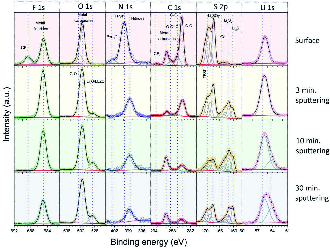 | ||
| Fig. 4 Detail XPS spectra of the solid interphase layer at the Li|LLZO interface. The spectra were recorded at the original surface and after 3, 10 and 30 minutes of Ar+ ion sputtering. | ||
| Elements | Peak positions (eV) | Chemical species | |
|---|---|---|---|
| Lithium side | S/NC side | ||
| C1s | 284.8 | C–C | C–C |
| 286.3 | C–O–C | C–O–C | |
| 288.4 | O–C![[double bond, length as m-dash]](https://www.rsc.org/images/entities/char_e001.gif) O O |
O–CO |
|
| 290.0 | Metal carbonates (e.g., Li2CO3) | Metal carbonates (e.g., Li2CO3) | |
| 293.0 | CF2/CF3 | CF2/CF3 | |
| F1s | 685.0 | Metal fluorides (e.g., LiF) | Metal fluorides (e.g., LiF) |
| 688.7 | Organic fluorine (example –CF2/–CF3) | Organic fluorine (example –CF2/–CF3) | |
| Li1s | 54.2 | Li in LLZO | Li in LLZO |
| 55.6 | Other Li species | Other Li species | |
| N1s | 398.7 | Nitrides | — |
| 399.8 | TFSI− | TFSI− | |
| 402.4 | Pyr14+ | Pyr14+ | |
| S2p | 168.8/170.0 | TFSI− | TFSI− |
| 167.0/168.2 | LixSOy | LixSOy | |
| 163.7/164.9 | Internal S of polysulfides | Internal S of polysulfides | |
| 161.9/163.1 | Disulfides (e.g., Li2S2)/terminal S of polysulfides | Disulfides (e.g., Li2S2)/terminal S of polysulfides | |
| 160.2/161.4 | Metal sulfides (e.g., Li2S) | Metal sulfides (e.g., Li2S) | |
| O1s | 529.6 | LLZO/Li2O | LLZO/Li2O |
| 531.6 | CO |
CO |
|
| Metal carbonates (e.g., Li2CO3) | Metal carbonates (e.g., Li2CO3) | ||
| 532.5 | C–O | C–O | |
Fig. 5 displays the results of the elemental concentrations obtained for the two sides of LLZO electrolyte pellets as a function of the sputtering time. For the side in contact with the Li anode (Fig. 5b), the C content decreases sharply from 27 to 12 at% in the first sputtering step and is further reduced to 7 at% in the following steps. On the other hand, the concentrations of Li and O rise substantially upon sputtering and both arrive at close to ∼40 at% after the last sputtering step (removal of ∼30 nm material). At the same time, the F content increases initially (after 3 min of sputtering) but then decreases again, while the amount of N and S decreases slowly step-by-step upon sputtering. Finally, after the second sputtering step (removal of ∼10 nm material), small features of the metal ions in the Nb, Ba-doped LLZO (i.e., Zr, Nb, Ba and La denoted as ‘metals’ in Fig. 5) can be detected. Their intensity increases substantially in the spectra after the last sputtering step, leading to a total concentration of these four elements of ∼3 at%. These results indicate on the one hand that the interphase layer is at some points rather thin (∼10 nm). On the other hand, however, the persistence of clearly interphase-related elements such as F, together with the rather low concentration of the LLZO metals after the last sputtering step, shows that the interphase layer is of varying thickness. Further conclusions regarding the distribution of organic and inorganic species in the interphase layer will be drawn after the presentation and discussion of the XP spectra.
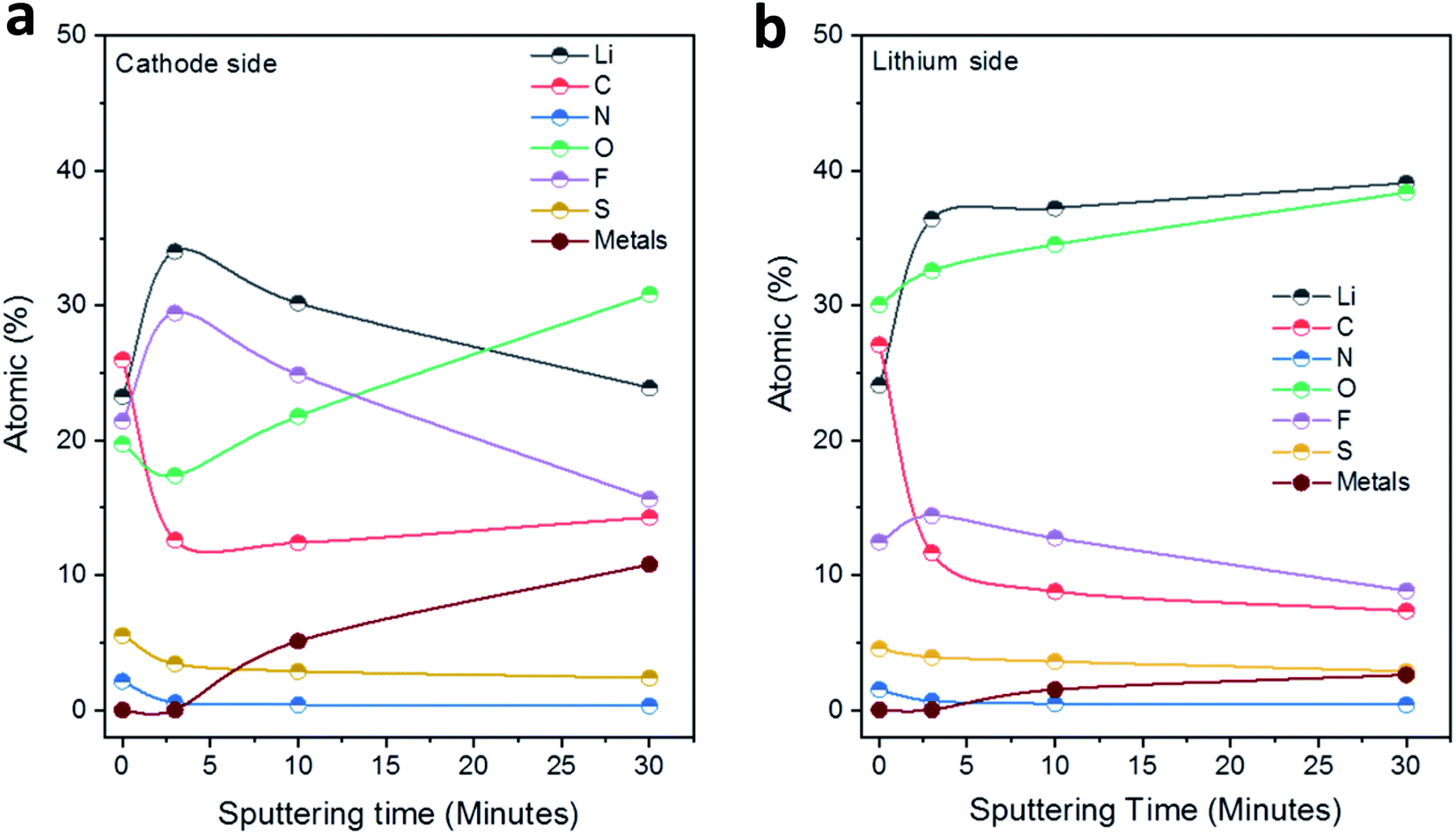 | ||
| Fig. 5 Development of the elemental concentrations (at%) in the solid interphase layers at the (a) S/NC|LLZO and (b) Li|LLZO interfaces as a function of the total sputtering time. | ||
For the Li|LLZO side, the C1s detail spectrum of the original interphase surface, before sputter etching, was dominated by a peak at 284.8 eV, which is assigned to C–C/C–H groups. Further peaks at 286.4, 288.4, 290.0 and 293.0 eV are attributed to C–O, CO, (inorganic) carbonate (CO32−) and CFx species, respectively. In the spectrum recorded after the first sputtering step, the carbonate peak at 290.0 eV had by far the largest intensity, while that of all other peaks decreased substantially. Only the C–C/C–H peak at 284.8 eV still had a notable intensity. The spectra recorded after the subsequent sputtering steps showed essentially the same result. These finding are corroborated by the detail spectra of the O1s region. They show two peaks at 531.5 and 532.5 eV before sputtering, which are assigned to CO/metal carbonate and C–O species, respectively. After sputtering, the peak at 531.5 eV remained and dominated the O1s spectra. Additionally, another peak appeared in the spectra after sputtering at a lower binding energy (528.6 eV), which we relate to the presence of metal oxide species (Li2O and LLZO). Going to the F1s region, the spectra recorded before sputtering showed two main peaks at 685.0 and 688.6 eV, which we attribute to metal fluorides (i.e., LiF) and CFx groups (in TFSI− or its decomposition products), respectively. After sputtering the peak assigned to CFx functional groups disappeared completely, while the metal fluoride peak at a lower binding energy persisted. The S2p spectrum recorded before sputtering is dominated by two peak doublets, which we assign to TFSI− (169.3/170.5 eV) and to oxidized decomposition products of it (e.g., LixSOy; 167.1/168.3 eV). After sputtering, new features appeared at a lower binding energy, which we relate to (metal) sulfide species, and which grew in intensity with increasing sputtering time. Next, for the measurements in the N1s region, before sputtering a dominant peak at 399.8 eV, which is related to the N atom of the TFSI− anion, and a much smaller feature at 402.4 eV due to the N atom in the Pyr14+ cation of the ionic liquid were shown. After sputtering, a new peak was detected at 398.7 eV, which we assign to nitride species. Finally, it may be noted that the detail spectra of the LLZO constituents (Zr3d, La3d, etc.) appearing after the last sputtering step (Fig. S9, ESI†) were in all cases dominated by features of fully oxidized species.37 In the case of Zr and Nb, there were in addition small contributions from reduced species, which are most probably a result of sputter-induced reduction processes.
The spectra and the elemental concentrations obtained for the side of the electrode, which was in contact with the S/NC cathode, showed in general similar features and trends as were observed on the Li side (Fig. 5a and S8, ESI†). For example, the spectra in the O1s and F1s region showed before sputtering a very similar result with features related to C–O and CO/metal carbonate (O1s region) species or metal fluoride and CFx species, respectively, while after sputtering the CO/carbonate (O1s region) and metal fluoride (F1s region) peaks were observed again (together with a small additional feature due to metal oxide species in the O1s region). Still, slight differences could also be noted. For example, the spectra in the C1s region showed also an increase in the peak related to metal carbonates (at 290.0 eV) upon sputtering, though the C–C/C–H peak remained a major contribution in the spectra of this side. The peak positions and associated chemical species at the Li|LLZO side and S|LLZO side are summarized in Table 2.
To provide further evidence of the presence of interphase layers, we carried out STEM analysis of the cycled LLZO particles that was interfaced to the Li anode. The STEM-HAADF image reveals the presence of interphase layers around the LLZO particles (Fig. 6a). Elemental mapping obtained through EDS spectrum imaging shows that the interphase is rich in S, F, C and O species while LLZO has a dominant concentration of La and Zr. S and F follow the same spatial distribution inside the interphase with minor differences registered in the distribution of O (Fig. S10, ESI†). The cumulated EDS spectra presented in Fig. 6b show that the interphase region has a chemical composition dominated by C, S, F and O that is substantially different from that of the LLZO particles. Note that Li is undetectable using conventional EDS detectors. The HRTEM image in Fig. 6c also reveals an amorphous interphase layer on the LLZO particles with variable thickness (range ca. 5–15 nm) as highlighted by the dashed lines. This agrees well with the XPS analysis where the metal ions (i.e., Zr, Nb, Ba and La) in LLZO were detected only after the second sputtering step (removal of ∼10 nm material). Inspection of the selected region of LLZO reveals the lattice fringes with a d spacing of 3.45 Å (inset Fig. 6c), which corresponds to the (321) hkl plane of the cubic LLZO phase. Moreover, the fast Fourier transform (FFT) images in Fig. 6c and the selected are electron diffraction patterns shown in Fig. S11† prove the cubic structure of the LLZO phase and its high crystallinity. In a higher magnification HRTEM image (Fig. S12, ESI†), another lattice spacing d = 2.09 Å of the (611) plane of cubic LLZO appears.
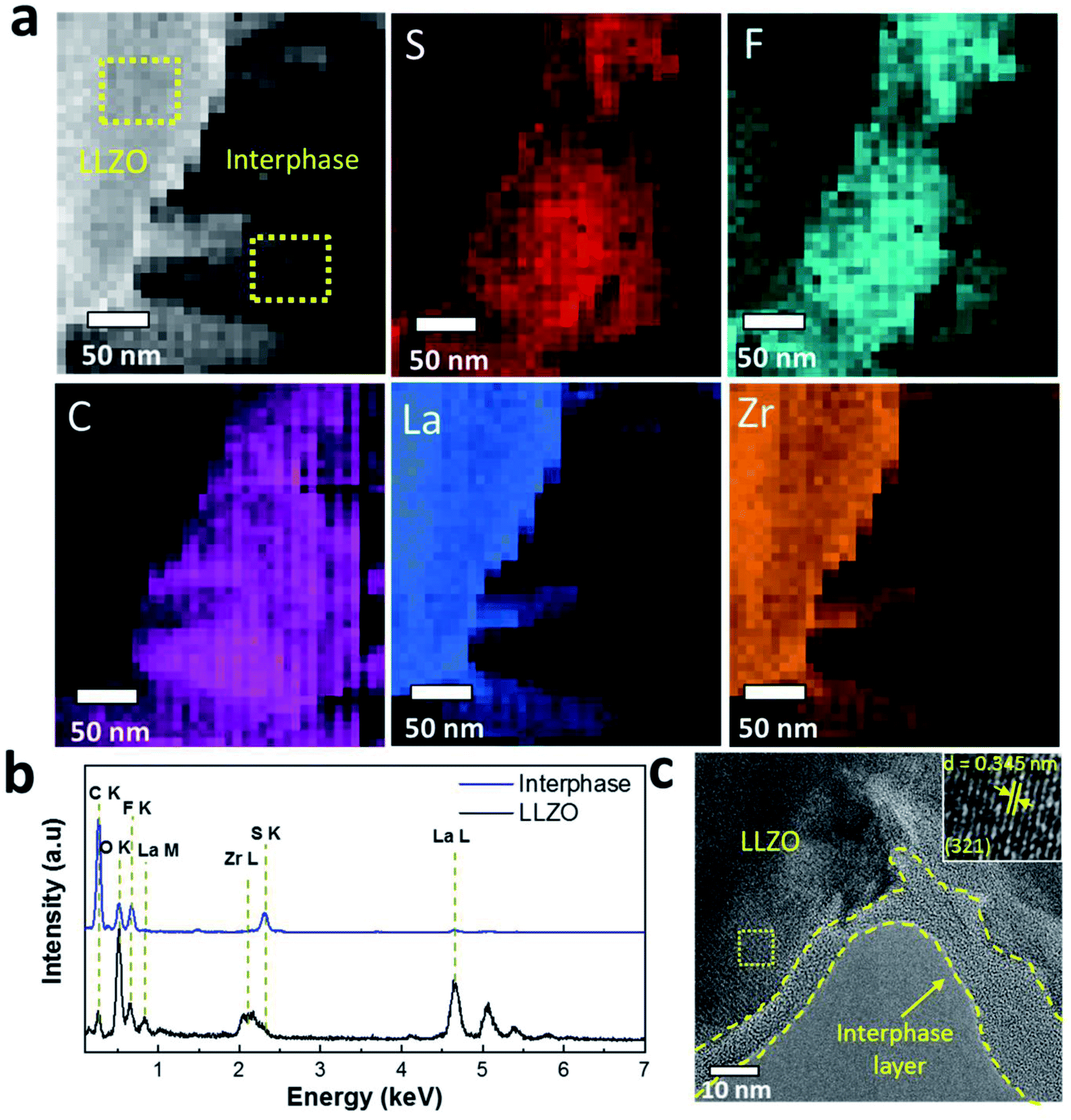 | ||
| Fig. 6 STEM and EDS spectrum imaging of cycled LLZO SE particles. (a) STEM-HAADF image of the analyzed LLZO particle-interphase area and corresponding elemental maps extracted from the spectrum imaging data for S, F, C, La and Zr. (b) Integrated EDS spectra from the regions highlighted in ‘a’. (c) HRTEM image revealing the presence of an amorphous solid interphase layer on the LLZO SE particles. The inset shows lattice fringes for LLZO. | ||
Overall, XPS and STEM analyses confirm the presence of amorphous solid interphase layers on the LLZO surface which are rich in S, F, C and O species and in the nano-meter range. The interphase layers are of varying thickness. A significant decrease in the carbon content upon sputtering, together with the clear increase of the content of inorganic (metal) carbonate and fluoride species is observed. The development of the elemental concentrations demonstrates that the outermost part of the interphase layer contains mostly organic species, while the inner part (close to the LLZO surface) mainly consists of inorganic species (cf. schematic depiction Fig. 7).
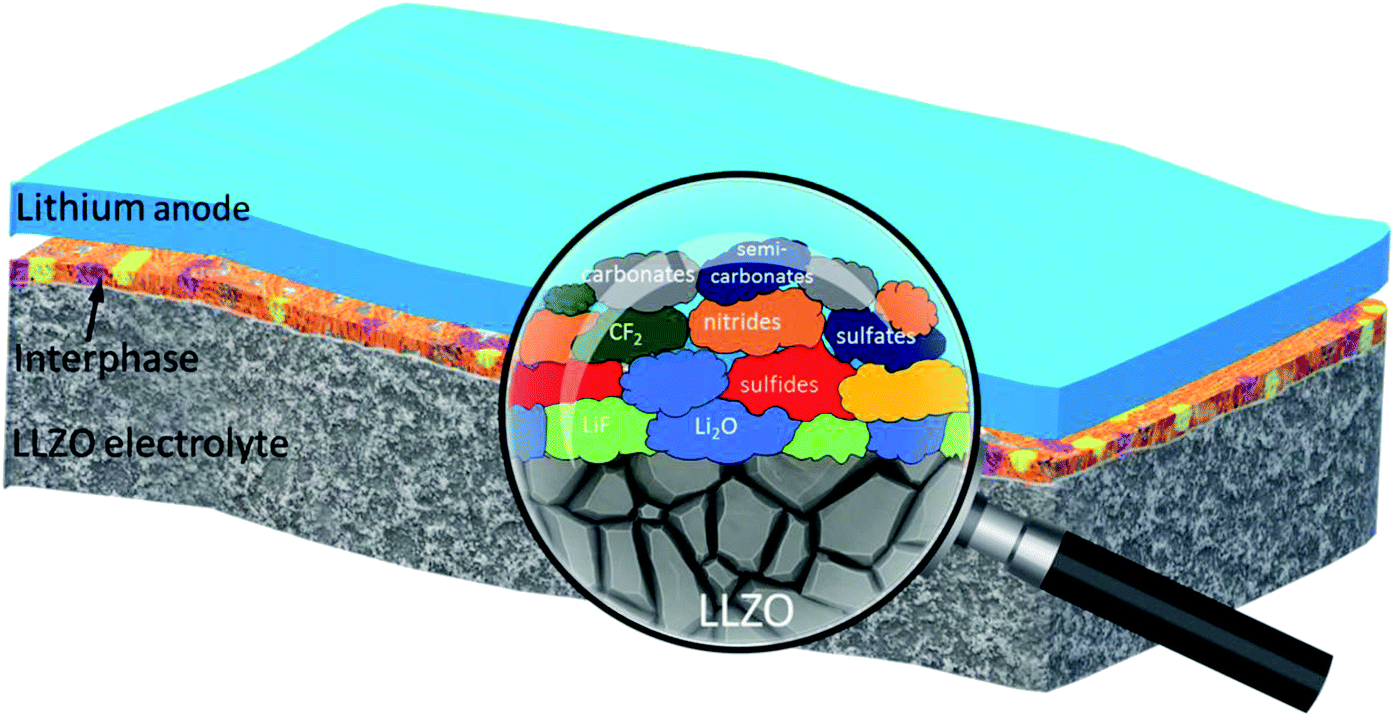 | ||
| Fig. 7 Schematic illustration of the solid interphase layer at the Li|LLZO interface. The ‘magnified’ view depicts the type of chemical species that builds up the interphase layer. The cathode interphase layers (not shown in the figure) contained similar chemical species. | ||
Conclusion
In summary, we have presented a detailed electrochemical and compositional characterization of solid interphase layers in a Li|LLZO|S/NC solid-state battery. To improve the interfacial properties, IL based gel interlayers were introduced both at the anode and at the cathode sides. This resulted in a significantly lower Li|LLZO interfacial resistance, a stable Li reversibility in the electrolytes for more than 450 hours at a high current density of 0.4 mA cm−2, and a good battery performance with an initial discharge capacity of ca. 1360 mA h gsulfur−1 and a discharge capacity of ca. 570 mA h gsulfur−1 after 100 cycles. The LLZO solid separator could successfully confine polysulfides to the S/NC cathode and effectively prevented the dissolution of polysulfides to the Li side. Furthermore, key information on the composition and thickness of the solid interphase layers was extracted by XPS and STEM techniques. The nano-layers formed on either side of the LLZO SE interfaced with Li and S/NC cathodes, were amorphous in nature, varied in thickness and consisted of outer layers which were rich in carbonaceous organic species and inner regions dominated by inorganic species, respectively.Experimental
Synthesis of solid electrolyte
LLZO with a nominal composition of Li6.5La2.5Ba0.5ZrNbO12 was prepared by a solid-state reaction method. In a typical synthesis, stoichiometric amounts of La2O3 (99.99%, Alfa Aesar, pre-heated at 900 °C for 12 hours), Ba(NO3)2 (99%, Alfa Aesar), ZrO2 (99%, Alfa Aesar), Nb2O5 (99.5%, Alfa Aesar), and LiNO3 (99%, Alfa Aesar, 10 wt% extra to make up for the Li loss during high temperature sintering) were properly milled in 2-propanol with a planetary ball mill (Pulverisette, Fritsch, Germany) at 200 rpm for 6 hours. The metal salts decomposed upon heating of the powder mixture at 700 °C for 6 hours in air. The obtained powder was ball-milled again to ensure homogeneous mixing and then uniaxially pressed (Specac UK) into pellets and then sintered at 900 °C for 20 h. Afterwards the pellets were ground, re-milled, and dried as an intermediate step. The resulting powder was then pelletized for the final sintering step at 1100 °C for 6 hours. To prevent Li loss during high temperature sintering, the pellets were covered with mother powder. To get the desired dimensions, the pellets were polished with Si-carbide sand paper (grit size 400) in an argon environment to obtain a thickness of ca. 500 μm and a geometric area of ca. 0.785 cm2.Preparation of the cathode material
The synthesis of the layer graphene/MWNT hybrid structures was carried out as described in one of our previous reports.35 The nitrogen doping of the (graphene-multiwall carbon nanotube) hybrid structure (NC) was achieved by nitrogen plasma treatment. The sulfur was loaded within the NC host matrices by melt infiltration at 155 °C under an argon gas atmosphere. Detailed information about the synthesis procedure is given in our previous report.35Synthesis of electrolyte interlayer gels
The electrolyte interlayer gels were synthesized by dissolving 1 M lithium bis(trifluoromethanesulfonyl)imide (LiTFSI, Sigma-Aldrich Battery grade) in a mixture of ionic liquid (N-methyl-N-butyl pyrrolidinium-bis(trifluoromethanesulfonyl)imide (Pyr14TFSI)) and organic solvents (anhydrous-1,3-dioxolane (DOL, Alfa Aesar), and anhydrous dimethoxyethane (DME, Sigma-Aldrich)) in an argon environment (O2 < 0.1 ppm and H2O < 0.1 ppm). The higher concentration of the Li-salt increased the viscosity of the liquids and transformed them into gels. The synthesis procedure is described in detail in our previous report.38Characterization
The X-ray diffraction (XRD) measurements were conducted in a Stadi P diffractometer (STOE & Cie) with a MYTHEN detector using a Cu Kα X-ray source. The morphology of the samples was studied using scanning electron microscopy (SEM, LEO GEMINI 1550 VP). The density measurements of the SE were carried out using an Ultrapyc 1200e Quantachrome Instrument He Gas Pycnometer. The chemical state of the sample surfaces was determined by XPS measurements using monochromatized Al Kα (1486.6 eV) radiation (PHI 5800 MultiTechnique ESCA System, Physical Electronics). The measurements were performed with a detection angle of 45°, using pass energies of 93.9 and 29.35 eV in the analyzer for survey and detail spectra, respectively. To avoid surface contamination, the samples were transferred in an inert gas atmosphere to the sample load lock of the XPS system. The samples were neutralized with electrons from a flood gun (current ca. 3 μA) to compensate for charging effects at the surface. For binding energy calibration, the C1s main peak was set to 284.8 eV. To get a depth profile, measurements were also performed after successive Ar+ ion sputtering. In total, spectra were recorded before sputtering and after sputtering times of 3, 7, and 20 minutes, resulting in total sputtering times of 0, 3, 10, and 30 min. Under the given conditions (5 kV, 1 μA), the sputtering rate is expected to be ∼1 nm min−1. Peak fitting was performed with a Casa XPS using Shirley-type backgrounds and Gaussian–Lorentzian peak profiles. For the S2p peaks, doublets with a peak area ratio 2![[thin space (1/6-em)]](https://www.rsc.org/images/entities/char_2009.gif) :1 and spin–orbit splitting 1.2 eV were used. To investigate the elemental composition of the interphase layer, scanning transmission electron microscopy coupled with EDS spectrum imaging was performed on a Titan 80–300 electron microscope, equipped with a CEOS image aberration corrector and an EDAX S-UTW EDS detector. It should be noted that the high beam sensitivity of the interphase layer limited the spectra acquisition time to 500 ms and the pixel size to a minimum of 7 nm. Principle component analysis (PCA) filtering of the raw SI data was used for improving the quality of the elemental maps. TEM samples were prepared inside a glovebox by scratching the reacted LLZO surface and directly collecting the powder on a carbon coated Au grid.
:1 and spin–orbit splitting 1.2 eV were used. To investigate the elemental composition of the interphase layer, scanning transmission electron microscopy coupled with EDS spectrum imaging was performed on a Titan 80–300 electron microscope, equipped with a CEOS image aberration corrector and an EDAX S-UTW EDS detector. It should be noted that the high beam sensitivity of the interphase layer limited the spectra acquisition time to 500 ms and the pixel size to a minimum of 7 nm. Principle component analysis (PCA) filtering of the raw SI data was used for improving the quality of the elemental maps. TEM samples were prepared inside a glovebox by scratching the reacted LLZO surface and directly collecting the powder on a carbon coated Au grid.
Electrochemical tests
LLZO pellets were sputter-coated (LEICA EM ACE600) with Au on both sides to form contacts that acted as Li ion quasi-blocking electrodes. In order to fabricate Li symmetric cells, LLZO pellets were sandwiched between two Li metal discs (Sigma Aldrich) either with or without interposition of IL interlayers. 5 μL of the gel electrolytes were introduced at each interface. Cells without the interlayer were heated till 180 °C (melting temperature of Li) to promote Li–SE mutual contact. Both Au|LLZO|Au and Li|LLZO|Li were assembled in Swagelok©-type cell holders. Electrochemical impedance spectroscopy (EIS) was performed using an electrochemical workstation (ZAHNER-Elektrik GmbH) with an applied sinusoidal excitation voltage of 10 mV in the frequency range from 5 MHz to 0.01 Hz. EIS data were fitted with ZView software. A Bio-Logic VMP-3 potentiostat was used to conduct the Li stripping and plating tests at current densities ranging from 0.05 to 0.4 mA cm−2. The cathode slurry was prepared by mixing S/NC powders (90 wt%) and the PVDF binder (10 wt%, Kynar) by magnetic stirring using NMP as solvent. The obtained slurry was cast onto aluminum foil by doctor blade techniques and thereafter dried at 60 °C for 24 h. The sulfur loading at the electrode was ∼0.5 mgsulfur cm−2. The electrochemical performance of the full cells was tested by galvanostatic cycling with 0.1C (1C = 1672 mA gsulfur−1) in the voltage range between 3 and 1.5 V, using an Arbin BT-2000 battery tester at room temperature. The preparation of the cells and all electrochemical tests were performed in an argon-filled glove-box.Author contributions
The manuscript was written through contributions of all authors. All authors have given approval to the final version of the manuscript.Conflicts of interest
There are no conflicts of interest to declare.Acknowledgements
S. A. P. acknowledges a grant from the Alexander-von-Humboldt Foundation. This work contributes to the research performed at CELEST (Center for Electrochemical Energy Storage Ulm-Karlsruhe). TEM characterization was carried out at the Karlsruhe Nano Micro Facility (KNMF), a Helmholtz research infrastructure operated at the KIT.References
- P. G. Bruce, S. A. Freunberger, L. J. Hardwick and J. M. Tarascon, Nat. Mater., 2011, 11, 19–29 CrossRef PubMed.
- R. Fang, S. Zhao, Z. Sun, D.-W. Wang, H.-M. Cheng and F. Li, Adv. Mater., 2017, 29, 1606823 CrossRef PubMed.
- X. Yang, J. Luo and X. Sun, Chem. Soc. Rev., 2020, 49, 2140–2195 RSC.
- W. Xu, J. Wang, F. Ding, X. Chen, E. Nasybulin, Y. Zhang and J.-G. Zhang, Energy Environ. Sci., 2014, 7, 513–537 RSC.
- G. Rong, X. Zhang, W. Zhao, Y. Qiu, M. Liu, F. Ye, Y. Xu, J. Chen, Y. Hou, W. Li, W. Duan and Y. Zhang, Adv. Mater., 2017, 29, 1606187 CrossRef PubMed.
- J. Guo, Y. Xu and C. Wang, Nano Lett., 2011, 11, 4288–4294 CrossRef CAS PubMed.
- L. Xiao, Y. Cao, J. Xiao, B. Schwenzer, M. H. Engelhard, L. V. Saraf, Z. Nie, G. J. Exarhos and J. Liu, Adv. Mater., 2012, 24, 1176–1181 CrossRef CAS PubMed.
- M. Agostini, M. Sadd, S. Xiong, C. Cavallo, J. Heo, J. H. Ahn and A. Matic, ChemSusChem, 2019, 12, 4176–4184 CrossRef CAS PubMed.
- Z. Lin, Z. Liu, W. Fu, N. J. Dudney and C. Liang, Adv. Funct. Mater., 2013, 23, 1064–1069 CrossRef CAS.
- X.-Q. Zhang, X.-B. Cheng and Q. Zhang, Adv. Mater. Interfaces, 2018, 5, 1701097 CrossRef.
- A. J. Samson, K. Hofstetter, S. Bag and V. Thangadurai, Energy Environ. Sci., 2019, 12, 2957–2975 RSC.
- A. Sharafi, H. M. Meyer, J. Nanda, J. Wolfenstine and J. Sakamoto, J. Power Sources, 2016, 302, 135–139 CrossRef CAS.
- S. A. Pervez, M. A. Cambaz, V. Thangadurai and M. Fichtner, ACS Appl. Mater. Interfaces, 2019, 11, 22029–22050 CrossRef CAS PubMed.
- A. Sharafi, E. Kazyak, A. L. Davis, S. Yu, T. Thompson, D. J. Siegel, N. P. Dasgupta and J. Sakamoto, Chem. Mater., 2017, 29, 7961–7968 CrossRef CAS.
- X. Han, Y. Gong, K. Fu, X. He, G. T. Hitz, J. Dai, A. Pearse, B. Liu, H. Wang, G. Rubloff, Y. Mo, V. Thangadurai, E. D. Wachsman and L. Hu, Nat. Mater., 2017, 16, 572–579 CrossRef CAS PubMed.
- K. Fu, Y. Gong, G. T. Hitz, D. W. McOwen, Y. Li, S. Xu, Y. Wen, L. Zhang, C. Wang, G. Pastel, J. Dai, B. Liu, H. Xie, Y. Yao, E. D. Wachsman and L. Hu, Energy Environ. Sci., 2017, 10, 1568–1575 RSC.
- S. A. Pervez, P. Ganjeh-Anzabi, U. Farooq, M. Trifkovic, E. P. L. Roberts and V. Thangadurai, Adv. Mater. Interfaces, 2019, 6, 1900186 CrossRef.
- M. Naguib, A. Sharafi, E. C. Self, H. M. Meyer, J. Sakamoto and J. Nanda, ACS Appl. Mater. Interfaces, 2019, 11, 42042–42048 CrossRef CAS PubMed.
- C. Wang, Q. Sun, Y. Liu, Y. Zhao, X. Li, X. Lin, M. N. Banis, M. Li, W. Li, K. R. Adair, D. Wang, J. Liang, R. Li, L. Zhang, R. Yang, S. Lu and X. Sun, Nano Energy, 2018, 48, 35–43 CrossRef CAS.
- S. Ohta, T. Kobayashi and T. Asaoka, J. Power Sources, 2011, 196, 3342–3345 CrossRef CAS.
- V. Thangadurai and W. Weppner, J. Am. Ceram. Soc., 2005, 88, 411–418 CrossRef CAS.
- E. J. Cussen, Chem. Commun., 2006, 412–413, 10.1039/B514640B.
- S. P. Kammampata, R. H. Basappa, T. Ito, H. Yamada and V. Thangadurai, ACS Appl. Energy Mater., 2019, 2, 1765–1773 CrossRef CAS.
- V. Thangadurai, S. Narayanan and D. Pinzaru, Chem. Soc. Rev., 2014, 43, 4714–4727 RSC.
- J. T. S. Irvine, D. C. Sinclair and A. R. West, Adv. Mater., 1990, 2, 132–138 CrossRef CAS.
- S. Palakkathodi Kammampata, H. Yamada, T. Ito, R. Paul and V. Thangadurai, J. Mater. Chem. A, 2020, 8, 2581–2590 RSC.
- R. Murugan, V. Thangadurai and W. Weppner, Angew. Chem., Int. Ed., 2007, 46, 7778–7781 CrossRef CAS PubMed.
- A. Ramzy and V. Thangadurai, ACS Appl. Mater. Interfaces, 2010, 2, 385–390 CrossRef CAS PubMed.
- S. A. Pervez, G. Kim, B. P. Vinayan, M. A. Cambaz, M. Kuenzel, M. Hekmatfar, M. Fichtner and S. Passerini, Small, 2020, 16, 2000279 CrossRef CAS PubMed.
- L. Porz, T. Swamy, B. W. Sheldon, D. Rettenwander, T. Frömling, H. L. Thaman, S. Berendts, R. Uecker, W. C. Carter and Y.-M. Chiang, Adv. Energy Mater., 2017, 7, 1701003 CrossRef.
- K. Fu, Y. Gong, B. Liu, Y. Zhu, S. Xu, Y. Yao, W. Luo, C. Wang, S. D. Lacey, J. Dai, Y. Chen, Y. Mo, E. Wachsman and L. Hu, Sci. Adv., 2017, 3, e1601659 CrossRef PubMed.
- Y. Zhu, X. He and Y. Mo, ACS Appl. Mater. Interfaces, 2015, 7, 23685–23693 CrossRef CAS PubMed.
- G. A. Elia, U. Ulissi, S. Jeong, S. Passerini and J. Hassoun, Energy Environ. Sci., 2016, 9, 3210–3220 RSC.
- Z. Deng, Z. Zhang, Y. Lai, J. Liu, J. Li and Y. Liu, J. Electrochem. Soc., 2013, 160, A553–A558 CrossRef CAS.
- B. P. Vinayan, H. Euchner, Z. Zhao-Karger, M. A. Cambaz, Z. Li, T. Diemant, R. J. Behm, A. Gross and M. Fichtner, J. Mater. Chem. A, 2019, 7, 25490–25502 RSC.
- A. Wang, S. Kadam, H. Li, S. Shi and Y. Qi, Npj Comput. Mater., 2018, 4, 15 CrossRef.
- A. M. de Asha and R. M. Nix, Surf. Sci., 1995, 322, 41–50 CrossRef CAS.
- B. P. Vinayan, T. Diemant, X.-M. Lin, M. A. Cambaz, U. Golla-Schindler, U. Kaiser, R. Jürgen Behm and M. Fichtner, Adv. Mater. Interfaces, 2016, 3, 1600372 CrossRef.
Footnotes |
| † Electronic supplementary information (ESI) available. See DOI: 10.1039/d0ta05014h |
| ‡ These authors contributed equally. |
| This journal is © The Royal Society of Chemistry 2020 |