
 Open Access Article
 This Open Access Article is licensed under a
 Creative Commons Attribution 3.0 Unported Licence
Ligand engineering in Cu(II) paddle wheel metal–organic frameworks for enhanced semiconductivity
Matthias J.
Golomb
 a,
Joaquín
Calbo
b,
Jessica K.
Bristow
c and
Aron
Walsh
*ad
a,
Joaquín
Calbo
b,
Jessica K.
Bristow
c and
Aron
Walsh
*ad
aDepartment of Materials, Imperial College London, Exhibition Road, London SW7 2AZ, UK. E-mail: a.walsh@imperial.ac.uk
bInstituto de Ciencia Molecular, Universidad de Valencia, 46890 Paterna, Spain
cDepartment of Materials Science and Engineering, Yonsei University, Seoul 03722, Korea
dDepartment of Chemistry, University of Bath, Bath BA2 7AY, UK
First published on 17th June 2020
Abstract
We report the electronic structure of two metal–organic frameworks (MOFs) with copper paddle wheel nodes connected by a N2(C2H4)3 (DABCO) ligand with accessible nitrogen lone pairs. The coordination is predicted, from first-principles density functional theory, to enable electronic pathways that could facilitate charge carrier mobility. Calculated frontier crystal orbitals indicate extended electronic communication in DMOF-1, but not in MOF-649. This feature is confirmed by band structure calculations and effective masses of the valence band edge. We explain the origin of the frontier orbitals of both MOFs based on the energy and symmetry alignment of the underlying building blocks. The effects of isovalent substitution on the band structure of MOF-649 are considered. Our findings highlight DMOF-1 as a potential semiconductor with enhanced 1D charge carrier mobility along the framework.
1 Introduction
Metal–organic frameworks (MOFs) are typically porous hybrid materials made of metal ions or clusters connected by organic ligands, allowing for a vast number of compositions and topologies. Since they were first studied in 1995,1 they have been successfully applied in catalysis,2 gas storage3 and separation4 as well as in drug delivery systems.5 Despite these advances and continuous growing interest in these systems, their electronic transport properties are only poorly understood.6 A better understanding of the underlying principles of charge transport in MOFs is imperative, since electrically conductive MOFs could improve important technologies such as supercapacitors,7 batteries8 and fuel cells.9The number of known intrinsically conductive MOFs is small, although it has increased substantially during the last decade.10–14 Charge carrier movement within the frameworks is often supressed due to poor conjugation pathways across node and ligand, arising from a mismatch in energy and/or symmetry of the frontier orbitals of the building blocks. This and the often insulating nature of many ligands leads to the localisation of charge carries, resulting in poor conductivity of the MOF. Several strategies have been employed to improve charge transport in MOFs: they range from the use of metal nodes with more diffuse valence shells, substitution of redox-inactive ligands with π-conjugated ligands or the integration of donor/acceptor systems (especially mixed-valency based) to the inclusion of “guests” into the pore that promote charge transfer.15–21
Metal–organic frameworks with the binuclear paddle wheel topology in principle offer effective coordination of metal node and ligand, allowing for improved mobility along the framework. The paddle wheel itself (Fig. 1) allows for local metal–metal electronic overlap, which with an appropriate selection of ligand could provide a one-dimensional conduction pathway. HKUST-1 is a notable example of a MOF with paddlewheel topology (see the left of Fig. 2), where the ligand is coordinated to the metal node via carboxylate linkers. It becomes conductive upon introduction of the redox-active molecule tetracyanoquinodimethane (TCNQ) into the pore due to the creation of efficient charge pathways at the metal nodes.22 Based on these considerations we selected the frameworks DMOF-1 (ref. 23) and a variation of MOF-649,24 both with paddle wheel topology in the metal nodes and direct coordination of metal node and ligand.
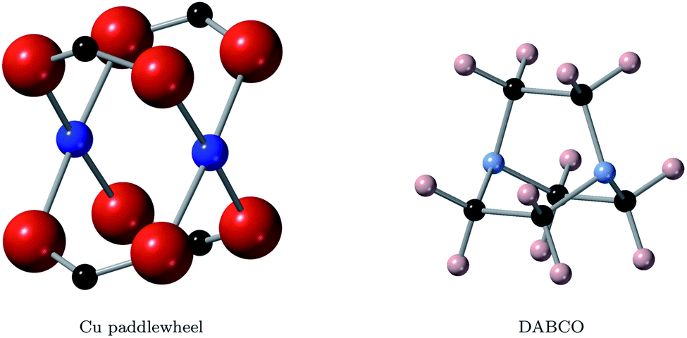 | ||
| Fig. 1 Structures of the two important building blocks of this study, the copper paddle wheel (left) and the DABCO ligand (right). Blue, red, black, azure and peach spheres represent copper, oxygen, carbon, nitrogen and hydrogen atoms. | ||
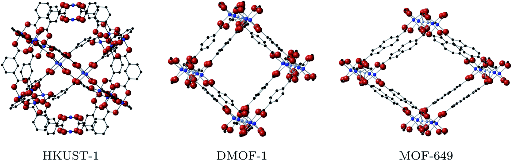 | ||
| Fig. 2 Structures of the Cu-based MOFs that contain the paddlewheel motif: HKUST-1 (left), DMOF-1 (centre) and MOF-649 (right). Hydrogen atoms are omitted for visibility here and in all following figures. | ||
DMOF-1 contains a bi-ligand motif formed of 1,4-diazabicyclo[2.2.2]octane (DABCO) ligands along c-direction of the crystal and benzenedicarboxylate (BDC) ligands in a-/b-direction, connected by copper paddle wheel nodes (see Fig. 2, middle). MOF-649 has the same topology, but instead of BDC ligands in a-/b-direction it consists of 2,6-azulenedicarboxylate (AZDC) ligands (see Fig. 2 on the right). It was originally reported with a Zn2+ paddle wheel node, but given the similarities in topology between MOF-649 and DMOF-1 we consider it appropriate to substitute the Zn atoms for Cu for comparison of the electronic structure of the two systems. DABCO is a di-nitrogen containing, anti-aromatic ligand commonly used as a complexing ligand. The availability of the lone pair on the nitrogen allows for facile donation and subsequent coordination to metal centres. This direct coordination of metal atom and ligand lone pair could lead to an intrinsic charge pathway similar to the extrinsic pathways created in HKUST-1 upon TCNQ incorporation.
In this study, we analyse the electronic structure of DMOF-1 and MOF-649 with paddle wheel topology based on Cu connected to DABCO, focusing on the alignment of the frontier orbitals of the building blocks. First-principles properties such as band structure and effective mass are reported for both systems based on density-functional theory (DFT). We provide an explanation of the resulting crystal orbitals based on the alignment and mixing of the original molecular orbitals of the building blocks. Finally, we demonstrate the effect of substitutions on the band structure of MOF-649.
2 Methodology
All electronic structure calculations were performed with density functional theory (DFT) using the all-electron FHI-Aims package.25–29 The MOF structures were first relaxed under periodic boundary conditions with the Tier 1 numerical basis set using the semilocal PBEsol functional, and subsequently relaxed with the Tier 2 basis set and the same functional. Convergence criteria were set such as to achieve forces of less than 0.01 eV per Å per atom. We used a 1 × 1 × 2 supercell for all DMOF-1 and MOF-649 calculations. Electronic structure calculations that followed were done with the hybrid functional HSE06 with 25% Hartree–Fock exchange for greater accuracy.Band structure calculations were performed in two separate runs, using a 1 × 1 × 8 k-grid for calculations of the bands in c-direction and a 8 × 1 × 1 k-grid in a-/b-direction; due to the computational cost of a hybrid band structure calculation. A single calculation on an equally fine k-grid (e.g. 8 × 1 × 8) would not have been feasible. The accompanying partial density of states were plotted with a Gaussian broadening of 0.05 eV. Effective masses were calculated with the code effmass,30 which we updated in this work for compatibility with FHI-Aims. The conventional definition of the effective mass
In MOFs however, most bands are far from parabolic, and thus the definition of the effective mass must be changed to account for the non-quadratic curvature of the band.31 In the effmass implementation, this can be done by either considering higher order energy terms in the dispersion relation (transport effective mass) or by taking into account the occupation of all bands as determined by the Fermi–Dirac distribution (optical effective mass). In our calculations, we assumed the Fermi level to be at the top of the valence band and calculated the optical effective mass at T = 300 K.
To explain the orbital composition of the bands near the highest occupied crystal orbital (HOCO) and lowest occupied crystal orbital (LUCO), we performed neutral cluster calculations of a single copper acetate and two DABCO ligands, decreasing the distance of copper and nitrogen from 6 Å to 2.5 Å. The calculations done to evaluate the energy alignment of the building blocks were done as cluster calculations as well. In cluster calculations, we relaxed all structures on hybrid functional level immediately before performing electronic structure calculations. All orbitals are presented with an isosurface level of 0.015 within VESTA.32
3 Results & discussion
3.1 DMOF-1
DMOF-1 consists of Cu, Ni or Zn paddle-wheel nodes connected by BDC ligands in the a-/b-direction and DABCO ligands in the c-direction.33 DMOF-1 has been mainly studied because of structural changes upon post modification of the BDC ligand including ‘breathing’ effects and structural compression with polar adsorbate concentration.34 To our knowledge, no conductivity studies on DMOF-1 have been reported so far.DMOF-1 with a Cu node in its ground state square-pore structure contains Cu2+/d1 cations in antiferromagnetic (AFM) alignment.35 It has orthorhombic symmetry, belonging to the space group P4/mmm. Firstly, the ground state of DMOF-1 was confirmed to be AFM within the Cu(II) paddle wheels, being 78 meV per paddle-wheel more stable than ferromagnetic (FM) ordering using the PBEsol functional. This is in agreement with calculated ground state magnetic ordering in structurally similar Cu paddle wheel MOFs.36
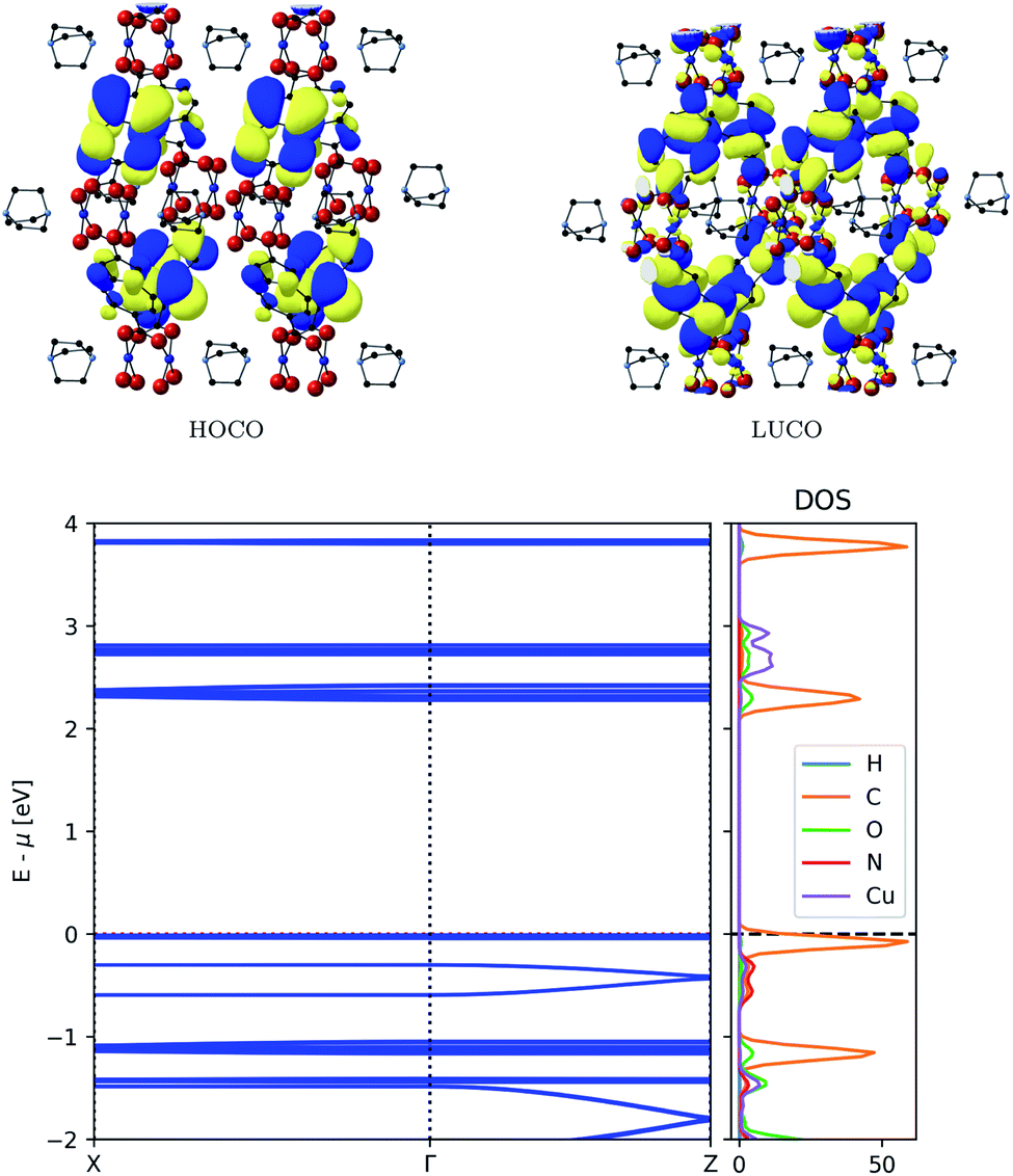
The resulting frontier orbitals from electronic structure calculations with HSE06 are shown in the top of Fig. 3. They show a possible conduction pathway along c-direction in the valence band due to the delocalised electron density. The main reason for this is a sizeable overlap of Cu-d2 orbitals with DABCO nitrogen lone pairs. This assignment is confirmed by the dispersion observed in the conduction band, as seen in the bottom of Fig. 3, which implies a smaller carrier effective mass than usual in MOFs.
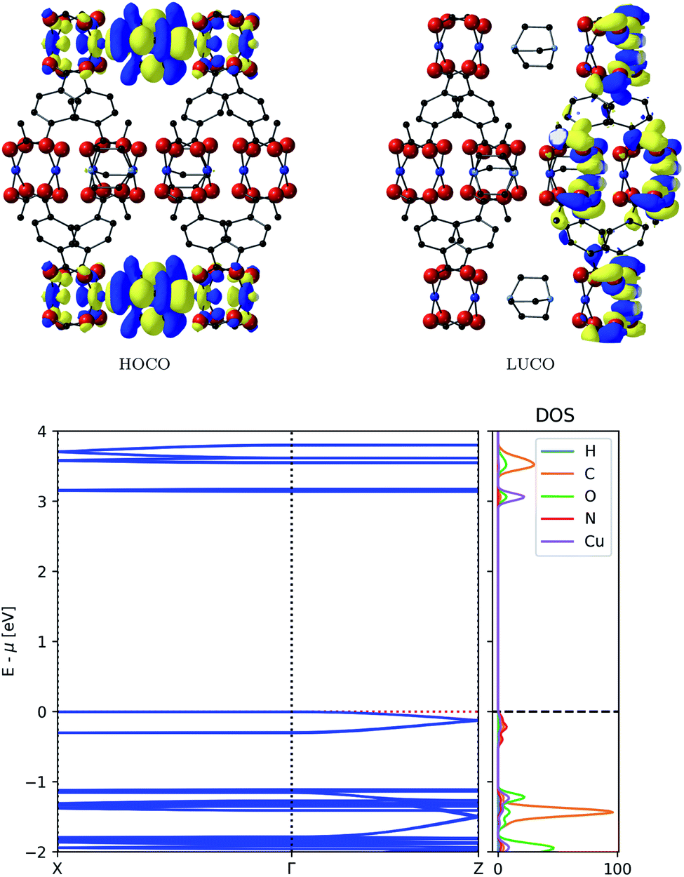 | ||
| Fig. 3 Top: Frontier orbitals of DMOF-1. Bottom: Electronic band structure (left) and atom-projected density of states (right) of DMOF-1. | ||
The partial density of states in Fig. 3 supports our assumption of the orbital composition, revealing that the valence band is mostly made of N orbitals and smaller contribution of Cu orbitals. This infers that the ligand is responsible for conduction pathway in the MOF, contrary to many MOFs described where conduction is promoted via the metal nodes. The energy associated with this dispersion is 0.12 eV, and the carrier effective mass is 0.81me. Compared to commercially used inorganic semiconducting materials, this dispersion might seem low; it is however higher than typical dispersions observed in MOFs.37 In contrast, the conduction band, comprised of π-orbitals on the ligand, does not enable a full pathway through the framework and shows no significant band dispersion.
3.2 MOF-649
MOF-649 was reported by Barman et al. as a framework with Zn2+ paddle wheel nodes and 2,6-azulenedicarboxylate/DABCO ligands. Azulene itself contains an intrinsic dipole and therefore has potential for increasing gas storage capacities and adsorbate interactions within a pore through additional polarisation and non-bonding forces. MOF-649 has orthorhombic symmetry and belongs to the space group Cmmm. To the best of our knowledge, no electronic structure calculations have been reported on this material.Given the similarities to DMOF-1, we calculate its properties under a substitution of Zn for Cu. Following a resolution of the magnetic ground states, a direct comparison of the electronic structure of DMOF-1 and MOF-649 can then be made. The procedure was analogous to the one used for DMOF-1: the ground state was confirmed to be AFM, 48 meV per paddle-wheel more favoured than its FM counterpart.
The band structure of MOF-649 differs significantly from that of DMOF-1 (Fig. 4, top). The conduction band is similar to DMOF-1: it consists of π-conjugated orbitals along the AZDC ligand, which does not result in a connected conduction pathway. In contrast to DMOF-1 however, the valence band exhibits orbitals located on the ligand that do not result in a connected pathway. The conjugated pathway across paddle wheel and DABCO ligand is instead found in bands below the valence band. This is confirmed by the resulting band structure (Fig. 4, bottom), which displays no dispersion in valence nor conduction band, but in the band below the former.
 | ||
| Fig. 4 Top: Frontier orbitals of MOF-649. Bottom: Electronic band structure (left) and atom-projected density of states (right) of MOF-649. | ||
The associated band width is 0.11 eV and if those states were thermally accessible, the carrier effective mass would be around 0.82me – both values comparable to those obtained for DMOF-1. The original assumptions about the orbital compositions is again confirmed by the partial density of states analysis, showing that the dispersive band originates from ligand orbitals, with a minor contribution from Cu paddle wheel orbitals.
3.3 Energy level alignment
To shed light on the band structures of the two MOFs, we performed cluster calculations of their building blocks. To do so, we calculated the electronic structure and ground state energy of a copper acetate paddlewheel (Cu2(acetate)4), DABCO, BDC and AZDC. Additionally, we studied the orbital composition of a model 1D DABCO – copper paddle wheel – DABCO rod through a series of calculations, in which we gradually decreased the distance of metal node and ligand in steps of 0.5 Å from 6 Å to 2.5 Å (the calculated approximate equilibrium distance of those two building blocks in the frameworks is 2.23 Å). The results are shown in Fig. 5 in a molecular orbital diagram. It shows that the dispersive bands which form the valence band in DMOF-1 and the band below the valence band in MOF-649 originate from the mixing of the DABCO HOMO with the originally unoccupied Cu-dz2 orbitals of the paddle wheel. Furthermore, it supports the finding that the main contribution to this band comes from ligand orbitals rather than the metal node. The diagram also resolves the non-dispersive conduction band of MOF-649, as simply being the AZDC ligand states that energetically misalign compared to the dispersive band. The additional ring fused to the benzene in AZDC provides more electron density than BDC, resulting in a HOMO of higher energy above the energy of the dispersive band.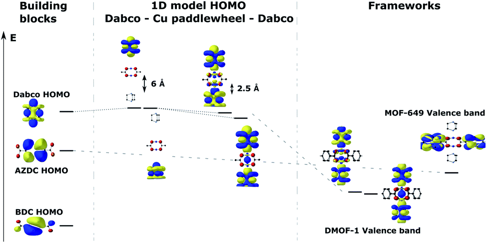 | ||
| Fig. 5 Energy (Kohn–Sham eigenvalue) alignment of the building-block molecular orbitals that combine to form the crystal orbitals in the studied frameworks. | ||
3.4 Substitution effects on the band structure of MOF-649
The unfavourable energy alignment of the AZDC linker led us to study the effect of substitution on the band structure of MOF-649. Potential substitution of hydrogen on AZDC with an electronegative group (e.g. F or Cl) could lead to a lowering of the energy of the HOMO below the dispersive state of the framework, thus turning the latter into the valence band. The resulting band structures are shown in Fig. 6.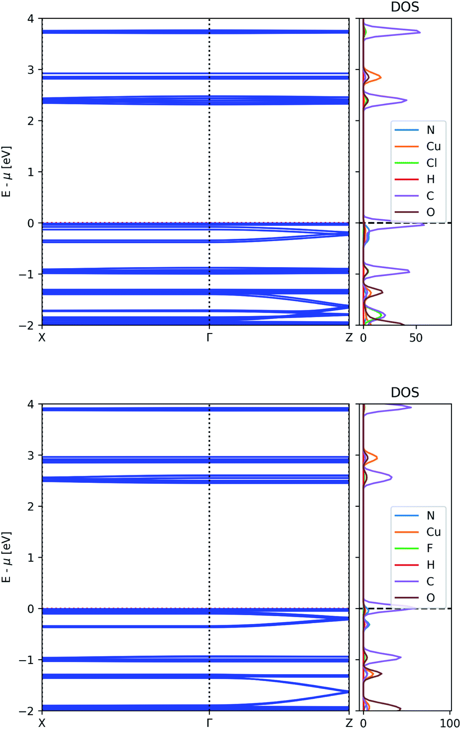 | ||
| Fig. 6 Electronic band structure and atom-projected density of states of MOF-649 with Cl (top) and F (bottom). | ||
The energy difference between the bands of interest is indeed lowered upon substitution, but neither substituent prove strong enough to invert the band positions. In the case of Cl, the dispersive band still finds itself 40 meV below the valence band, whereas in the case of F this gap shrinks to 22 meV; the difference between the top of the dispersive band to the top of the valence band remains above 60 meV however, leaving possible hole carriers thermally inaccessible.
3.5 Electronic properties
An overview of the electronic properties for DMOF-1 and the studied MOF-649 variants is given in Table 1. Each of them belong to the class of wide-bandgap semiconductors with bandgaps ranging from 2.3–3.1 eV. Since the intrinsic carrier concentrations may be low, as the bandgaps fall in the visible range of the solar spectrum there is the potential for photoconduction under illumination.| MOF | Bandgap (eV) | VB effective mass (me) |
|---|---|---|
| DMOF-1 | 3.14 | 0.81 |
| MOF-649 | 2.30 | — |
| MOF-649 w/Cl | 2.33 | — |
| MOF-649 w/F | 2.46 | — |
The effective mass of the valence bands of DMOF-1 is found to be below 1me along the direction of the DABCO ligand, suggesting increased mobility and thus increased electrical conductivity given appropriate carrier density. Other frameworks do not yield dispersive band edges, and therefore band transport is unlikely to be accessible. However, there is still the potential that localised charge transport in the form of small polarons could be accessible. To assess this would require a practical formalism for assessing polaron dynamics in hybrid frameworks, which is a target that we are working towards.
4 Conclusions
A comprehensive analysis of the electronic structure of several Cu paddle-wheel MOFs has been conducted. We found extended delocalisation of the frontier orbitals of DMOF-1. More specifically, it is the linear overlap between the copper dz2 orbitals and the DABCO lone pairs of the nitrogen that facilitates charge carrier transport in the framework. This is supported by calculated dispersion in the band structure and low effective masses of respective bands. MOF-649 shows similar band structure, but due to the different ligands the frontier orbitals do not show any dispersion. Substituting the AZDC ligand hydrogens with electronegative halogens (chlorine or fluorine) has not proven effective enough to push the ligand orbital below the dispersive bands in MOF-649. Further research could consider the effect of different pillar ligands, which may change the connectivity and topology. Our study reveals DMOF-1 as a potential semiconducting metal–organic framework.Data availability
The data that supports the findings of this study is openly available at http://doi.org/10.5281/zenodo.3768726.Conflicts of interest
There are no conflicts to declare.Acknowledgements
M. J. G. is funded by the Royal Society of Chemistry. AW is supported by a Royal Society University Research Fellowship. Via our membership of the UK's HEC Materials Chemistry Consortium, which is funded by EPSRC (EP/L000202), this work used the ARCHER UK National Supercomputing Service (http://www.archer.ac.uk). We are grateful to the UK Materials and Molecular Modelling Hub for computational resources, which is partially funded by EPSRC (EP/P020194/1).References
- O. M. Yaghi, G. Li and H. Li, Nature, 1995, 378, 703–706 CrossRef CAS.
- L. Jiao, J. Y. R. Seow, W. S. Skinner, Z. U. Wang and H.-L. Jiang, Mater. Today, 2019, 27, 43–68 CrossRef CAS.
- R. Morris and P. Wheatley, Angew. Chem., Int. Ed., 2008, 47, 4966–4981 CrossRef CAS PubMed.
- B. Wang, L.-H. Xie, X. Wang, X.-M. Liu, J. Li and J.-R. Li, Green Energy Environ., 2018, 3, 191–228 CrossRef.
- L. Wang, M. Zheng and Z. Xie, J. Mater. Chem. B, 2018, 6, 707–717 RSC.
- C. Muschielok and H. Oberhofer, J. Chem. Phys., 2019, 151, 015102 CrossRef PubMed.
- D. Sheberla, J. C. Bachman, J. S. Elias, C.-J. Sun, Y. Shao-Horn and M. Dinc, Nat. Mater., 2017, 16, 220–224 CrossRef CAS PubMed.
- L. Wang, Y. Han, X. Feng, J. Zhou, P. Qi and B. Wang, Coord. Chem. Rev., 2016, 307, 361–381 CrossRef CAS.
- Y. Ren, G. H. Chia and Z. Gao, Nano Today, 2013, 8, 577–597 CrossRef CAS.
- M. E. Ziebel, L. E. Darago and J. R. Long, J. Am. Chem. Soc., 2018, 140, 3040–3051 CrossRef CAS PubMed.
- L. Sun, M. G. Campbell and M. Dinc, Angew. Chem., Int. Ed., 2016, 55, 3566–3579 CrossRef CAS PubMed.
- J. Calbo, M. J. Golomb and A. Walsh, J. Mater. Chem. A, 2019, 7, 16571–16597 RSC.
- R. W. Day, D. K. Bediako, M. Rezaee, L. R. Parent, G. Skorupskii, M. Q. Arguilla, C. H. Hendon, I. Stassen, N. C. Gianneschi, P. Kim and M. Dinc, ACS Cent. Sci., 2019, 5, 1959–1964 CrossRef CAS PubMed.
- R. Murase, B. Ding, Q. Gu and D. M. D'Alessandro, Philos. Trans. R. Soc., A, 2019, 377, 20180226 CrossRef CAS PubMed.
- M. A. Syzgantseva, C. P. Ireland, F. M. Ebrahim, B. Smit and O. A. Syzgantseva, J. Am. Chem. Soc., 2019, 141, 6271–6278 CrossRef CAS PubMed.
- C. F. Leong, P. M. Usov and D. M. D'Alessandro, MRS Bull., 2016, 41, 858–864 CrossRef.
- E. A. Dolgopolova, V. A. Galitskiy, C. R. Martin, H. N. Gregory, B. J. Yarbrough, A. M. Rice, A. A. Berseneva, O. A. Ejegbavwo, K. S. Stephenson, P. Kittikhunnatham, S. G. Karakalos, M. D. Smith, A. Greytak, S. Garashchuk and N. B. Shustova, J. Am. Chem. Soc., 2019, 141, 5350–5358 CrossRef CAS PubMed.
- S. M. Pratik, L. Gagliardi and C. J. Cramer, J. Phys. Chem. C, 2020, 124, 1878–1887 CrossRef CAS.
- M. L. Aubrey, B. M. Wiers, S. C. Andrews, T. Sakurai, S. E. Reyes-Lillo, S. M. Hamed, C.-J. Yu, L. E. Darago, J. A. Mason and J.-O. Baeg, et al. , Nat. Mater., 2018, 17, 625–632 CrossRef CAS PubMed.
- H. C. Wentz, G. Skorupskii, A. B. Bonfim, J. L. Mancuso, C. H. Hendon, E. H. Oriel, G. T. Sazama and M. G. Campbell, Chem. Sci., 2020, 11, 1342–1346 RSC.
- A. Walsh and C. R. A. Catlow, ChemPhysChem, 2010, 11, 2341–2344 CrossRef CAS PubMed.
- A. A. Talin, A. Centrone, A. C. Ford, M. E. Foster, V. Stavila, P. Haney, R. A. Kinney, V. Szalai, F. El Gabaly, H. P. Yoon, F. Lonard and M. D. Allendorf, Science, 2014, 343, 66–69 CrossRef CAS PubMed.
- D. N. Dybtsev, H. Chun and K. Kim, Angew. Chem., Int. Ed., 2004, 43, 5033–5036 CrossRef CAS PubMed.
- S. Barman, A. Khutia, R. Koitz, O. Blacque, H. Furukawa, M. Iannuzzi, O. M. Yaghi, C. Janiak, J. Hutter and H. Berke, J. Mater. Chem. A, 2014, 2, 18823–18830 RSC.
- V. Blum, R. Gehrke, F. Hanke, P. Havu, V. Havu, X. Ren, K. Reuter and M. Scheffler, Comput. Phys. Commun., 2009, 180, 2175–2196 CrossRef CAS.
- V. Havu, V. Blum, P. Havu and M. Scheffler, J. Comput. Phys., 2009, 228, 8367–8379 CrossRef CAS.
- X. Ren, P. Rinke, V. Blum, J. Wieferink, A. Tkatchenko, A. Sanfilippo, K. Reuter and M. Scheffler, New J. Phys., 2012, 14, 053020 CrossRef.
- A. Marek, V. Blum, R. Johanni, V. Havu, B. Lang, T. Auckenthaler, A. Heinecke, H.-J. Bungartz and H. Lederer, J. Phys.: Condens. Matter, 2014, 26, 213201 CrossRef CAS PubMed.
- S. V. Levchenko, X. Ren, J. Wieferink, R. Johanni, P. Rinke, V. Blum and M. Scheffler, Comput. Phys. Commun., 2015, 192, 60–69 CrossRef CAS.
- L. D. Whalley, effmass: An effective mass package, 2018, http://joss.theoj.org/papers/10.21105/joss.00797 Search PubMed.
- L. D. Whalley, J. M. Frost, B. J. Morgan and A. Walsh, Phys. Rev. B, 2019, 99, 085207 CrossRef CAS.
- K. Momma and F. Izumi, J. Appl. Crystallogr., 2011, 44, 1272–1276 CrossRef CAS.
- K. Seki and W. Mori, J. Phys. Chem. B, 2002, 106, 1380–1385 CrossRef CAS.
- Z. Wang and S. M. Cohen, J. Am. Chem. Soc., 2009, 131, 16675–16677 CrossRef CAS PubMed.
- J. Wieme, S. M. J. Rogge, P. G. Yot, L. Vanduyfhuys, S.-K. Lee, J.-S. Chang, M. Waroquier, G. Maurin and V. Van Speybroeck, J. Mater. Chem. A, 2019, 7, 22663–22674 RSC.
- C. H. Hendon and A. Walsh, Chem. Sci., 2015, 6, 3674–3683 RSC.
- L. S. Xie, L. Sun, R. Wan, S. S. Park, J. A. DeGayner, C. H. Hendon and M. Dinc, J. Am. Chem. Soc., 2018, 140, 7411–7414 CrossRef CAS PubMed.
| This journal is © The Royal Society of Chemistry 2020 |