
 Open Access Article
 This Open Access Article is licensed under a Creative Commons Attribution-Non Commercial 3.0 Unported Licence
High-performance, long lifetime chloride ion battery using a NiFe–Cl layered double hydroxide cathode†
Qing
Yin‡
a,
Jianeng
Luo‡
a,
Jian
Zhang
a,
Lirong
Zheng
 c,
Guoqing
Cui
a,
Jingbin
Han
*a and
Dermot
O'Hare
*b
c,
Guoqing
Cui
a,
Jingbin
Han
*a and
Dermot
O'Hare
*b
aState Key Laboratory of Chemical Resource Engineering, Beijing Advanced Innovation Center for Soft Matter Science and Engineering, Beijing University of Chemical Technology, Box 98, Beijing 100029, P. R. China. E-mail: hanjb@mail.buct.edu.cn
bChemistry Research Laboratory, Department of Chemistry, University of Oxford, 12 Mansfield Road, Oxford, OX1 3TA, UK. E-mail: dermot.ohare@chem.ox.ac.uk
cInstitute of High Energy Physics, Chinese Academy of Science, Beijing 100049, P. R. China
First published on 11th June 2020
Abstract
Chloride ion batteries (CIBs) are an example of a promising new emerging rechargeable battery technology, that exhibits large theoretical volumetric energy density performance and good safety. However, unsatisfactory capacity and poor cycling lifetime of the cathode currently hinder the development of CIBs. Herein, we report the use of an Ni2+Fe3+-based layered double hydroxide (LDH) intercalated by chloride ions as a promising cathode material for CIBs. [Ni2Fe(OH)6]Cl·1.37H2O (NiFe–Cl LDH) exhibits a high maximum capacity of 350.6 mA h g−1 and a long lifetime of over 800 cycles (at 101.1 mA h g−1) at a current density of 100 mA g−1, which is superior to most currently reported CIB cathodes. In situ X-ray absorption near-edge structure (XANES) and ex situ X-ray photoelectron spectroscopy (XPS) reveal the valency changes of the Fe2+/Fe3+ and Ni2+/Ni3+ redox pairs within the metal hydroxide layers of the LDH during electrochemcial cycling. In situ XRD reveals that 2D anion diffusion within the LDH results in only ∼3% structural change. Oxygen K-edge soft X-ray absorption spectroscopy (SXAS) reveals the oxygen atoms within the MO6 octahedra reversibly participate in the electrochemical reaction. In view of the extensive chemical variation, low-cost, and ease-of-preparation of LDH-based materials we regard LDHs as a promising materials platform for application as cathode materials in chloride ion batteries.
Introduction
Over the past few decades, secondary power supplies represented by lithium-ion batteries (LIBs) have experienced revolutionary developments because of their high energy density and good cycling stability.1–3 Recently, a new type of rechargeable battery has emerged and has attracted increasing attention from both academia and industry. Unlike reversible migration of metal cations in traditional batteries, battery-based energy storage whereby anions shuttle between two electrodes, providing more options and opportunities for electrochemical energy storage.4–8 The chloride ion battery (CIB) is a representative of this kind of battery, which shows high theoretical volumetric energy density (∼2500 W h L−1), comparable with that of Li–S batteries.9,10 To date, only a few cathode materials have been reported for CIBs and most of them are metal chlorides/oxychlorides, such as CoCl2, CuCl2, FeOCl, BiOCl, and their hybrids.11–18 They normally suffer from unsatisfactory electrochemical performance and poor structural stability. Therefore, the key challenge in CIBs is to develop alternative cathode materials with competitive capacity, long cycle life and low-cost characteristics.Layered double hydroxides (LDHs) are one type of important 2D brucite-like anionic clay generally expressed as [MII1−xMIIIx(OH)2](An−)x/n·mH2O (MII and MIII are divalent and trivalent metals respectively, An− is an exchangeable anion for compensating the positive charge of the bimetal hydroxide layers).19–23 The tunability in both chemical composition and metal valency endows LDH materials with wide application potential in the fields of supercapacitors, LIBs anode materials, and electrocatalysts.24–30 In particular, LDH materials have large anion-exchange capacity with reversible anion uptake/release. Very recently, Young et al. used in situ techniques to observe the intercalation of anions into the interplanar space of an LDH under a positive bias and the de-intercalation under a reverse bias.31 Furthermore, the unique topochemical character and facile 2D diffusion pathways endow LDH materials with high structural stability and simultaneous facile anion intercalation/de-intercalation ability. In our previous work, we reported for the first time that a CoFe LDH intercalated with chloride exhibited reversible chlorination/dechlorination with a high capacity of ∼160 mA h g−1.32 However, this capacity drops off dramatically after ∼100 cycles, which probably arises as a result of local structure distortions or partial dissolution of Co from the LDH platelets.
In this work, Cl− intercalated NiFe LDH was synthesized by a simple continuous process including hydrothermal and anion-exchange steps. When used as the cathode in a CIB, the NiFe–Cl LDH shows an ultrahigh initial capacity of 350.6 mA h g−1 at a current density of 100 mA g−1. The intercalated interlamellar chloride ions reversibly shuttle between the two electrodes which is accompanied by redox reactions of both the Ni2+/Ni3+ and Fe2+/Fe3+ in the LDH layers during electrochemical cycling. The layered structure of LDH exhibits less than a 3% volume variation during chloride insertion/de-insertion, that leads to a superior cycling life (reversible capacity of 101.1 mA h g−1 after 800 cycles). In addition, a possible charge compensation mechanism involving oxygens in the MO6 octahedra in the brucite-like sheets is discussed for the first time. Owing to the hypo-toxicity and low cost of nickel and facile synthetic procedure of NiFe–Cl LDH, these encouraging results present a range of opportunities for LDHs as a material platform for anion insertion electrochemistry and an exciting new frontier for the development of novel anion-based rechargeable batteries and large-scale energy-storage systems.
Results and discussion
Synthesis and characterization
NiFe–Cl nanoplatelets were prepared by a facile two-step process: preparation of NiFe–CO3 LDH precursor via hydrothermal method followed by ion-exchange of the interlayer CO32− by Cl− ions. X-ray diffraction (XRD) pattern (Fig. S1, ESI†) of the NiFe–CO3 LDH sample with Ni/Fe ratio of 2/1 indicates a well-defined carbonate-intercalated LDH with a basal plane spacing of ∼7.42 Å.33 After ion-exchange, all Bragg reflections in the XRD pattern can be indexed to a rhombohedral unit cell, reflections indexed as (003), (006), (110), and (113) were observed at 2θ = 11.54°, 23.22°, 59.80°, and 61.14° respectively. The XRD showed no evidence for the presence of any crystalline impurity phases. The interlayer spacing of the NiFe–Cl LDH expands to 7.67 Å (Δ = 0.25 Å; 3%), to accommodate the Cl− anions between the layers (inset of Fig. 1a).34 Fourier transform infrared spectroscopy (FTIR) has been employed to provide additional evidence for the anion exchange (Fig. S2, ESI†). We find that the intensity of the absorption band at 1380 cm−1, attributed to the ν3 mode of CO32−,35 significantly decreased in intensity after ion-exchange; (the weak feature remaining may be assigned to slight contamination from atmospheric CO2). Scanning electron microscopy (SEM) image of the as-prepared NiFe–Cl LDH (Fig. 1b) reveals a typical plate-like morphology with plates ranging in size from ∼100–200 nm, which is entirely consistent with the morphology of the NiFe–CO3 LDH precursor (Fig. S3, ESI†). The composition of the NiFe–CO3 LDH precursor and NiFe–Cl LDH are determined to be Ni2Fe(OH)6(CO3)1/2·1.56H2O and Ni2Fe(OH)6Cl·1.37H2O, respectively, based on the results of inductively coupled plasma-atomic emission spectrometer (ICP-AES) and thermogravimetry analysis (TGA) (Fig. S4, ESI†). | ||
| Fig. 1 (a) Powder XRD data of NiFe–Cl LDH (inset: structural model). (b) SEM image of the as-prepared NiFe–Cl LDH sample. XPS spectra of (c) Ni 2p, (d) Fe 2p and (e) O 1s for NiFe–Cl LDH. | ||
Fig. 1c–e shows the Ni 2p, Fe 2p and O 1s X-ray photoelectron spectroscopy (XPS) spectra of the NiFe–Cl LDH. The binding energies for the Ni 2p electrons (Fig. 1c) are similar to those of Ni2+ with Ni 2p3/2 and 2p1/2 peak located at 854.79 and 872.74 eV, respectively.36 For Fe, two photoemissions are observed at 711.82 eV (Fe 2p3/2) and 725.02 eV (Fe 2p1/2) (Fig. 1d), indicating the presence of Fe3+.37Fig. 1e presents that three different photoemission components in the O 1s region. The binding energies at 529.65 eV (O1) and 531.39 eV (O2) are assigned to the metal–oxygen (M–O) bonds and O–H bonds in LDH, respectively; the low intensity photoemission feature at 533.1 eV (O3) may be ascribed to adsorbed O–O bonds from molecular oxygen.38
Electrochemical performance
The electrochemical characteristics of the NiFe–Cl LDH cathode were carried out in a Li/Bpy1,4Cl–PC/NiFe–Cl LDH CIB system, using metallic Li as the anode and 0.5 M 1-butyl-1-methylpyrrolidinium chloride (Bpy1,4Cl) in propylene carbonate (PC) as electrolyte. To optimize the Ni/Fe ratio to achieve the best energy storage performance, different NixFe–Cl LDH samples (x = 2, 3, 4 and 5) were synthesized (Fig. S5, ESI†) and the NiFe LDH with Ni/Fe = 2 was selected as the optimized sample (Fig. S6, ESI†). Therefore, our further study was performed using NiFe LDH sample with Ni/Fe ratio of 2. Fig. 2a displays the cyclic voltammetry (CV) profiles of the initial several cycles in a voltage range of 1.2–3.0 V (vs. Li/Li+) with a scan rate of 0.2 mV−1. The battery was firstly discharged to 1.2 V (vs. Li/Li+) from open circuit voltage. Two pairs of broad redox events at 2.12/2.45 V and 1.93/1.55 V were observed. These current–voltage profiles maintain a similar shape during the subsequent cycles except for an apparent polarization during the first discharging process. The broad redox feature is caused by either multi-step reaction processes or multi-element redox reactions during the charge–discharge (discussed later). Galvanostatic discharge/charge curves (Fig. 2b) at different current densities show simple sloping profiles without an obvious plateau, suggesting that the NiFe–Cl LDH cathode undergoes no significant structural phase transformations but only anion intercalation/de-intercalation. Maximum discharge capacities of 350.1, 140.9 and 87.5 mA h g−1 were obtained at 100, 250 and 500 mA g−1, respectively.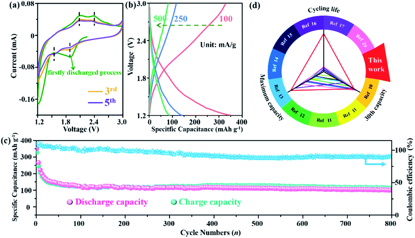 | ||
| Fig. 2 Electrochemical performance of the NiFe–Cl LDH based CIB. (a) CV curves at a scan rate of 0.2 mV s−1. (b) Galvanostatic discharge/charge curves (current density: 100 mA g−1) at a voltage range from 1.2–3.0 V. (c) Cycle performances and corresponding coulombic efficiency at a current density of 100 mA g−1 within 800 cycles. (d) Discharge specific capacity and cycling life of NiFe–Cl LDH material compared with other reported cathodes of CIBs. | ||
The cycling stability of the NiFe–Cl LDH electrode operated at a current density of 100 mA g−1 is shown in Fig. 2c. Surprisingly, a high discharge specific capacity of 101.1 mA h g−1 was obtained after 800 cycles with a coulombic efficiency of 90.3%, which demonstrated that the cell is capable of delivering outstanding cycling stability. Some inevitable side reactions involving either the solvent and/or electrolyte resulted in coulombic efficiencies of more than 100% in the initial cycles. The slowly decreasing coulombic efficiency may be due to the gradual accumulation of non-conducting LiCl on the anode or side reactions involving electrolyte decomposition during cycling. For comparison, the specific capacity and cyclic stability data of other CIB cathode materials reported works to date are summarized in Fig. 2d and Table S1.† To the best of our knowledge, the NiFe–Cl LDH outperforms most of the previously reported CIB cathodes,11–18,32 exhibiting superior Cl− storage capability.
Evolution of structure and composition
In order to probe the evolution of the host structure and Cl− storage mechanism for NiFe–Cl LDH, an in situ XRD study of the cathode was performed during a whole charge/discharge process at a constant rate of 50 mA g−1 (Fig. 3a). No new phases except the start and final LDHs were detected during the electrochemical process (Fig. 3b), this demonstrates a clean topochemical phase transformation and no electrolyte intercalation. During the charging process, the (003) Bragg reflection (Fig. 3c) exhbits a monotonic shift toward the lower 2θ values, implying that the basal spacing of NiFe–Cl LDH decreases continuously upon Cl− intercalation. In contrast, a gradual recoverly back to higher angle for the (003) Bragg reflection was observed upon discharging to 1.2 V due of de-intercalation of Cl− from NiFe–Cl LDH. Energy-dispersive X-ray spectroscopy (EDS) (Fig. S7 and S8, ESI†) analysis of the cathode material shows the accumulation and release of Cl− ions, further demonstrating the reversible shuttling of Cl− ions during the charge/discharge process. The basal spacing of the NiFe–Cl LDH expanded from 7.54 Å to 7.76 Å upon charging to 3.0 V (Fig. 3d) and then reversibly contracted to 7.55 Å when the electrode was fully discharged. | ||
| Fig. 3 (a) Typical galvanostatic charge/discharge curves. (b) In situ XRD patterns collected during the whole charge/discharge process of NiFe–Cl LDH electrode. The asterisk represents peaks from the current collector (stainless steel). (c) Partial enlargement for the diffraction of (003) plane. (d) Basal spacing (d003) of the NiFe–Cl LDH in different charge–discharge states. | ||
Investigation of Cl− storage mechanism
In situ X-ray absorption spectroscopy (XAS) data at the Fe K-edge and Ni K-edge at different charging and discharging states were recorded in order to further investigate the change in the oxidation states and local structure of NiFe–Cl LDH during the electrochemical process. Fig. 4a and b present the Fe K-edge XAS spectra compared with Fe(OH)3 as a reference. Upon charging, the Fe K-edge absorption clearly shifts toward higher energy as a function of the degree of Cl− intercalation, which reflects the change in the oxidation state of Fe. During discharge, reversible changes were observed, the Fe K-edge absorption profile completed returned to original sprectum following extraction of Cl− ions, indicating the decrease of Fe valence in the NiFe–Cl LDH cathode. In addition, the Ni2+/3+ electrochemically active redox pair also participates in the charge/discharge cycles as obserbed in the Ni K-edge spectra (Fig. 4c and d) (using Ni(OH)2 as the reference). However, unlike the spectral changes for Fe, the shift of Ni K-edge absorption is not as significant, and the intensity of the white edges shows a systematic change. We conclude that the detailed changes of the Ni ions are more complicated than the Fe centres. The evolution of the valence states of the two metals within the LDH host layer during the electrochemical process can also be highlighted by the first-order derivative of the XANES spectra (Fig. S9 and S10, ESI†).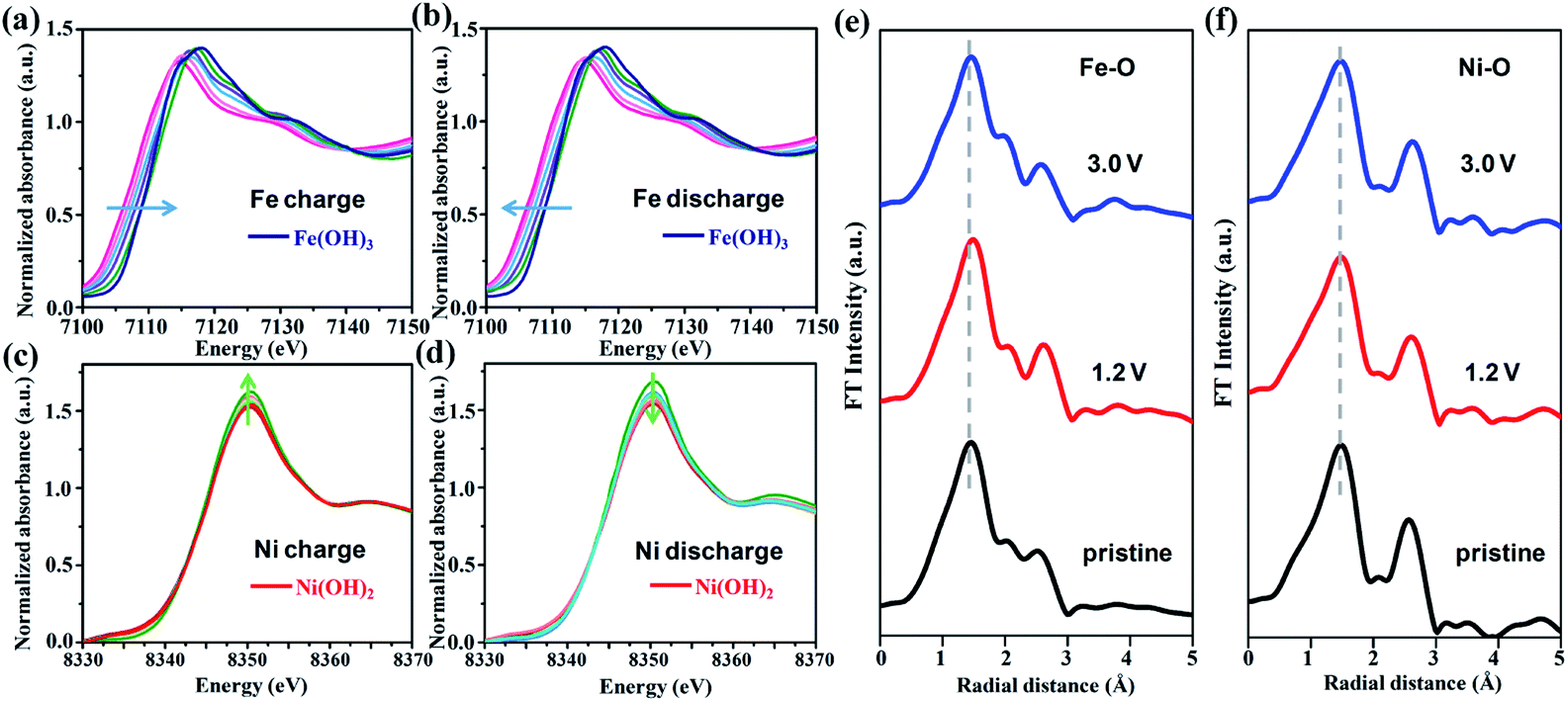 | ||
| Fig. 4 In situ XANES spectra of the Fe K-edge and Ni K-edge collected during (a), (c) charge and (b), (d) discharge process. Fourier transform magnitude of the EXAFS spectra for (e) Fe K-edge and (f) Ni K-edge collected at different charge/discharge states. | ||
The evolution of the Fe or Ni local coordination was investigated by extended X-ray absorption fine structure (EXAFS) (Fig. 4e and f). The Fourier transformation of the weighted EXAFS spectrum for both Fe and Ni K-edge under fully charged or discharged states are very similar to the pristine sample, suggesting excellent structural stability of the NiFe–Cl LDH cathode. Furthermore, we note the change in unit cell volume of the NiFe–Cl LDH cathode is less than ∼3% throughout the entire electrochemical cycle, implying a high structural reversibility which may in part account for the remarkable cycling stability of the CIB. In addition, SEM image of the NiFe–Cl LDH cathode after 800 cycles (Fig. S11, ESI†) displays that the plate-like morphology is well maintained without active material agglomeration, particle expansion or pulverization.
Although both Ni and Fe cations undergo reversible redox reactions during electrochemical cycling, they seem to have different charge compensation mechanisms and it appears that these perturb the electronic structure of the Ni atom more significantly than that of the Fe atom. To gain more insight, a series of O K-edge soft XAS were recorded over the whole electrochemical cycle. This technique is very sensitive to the electronic structure around oxygen and metal–oxygen bonding.39,40Fig. 5a shows the O K-edge spectra of NiFe–Cl LDH during the charging process. The first sharp peak around 533.5 eV corresponds to the transition of O 1s electrons to a hybridized state of the metal 3d with O 2p orbitals, while the broad higher energy peaks above 539 eV can be assigned to the transitions to hybridized states of oxygen 2p and metal 4s/4p orbitals. It was observed that upon increasing voltage, the first peak intensities decreased systematically and an additional well-resolved shoulder peak (marked by a vertical arrow) in a lower energy region at ∼532.5 eV gradually emerged. Interestingly, under the electrochemical operational conditions of the CIB, the variations in O K-edge spectra were totally reversible as shown in Fig. 5b. According to previous reports,41,42 the intensity of the pre-edge feature in the O K-edge spectra depends on the number of “d” electronic holes states in the metal 3d orbital hybridized with the O 2p orbital and the covalency of the M–O bond. These observations are consistent with Cl− intercalation giving rise to an increased effective nuclear charge of the metal cations, decreased M–O bond covalency, indicating that the oxygen ions of the MO6 octahedra in the LDH participate in the electrochemical reaction to some extent. Combined with the XANES measurements, we speculate that this kind of partial electron compensation between metal and oxygen ligand is more likely to occur in the Ni–O bonds.
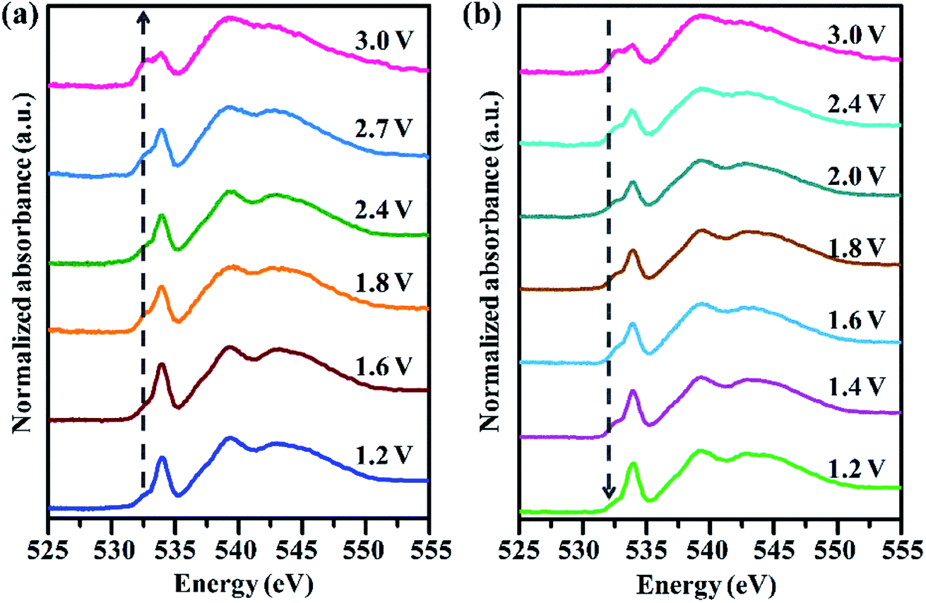 | ||
| Fig. 5 Normalized oxygen K-edge soft X-ray absorption spectra of NiFe–Cl LDH cathode in a whole electrochemical cycle: (a) charge and (b) discharge. | ||
In order to further identify the charge compensation mechanism during the electrochemically driven Cl− intercalation (deintercalation) ex situ XPS measurement was perfromed. The Fe 2p core spectra (Fig. 6a) shows Fe 2p3/2 and Fe 2p1/2 photemission feature, this feature may be deconvoluted into two pairs of resonances at 710.13/712.61 eV and 723.17/725.94 eV, that may be ascribed to the binding energies for Fe2+ and Fe3+ respectively. Upon charging, the Fe3+ signals increase at the expense of the Fe2+ signals. When charged from 1.2 to 3.0 V, the ratio of the peak integrals for Fe3+/Fe2+ increases from 0.68 to 2.26 (Fig. 6c), as a result of insertion of Cl−. During discharge, Cl− deintercalation resulted in a decrease of Fe3+/Fe2+ peak intergal ratio; when the NiFe–Cl electrode was discharged to 1.2 V, the ratio of Fe3+/Fe2+ peak intergals (∼0.63) almost fully returned to its initial value before cycling. As shown in Fig. 6b, the main Ni 2p3/2 and Ni 2p1/2 photoemission peaks were divided into two components centred at 854.82/856.73 eV and 873.12/874.59 eV, which are assigned to Ni2+ and Ni3+ respectively. The ratio of Ni3+/Ni2+ peak intergals changed from 0.56 to 1.40 (Fig. 6d) during the charging process. The XPS data reveal that the peak intergal ratio change for Ni3+/Ni2+ is smaller than that of Fe3+/Fe2+ during the electrochemical cycle. The excellent oxidation/reduction reversibility of the LDH host gives the NiFe–Cl LDH a high specific capacity as an cathode material for CIB.
 | ||
| Fig. 6 Ex situ XPS analysis on (a) Fe 2p region and (b) Ni 2p region of NiFe–Cl LDH electrode in a whole charge/discharge cycle. Relative ratio of peak integrals for (c) Fe3+/Fe2+ and (d) Ni3+/Ni2+ photoemission. | ||
In addition to the investigation on the cathode, we aslo performed an XPS analysis on the Li anode, as shown in Fig. S12 (ESI†). The binding energy of lithium metal standard appears at 54.85 eV. This peak shifts to a higher binding energy of 55.23 eV during the electrochemical cycle. This is attributed to the migration of chloride ions to the surface of Li anode, leading to the formation of LiCl. After fully charging to 3.0 V, the Li 1s peak returns to the position of 54.87 eV, demonstrating a reversible uptake/release of Cl− anions from the Li anode. Therefore, the half reaction of the anode can be described as Li + Cl  LiCl + e−.
Conclusions
We have prepared phase pure 2![[thin space (1/6-em)]](https://www.rsc.org/images/entities/char_2009.gif) :1 Ni2+:Fe3+ LDH intercalated with chloride using hydrothermal synthesis followed by anion-exchange. We have demonstrated it is a highly promising cathode material in a rechargeable CIB. Upon electrochemical cycling a high capacity cathode is observed. Our NiFe–Cl LDH containing CIB exhibits an ultralong cycle lifetime with stable reversible capacity of 101.1 mA h g−1 after 800 cycles at a current density of 100 mA g−1, which is superior to most of the currently reported CIB cathodes. The topochemical transformation characteristics plus the available interlayer 2D diffusion pathway endow NiFe–Cl LDH with high structural stability (<3% unit cell change) during facile Cl− intercalation/deintercalation. The mechanism for charge compensation during Cl− intercalation/deintercalation has been extensively studied. Reversible redox changes to the Fe and Ni cations is observed as are changes in the polarization of the Ni–O bonds during electrochemical cycling. In view of the extensive chemical variation, low-cost, and ease-of-preparation, LDH-based materials can be regarded as a promising materials platform for application in large-scale, safe energy storage devices.
:1 Ni2+:Fe3+ LDH intercalated with chloride using hydrothermal synthesis followed by anion-exchange. We have demonstrated it is a highly promising cathode material in a rechargeable CIB. Upon electrochemical cycling a high capacity cathode is observed. Our NiFe–Cl LDH containing CIB exhibits an ultralong cycle lifetime with stable reversible capacity of 101.1 mA h g−1 after 800 cycles at a current density of 100 mA g−1, which is superior to most of the currently reported CIB cathodes. The topochemical transformation characteristics plus the available interlayer 2D diffusion pathway endow NiFe–Cl LDH with high structural stability (<3% unit cell change) during facile Cl− intercalation/deintercalation. The mechanism for charge compensation during Cl− intercalation/deintercalation has been extensively studied. Reversible redox changes to the Fe and Ni cations is observed as are changes in the polarization of the Ni–O bonds during electrochemical cycling. In view of the extensive chemical variation, low-cost, and ease-of-preparation, LDH-based materials can be regarded as a promising materials platform for application in large-scale, safe energy storage devices.
Experimental section
Reagents and materials
FeCl3·6H2O, NiCl2·6H2O, NaCl, triethylamine (TEA, Sigma-Aldrich), urea and N-methyl-2-pyrrolidone (NMP) were of analytical grade and used without further purification. 1-Butyl-1-methylpyrrolidinium chloride (Bpy1,4Cl, 99%, loLiTech) and propylene carbonate (PC, anhydrous, Sigma-Aldrich) were purchased from Shanghai (China) Ailei Chemical Co. Ltd. Super P and polyvinylidene fluoride (PVDF) were obtained from Shenzhen (China) Kejing Co. Ltd.Synthesis of NiFe–CO3 LDH
TEA and urea were chosen as the chelating agent and ammonium releasing reagent during the hydrothermal process, respectively. NiCl2·6H2O, FeCl3·6H2O, and TEA were completely dissolved in 400 mL deionized water, in which the total concentration of metal cation was 20 mM, and the ratio of Ni2+/Fe3+ was 2:1. The concentration of TEA was 2.5 times that of Fe3+. Then, 7 mmol urea was added into the solution. The above mixture was stirred for 1 h and then poured into a sealed stainless-steel Teflon-lined autoclave (100 mL) at 150 °C for 48 h. The autoclave was then cooled down to room temperature and the powder NiFe–CO3 LDH sample was obtained by washing with deionized water and ethanol several times.
Preparation of NiFe–Cl LDH
Intercalation of Cl− in the NiFe–CO3 LDH precursor was conducted in a high concentration of aqueous NaCl. A flask containing 100 mL deionized water was added with 100 mg as-prepared NiFe–CO3 LDH, 0.5 mol NaCl and 41.7 μL HCl, and was then mechanically stirred under N2 atmosphere for 48 h. The NiFe–Cl LDH sample was obtained successfully after centrifuging with deionized water three times and dried at vacuum oven at 60 °C for 12 h.Electrodes preparation
The NiFe–Cl LDH was mixed with Super P and PVDF with the weight ratio of 7:2:1 in a mortar for 60 min, using NMP as the solvent. Then, the slurry was coated on the stainless-steel foil through a 100 μm blade followed by drying under vacuum oven at 110 °C for 12 h. The resulting stainless-steel foil was cut into pieces with a diameter of 12 mm and the loading mass of active materials was approximate ∼1.5 mg cm−2. The electrolyte used in our experiments was 0.5 M Bpy1,4Cl in PC solution. Glass fibre disks (Whatman) were served as the separator and the Li metal was chosen as the anode. Before the electrochemical tests, the battery had to rest for 12 h to reach the equilibrium state.
Materials characterization
X-ray diffraction (XRD) patterns of LDH samples and electrodes were recorded by a Rigaku XRD-6000 diffractometer with a scanning rate of 10° min−1, which was operated at 40 kV and 40 mA with Cu Kα radiation (λ = 0.15418 nm). The morphology of the as-prepared samples was obtained via a Zeiss Supra 55 field emission scanning electron microscope (SEM), while the composition of substance was explored by an EDX attachment (Oxford Instrument Isis 300). The Fourier transform infrared (FT-IR) spectra were acquired through a Vector 22 (Bruker) spectrophotometer with a 2 cm−1 resolution. The inductively coupled plasma (ICP) emission spectroscopy (Shimadzu ICPS-7500) was used for the metal elementary compositions of products. Thermogravimetric analyzer (TGA) was carried out on a PCT-1A thermal analysis system at an air atmosphere with a heating rate of 10 °C min−1 and a range from 25 °C to 800 °C. X-ray photoelectron spectra (XPS) were tested by a Thermo VG Escalab 250 X-ray photoelectron spectrometer at a pressure of about 2 × 10⁻⁹ Pa with Al 193 Kα X-rays as the excitation source. For the ex situ XPS measurement, the cathode was entirely charged or discharged to different states of voltage at 100 mA g−1. In order to eliminate the influence of residual electrolyte, the electrodes were washed with PC several times, preserved in a vacuum glass box to avoid the contamination of moisture and oxygen. X-ray absorption spectroscopy (XAS) measurements of Ni and Fe were carried out at beamline 1W1B while O element was measured at beamline 4W7B, all of which located on the Beijing Synchrotron Radiation Facility (BSRF), Institute of High Energy Physics (IHEP), Chinese Academy of Sciences (CAS). And the IFFEFIT 1.2.11 data analysis package (Athena, Artemis, Atoms, and FEFF6) was used for data analysis. Al foil, instead of stainless-steel foil, was used as current collector for the in situ XAS test using a home-made cell, which has a high-precision 18 mm diameter sandwich geometry and is equipped with one high-purity Be window. Cyclic voltammetry (CV) measurements were performed on a CHI 660 electrochemical workstation at different scanning rates while a Land BT2000 battery tester was used to test the cycling and charge–discharge performance at 100 mA g−1 within 1.2–3.0 V. All of the electrochemical tests were performed at 25 °C.Conflicts of interest
There are no conflicts to declare.Acknowledgements
This work was supported by the National Natural Science Foundation of China (21671015, U1707603 and 21521005) and the Fundamental Research Funds for the Central Universities (BHYC1702B, XK1802-6 and XK1803-05). We acknowledge the support from Beijing Synchrotron Radiation Facility (BSRF) for the XANES and SXAS measurements.Notes and references
- S. Kim, H. Oguchi, N. Toyama, T. Sato, S. Takagi, T. Otomo, D. Arunkumar, N. Kuwata, J. Kawamura and S. Orimo, Nat. Commun., 2019, 10, 1081–1089 CrossRef PubMed.
- M. Chen, X. Ma, B. Chen, R. Arsenault, P. Karlson, N. Simon and Y. Wang, Joule, 2019, 9, 2622–2646 CrossRef.
- J. Liu, Z. Bao, Y. Cui, E. J. Dufek, J. B. Goodenough, P. Khalifah, Q. Li, B. Y. Liaw, P. Liu, A. Manthiram, Y. S. Meng, V. R. Subramanian, M. F. Toney, V. V. Viswanathan, M. S. Whittingham, J. Xiao, W. Xu, J. Yang, X. Yang and J. Zhang, Nat. Energy, 2019, 4, 180–186 CrossRef.
- V. K. Davis, C. M. Bates, K. Omichi, B. M. Savoie, N. Momčilović, Q. Xu, W. J. Wolf, M. A. Webb, K. J. Billings, N. H. Chou, S. Alayoglu, R. K. McKenney, I. M. Darolles, N. G. Nair, A. Hightower, D. Rosenberg, M. Ahmed, C. J. Brooks, T. F. Miller, R. H. Grubbs and S. C. Jones, Science, 2018, 362, 1144–1148 CrossRef CAS PubMed.
- F. Gschwind and J. Bastien, J. Mater. Chem. A, 2015, 3, 5628–5634 RSC.
- X. Hu, F. Chen, S. Wang, Q. Ru, B. Chu, C. Wei, Y. Shi, Z. Ye, Y. Chu, X. Hou and L. Sun, ACS Appl. Mater. Interfaces, 2019, 11, 9144–9148 CrossRef CAS PubMed.
- C. Chen, T. Yu, M. Yang, X. Zhao and X. Shen, Adv. Sci., 2019, 6, 1802130 CrossRef PubMed.
- F. Chen, Z. Leong and H. Yang, Energy Storage Materials, 2017, 7, 189–194 CrossRef.
- F. Gschwind, H. Euchner and G. Rodriguez-Garcia, Eur. J. Inorg. Chem., 2017, 2784–2799 CrossRef CAS.
- X. Zhao, Z. Zhao-Karger, M. Fichtner and X. Shen, Angew. Chem., Int. Ed., 2020, 59, 5902–5949 CrossRef CAS PubMed.
- X. Zhao, S. Ren, B. Michael and M. Fichtner, J. Power Sources, 2013, 245, 706–711 CrossRef.
- X. Zhao, Z. Zhao-Karger, D. Wang and M. Fichtner, Angew. Chem., Int. Ed., 2013, 52, 13621–13624 CrossRef CAS PubMed.
- P. Gao, M. A. Reddy, X. Mu, T. Diemant, L. Zhang, Z. Z. Karger, V. S. K. Chakravadhanula, O. Clemens, R. J. Behm and M. Fichtner, Angew. Chem., Int. Ed., 2016, 55, 4285–4290 CrossRef CAS PubMed.
- X. Zhao, Z. Zhao, M. Yang, H. Xia, T. Yu and X. Shen, ACS Appl. Mater. Interfaces, 2017, 9, 2535–2540 CrossRef CAS PubMed.
- Z. Zhao, T. Yu, Y. Miao and X. Zhao, Electrochim. Acta, 2018, 270, 30–36 CrossRef CAS.
- T. Yu, Q. Li, X. Zhao, H. Xia, L. Ma, J. Wang, Y. Meng and X. Shen, ACS Energy Lett., 2017, 2, 2341–2348 CrossRef CAS.
- K. P. Lakshmi, K. J. Janas and M. M. Shaijumon, J. Power Sources, 2019, 433, 126685 CrossRef CAS.
- R. Yang, T. Yu and X. Zhao, J. Alloys Compd., 2019, 788, 407–412 CrossRef CAS.
- X. Gao, X. Liu, D. Wu, B. Qian, Z. Kou, Z. Pan, Y. Pang, L. Miao and J. Wang, Adv. Funct. Mater., 2019, 1903879 CrossRef.
- J. Liang, R. Ma, N. Iyi, Y. Ebina, K. Takada and T. Sasaki, Chem. Mater., 2010, 22, 371–378 CrossRef CAS.
- Z. Pan, Y. Jiang, P. Yang, Z. Wu, W. Tian, L. Liu, Y. Song, Q. Gu, D. Sun and L. Hu, ACS Nano, 2018, 12, 2968–2979 CrossRef CAS PubMed.
- R. Gao and D. Yan, Adv. Energy Mater., 2019, 1900954 Search PubMed.
- J. Chen, X. Wang, J. Wang and P. S. Lee, Adv. Energy Mater., 2016, 6, 1501745 CrossRef.
- X. Li, H. Wu, C. Guan, A. M. Elshahawy, Y. Dong, S. J. Pennycook and J. Wang, Small, 2018, 1803895 CrossRef PubMed.
- J. Yang, C. Yu, X. Fan and J. Qiu, Adv. Energy Mater., 2014, 4, 1400761 CrossRef.
- M. Tian, C. Liu, Z. G. Neale, J. Zheng, D. Long and G. Cao, ACS Appl. Mater. Interfaces, 2019, 11, 35977–35986 CrossRef CAS PubMed.
- L. Shi, Y. Chen, R. He, X. Chen and H. Song, Phys. Chem. Chem. Phys., 2018, 20, 16437–16443 RSC.
- G. Chen, T. Wang, J. Zhang, P. Liu, H. Sun, X. Zhuang, M. Chen and X. Feng, Adv. Mater., 2018, 30, 1706279 CrossRef PubMed.
- X. Zhang, Y. Zhao, Y. Zhao, R. Shi, G. I. N. Waterhouse and T. Zhang, Adv. Energy Mater., 2019, 9, 1900881 CrossRef.
- C. Tang, H. Wang, H. Wang, Q. Zhang, G. Tian, J. Nie and F. Wei, Adv. Mater., 2015, 27, 4516–4522 CrossRef CAS PubMed.
- M. J. Young, T. Kiryutina, N. M. Bedford, T. J. Woehl and C. U. Segre, Sci. Rep., 2019, 9, 2462–2473 CrossRef PubMed.
- Q. Yin, D. Rao, G. Zhang, Y. Zhao, J. Han, K. Lin, L. Zheng, J. Zhang, J. Zhou and M. Wei, Adv. Funct. Mater., 2019, 29, 1900983 CrossRef.
- Q. Yin, J. Luo, J. Zhang, S. Zhang, J. Han, Y. Lin, J. Zhou, L. Zheng and M. Wei, Adv. Funct. Mater., 2019, 1907448 Search PubMed.
- M. Xu and M. Wei, Adv. Funct. Mater., 2018, 28, 1802943 CrossRef.
- L. Dang, H. Liang, J. Zhuo, B. K. Lamb, H. Sheng, Y. Yang and S. Jin, Chem. Mater., 2018, 30, 4321–4330 CrossRef CAS.
- Y. Wan, W. Zhao, Y. Tang, L. Li, H. Wang, Y. Cui, J. Gu, Y. Li and J. Shi, Appl. Catal., B, 2014, 148, 114–122 CrossRef.
- S. Tiwari, R. Prakash, R. J. Choudhary and D. M. Phase, J. Phys. D: Appl. Phys., 2007, 40, 4943–4947 CrossRef CAS.
- D. Zhou, S. Wang, Y. Jia, X. Xiong, H. Yang, S. Liu, J. Tang, J. Zhang, D. Liu, L. Zheng, Y. Kuang, X. Sun and B. Liu, Angew. Chem., Int. Ed., 2019, 131, 736–740 CrossRef PubMed.
- W.-S. Yoon, K.-B. Kim, M.-G. Kim, M.-K. Lee, H.-J. Shin, J.-M. Lee, J.-S. Lee and C.-H. Yo, J. Phys. Chem. B, 2002, 106, 2526–2532 CrossRef CAS.
- B. Li and D. Xia, Adv. Mater., 2017, 29, 1701054 CrossRef PubMed.
- B. Li, H. Yan, Y. Zuo and D. Xia, Chem. Mater., 2017, 29, 2811 CrossRef CAS.
- B. Li, H. Yan, J. Ma, P. Yu, D. Xia, W. Huang, W. Chu and Z. Wu, Adv. Funct. Mater., 2014, 24, 5112–5118 CrossRef CAS.
Footnotes |
| † Electronic supplementary information (ESI) available. See DOI: 10.1039/d0ta04290k |
| ‡ These authors contributed equally to this work. |
| This journal is © The Royal Society of Chemistry 2020 |