
Bismuthene from sonoelectrochemistry as a superior anode for potassium-ion batteries†
Chao
Shen
a,
Tianle
Cheng
a,
Chunyan
Liu
a,
Lu
Huang
*a,
Mengyang
Cao
a,
Ganqiang
Song
a,
Dong
Wang
a,
Bingan
Lu
 b,
Jianwen
Wang
a,
Chichu
Qin
a,
Xingkang
Huang
c,
Ping
Peng
d,
Xilong
Li
a and
Yingpeng
Wu
*a
b,
Jianwen
Wang
a,
Chichu
Qin
a,
Xingkang
Huang
c,
Ping
Peng
d,
Xilong
Li
a and
Yingpeng
Wu
*a
aState Key Laboratory of Chem/Bio-Sensing and Chemometrics, Provincial Hunan Key Laboratory for Graphene Materials and Devices, College of Chemistry and Chemical Engineering, Hunan University, Changsha, 410082, P. R. China. E-mail: luhuang@hnu.edu.cn; wuyingpeng@hnu.edu.cn
bCollege of Physics and Electronics, Hunan University, Changsha 410082, PR China
cDepartment of Mechanical Engineering, College of Engineering & Applied Sciences, University of Wisconsin-Milwaukee, 3200 North Cramer Street, Milwaukee, WI 53211, USA
dCollege of Material and Engineering, Hunan University, Changsha 410082, PR China
First published on 29th November 2019
Abstract
Bismuth has a great potential as an anode for PIBs, due to its layered structure with a large interlayer spacing, long mean free path, high volumetric capacity (3800 mA h L−1) and environmental friendliness. Bismuthene, a 2D-layered structure, can be exfoliated from bismuth by mechanical or chemical methods. The unique structure of bismuthene is beneficial to the diffusion of potassium, penetration of the electrolyte, and buffering of the volume change along the c-axis, which will boost the anode performance of PIBs. An ultrasonication-assisted electrochemical exfoliation method was proposed in this study to prepare ultra-thin few layered bismuthene nanosheets (FBNs) simply and quickly. The as-prepared FBNs were employed in KIBs as an anode and delivered highly stable capacities of 423, 356, 275 and 227 mA h g−1 at the current densities of 2.5, 5, 10, and 15 A g−1, respectively. There was no obvious decay over 2500 cycles with a capacity of over 200 mA h g−1 at 20 A g−1, realizing excellent rate-capability and long-term cycling stability in KIBs. Furthermore, the mechanism of the excellent electrochemical performances was elucidated via in-depth characterization and theoretical calculations. This work provides a new strategy to prepare scalable ultra-thin nanosheets, which act as a promising candidate for the anode in energy storage systems.
1. Introduction
With the enormous applications in consumer electronics, hybrid electric vehicles and large-scale electric grid energy storage, tremendous interest has been directed toward the battery field.1–4 Lithium ion batteries (LIBs) dominate the current battery market, however, the high price and resource limitation drive people to look for other alternatives. Because of its high natural abundance, lower cost and similar redox potential to lithium (−2.93 V vs. −3.04 V), potassium is considered as an ideal alternative to lithium.5,6 Conventional graphite has been investigated as a potassium ion battery (KIB) anode, and provides a passable performance.7 To further improve the KIB performance, Group-VA elements (i.e., P, Sb) have been proposed as anode materials.8–12 For example, Yu et al. studied red phosphorus encapsulated in hollow carbon nanofibers as an anode for KIBs.13 Guo et al. synthesized single-crystalline metallic VSe2 nanosheets and used them as an anode for KIBs.14 Although the reported anodes achieve higher capacity than the graphite, improvements on rate capability and cycling stability are still highly desired.Bismuth, a layered rhombohedral crystal, has received steady growing interest due to its outstanding properties, including a long mean free path, high volumetric capacity (3800 mA h L−1) and environmental friendliness. More importantly, its interlayer spacing along the c-axis is 3.95 Å, which facilitates the insertion and diffusion of K-ions (1.38 Å).12,15–17 Due to the weak van der Waals forces of the bulk bismuth,18 it could be exfoliated into a 2D-layered structure, namely bismuthene, by mechanical or chemical methods. Such a thin layered structure is a promising anode with high rate capability and long-term cycling stability owing to the shorter ion diffusion length, enlarged surface for ion storage and ability to buffer the volume change along the c-axis. Efforts have been made by researchers to synthesize bismuthene,19–21 however, reported methods suffer from the drawbacks of time-consuming procedures, nonuniform thickness of the product, environmentally hazardous agents, low yield and complicated treatment of the substrate.
Recently, electrochemical exfoliation, as an important method to prepare two-dimensional materials, has been explored extensively. Ji et al. adopted electrochemical cathodic exfoliation to prepare large-area layer-tunable phosphorene which achieved excellent performance in sodium-ion batteries.22 And Li et al. selected the electrochemical exfoliation process to efficiently produce high-quality thin graphene films.23 Moreover, Duan et al. utilized the same method to synthesize highly uniform semiconducting nanosheets such as 2H–MoS2, WSe2, NbSe2 and Sb2Te3.24 However, until now, as far as we know, there is no related work yet on the external force field-assisted electrochemical exfoliation method. Herein, we report a convenient external force field-assisted electrochemical exfoliation method to prepare few-layered bismuthene nanosheets (FBNs). The unique structure of FBNs is beneficial to the diffusion of potassium, penetration of the electrolyte, and buffering of the volume change along the c-axis.15 With these features, our FBNs are explored as a KIB anode and exhibit remarkable electrochemical performances such as high capacity, excellent rate-capability and long-term cycle stability.
2. Experimental methods
2.1 Chemicals and materials
The bulk bismuth crystal (≥99.99%) was purchased from Runde Metal. Tetraheptylammonium bromide (THAB, ≥99%) and bismuth powder were purchased from Aladdin Reagent. Potassium hydroxide (KOH ≥ 99%), ethanol (EtOH, ≥99.8%), and N,N-dimethylformamide (DMF, ≥99%) were purchased from Sinopharm Chemical Reagent Co. Ltd., Shanghai, China.2.2 Preparation of FBNs
The intercalation reaction occurred in a two-electrode electrochemical system, consisting of a counter electrode (platinum) and a working electrode (bulk bismuth crystal), in a bath sonication device. The bulk bismuth crystal (10 mm in length, 5 mm in width) and the platinum piece (10 × 10 mm) were adopted as the cathode and anode, respectively. Electrolyte solution was prepared by dissolving tetraheptylammonium bromide (THAB) (250 mg) and potassium hydroxide (KOH) (10 mg) in N,N-dimethylformamide (DMF) (50 ml). For a typical process, the two-electrode system was immersed in the electrolyte solution. The voltage was applied by a DC power. The electrochemical intercalation exfoliation was performed for 8 hours. Then, the gram-scale product was collected by filtration and washing three times and dried in a vacuum oven. Parallel experiments had been done to investigate the optimum parameters, with/without ultrasound or KOH, under different operating voltages.2.3 Material characterization
SEM with EDS analyses were performed using a Hitachi FE-SEM, S4800 at 5 kV and Helios Nanolab G3 UC at 5 kV. The thickness and the topography of the bismuthene were determined using AFM (Brucker Dimension Icon Scanning Probe Microscope). Transmission electron microscopy (TEM) and high-resolution bright-field TEM were carried out using a Titan G2 60–300. Raman spectroscopy was performed on an invia-reflex with He–Ne laser light (532 nm) over the range of 50–500 cm−1. The XRD patterns were recorded on a Bruker D8 Advance diffractometer, Cu Kα1 (λ = 0.15418 nm). The BET surface area was measured by N2 adsorption–desorption isotherms with an Autosorb-1 Series Surface Area and Pore Size Analyzer (Quantachrome Instruments, Boynton Beach, FL, USA).2.4 Electrochemical measurements
Electrochemical performances were measured using CR2032 coin-type cells. The anode was fabricated by mixing the active materials, conductive agent (acetylene black), and polymer binder (polyvinylidene fluoride) with a mass ratio of 8![[thin space (1/6-em)]](https://www.rsc.org/images/entities/char_2009.gif) :1:1 in N-methyl pyrrolidinone. Then, the fully mixed slurry was uniformly pasted on copper foil and dried in a vacuum oven overnight at 80 °C. The mass loading of the active material was ∼1 mg cm−2.25–27 Potassium foil was utilized as the counter electrode and 1 M KPF6 in DME was used as the electrolyte in the half cells. Whatman GF/D glass fiber paper was utilized as the separator. All cells were assembled in a glovebox (MIKROUNA, UNI.) filled with argon, and the content of water and oxygen was below 0.1 ppm. Galvanostatic discharge–charge measurements were conducted using a battery test system (Land CT2001A) with a cutoff voltage ranging between 0.01 and 3.00 V at different current densities. CV curves were recorded using an electrochemical workstation (IVIUM-VERTEX. C, Netherlands) at a scan rate of 0.1 mV s−1. Electrochemical impedance spectrometry analysis was carried out on the same electrochemical workstation in a frequency range of 0.01–100 kHz.
:1:1 in N-methyl pyrrolidinone. Then, the fully mixed slurry was uniformly pasted on copper foil and dried in a vacuum oven overnight at 80 °C. The mass loading of the active material was ∼1 mg cm−2.25–27 Potassium foil was utilized as the counter electrode and 1 M KPF6 in DME was used as the electrolyte in the half cells. Whatman GF/D glass fiber paper was utilized as the separator. All cells were assembled in a glovebox (MIKROUNA, UNI.) filled with argon, and the content of water and oxygen was below 0.1 ppm. Galvanostatic discharge–charge measurements were conducted using a battery test system (Land CT2001A) with a cutoff voltage ranging between 0.01 and 3.00 V at different current densities. CV curves were recorded using an electrochemical workstation (IVIUM-VERTEX. C, Netherlands) at a scan rate of 0.1 mV s−1. Electrochemical impedance spectrometry analysis was carried out on the same electrochemical workstation in a frequency range of 0.01–100 kHz.
2.5 Density functional theory (DFT) calculations
The density functional theory calculations were implemented based on the Perdew–Burke–Ernzerhof functional and DND basis set in the DMol3 package.28 The 4 × 4 three-layer supercell consisting of 96 Bi atoms was constructed to describe the multi-layer Bi model. A 15 Å vacuum layer was used to avoid the interaction. The Brillouin zone was sampled with a 5 × 5 × 1 Monkhorst–Pack k-point mesh. The convergence criteria for the self-consistent field and the geometry optimization were set to be 2.0 × 10⁻⁵ and 2.0 × 10⁻⁵ hartree, respectively. The LST/QST method was chosen for the transition state search.3. Results and discussion
The preparation of FBNs was performed with a two-electrode electrochemical system (Fig. 1a). The process of electrochemical cathodic exfoliation was carried out as illustrated in Fig. 1b and is detailed in the experimental section. In the initial process of electrochemical exfoliation, the tetraheptylammonium cations (THA+) were inserted into the bulk bismuth layers. Meanwhile, ultrasonication was applied as an external force field to improve the productivity. With the assistance of ultrasonication, an external shear force was applied on the THA+ intercalated compound and FBNs were rapidly peeled off from the bulk bismuth and then dispersed into the electrolyte.29 During this process, the electrolyte around the bulk bismuth crystal turned dark, indicating the peeling of the bismuthene. Both KOH and the sonication played key roles in the whole exfoliation process. KOH provided a larger zeta potential (over 30 mV) which was beneficial to prevent the FBN re-aggregation and stacking.24 In the meantime, the sonication not only provided sufficient agitation to keep the layers further away from each other, but also increased the exfoliation yield by improving the cation migration rate.29 After 8 hour exfoliation, the FBNs were collected after washing and drying. To investigate the optimum parameters, the effects of the operating voltage, ultrasonication and KOH were explored (Table S1†). The obtained products are shown in Fig. S1.† It is worth noting that the morphologies of the FBNs changed by the different operating voltages from 5 to 20 V. As we can see, Fig. S1-c1† shows the best thin layered morphology, and we chose 15 V as the optimal operating voltage in the following experiments.30 | ||
| Fig. 1 (a and b) Schematic illustration of FBN production through the electrochemical exfoliation approach; (c and d) SEM image and the corresponding EDS map of FBNs; (e) AFM image of FBNs. | ||
As shown in Fig. 1c, S2 and S3,† FBNs from the optimized conditions with the layered structure were obtained after the electrochemical exfoliation. To obtain a better view of the structure of our FBNs, TEM and AFM are adopted to characterize the morphology and the quality of the FBNs, as shown in Fig. 1e and 2a. Those FBNs, similar to graphene, were curved and wrinkled with a high surface area-to-volume of 176.4 m2 cm−3 (Fig. S4†), presumably due to their extremely thin thickness and the soft nature of metallic Bi. Fig. 1d depicts the elemental analysis result by energy dispersive X-ray spectroscopy (EDS) and indicates that these nanosheets were mainly composed of the Bi element which was in agreement with the XPS result (Fig. S5 and S6†). The spectra of Bi are consistent between the FBNs and bismuth powder. To further investigate the morphologies and microstructures of the FBNs, atomic force microscopy (AFM) and transmission electron microscopy (TEM) tests were performed. The AFM image in Fig. 1e clearly shows that the lateral dimension of our FBNs is around 500 nm. Meanwhile, the topographical profiles in Fig. 1e and S7† illustrate that the thickness of the FBNs is around 1.3 nm, which suggests that the FBNs are dominantly constructed by two bismuthene layers.31 Such ultrathin FBNs can alleviate the large volume expansion during the alloying reaction and shorten the diffusion length of potassium ions and electrons, which are beneficial to potassium storage performance. Moreover, from the TEM image in Fig. 2a, we can see that the FBNs have a transparent folded film-like structure with an average lateral size of about 500 nm, which is consistent with the AFM result. The high-resolution TEM (HRTEM) image (Fig. 2b) suggests a lattice spacing of 0.328 nm, corresponding to the distance of the (012) planes of the rhombohedral Bi crystal. And the Fig. 2b inset shows the corresponding fast Fourier transform (FFT) pattern of FBNs, indicating the excellent crystallinity of the FBNs.12 The high crystallinity can be attributed to the reductive potential during the electrochemical exfoliation, which avoided introducing a large amount of oxidation-induced defects into the FBNs.32 The chemical map extracted from the TEM image (Fig. 2c) shows that the whole nanosheets are composed of the Bi element, which is in good agreement with the SEM results. In a further step, X-ray diffraction (XRD) measurements were conducted to examine the quality of the obtained FBNs. As shown in Fig. 2d, all diffraction peaks in the XRD pattern of the FBNs match well with the initial bulk Bi crystals. It is worth noting that the corresponding full-width at half-maximum (FWHM) of the (012) peak of FBNs broadened compared to the bulk bismuth crystal, confirming the structural expansion between bismuthene layers along the c-axis and the decrease of the stacking layer number.20,33,34 Meanwhile, the bulk Bi crystal and the FBNs were characterized by Raman spectra (Fig. 2e). Both Bi and FBNs show two characteristic peaks around 71 cm−1 and 98 cm−1, which can be assigned to the Eg and A1g vibration modes of Bismuth. This Raman result proved that the product by the exfoliation method was constructed by elemental Bi. What's more, the FBNs showed a decrease of I(Eg)/I(A1g), which could be attributed to the phonon confinement effect due to the lowered dimension from 3D bulk to 2D nanosheets. And the broadened peaks of FBNs were caused by the size decrease of the bismuth crystal which can be explained by the retarded Green's function.35
 | ||
| Fig. 2 (a) Low-magnification TEM image of FBNs; (b) HRTEM image and (inset) the corresponding FFT pattern of FBNs; (c) chemical map of FBNs; (d and e) XRD pattern and Raman spectrum of FBNs, respectively. | ||
Electrochemical properties of the FBN anode were evaluated using the half cell with metallic K foil as the counter electrode. Benefitting from the micrometer-scale lateral dimension and plentiful buffering space along the c-axis, the kinetic process of the K-ion insertion/extraction at the FBNs is promoted, and the integrity of the electrode structure can be well maintained during the K-ion insertion and extraction process.36 As shown in Fig. 3a, the FBN anode exhibits an excellent electrochemical cycling stability at an ultra-large current density of 20 A g−1. The coulombic efficiency can reach near 100% after the initial cycles and the specific capacity can remain above 200 mA h g−1 even after 2500 cycles, suggesting the highly reversible K-ion insertion/extraction process, which is a notably outstanding result of the as-reported KIB anode (Fig. 4).9,12,37–43 A stable electrode is presented after long cycles (Fig. S9†). Fig. 3b presents an excellent rate performance resulting from the laminated structure. The electrode delivers highly stable capacities of 423, 356, 275, 227 and 182 mA h g−1 at the current densities of 2.5, 5, 10, 15, and 20 A g−1, respectively. Moreover, when the current density returns to 5 A g−1 after cycling at different current densities for more than 100 cycles, the specific capacity can be recovered to 312 mA h g−1, indicating the excellent structural stability of the FBNs under different charge/discharge processes. The corresponding charge–discharge curves display similar potential profiles even at ultrahigh rates (Fig. 3c). Additionally, under the current density of 7.5 A g−1, the charge specific capacity remains at 318 mA h g−1 after 100 cycles with 90.5% capacity retention (Fig. 3d). The performance at relatively low current density is also good as shown in Fig. S8.† For comparison, bismuth powder (exfoliated from bulk bismuth and having a size of about 5 μm) was used as the anode and the electrochemical performance is exhibited in Fig. 3e. The bismuth powder delivered a reversible capacity of 474 mA h g−1 at the current density of 7.5 A g−1 in the initial cycles, however, the capacity decreases to 194 after 100 cycles.
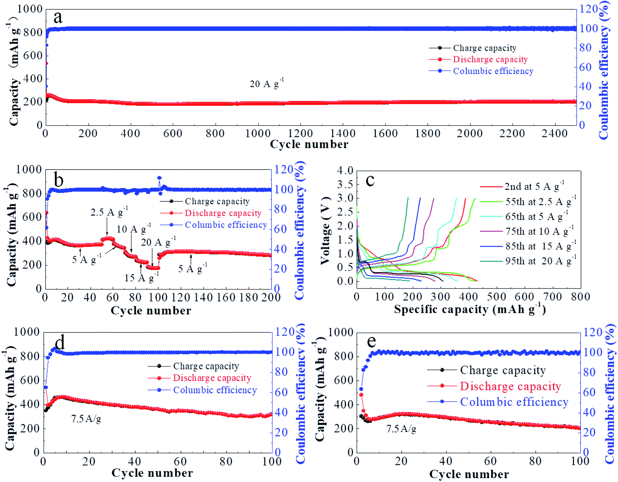 | ||
| Fig. 3 Electrochemical characterization of FBNs for KIBs in 1 M KPF6 in a DME-based electrolyte; (a) long-term cycling performance at a current density of 20 A g−1 for 2500 cycles; (b) rate performance of FBNs at different current densities; (c) galvanostatic charge and discharge curves of FBNs at different densities from 2.5 to 20 A g−1; (d) cycling performance at a current density of 7.5 A g−1 for 100 cycles; (e) cycling performance of bismuth powder. | ||
 | ||
| Fig. 4 A comparison of cycling performance with as-reported KIB anodes. | ||
The inset of Fig. 5a is the schematic illustration of the K-ion storage behavior in Bi, including three stages of gradual phase reactions (Bi ⇌ KBi2 ⇌ K3Bi2 ⇌ K3Bi).17 From Fig. S10,† the three stages of phase reactions were detected clearly by Operando XRD measurements. To further understand the reaction mechanisms of our FBNs, cyclic voltammetry (CV) measurements were carried out at the scan rate of 0.1 mV s−1 in a voltage range of 0.01–3 V (versus K+/K). During the first cathodic scan, the irreversible broad peak around 1 V is attributed to the formation of a solid electrolyte interface (SEI).14 The other irreversible peaks at 1.87 and 2.61 V are caused by the oxygen groups, and disappear after a few cycles, indicating that the impurities like bismuth oxide on the electrochemical behaviors were negligible. Fig. 5a shows the redox peaks located at 0.91/1.16, 0.45/0.68 and 0.30/0.55 V, corresponding to the K-ion insertion and extraction behaviors.44 Besides, the CV curves at various scan rates (from 0.5 to 10 mV s−1) were investigated to understand the high-rate capabilities of the FBN electrode and the kinetic process. The obtained peak current (i, mA) and scan rate (ν, mV s−1) obey the following power-law relationship: i = aνb, where a and b are two adjustable parameters, and their values can be calculated from the slope by plotting the data of log i versus logν. (detailed in Fig. S11†) The b-value of 0.5 represents a diffusion-controlled redox reaction, whereas the value of 1 indicates a surface-controlled reaction. As displayed in Fig. 5a and b, the calculated b-values of a typical pair of cathodic peak (R3) and anodic peak (O3) of the battery are 0.759 and 0.795, respectively, indicating a synergistic control mechanism.45
 | ||
| Fig. 5 (a) Cyclic voltammetry of FBNs at 0.1 mV s−1 and the inserted picture displays potassiation–depotassiation processes at the FBN electrode, the green spheres are bismuth atoms and the pink spheres are potassium atoms; (b) CV curves at different scan rates; (c) Nyquist plots of FBNs and bismuth powder and the corresponding fitted curves; (d) schematic of the free bismuthene monolayer. The hollow site, top site and valley site in one bismuthene unit cell are denoted by the blue, red, and green balls, respectively. (e) The possible ways for the migration of K atoms. The calculated diffusion barriers are marked by arrows. (f) K atom diffusion pathway (valley–hollow–valley) on the surface (on the first layer) and between the bismuthene layers (on the second layer) and K motion barrier from the valley site to the hollow site. | ||
To better understand the improved cycling and rate capability of the FBNs, density functional theory (DFT) calculations were performed to gain insight into the potassium dynamics process at FBNs. As described in Fig. 5d and e, there are several possible ways for the migration of K atoms. The calculated diffusion barriers are marked by the arrows in Fig. 5e. As demonstrated, the valley–hollow–valley route seems to be a superior route for the diffusion on the surface and between the layers, with the highest barrier of 3.1 and 12.2 kcal mol−1, respectively. For the other diffusion routes, the highest barrier is calculated to be 18.7 kcal mol−1 (valley–top route between layers), which is also a quite low level compared with the other diffusion routes.46 As a result, the K+-ion migration can work between the three sites and the valley–hollow–valley route has the most probability. The relatively low diffusion barriers of these routes offered a better rate performance of our FBNs. It should be noted that, for the top–valley and top–hollow diffusion on the surface of the FBNs, the migration is spontaneous, so we present the energy gap instead. What's more, this result indicates that K atoms are more likely to diffuse onto the surface for a lower diffusion barrier. To further investigate the kinetics of the FBN electrode, electrochemical impedance spectroscopy (EIS) was conducted and the fitted Nyquist plots are shown in Fig. 5c. In general, the low-frequency slope line presents the Warburg ion-diffusion resistance (Zw), and two high-frequency semicircles signify charge transfer (Rct) and the resistances of contact (Rf) respectively.47–49 As displayed in Tables S2 and S3,† The Rct of FBNs is 5.2 Ω and less than that of bismuth powder (222 Ω). This result indicates that the 2D structure electrode/electrolyte interface offers a superior contact and a faster K-ion transfer ability.47–49
4. Conclusion
In summary, an external force field-assisted electrochemical exfoliation method was employed to prepare uniform FBNs efficiently. The unique 2D architecture of the prepared FBNs can effectively enlarge the electrode/electrolyte contact area, promote the K-ion diffusion ability and buffer the volume change during the potassiation/depotassiation process. Owing to these multiple synergistic effects, FBNs deliver an extraordinary charge–discharge capacity of 201 mA h g−1 at the current density of 20 A g−1 for more than 2500 cycles and achieve a capacity of 423 mA h g−1 at the current density of 2.5 A g−1. Moreover, as shown in Fig. S12,† we have assembled full cells and achieved an energy density of 127 W h kg−1 with an average discharge voltage of 2.8 V. This strategy will motivate the development of 2D architecture nanoengineering. Meanwhile, these as-prepared 2D structure materials can not only offer high performance anodes for KIBs, but also be further applied in other energy storage systems and other areas such as the catalytic field.Dedication
Yingeng Wu and Lu Huang conceived the idea and directed the study. Chao Shen and Tianle Cheng prepared the FBNs. Chunyan Liu did the DFT calculation. Yingeng Wu, Chunyan Liu and Ping Peng discussed the DFT results. Bingan Lu and Chao Shen performed the operando XRD measurements. Chao Shen, Tianle Cheng, Jianwen Wang and Dong Wang performed electrochemical experiments. Chao Shen, Chichu Qin and Ganqiang Song drew the figures. Chao Shen, Yingeng Wu, Lu Huang and Xingkang Huang drafted the manuscript. Mengyang Cao, Ganqiang Song, Jianwen Wang, and Xilong Li participated in the experiments for sample preparation and characterization. All authors participated in the interpretation of the data and production of the final manuscript.Conflicts of interest
The authors declare no conflict of interest.Acknowledgements
Yingpeng Wu acknowledges financial support from the Fundamental Research Funds for the Central Universities (531107051077), National Natural Science Foundation of China (Grant No. 21805079) and Hunan high-level talent gathering project (2018RS3054). Lu Huang acknowledges financial support from the Fundamental Research Funds for the Central Universities (531107051042) and National Natural Science Foundation of China (Grant No. 21805078).Notes and references
- M. S. Whittingham, Chem. Rev., 2014, 114, 11413 CrossRef CAS PubMed.
- Y. P. Wu, L. Huang, X. K. Huang, X. R. Guo, D. Liu, D. Zheng, X. L. Zhang, R. Ren, D. Y. Qu and J. H. Chen, Energy Environ. Sci., 2017, 10, 1854–1861 RSC.
- R. Liu, C. Shen, Y. Dong, J. Qin, Q. Wang, J. Iocozzia, S. Zhao, K. Yuan, C. Han, B. Li and Z. Lin, J. Mater. Chem. A, 2018, 6, 14797–14804 RSC.
- C. Chen, X. Xie, B. Anasori, A. Sarycheva, T. Makaryan, M. Zhao, P. Urbankowski, L. Miao, J. Jiang and Y. Gogotsi, Angew. Chem., Int. Ed., 2018, 57, 1846–1850 CrossRef CAS PubMed.
- K. Beltrop, S. Beuker, A. Heckmann, M. Winter and T. Placke, Energy Environ. Sci., 2017, 10, 2090–2094 RSC.
- Y. H. Zhu, Y. B. Yin, X. Yang, T. Sun, S. Wang, Y. S. Jiang, J. M. Yan and X. B. Zhang, Angew. Chem., Int. Ed., 2017, 56, 7881–7885 CrossRef CAS PubMed.
- Z. Jian, S. Hwang, Z. Li, A. S. Hernandez, X. Wang, Z. Xing, D. Su and X. Ji, Adv. Funct. Mater., 2017, 27, 1700324–1700329 CrossRef.
- J. Zhi, S. Li, M. Han, Y. Lou and P. Chen, Adv. Energy Mater., 2018, 8, 1802254–1802264 CrossRef.
- K. Share, A. P. Cohn, R. Carter, B. Rogers and C. L. Pint, ACS Nano, 2016, 10, 9738–9744 CrossRef CAS PubMed.
- I. Sultana, M. M. Rahman, T. Ramireddy, Y. Chen and A. M. Glushenkov, J. Mater. Chem. A, 2017, 5, 23506–23512 RSC.
- Y. An, Y. Tian, L. Ci, S. Xiong, J. Feng and Y. Qian, ACS Nano, 2018, 12, 12932–12940 CrossRef CAS PubMed.
- K. Lei, C. Wang, L. Liu, Y. Luo, C. Mu, F. Li and J. Chen, Angew. Chem., Int. Ed., 2018, 57, 4687–4691 CrossRef CAS PubMed.
- Y. Wu, S. H. Hu, R. Xu, J. W. Wang, Z. Q. Peng, Q. B. Zhang and Y. Yu, Nano Lett., 2019, 19, 1351–1358 CrossRef PubMed.
- C. Yang, J. Feng, F. Lv, J. Zhou, C. Lin, K. Wang, Y. Zhang, Y. Yang, W. Wang, J. Li and S. Guo, Adv. Mater., 2018, 30, 1800036–1800043 CrossRef PubMed.
- J. Zhou, J. Chen, M. Chen, J. Wang, X. Liu, B. Wei, Z. Wang, J. Li, L. Gu, Q. Zhang, H. Wang and L. Guo, Adv. Mater., 2019, 31, 1807874–1807882 CrossRef PubMed.
- X. L. Cheng, D. J. Li, Y. Wu, R. Xu and Y. Yu, J. Mater. Chem. A, 2019, 7, 4913–4921 RSC.
- J. Q. Huang, X. Y. Lin, H. Tan and B. Zhang, Adv. Energy Mater., 2018, 8, 1703496–1703502 CrossRef.
- H. Xiao, M. Zhao, J. Zhang, X. Ma, J. Zhang, T. Hu, T. Tang, J. Jia and H. Wu, Electrochem. Commun., 2018, 8, 10–14 CrossRef.
- W. Zhang, Y. Hu, L. Ma, G. Zhu, P. Zhao, X. Xue, R. Chen, S. Yang, J. Ma, J. Liu and Z. Jin, Nano Energy, 2018, 53, 808–816 CrossRef CAS.
- N. Han, Y. Wang, H. Yang, J. Deng, J. Wu, Y. Li and Y. Li, Nat. Commun., 2018, 9, 1320–1328 CrossRef PubMed.
- N. Hussain, T. Liang, Q. Zhang, T. Anwar, Y. Huang, J. Lang, K. Huang and H. Wu, Small, 2017, 13, 1701349–1701358 CrossRef PubMed.
- Z. Huang, H. Hou, Y. Zhang, C. Wang, X. Qiu and X. Ji, Adv. Mater., 2017, 29, 1702372 CrossRef PubMed.
- C.-Y. Su, A.-Y. Lu, Y. Xu, F.-R. Chen, A. N. Khlobystov and L.-J. Li, ACS Nano, 2011, 5, 2332 CrossRef CAS PubMed.
- Z. Lin, Y. Liu, U. Halim, M. Ding, Y. Liu, Y. Wang, C. Jia, P. Chen, X. Duan, C. Wang, F. Song, M. Li, C. Wan, Y. Huang and X. Duan, Nature, 2018, 562, 254 CrossRef CAS PubMed.
- Z. Li, J. Zhang and X. W. Lou, Angew. Chem., Int. Ed., 2015, 54, 12886 CrossRef CAS PubMed.
- Y. Liu, X.-Y. Yu, Y. Fang, X. Zhu, J. Bao, X. Zhou and X. W. Lou, Joule, 2018, 2, 725 CrossRef CAS.
- W. Yang, J. Zhou, S. Wang, W. Zhang, Z. Wang, F. Lv, K. Wang, Q. Sun and S. Guo, Energy Environ. Sci., 2019, 12, 1605 RSC.
- J. P. Perdew, K. Burke and M. Ernzerhof, Phys. Rev. Lett., 1996, 78, 1396–1399 CrossRef.
- A. Ambrosi, Z. Sofer and M. Pumera, Angew. Chem., Int. Ed., 2017, 5, 10443–10445 CrossRef PubMed.
- Z. Guo, H. Zhang, S. Lu, Z. Wang, S. Tang, J. Shao, Z. Sun, H. Xie, H. Wang, X.-F. Yu and P. K. Chu, Adv. Funct. Mater., 2015, 25, 6996–7001 CrossRef CAS.
- H. You, Y. Jia, Z. Wu, F. Wang, H. Huang and Y. Wang, Nat. Commun., 2018, 9, 2889–2897 CrossRef PubMed.
- Y. Wu, M. Gong, M. C. Lin, C. Yuan, M. Angell, L. Huang, D. Y. Wang, X. Zhang, J. Yang and B. J. Hwang, Adv. Mater., 2016, 28, 9218–9222 CrossRef CAS PubMed.
- X. Mao, Y. Xu, Q. Xue, W. Wang and D. Gao, Nanoscale Res. Lett., 2013, 8, 430–436 CrossRef PubMed.
- M. Lee, A. K. Roy, S. Jo, Y. Choi, A. Chae, B. Kim, S. Y. Park and I. In, Nanotechnology, 2017, 28, 125603–125610 CrossRef PubMed.
- E. Haro-Poniatowski, M. Jouanne, J. Morhange, M. Kanehisa, R. Serna and C. N. Afonso, Phys. Rev. B: Condens. Matter Mater. Phys., 1999, 60, 10080–10086 CrossRef CAS.
- Y. Huang, C. Zhu, S. Zhang, X. Hu, K. Zhang, W. Zhou, S. Guo, F. Xu and H. Zeng, Nano Lett., 2019, 19, 1118–1123 CrossRef PubMed.
- H. Wang, X. Wu, X. Qi, W. Zhao and Z. Ju, Mater. Res. Bull., 2018, 103, 32–37 CrossRef.
- Q. Zhang, J. Mao, W. K. Pang, T. Zheng, V. Sencadas, Y. Chen, Y. Liu and Z. Guo, Adv. Energy Mater., 2018, 8, 1703288–1703297 CrossRef.
- S. Komaba, T. Hasegawa, M. Dahbi and K. Kubota, Electrochem. Commun., 2015, 60, 172–175 CrossRef CAS.
- Z. Jian, Z. Xing, C. Bommier, Z. Li and X. Ji, Adv. Energy Mater., 2016, 6, 1501874–1501878 CrossRef.
- Y. Li, R. A. Adams, A. Arora, V. G. Pol, A. M. Levine, R. J. Lee, K. Akato, A. K. Naskar and M. P. Paranthaman, J. Electrochem. Soc., 2017, 164, A1234–A1238 CrossRef CAS.
- X. Ren, Q. Zhao, W. D. McCulloch and Y. Wu, Nano Res., 2017, 10, 1313–1321 CrossRef CAS.
- H. Gao, T. F. Zhou, Y. Zheng, Q. Zhang, Y. Q. Liu, J. Chen, H. K. Liu and Z. P. Guo, Adv. Funct. Mater., 2017, 27, 1702634–1702642 CrossRef.
- R. D. Zhang, J. Z. Bao, Y. H. Wang and C. F. Sun, Chem. Sci., 2018, 9, 6193–6198 RSC.
- L. Fan, K. Lin, J. Wang, R. Ma and B. Lu, Adv. Mater., 2018, 30, 1800804–1800810 CrossRef PubMed.
- Y. Jing, Z. Zhou, C. Cabrera and Z. Chen, J. Phys. Chem. C, 2013, 117, 25409–25413 CrossRef CAS.
- J. Chang, X. Huang, G. Zhou, S. Cui, S. Mao and J. Chen, Nano Energy, 2015, 15, 679–687 CrossRef CAS.
- Y. Feng, S. Chen, J. Wang and B. Lu, J. Energy Chem., 2020, 43, 129–138 CrossRef.
- L. Wang, Q. Zhang, J. Zhu, X. Duan, Z. Xu, Y. Liu, H. Yang and B. Lu, Energy Storage Materials, 2019, 16, 37–45 CrossRef.
Footnote |
| † Electronic supplementary information (ESI) available. See DOI: 10.1039/c9ta11000c |
| This journal is © The Royal Society of Chemistry 2020 |