
 Open Access Article
 This Open Access Article is licensed under a Creative Commons Attribution-Non Commercial 3.0 Unported Licence
Microrheology imaging of fiber suspensions – a case study for lyophilized collagen I in HCl solutions
Johanna
Hafner
 *,
Claude
Oelschlaeger
and
Norbert
Willenbacher
*,
Claude
Oelschlaeger
and
Norbert
Willenbacher
Department of Mechanical Engineering and Mechanics, Applied Mechanics Group, Karlsruhe Institute of Technology, Karlsruhe, Germany. E-mail: johanna.roether@kit.edu
First published on 30th July 2020
Abstract
In fiber suspensions with low optical contrast, the in situ characterization of structural properties with conventional microscopy methods fails. However, overlaying subsequent images of multiple particle tracking (MPT) videos including short trajectories usually discarded in MPT analysis allowed for direct visualization of individual fibers and the network structure of lyophilized collagen I (Coll) distributed in hydrochloric acid solutions. MPT yielded a broad distribution of mean square displacements (MSDs). Freely diffusing tracer particles yielded viscosities indicating that, irrespective of concentration, a constant amount of Coll is dissolved in the aqueous phase. Particles found elastically trapped within fibrous Coll structures exhibited a broad range of time-independent MSDs and we propose a structure comprising multiple fiber bundles with dense regions inaccessible to tracers and elastic regions of different stiffness in between. Bulky aggregates inaccessible to the 0.2 μm tracers exist even at low Coll concentrations, a network of slender fibers evolves above the sol–gel transition and these fibers densify with increasing Coll concentration. This novel MPT-based imaging technique possesses great potential to characterize the fiber distribution in and structural properties of a broad range of biological and technical suspensions showing low contrast when imaged with conventional techniques. Thus, MPT imaging and microrheology will help to better understand the effect of fiber distribution and network structure on the viscoelastic properties of complex suspensions.
Introduction
Fiber suspensions play an important role in the processing of polymer composites, pulp and paper production and the food industry. The characteristic flow properties of fiber suspensions strongly depend on their microstructure, which is determined by the properties of dispersed fibers, i.e., their length distribution and aspect ratio, as well as hydrodynamic, thermodynamic or steric interactions among them.The bulk rheological behavior of model fiber suspensions with short, stiff fibers, such as glass, has been intensively studied theoretically1 and experimentally.2,3 Experiments focusing on hydrodynamic interaction in dilute and semi-dilute regimes yielded good agreement with available theories. For the rather short fibers, fiber orientation in shear was observed, which determined the characteristic rheological behavior of the suspensions, i.e., shear thinning.
In the concentrated regime, non-hydrodynamic particle interactions become increasingly relevant and cause a growing discrepancy between experimental results and purely hydrodynamic theories. Numerical simulations of concentrated fiber suspensions show that the stress transfer through fiber contacts can increase the viscosity of the suspension.3,4 This mechanical interplay depends on the fiber orientation and on the fiber's intrinsic properties, such as fiber elasticity, size and aspect ratio.5,6 However, numerical simulations for studying the influence of fiber elasticity on the rheological properties of the suspension deliver contradictory results, depending on the underlying geometrical model.7 A sound characterization of fiber elasticity in situ would help to answer such questions. Especially for elastic fibers with mechanical properties that are altered during drying or precipitation, in situ characterization of fiber elasticity is fundamental.
Most importantly, the flow behavior of fiber suspensions and the mechanical properties of products made thereof are determined by the size distribution and orientation of fibers in the continuous phase. Fiber localization, orientation and network structure can be studied using visualization and imaging techniques.5,8–11 In the case of glass fiber model systems, due to the difference in refractive index of the dispersed fibers and the continuous phase, visualization of suspension microstructure can be realized easily using light microscopy.8 For combinations of dispersed and continuous phases with a similar refractive index but different optical activity, e.g., cellulose and polymer fibers in organic solvents and polymer melts, the use of a polarization microscope is required.9
Alternatively, optical contrast can be created by addition of specific dyes or in suspensions with colored fibers. However, such staining protocols might alter fiber interactions and can cause flocculation. Non-transparent suspensions cannot be investigated using light microscopy at all.
NMR can help to visualize suspensions with chemically different components based on proton density, but the spatial resolution is limited.11 Electron microscopy and X-ray tomography are other widely used imaging techniques, but they require a high electron density and sufficient contrast.12,13 Furthermore, radiation damage is especially likely for biological samples and electron microscopy is not suitable for liquid products.12,14 Thus, additional processing steps, such as drying or freezing, are needed prior to the investigation of aqueous suspensions. This can result in altered fiber network properties or, in the worst case, network collapse.15
Therefore, new gentle visualization methods with enhanced contrast are required to study fiber microstructure in situ, especially for suspensions of sensitive fibers, such as DNA, proteins and other biomaterials. One prominent example of these delicate fibers is collagen I, which is a key structural protein in vertebrates. Due to its excellent biocompatibility and biodegradability,16 collagen I has diverse biomedical applications, recently as a promising bioink for 3D printing,17 and it is also a common constituent of many cosmetic and food products, partly in the processed form of gelatine. The complex hierarchical structure of collagen I includes several levels of structure (see Fig. 1). It is indisputable that the primary structure is the amino acid sequence, and the secondary and tertiary structure, referred to as α-chain, collagen I molecule or, in some cases, tropo-collagen, is a rod-like triple helix. An individual triple helix in type I collagen is <2 nm in diameter and ∼300 nm long.18–24 The quaternary structures are supra-molecular forms called collagen fibrils and collagen fibers, which are formed by self-assembly at neutral pH and an appropriate salt concentration24 of several collagen I molecules. Native collagen fibers are up to several millimeters in length and ∼10 μm in diameter.19–23 A good overview of the size estimate on different levels is provided by Varma et al.25
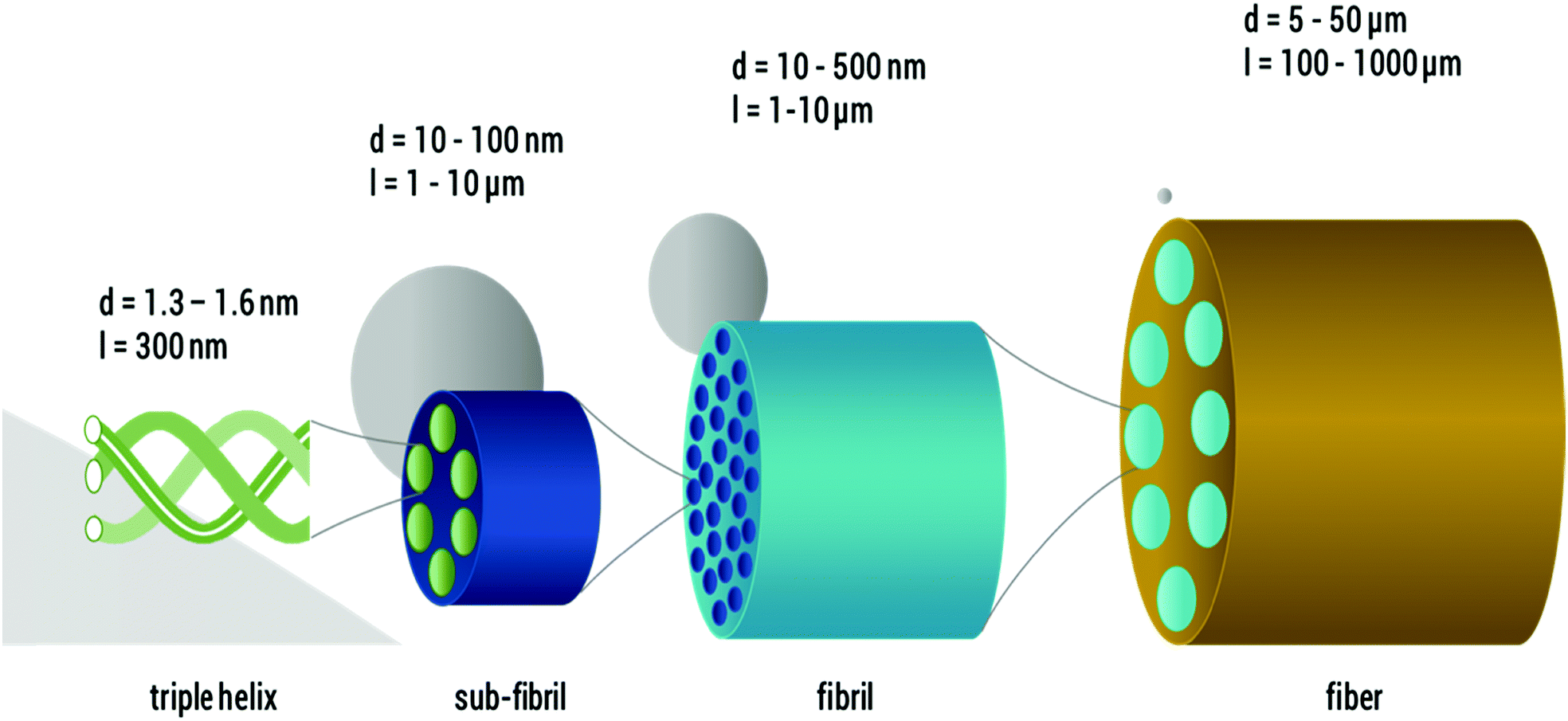 | ||
| Fig. 1 Hierarchical structure of collagen I as found in vivo (length not to scale): from left to right, single collagen I triple helices, sub-fibrils, fibrils and fibers are shown and the respective feature diameters are given. For size relation, a 100 nm particle is sketched in grey in the respective scales. | ||
An accurate characterization of the microstructural properties of collagen fiber suspensions and/or collagen networks and a better understanding of the role of fiber architecture in cellular behavior and mechanical properties are of significant importance.26,27
Many studies have characterized the macromechanical properties of collagen I solutions through rotational rheometry.28 However, for such a complex protein, interpretation of bulk rheological features in terms of structural properties is essentially impossible. Consequently, atomic force microscopy (AFM)29 was employed. A drawback of using AFM is that the sample needs to be dried prior to the measurements, which could lead to an increase of the stiffness of the collagen I structures.30 Moreover, structures may be trapped in non-equilibrium conformations when deposited on substrate surfaces. To overcome this limitation, microrheological measurements were performed using optical-tweezers to determine the viscoelastic and structural properties of collagen I solutions locally.31 A major drawback of this method for studying heterogeneities is the local measurement of the behavior of a small number of tracers that not always represents larger areas of the sample and limits statistical reliability. On the other hand, the comparably large tracer particle size (about 2 μm) used in these studies constrains the spatial resolution. However, results indicate a high degree of heterogeneity in the elasticity of the non-covalent network formed by entangled collagen I fibrils. Elasticity varies by more than one order of magnitude at different locations within the sample. Similar microheterogeneities were observed in other systems like actin filament solutions and networks,32 human or animal mucus,33–37 and cellular actin skeleton,38 and also in xanthan39 or gellan gum solutions.40 In these latter studies, the presence of such heterogeneities served as an explanation for discrepancies observed between the viscoelastic properties determined by bulk- and microrheology.
To the best of our knowledge, for lyophilized collagen I (Coll), which has achieved great technical relevance in cosmetics and pharmaceutical formulations, in HCl, no detailed comparison between data from micro- and macro-rheology measurements has been performed so far. It is only for chemically crosslinked Coll networks that such a comparison exists.41 In that latter study, local elastic moduli of Coll cryogels determined from MPT measurements were much lower than the corresponding bulk shear moduli. Analogous to earlier investigations on intermediate filament networks,42 this was attributed to a pronounced contribution of stretched, out of equilibrium chain segments between network junctions or to densely crosslinked areas not accessible to the tracer particles, thus not contributing to the MPT modulus, but showing up in the bulk modulus.
Here, we use classical bulk mechanical rheometry and, for the first time, MPT microrheology to get new insights into the structural and local viscoelastic properties of acidic lyophilized Coll suspensions in a large concentration range from 0.05 to 1 wt%. Previously, particle-tracking has been successfully used to study heterogeneous structures of fibrous porous media43 and complex heterogeneous bio-gels.44
In our MPT experiments, we use tracer particles of particularly small diameter, down to 0.2 μm, allowing for the characterization of rheological properties and, for the first time, visualization of structural properties directly inside Coll structures. Furthermore, we use the image overlay technique to obtain a direct visualization of Coll fibers and the fiber network structure and its change with concentration of suspended Coll. Additionally, we monitor the self-assembly of Coll after filtration using MPT and bulk rheological measurements. Finally, we compare the microstructure of the Coll/HCl mixtures based on lyophilized powder with that of ready-to-use native collagen I solutions at the same concentration.
Experimental
Preparation of lyophilized Coll in HCl
For the preparation of Coll suspensions, 0.05 to 1 wt% bovine collagen I (lyophilized fibrous powder from tendon, Advanced BioMatrix, USA) was dissolved in 5 mM hydrochloric acid (Carl Roth, Germany). During the freeze-drying process, inter-molecular hydrogen bonds are formed,45 which stabilize Coll aggregates, so that intensive stirring is required for reconstitution. Thus, proper reconstitution required stirring with a magnetic stirrer for 18 h at 20 °C, which finally led to highly viscous transparent liquids, which were characterized immediately. The preparation and characterization of solutions were repeated 5 times per condition to ensure appropriate reproducibility. In order to elucidate the impact of altered chemical properties after the freeze-drying and re-wetting procedure during fabrication, samples based on lyophilized Coll were compared to a commercially available solution of native collagen I from a similar origin. This was purchased from Advanced Biomatrix (FibriColTM, Bovine collagen I solution, 10 mg ml−1, Advanced BioMatrix, USA) and diluted to the respective concentrations with 5 mM hydrochloric acid, pH ∼ 2.3. This dilution experiment was done in triplicate for three separate investigations. Coomassie Brilliant Blue R250 (CBB, Merck, Germany), which exclusively stains proteins, was added for visualization of Coll using light microscopy. Additionally, in order to investigate the Coll self-assembly, all Coll fragments larger than 1.2 μm were removed by filtration. For this, we used cellulose acetate syringe filters (Puradisc FP 30, Whatman, GE Lifesciences, GB) with a pore size of 1.2 μm. Bulk shear and MPT measurements were performed prior to filtration, directly after filtration, after 7.5 h and after 24 h to monitor Coll self-assembly via the change in viscoelastic properties of the sample. This set of experiments was done in triplicate.Protein concentration was determined by BCA assay (Pierce™ BCA Protein Assay Kit, Thermo Fisher), by performing the assay in 96-well plates according to the supplier's manual. Extinction measurements were performed using an Infinite 200 (Tecan, Switzerland) plate reader.
Multiple particle tracking microrheology
The underlying idea of MPT is to study the mechanical properties of materials by monitoring the Brownian motion of inert colloidal probe particles embedded in the samples. Mason and Weitz proposed a quantitative relation between the tracer mean square displacement (MSD) 〈Δr2(τ)〉 as a function of lag time τ and the complex shear modulus of the surrounding material G* as a function of the frequency ω.46 The Laplace transform of the particle MSD 〈Δ![[r with combining tilde]](https://www.rsc.org/images/entities/i_char_0072_0303.gif) 2(iω)〉 is related to the complex modulus G* of the sample via a generalized Stokes–Einstein equation (GSE):47,48
2(iω)〉 is related to the complex modulus G* of the sample via a generalized Stokes–Einstein equation (GSE):47,48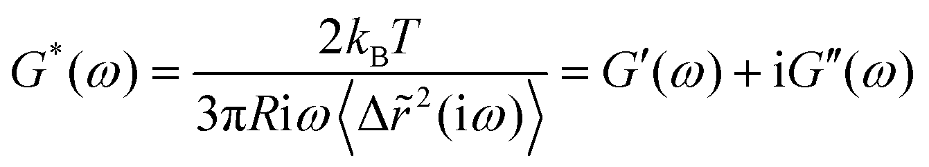 | (1) |
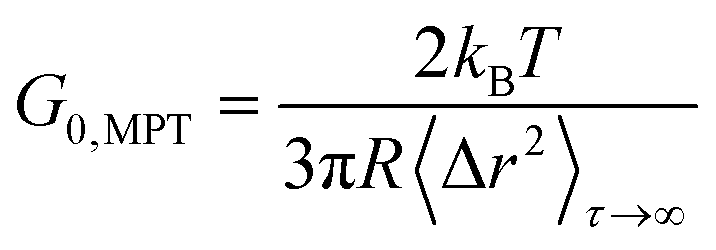
For beads suspended in an ideal elastic material with modulus G0, eqn (1) reduces to:50
 | (2) |
For ideal viscous fluids, the viscosity η is determined from the diffusivity coefficient D:46
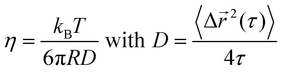 | (3) |
A detailed scheme of the MPT setup used in this study was described by Kowalczyk et al.51 It is based on an inverted fluorescence microscope (Axio Observer D1, Carl Zeiss, Germany) equipped with a Fluar 100× objective (numerical aperture 1.3, 100× magnification, oil immersion lens, Carl Zeiss). We tracked the Brownian motion of green fluorescent, non-functionalized, surfactant stabilized polystyrene microspheres of 0.2 and 0.5 μm diameter (Bangs Laboratories, USA). To evaluate collagen adsorption on the surface of the tracer particle or other specific interactions among particles and dissolved polymer, we also performed MPT measurements using polystyrene particles functionalized with polyethylene glycol (donated by Xabier Murgia, Department of Drug Delivery, Helmholtz Institute for Pharmaceutical Research Saarland). No significant difference in particle diffusion in the two tests could be found, suggesting that collagen adsorption on the particle surface is negligible here.
Two-dimensional images (field of view 127 × 127 μm, frame rate 50 frames per s, and total duration 10 s with at least 150 fluorescent beads per image) were recorded using a sCMOS camera (Zyla X, Andor Technology, Ireland, with 21.8 mm diagonal sensor size, 2160 × 2160 square pixels). The obtained movies of the fluctuating microspheres were analyzed using the software Image Processing System (iPS, Visiometrics, Germany) and a self-written Matlab code, based on the widely used Crocker and Grier tracking algorithm.52
We examined the distribution of displacements, known as the van Hove correlation function,53 and calculated the non-Gaussian parameter α:54
 | (4) |
This parameter describes the deviation of the MSD values from a Gaussian distribution expected for a homogeneous, uniform sample and characterizes the heterogeneity of the sample on a 0.1–10 μm length scale. In our study, α was determined at lag time τ = 0.1 s. In order to perform MPT measurements, tracer particles were added to the samples prior to stirring with a magnetic stirrer for 10 min to ensure a homogeneous distribution of the tracers. Liquid samples were injected into a self-built glass chamber, consisting of a cover slip and microscope glass slide with a height of ∼150 μm.
We have also determined the so-called static error χ as described by Savin et al.55 for our experimental setup. This quantity corresponds to the apparent random motion of particles due to the noise of the camera and digitization effects. It has been evaluated by fixing tracer particles on a substrate, and by performing measurements under similar noise and signal conditions as for the rest of the experiments. The static error for the experimental setup and tracer particles used here was χ = 8 × 10⁻⁵ μm2 and it defines the lower limit of accessible MSD.
Bulk rheological characterization in oscillatory shear
Oscillatory shear measurements were performed using a rotational rheometer (Physica MCR501, Anton Paar) with a plate-plate geometry (diameter 60 mm, gap 0.4 mm). Frequency sweeps, covering the frequency range from 0.01 to 10 rad s−1, were performed at a stress amplitude of σ0 = 0.5 Pa, which corresponds to the linear viscoelastic response regime for the gel samples discussed in Section 3.1. For the Coll solution in the sol-state as well as for the presumably heterogeneous filtrated samples discussed in Section 3.4, a linear viscoelastic response regime was not clearly visible, so we decided to perform all frequency sweeps at the same stress amplitude of 0.5 Pa.Results and discussion
Sol–gel transition of lyophilized Coll suspensions from bulk rheometry
Under bulk oscillatory shear (Fig. 2A), 0.05 wt% Coll suspensions appeared mainly viscous and only weak elasticity was observed. The obtained frequency sweep (black curve) shows G′ < G′′ with slopes of 2 and 1 for G′ and G′′, respectively, in the log–log representation. This behavior is typical for predominantly viscous liquids and here the viscosity was found to be close to that of water (≈3 mPa s). In contrast, all Coll suspensions with concentrations of 0.1 wt% and above showed a significant degree of elasticity with G′ > G′′ and constant moduli in the measured frequency range. This is considered to be the typical behavior of elastic, gel-like samples.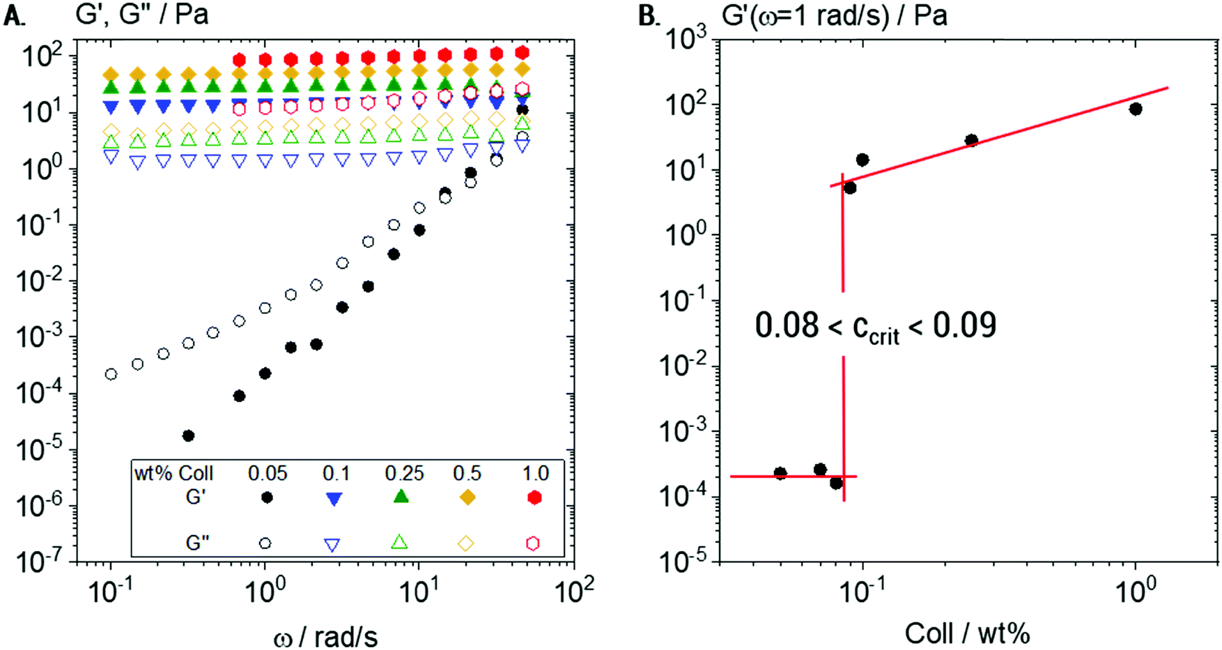 | ||
| Fig. 2 Bulk rheometry of Coll solutions: (A) variation of dynamic shear moduli G′ and G′′ as a function of frequency obtained from oscillatory shear measurements for a series of Coll concentrations ranging from 0.05 to 1 wt% and (B) determination of the sol/gel transition concentration ccrit from G′(ω = 1 rad s−1) as a function of Coll concentration. | ||
The plateau value of G′, termed G0, increases in this elastic regime from G0 = 13 ± 1 to G0 = 103 ± 2 Pa when the Coll concentration increases from 0.1 to 1 wt%, respectively.
In order to determine the sol/gel transition concentration ccrit more accurately, a detailed concentration series was characterized (Fig. 2B). The sudden increase of several decades in G′ at a critical Coll concentration 0.08 < ccrit < 0.09 wt% clearly indicated that in this concentration range, Coll structures start to entangle and interact with each other. The observed elasticity is not due to chemical crosslinking, but due to steric hindrance and colloidal interactions (van der Waals, electrostatic) among supramolecular Coll structures that lead to the formation of a sample spanning network.
Visualization of fibers using MPT tracer particles
Transparent Coll solutions (see Fig. 3A) offer low contrast and dispersed fibers were invisible in conventional light microscopy. Thus, CBB was employed as a fluorescent staining agent for visualization of Coll structures. This dye is commonly used to stain Coll and other protein suspensions, but corresponding images of Coll in HCl still possess only bare contrast. Fig. 3B shows the 0.25 wt% Coll suspension. Here, fibers are visible and the formation of a network of fibers with a mesh size of about 50 μm covering the whole sample can be seen. The length of the fibers is several hundreds of μm and the diameter is about 5–10 μm. For solutions with Collagen concentrations higher than 0.5 or lower than 0.1 wt%, not even the above shown level of contrast can be achieved and information about changes in the fiber and/or network structure is not accessible. Visualization of these fiber networks is, however, enabled by adding fluorescent beads of 0.2 μm diameter (Fig. 3C) and tracking their Brownian motion. This will be discussed in the next section.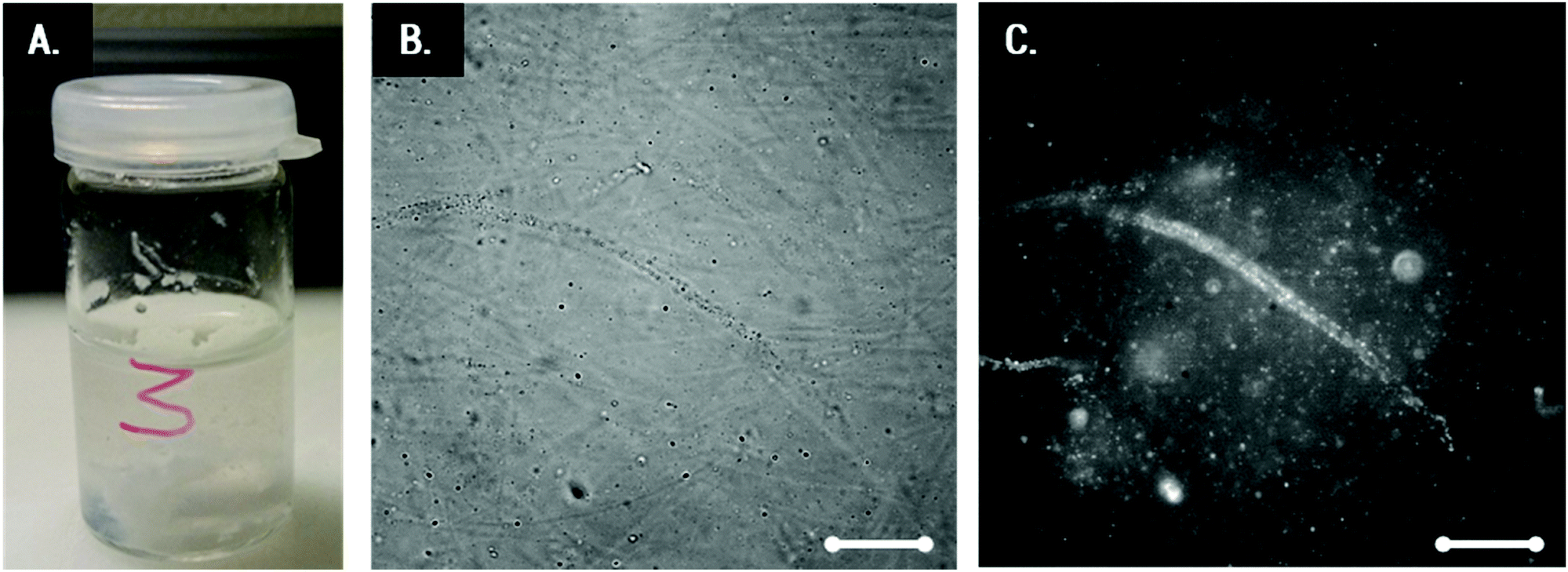 | ||
| Fig. 3 (A) Transparent 0.25 wt% Coll suspension, (B) the corresponding white light image of Coll stained with CBB, and (C) the corresponding image of the same spot including fluorescent tracer particles of diameter 0.2 μm. Scale bar represents 20 μm. | ||
Local elasticity and microstructure of lyophilized Coll suspensions obtained using MPT
According to the results of bulk rheological measurements (see Section 3.1), Coll suspensions at concentrations >0.1 wt% were in the gel state.For a more detailed investigation of the underlying microstructure, MPT measurements were performed on 0.25 wt% Coll suspensions using tracer particles of diameter 0.5 and 0.2 μm (see Fig. 4 and 5, respectively). Fig. 4A indicates that 0.5 μm tracer particles are uniformly distributed all over the sample and Fig. 4B shows that trajectories are widely spread and the individual particles explore areas much larger than their diameter. In total, 1083 trajectories were detected, but only 343 trajectories longer than 50 frames, ensuring sufficient statistical significance, were used to calculate the MSD traces shown in Fig. 4C. These MSDs vary almost linearly with lag time τ, indicating that the motion of the tracer particles is purely diffusive, i.e., the microenvironment surrounding the particles responds like a viscous liquid. According to eqn (4), the averaged MSD yields ηMPT = 4.3 ± 1.1 mPa s.
 | ||
| Fig. 4 MPT results for a 0.25 wt% Coll suspension as probed with 0.5 μm particles: (A) exemplary localization of particle centres marked in green, measured at 488 nm fluorescence illumination, (B) all trajectories localized in the same field of view (trajectories shorter than 50 frames are shown in black, and those longer than 50 frames are shown in blue) and (C) the corresponding MSD plots for trajectories of minimum 50 frame-length. The minimum measurable MSD that exceeds the static error55,58χ = 8 × 10⁻⁵ μm2 is shown as a dashed line. For each condition, 4 videos were recorded and analyzed per biological repetition and a representative set is shown here. | ||
Additionally, the value of the non-Gaussian parameter, calculated for the whole ensemble of MSDs, is α = 0.11 ± 0.04, which indicates that all tracers explored a similar environment. These results clearly reveal that 0.5 μm tracer particles only probe the solvent and not the fiber network providing the elasticity seen in bulk measurements. Presumably, tracer particles are freely diffusing in the meshes of the sample spanning Coll network and accordingly the lower limit of network mesh size is well above 0.5 μm. The viscosity of that liquid phase is about 4 times the viscosity of water, indicating that Coll is partly dissolved in the aqueous phase.
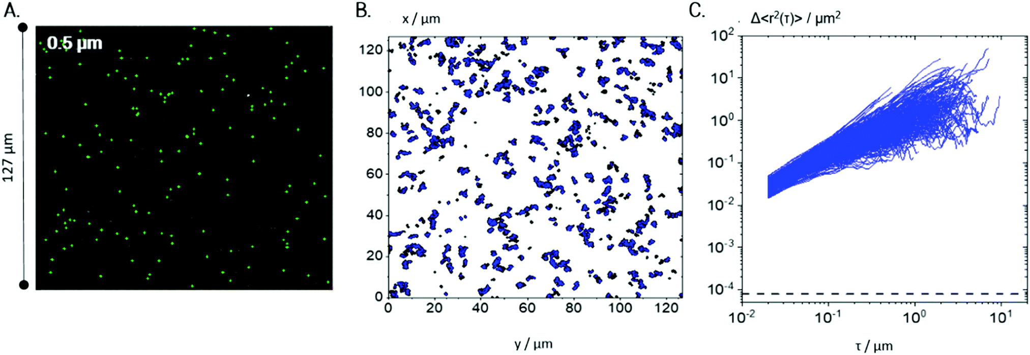
Tracer particles with 0.2 μm diameter also exhibit a uniform distribution all over the sample (see Fig. 5A). A total number of ≈450 trajectories, each composed of more than 50 frames corresponding to a lag time τ > 1 s, as typically used in conventional MPT analysis, are shown in Fig. 5B. Many particles probed areas that were much larger than their diameter, as similarly observed for the 0.5 μm particles (cf.Fig. 4B).
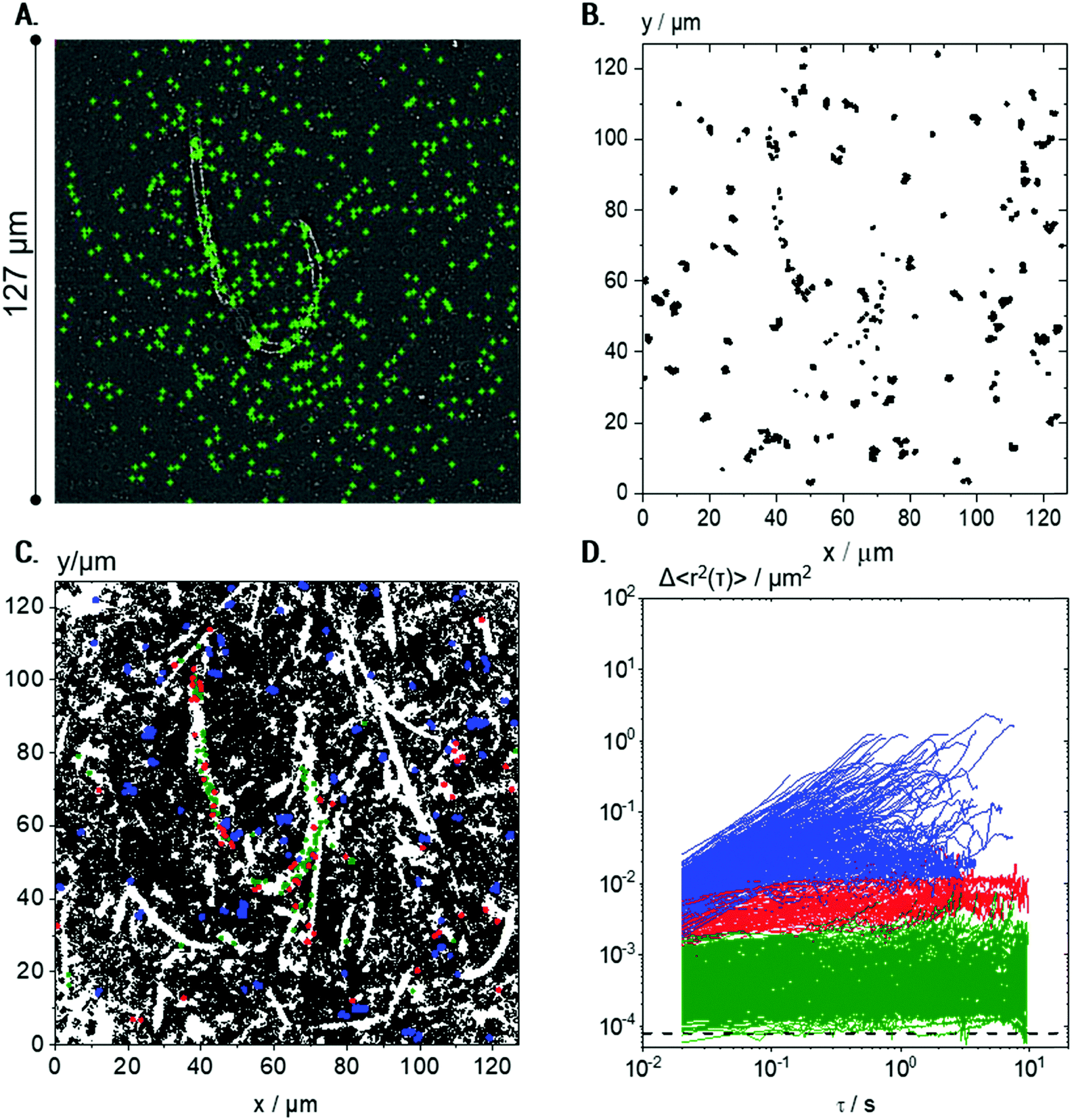 | ||
Fig. 5 Visualization of microstructures in a 0.25 wt% Coll suspension using 0.2 μm particles: (A) exemplary localization of particle centers marked in green, and measured at 488 nm fluorescence illumination, and (B) all trajectories considered for MSD calculation (≈450), i.e., short trajectories (<50 frames) were eliminated. (C) All trajectories (≈50![[thin space (1/6-em)]](https://www.rsc.org/images/entities/char_2009.gif) 000) including short ones evaluated in the same field of view (the trajectories longer than 50 frames are marked in blue, red, and green according to the MSD classification described in D); for better visualization, red, blue and green trajectories are plotted at twice the size of the black ones. (D) Corresponding MSD plots for trajectories of minimum 50 frame-length. Green MSDs are MSDs with slopes <0.5 and absolute values <10−3 μm2, red MSDs have slopes <0.5 and absolute values >10−3 μm2, and blue curves correspond to MSDs with slope >0.5. The minimum measurable MSD that exceeds the static error55,58χ = 8 × 10⁻⁵ μm2 is shown as a dashed line. For each condition, 4 videos were recorded and analyzed per biological repetition and a representative set is shown here. 000) including short ones evaluated in the same field of view (the trajectories longer than 50 frames are marked in blue, red, and green according to the MSD classification described in D); for better visualization, red, blue and green trajectories are plotted at twice the size of the black ones. (D) Corresponding MSD plots for trajectories of minimum 50 frame-length. Green MSDs are MSDs with slopes <0.5 and absolute values <10−3 μm2, red MSDs have slopes <0.5 and absolute values >10−3 μm2, and blue curves correspond to MSDs with slope >0.5. The minimum measurable MSD that exceeds the static error55,58χ = 8 × 10⁻⁵ μm2 is shown as a dashed line. For each condition, 4 videos were recorded and analyzed per biological repetition and a representative set is shown here. | ||
However, including the shorter trajectories in the overlay of subsequent images of the video sequence showing all tracer particle trajectories (Fig. 5C) allows for a more detailed insight into the microstructure of the suspension. Here, the total number of trajectories is very large, around 50000, since the small tracers in the low viscosity environment frequently enter and leave the focal plane. Surprisingly, the trajectories do not cover the whole sample, leading to the visualization of elongated white areas where no particles were present during the whole measurement. These white areas correspond to the Coll structures, which are densely packed and seem to be inaccessible to the diffusing tracer particles (see also Fig. 6).
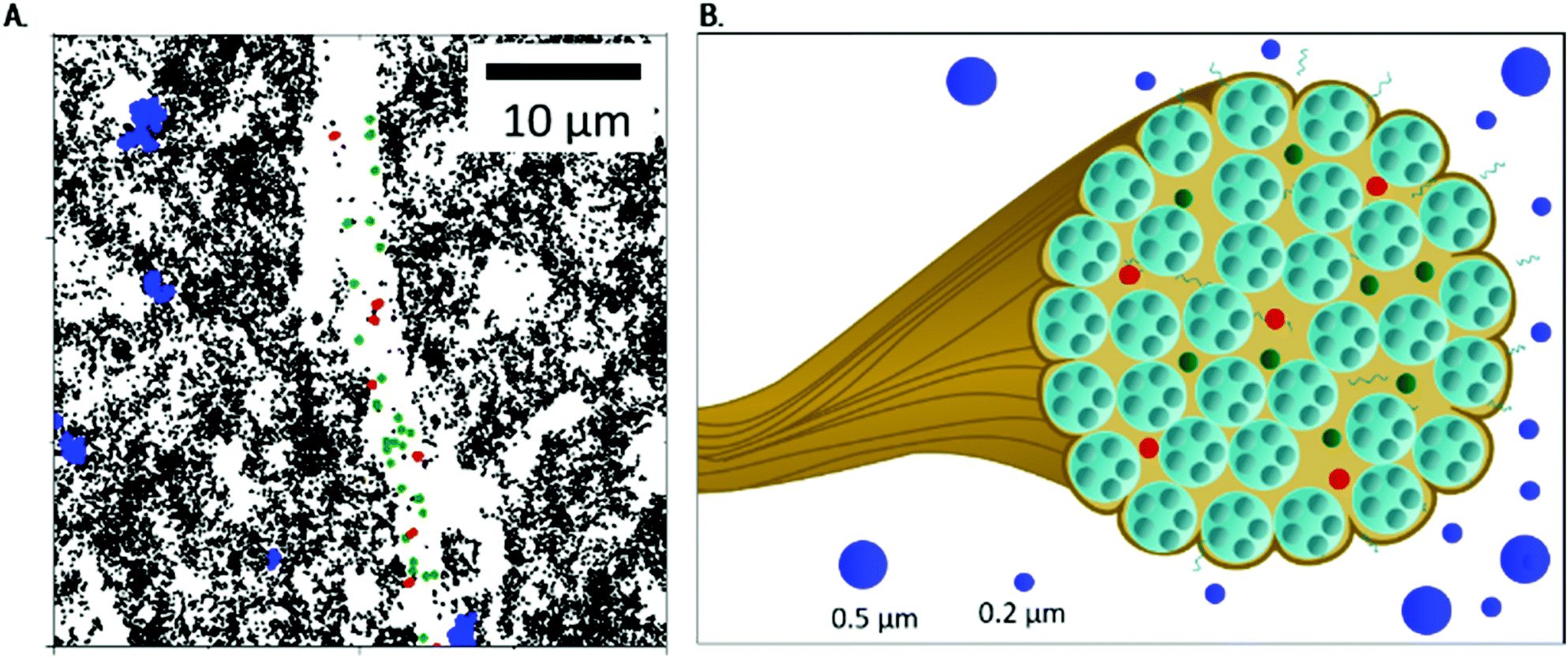 | ||
| Fig. 6 The fibrous Coll structure consisting of densely packed bundles: (A) close-up of Fig. 3B (lower area), to show localization of MPT particles in more detail, and (B) sketch of Coll dispersed in acidic solution, including the viscous surrounding, a bundle of fibrils (see Fig. 1) with areas accessible to 0.2 μm particles (shown in red and green, corresponding to particles trapped in elastic and highly elastic regions) and the dense, inaccessible core. In the viscous surrounding, 0.5 and 0.2 μm particles can be found. | ||
MSDs obtained from the 0.2 μm particles based on the trajectories of >50 frames show results completely different from those obtained for the 0.5 μm particles (cf.Fig. 4C) and provide further insight into the Coll structure. A broad variation in absolute values and time-dependence of the individual MSDs was found for the 0.2 μm particles (Fig. 5D). The non-Gaussian parameter of all MSDs increased to α = 8.3 ± 3.4, indicating a high degree of heterogeneity in the environment probed by the tracers. The ensemble of MSDs splits into three populations: Population I includes all MSDs with slopes of m < 0.5 and absolute values <10−3 μm2 (shown in green) close to the static error 〈Δr2〉 = 8 × 10⁻⁵ μm2, determined for the setup and tracer particles used here. Population II consists of all MSDs with m < 0.5 and absolute values >10−3 μm2 (red curves), and all MSDs with m > 0.5 are summarized as Population III (blue curves). The separation criteria were applied at τ = 0.1 s. Consequently, Population I (green) corresponds to particles that are located within highly elastic regions where thermal motion is strongly restricted, even at long lag times of about 10 s, and particles can be considered to be almost completely immobilized. This population comprises a broad variation of MSDs, which extends over one decade from ∼10−4 to ∼10−3 μm2. This indicates that the particles are caged in a fiber network of varying elasticity.
If the tracer particles were adsorbed on the surface of the Coll structures, a constant very low MSD of about 10−4 μm2, corresponding to the static error limit, would be expected. Tracer particles corresponding to Population II are located in regions of significantly lower elasticity, whereas Population III comprises freely diffusing tracers, located in predominantly viscous areas.
The black trajectories, shown in Fig. 5C and in Fig. 6A, correspond to short trajectories (<50 frames), which result from highly mobile particles in a viscous environment, which enter and leave the focal plane of the microscope frequently. These short trajectories correspond to low viscosity regions of the sample, and although they are not used for further MSD data evaluation, they are the key to the visualization of the sample microstructure.
Careful inspection of the localization of the trajectories corresponding to the different populations gives further insight into the heterogeneous organization of the Coll structure. For better visibility, colored trajectories were plotted with twice the size of the black ones.
Fig. 5A confirms that tracer particles of diameter 0.2 μm were uniformly distributed all over the sample. However, Fig. 5C and more clearly Fig. 6A reveal that green trajectories corresponding to particles probing a highly elastic surrounding were located within the white areas representing the Coll structure, mainly in the center. Red trajectories, corresponding to particles exploring areas of lower elasticity, were located in white regions, too. Blue trajectories, corresponding to freely viscous diffusing particles, were found only in the easily accessible regions between the white areas.
For this population, a viscosity value of 2.2 ± 0.9 mPa s was obtained, consistent with the results obtained for the 0.5 μm tracer particles. The relatively large experimental error obtained with the 0.2 μm particles is due to the fast motion of the tracers leading to a short length of the trajectories and to a broad variation of absolute MSD values (Fig. 5D, blue curves).
Our data reveal that a substantial fraction of 0.2 μm tracer particles were able to penetrate into the Coll structures. In contrast, 0.5 μm particles cannot enter these fibrous structures. Thus, the mesh size of the Coll structures can be estimated to be less than 0.5 μm.
However, as there were regions inaccessible to the 0.2 μm tracers too, we propose a Coll structure comprising bundles of dense fibers embedded in elastic regions with a broad range of different stiffness, as sketched in Fig. 6B. According to eqn (2), time-independent MSDs found for Populations I and II correspond to elastic moduli G0,MPT = 58.3 ± 7.2 and 1.8 ± 0.2 Pa, respectively. These values are in the same range as the macroscopic elastic modulus obtained using bulk shear rheometry (Fig. 2). However, it has to be emphasized that this latter quantity is determined by the network of Coll structures, the steric hindrance and the colloidal interactions among fibers and thus the agreement between absolute G0,MPT and G0,bulkv values is accidental. However, this MPT imaging technique is a powerful and versatile tool to visualize the fiber network of gel-like Coll suspensions (Fig. 5C) and beyond that provides insight into the elastic properties of the Coll structures or fiber bundles with their heterogeneous organization.
Concentration dependence of local elasticity and network structure
In the following, we will discuss the change in local viscoelasticity and network structure upon variation of Coll concentration based on MPT experiments performed using 0.2 μm tracer particles. Overlay images showing the complete trajectories of all tracers and the variation of the corresponding MSDs as a function of lag time for Coll concentrations from 0.05 up to 1 wt% are shown in Fig. 7A and B, respectively.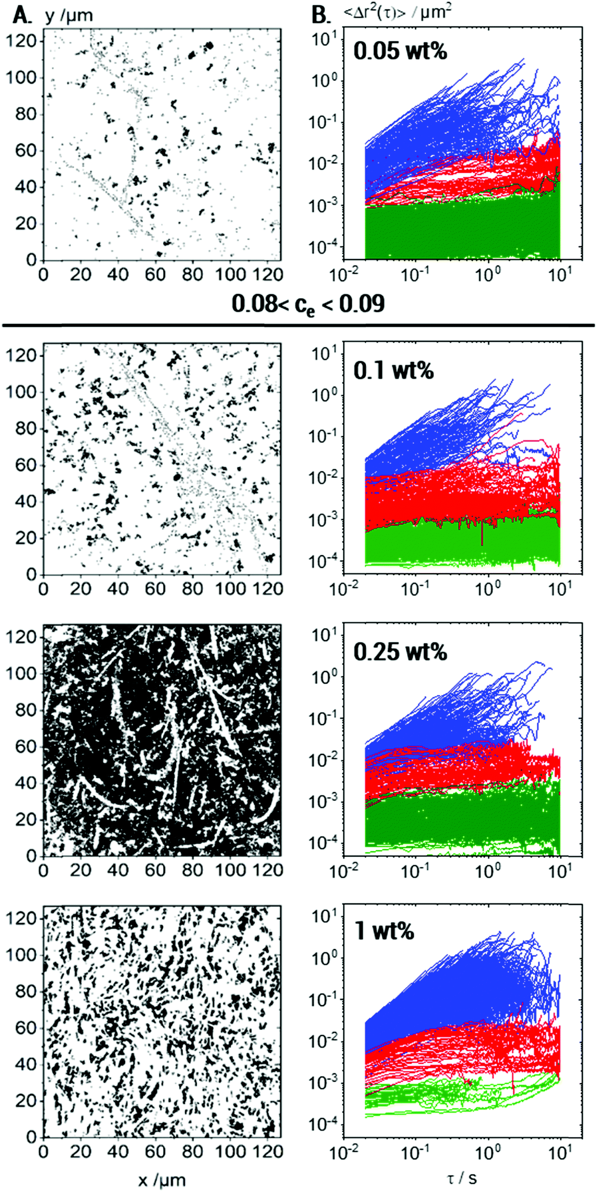 | ||
| Fig. 7 Effect of Coll concentration on MPT with 0.2 μm tracers: (A) all trajectories; (B) MSD plots corresponding to trajectories of min. 50 frames, showing three particle fractions: almost immobilized (green), elastically trapped (red) and freely diffusing (blue). For each concentration, 4 videos were recorded and analyzed per biological repetition and the results for one representative set are shown here. | ||
At all investigated Coll concentrations, a broad variety in the absolute values and time-dependence of MSDs is found (Fig. 7B), and the calculated non-Gaussian parameter α ≫ 1 is summarized in Table 1. This latter value is maximal at the gelation concentration, as already reported for colloidal dispersions of spheres with weak attractive interactions56 and clay suspensions57 where a strong increase in heterogeneity was observed at the sol–gel transition.
| Coll concentration | 0.05 wt% | 0.1 wt% | 0.25 wt% | 1 wt% |
|---|---|---|---|---|
| α all MSDs | 18 ± 2 | 31 ± 16 | 8 ± 3 | 2 ± 0 |
| Population I (green) | 75% | 52% | 38% | 2% |
| Population II (red) | 6% | 26% | 11% | 3% |
| Population III (blue) | 18% | 22% | 51% | 96% |
| η popIII/mPa s | 5.2 ± 2.8 | 3.6 ± 1.8 | 2.2 ± 0.9 | 4.8 ± 2.9 |
In all cases, three populations of tracer particles classified according to their slope in the log–log representation of MSD vs. τ and absolute MSD values are found. The separation criteria are the same as those defined in the previous section.
The fraction of tracers in each population at different Coll concentrations is also summarized in Table 1. Besides that, many short trajectories (<50 frames length) were observed (Fig. 7A), indicating a very low viscosity of the surrounding medium in accordance with the viscosity value of 5.2 ± 2.8 mPa s calculated from the MSDs of Population III (see Table 1).
At 0.05 wt% Coll concentration, large areas of the field of view are white, i.e., not accessible to the 0.2 μm tracer particles. Consistent with the measurements performed at higher concentrations, these large areas correspond to collagen fibers or aggregates loosely packed but obviously inaccessible to the tracers. The regions, which were probed by the particles, are heterogeneous even in this low viscosity sample well below the sol/gel transition. Three populations of tracer particles can be distinguished similarly to the case for the gelled sample described above, i.e., some tracer particles explore a viscous matrix, others are trapped in a weakly elastic environment and a large fraction is found to be almost immobilized in highly elastic regions. Fiber like structures with a core–shell structure as outlined above exist even at Coll concentrations as low as 0.05 wt%, well below the sol/gel transition. As mentioned before, these structures obviously cover large areas of the solution. Some individual fibers are visible due to the elastically trapped tracer particles lined-up along these structures. They do not, however, form a percolating network, as indicated by the viscous response found using bulk rheometry.
At 0.1 wt% Coll concentration, just above the sol/gel transition, the white areas shrink, i.e., the regions dilute enough to be accessible to the 0.2 μm tracers increase in size. As the Coll concentration is doubled compared to the liquid sample discussed above, this indicates that the phase separation between dense Coll structures and the viscous matrix is more pronounced, and the white areas must correspond to denser Coll structures than in the more dilute solution. In the overlay image of the 0.25 wt% Coll solution, the heterogeneity, i.e., the separation between dense Coll structures and the surrounding low viscosity solvent, is even more pronounced. The inaccessible white areas show up as elongated, slender filaments or fibrils forming an extended percolating network providing the macroscopic gel-like texture. The Coll structures or fibers are denser than at lower concentrations. This shows up in the higher contrast between the dark areas of very low viscosity and the filamentous white areas as well as in the large fraction of tracers almost immobilized in the highly elastic areas of the fibers. Further increasing the Coll concentration up to 1 wt% results in a denser network of elongated fibers as expected in line with a higher bulk elastic modulus. The Coll structure seems to be further densified and the fraction of tracer particles able to diffuse into this structure and to be elastically trapped there is clearly lower than that at lower Coll concentrations. In particular, almost immobile tracers, which are embedded in highly elastic regions, are hardly found, whereas a large fraction of tracers freely diffuses in the viscous matrix.
In summary, MPT measurements inform us about the non-uniform structure of collagen aggregates and how collagen slender fibers or fiber bundles evolve at concentrations above the macroscopic sol–gel transition. As the collagen concentration increases, the inaccessible areas for the tracer particles shrink and rearrange into slender bundles of collagen fibers, i.e., the collagen aggregates strongly densify with increasing collagen concentration. Another otherwise hardly accessible result is that the diffusion coefficient corresponding to the linearly increasing MSDs of Population III and hence the calculated viscosity of the continuous phase of the fiber suspensions are essentially independent of Coll concentration, as shown in Table 1. This result indicates that the fraction of collagen molecularly dissolved in the aqueous phase is independent of the total collagen concentration in the solution.
As the viscoelastic behavior of Coll solutions is determined by heterogeneous, supramolecular Coll structures present even at concentrations well below the sol–gel transition, we aimed at investigating this self-assembly phenomenon in more detail. Hence, large Coll structures were removed by filtration.
Prior to filtration, 0.1 wt% Coll solutions showed, as already discussed above, a sample spanning network of elastic Coll structures. Consequently, in bulk measurements (see Fig. 8A), G′ was frequency independent and dominating over G′′. Directly after filtration (Fig. 8A, row 2), the results appear noisy and this is due to the fact that the sample is not in equilibrium anymore and its structure is heterogeneous on a macroscopic scale. In that sense, rheological data obtained some seconds after filtration have to be treated as apparent values. However, a predominantly viscous behavior with a pronounced frequency-dependence of G′ and G′′ was observed, indicating that the gel structure was removed or destroyed.
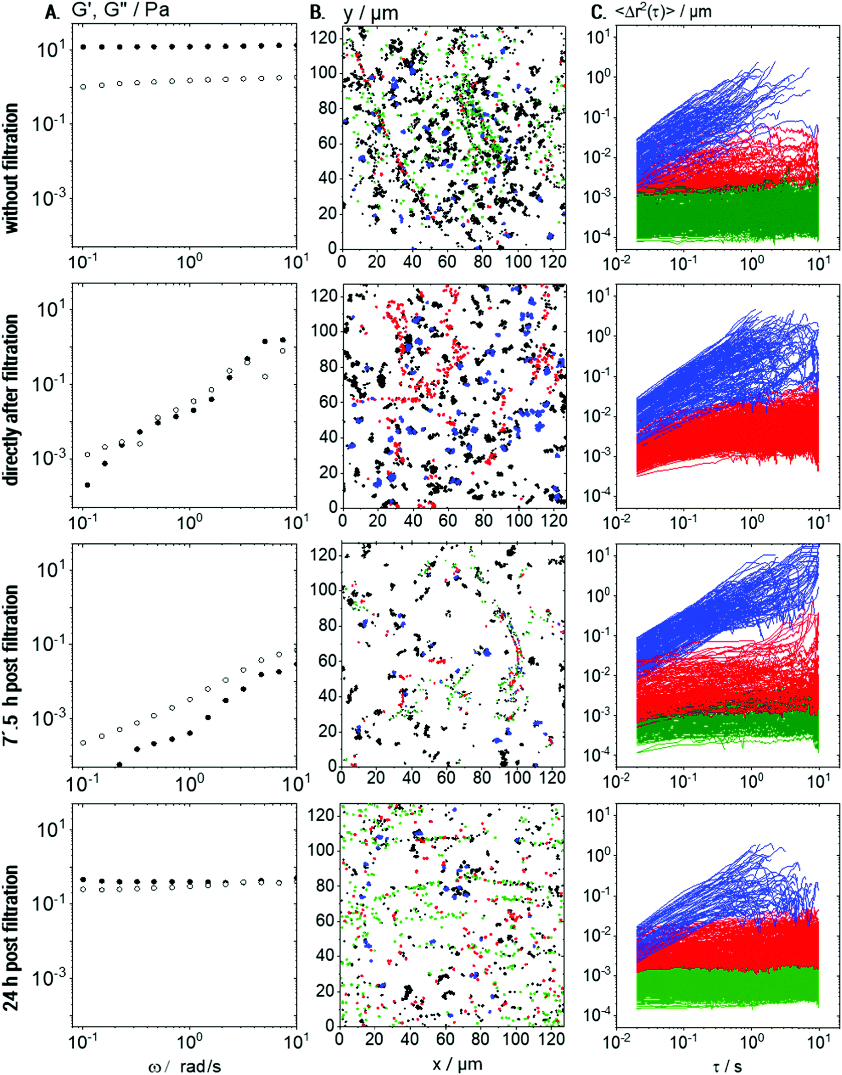 | ||
| Fig. 8 Coll self-assembly after removing large structures by filtration with 1.2 μm pore size: (A) storage and loss modulus, G′ (full symbols) and G′′ (hollow symbols), respectively, vs. frequency, obtained using rotational rheometry. (B) Trajectories of all 0.2 μm tracer particles. Trajectories of tracers in viscous surroundings are shown in blue, those of elastically trapped tracers are shown in red and trajectories of almost immobilized particles are shown in green. Trajectories <50 frames in length are shown in black but were not considered for MSD calculations. (C) MSD plots showing the different populations using the same color code as in (B). Data are shown for 0.1 wt% Coll solutions prior to filtration (row 1), directly after filtration (row 2), and 7.5 h (row 3) and 24 h (row 4) after filtration. For each time-point, 4 videos per biological repetition were recorded and analyzed and a representative set is shown here. | ||
The viscosity deduced from the MSDs of the freely diffusing particles (blue) did not change upon filtration, but, as expected, fewer elastically trapped tracer particles were seen when comparing row 2 to row 1 in Fig. 8B and C.
The measured protein concentration of 0.05 ± 0.01 wt% after filtration corresponds to the sol state (see Fig. 2) and, again, we find elastically trapped tracer particles (compare Fig. 8B, row 2 to top row Fig. 7B). However, the size of continuous elastic areas was drastically reduced (compare Fig. 8B, row 2 to top row Fig. 7B) and the almost immobilized fraction (green trajectories) even disappeared completely. The fraction of elastically trapped (red) particles re-increases over time and even almost immobilized particles (green population) reappear after 7.5 h waiting time but no percolating network can be seen (Fig. 8B, row 3). This is consistent with the still predominantly viscous behavior observed in bulk rheometry (row 3 in Fig. 8A). After 24 h post-filtration time, however, the gel-like behavior reappears (G′, G′′ independent of frequency) and MPT data show that a sample-spanning network structure of Coll fibers has recovered (row 4 in Fig. 8).
However, the modulus G0,bulk = 1.6 ± 0.5 Pa was one order of magnitude lower than that prior to filtration (G0,bulk = 13 ± 1 Pa), which is attributed to the lower Coll concentration and even 4 days after filtration, the initial plateau modulus is not recovered. Moreover, after 24 h, G′ and G′′ are both independent of frequency and exhibit almost the same absolute values. Such a behavior is unphysical for homogeneous and isotropic materials and thus may be attributed to sample heterogeneities on a macroscopic level, which can be seen in the MPT data (Fig. 8B and C). It should be noted that the freshly prepared solution with 0.05 wt% Coll does not exhibit such a behavior and remains in the sol state even after 4 days of storage. This difference is attributed to the different size distribution of Coll aggregates or fibers in the filtered compared to the untreated solution.
From a comparison of the samples measured in the same chamber after 24 h and newly filled channels, we were able to exclude any drying effects or mechanical influences on this network reformation. In summary, we conclude that MPT is a powerful tool to monitor the self-assembly of Coll in situ.
Structural properties of native collagen I solutions
For comparison with lyophilized collagen solutions, ready-to use solutions of native collagen I were investigated too. These solutions do not show the sol–gel transition observed in the solutions made from lyophilized Coll, and up to a concentration of 1 wt%, these solutions behave almost like Newtonian low viscosity fluids, as exemplarily shown in Fig. 9A for the 0.25 wt% solution with η = 30.0 ± 1.5 mPa s. Flow behavior changes from Newtonian to weakly viscoelastic in the concentration range up to 1 wt%; however, a sol–gel transition is not observed in this concentration range. The absolute viscosity of the 0.25 wt% solution is about 10 times higher than that for the solutions made from lyophilized Coll below the sol–gel transition, clearly indicating that a larger Coll fraction is molecularly dissolved. Trajectory plots and MSDs, derived from MPT measurements performed on a 0.25 wt% native collagen I solution with tracer particles of diameter 0.2 μm, are shown in Fig. 9B and C, respectively.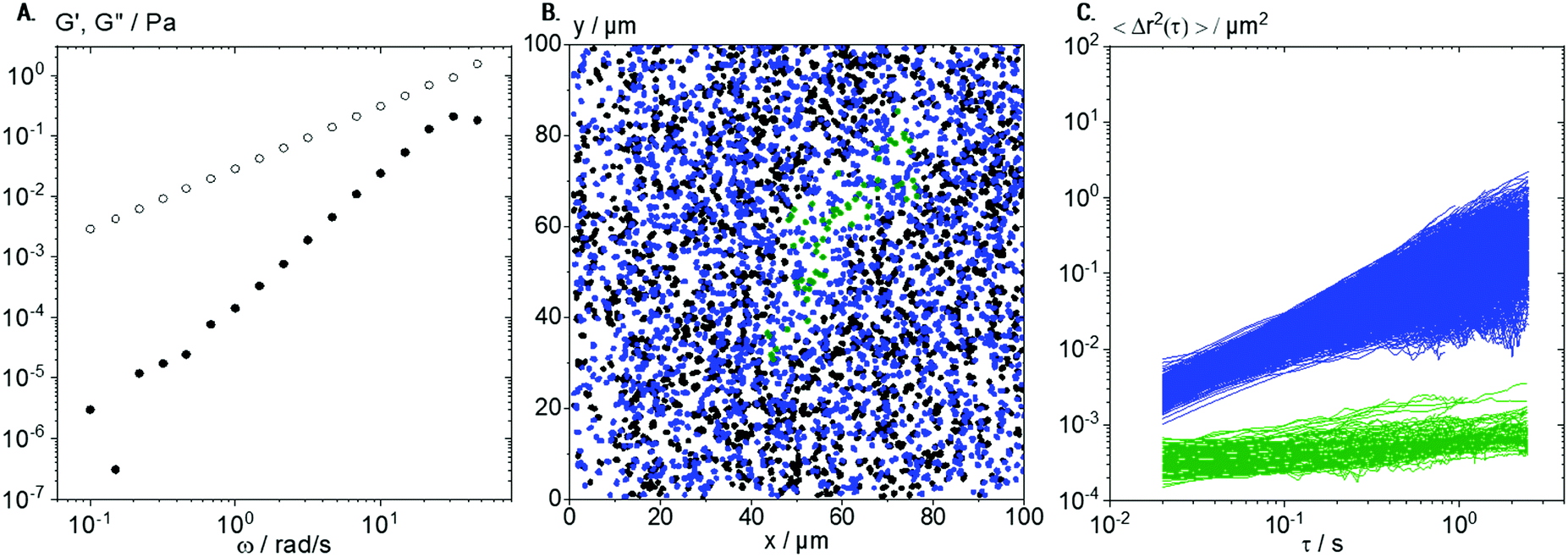 | ||
| Fig. 9 Characterization of 0.25 wt% native collagen solution: (A) G′ (full symbols) and G′′ (hollow symbols) obtained using small amplitude oscillatory shear rheometry versus frequency. (B) Overlay of trajectories of elastically trapped 0.2 μm tracer particles (green) and freely diffusing tracers in viscous surroundings (blue). All trajectories shorter than 50 frames are shown in black. (C) Respective MSD plots for all trajectories longer than 50 frames. For each biological repetition, 4 videos were recorded and analyzed and a representative set is shown here. | ||
As for the solution made from lyophilized Coll, a broad variation in absolute values and time-dependence of the calculated individual MSDs was found (see Fig. 3B). However, here, we found only two populations of MSDs, one with slope m > 0.5 (blue) and the other with m < 0.5 and absolute value <10−3 μm2 (green). In the native collagen I samples, the freely diffusing particles are the dominant fraction of tracers (96%) and the corresponding viscosity value ηMPT = 78 ± 8 mPa s agrees reasonably well with viscosity data obtained from bulk mechanical rheometry. We hypothesize that the viscosity value deduced from MPT is systematically higher because of sample heterogeneity: besides the blue trajectories (Fig. 9C) used to calculate the viscosity, we observe a large fraction of very short trajectories presumably corresponding to areas of lower viscosity.
The small fraction of elastically trapped tracer particles exhibits a very low absolute MSD value close to the static error of our set-up, i.e., they are almost immobilized. These results indicate the formation of more homogeneous and stiffer structures in native collagen I solutions as compared to samples based on lyophilized Coll.
The plot of trajectories in Fig. 9B shows the formation of elastic areas (see green trajectories), as already observed for solutions of lyophilized Coll (see Fig. 5C). However, these areas are fewer in number, more roundish, shorter, and broader. These structures are not able to form a percolating network consistent with the predominantly viscous behavior found in bulk rheological measurements on native collagen I solutions (see Fig. 9A). However, the existence of such supramolecular aggregates even in low viscosity Coll solutions can be seen clearly in MPT experiments but not from conventional light microscopy. These results further confirm that MPT is a versatile tool to characterize different types of collagen solutions and the structure of included structures or fibers in situ.
Conclusions
Classical bulk rheometry and multiple-particle tracking microrheology have been employed to gain insight into the bulk viscoelasticity as well as structural and local viscoelastic properties of acidic Coll solutions. As already observed for a broad range of other materials, MPT and bulk data are not in agreement,33–36,39,40 and the explanation for this discrepancy is the presence of heterogeneities. Overlaying subsequent images of MPT video sequences allowed for a direct visualization of the fiber network in suspensions of lyophilized Coll. For all concentrations in the range from 0.05 to 1 wt%, MPT experiments performed with tracer particles of diameter 0.2 μm yielded a very broad distribution of mean square displacements (MSDs) in terms of time-dependence as well as absolute values. Some tracer particles diffused freely with a diffusion coefficient indicating that part of the Coll is dissolved in the aqueous phase, yielding similar viscosities as the bulk measurements for concentrations below the sharp sol–gel transition observed at ccrit ≈ 0.08–0.09 wt%. According to these viscosity values, the amount of dissolved Coll is independent of the total Coll concentration. However, even at concentrations well below the macroscopic sol–gel transition, other MSD traces approached a constant value at long lag times, i.e., these particles were trapped in an elastic environment. We distinguished two populations of elastically trapped particles according to the order of magnitude difference in absolute MSD values. These particles were found within Coll structures. This suggests that the Coll aggregates presumably comprise multiple dense bundles not permeable for the 0.2 μm particles embedded in a swollen surrounding layer accessible to the 0.2 μm tracer particles, but with largely varying stiffness according to the broad variation in absolute values of the corresponding time-independent MSDs. In contrast, the 0.5 μm particles were not able to penetrate these fiber bundle structures. These tracers diffused freely in the aqueous solution and the measured viscosity was found to be similar to the value obtained from the ensemble of freely diffusing smaller particles. The fraction of almost immobilized 0.2 μm particles, found in the Coll structures, decreased with increasing Coll concentration, and we attribute this to an increasing packing density of the fibers progressively preventing access by the tracer particles.MPT and bulk rheological measurements were also used to monitor the Coll fiber self-assembly process. After removing larger Coll structures by filtration, the reformation of the sample-spanning network was observed within 24 h, resulting in a macroscopic sol–gel-transition. Surprisingly, this network structure recovers although the total Coll concentration after filtration is significantly lower than ccrit.
The investigation of native collagen I solutions revealed a higher fraction of molecularly dissolved Coll, and also fewer elastic regions that were less widespread than those in the samples based on lyophilized Coll at the same concentration were observed. This is again in good accordance with the respective viscous behavior observed using bulk rheometry up to Coll concentrations of 1 wt%.
According to our observations, particle tracking-based microrheology imaging serves as a powerful tool for the in situ analysis of the supramolecular structure and local viscoelasticity of dispersed Coll or other biopolymer fibers on a submicron length scale including the real-time monitoring of structure formation or structural transitions. Thus, this microrheology imaging method is perfectly suitable for studying structural properties of fiber suspensions where conventional microscopy techniques fail.
Conflicts of interest
There are no conflicts to declare.Acknowledgements
We acknowledge the experimental assistance of Lea Bensinger, who performed most of the MPT experiments in our lab, and Dr Carsten Radtke's help with BCA assays at the KIT molecular separation group (MAB).Notes and references
- (a) G. K. Batchelor, J. Fluid Mech., 1971, 46, 813–829 CrossRef; (b) S. M. Dinh and R. C. Armstrong, J. Rheol., 1984, 28, 207–227 CrossRef CAS; (c) C. J. S. Petrie, J. Non-Newtonian Fluid Mech., 1999, 87, 369–402 CrossRef CAS , http://www.sciencedirect.com/science/article/pii/S0377025799000695.
- (a) M. A. Bibbo, S. M. Dinh and R. C. Armstrong, J. Rheol., 1985, 29, 905–929 CrossRef; (b) A. Ramazani S. A., A. Ait-Kadi and M. Grmela, J. Rheol., 2001, 45, 945–962 CrossRef; (c) M. Sepehr, P. J. Carreau, M. Moan and G. Ausias, J. Rheol., 2004, 48, 1023–1048 CrossRef CAS.
- M. P. Petrich, D. L. Koch and C. Cohen, J. Non-Newtonian Fluid Mech., 2000, 95, 101–133 CrossRef CAS , http://www.sciencedirect.com/science/article/pii/S0377025700001725.
- (a) R. R. Sundararajakumar and D. L. Koch, J. Non-Newtonian Fluid Mech., 1997, 73, 205–239 CrossRef CAS , http://www.sciencedirect.com/science/article/pii/S0377025797000438; (b) S. Yamamoto and T. Matsuoka, Comput. Mater. Sci., 1999, 14, 169–176 CrossRef CAS.
- M. Keshtkar, M.-C. Heuzey, P. J. Carreau, M. Rajabian and C. Dubois, J. Rheol., 2010, 54, 197 CrossRef CAS , https://sor.scitation.org/doi/pdf/10.1122/1.3301245.
- G. Wang, W. Yu and C. Zhou, Eur. J. Mech. B Fluids, 2006, 25, 337–347 CrossRef , http://www.sciencedirect.com/science/article/pii/S0997754605000749.
- (a) L. H. Switzer and D. J. Klingenberg, J. Rheol., 2003, 47, 759–778 CrossRef CAS; (b) C. G. Joung, N. Phan-Thien and X. J. Fan, J. Non-Newtonian Fluid Mech., 2001, 99, 1–36 CrossRef CAS , http://www.sciencedirect.com/science/article/pii/S0377025701001136; (c) M. Rajabian, C. Dubois and M. Grmela, Rheol. Acta, 2005, 44, 521–535 CrossRef CAS , https://link.springer.com/content/pdf/10.1007/s00397-005-0434-7.pdf.
- B. M. Marín-Santibáñez, J. Pérez-González and L. de Vargas, Rheol. Acta, 2010, 49, 177–189 CrossRef.
- A. Le Duc, B. Vergnes and T. Budtova, Composites, Part A, 2011, 42, 1727–1737 CrossRef , http://www.sciencedirect.com/science/article/pii/S1359835X11002338.
- V. Herle, P. Fischer and E. J. Windhab, Langmuir, 2005, 21, 9051–9057 CrossRef CAS PubMed.
- D. W. de Kort, T. Nikolaeva and J. A. Dijksman, Modern Magnetic Resonance, Springer International Publishing, 2018, pp. 1589–1608 Search PubMed.
- F. M. Ross, Science, 2015, 350, aaa9886 CrossRef PubMed , https://science.sciencemag.org/content/sci/350/6267/aaa9886.full.pdf.
- (a) E. N. Landis and D. T. Keane, Mater. Charact., 2010, 61, 1305–1316 CrossRef CAS; (b) P. J. Schilling, B. R. Karedla, A. K. Tatiparthi, M. A. Verges and P. D. Herrington, Compos. Sci. Technol., 2005, 65, 2071–2078 CrossRef CAS; (c) D. Wildenschild, C. M. P. Vaz, M. L. Rivers, D. Rikard and B. S. B. Christensen, J. Hydrol., 2002, 267, 285–297 CrossRef.
- R. Henderson, Q. Rev. Biophys., 1995, 28, 171–193 CrossRef CAS PubMed.
- (a) G. Agoda-Tandjawa, S. Durand, S. Berot, C. Blassel, C. Gaillard, C. Garnier and J.-L. Doublier, Carbohydr. Polym., 2010, 80, 677–686 CrossRef CAS; (b) M. Y. Kim and J. Lee, Carbohydr. Polym., 2011, 84, 1329–1336 CrossRef CAS.
- D. Zhang, X. Wu, J. Chen and K. Lin, Bioact. Mater., 2018, 3, 129–138 CrossRef PubMed , http://www.sciencedirect.com/science/article/pii/S2452199X17300506.
- C. F. Marques, G. S. Diogo, S. Pina, J. M. Oliveira, T. H. Silva and R. L. Reis, J. Mater. Sci.: Mater. Med., 2019, 30, 32, DOI:10.1007/s10856-019-6234-x.
- C. T. Thorpe, C. P. Udeze, H. L. Birch, P. D. Clegg and H. R. C. Screen, J. R. Soc., Interface, 2012, 9, 3108–3117 CrossRef PubMed.
- M. J. Buehler, Proc. Natl. Acad. Sci. U. S. A., 2006, 103, 12285–12290 CrossRef CAS PubMed.
- Collagen. Structure and Mechanics, ed. P. Fratzl, Springer Science + Business Media LLC, Boston, MA, 2008 Search PubMed.
- P. Kannus, Scand. J. Med. Sci. Spor., 2000, 10, 312–320 CrossRef CAS PubMed.
- A. Gautieri, S. Vesentini, A. Redaelli and M. J. Buehler, Nano Lett., 2011, 11, 757–766 CrossRef CAS PubMed.
- Hyaluronan. Proceedings of an International Meeting, September 2000, North East Wales Institute, ed. J. F. Kennedy, Glyn O. Phillips, P. A. Williams and V. C. Hascall, Woodhead Publishing, UK, 2002 Search PubMed.
- A. K. Harvey, M. S. Thompson, L. E. Cochlin, P. A. Raju, Z. Cui, H. R. Cornell, P. A. Hulley and J. M. Brady, Ann. Brit. Machine Vision Assoc., 2009, 2009, 1–11 Search PubMed.
- S. Varma, J. P. R. O. Orgel and J. D. Schieber, Biophys. J., 2016, 111, 50–56 CrossRef CAS PubMed.
- E. Gentleman, A. N. Lay, D. A. Dickerson, E. A. Nauman, G. A. Livesay and K. C. Dee, Biomaterials, 2003, 24, 3805–3813 CrossRef CAS PubMed.
- K. A. Jansen, A. J. Licup, A. Sharma, R. Rens, F. C. MacKintosh and G. H. Koenderink, Biophys. J., 2018, 114, 2665–2678 CrossRef CAS PubMed.
- (a) G. Lai, Y. Li and G. Li, Int. J. Biol. Macromol., 2008, 42, 285–291 CrossRef CAS PubMed; (b) F. H. Nestler, S. Hvidt, J. D. Ferry and A. Veis, Biopolymers, 1983, 22, 1747–1758 CrossRef CAS PubMed; (c) E. J. Amis, C. J. Carriere, J. D. Ferry and A. Veis, Int. J. Biol. Macromol., 1985, 7, 130–134 CrossRef CAS; (d) F. Gobeaux, E. Belamie, G. Mosser, P. Davidson and S. Asnacios, Soft Matter, 2010, 6, 3769–3777 RSC.
- (a) M. P. E. Wenger, L. Bozec, M. A. Horton and P. Mesquida, Biophys. J., 2007, 93, 1255–1263 CrossRef CAS PubMed; (b) E. A. G. Chernoff and D. A. Chernoff, J. Vac. Sci. Technol., A, 1992, 10, 596–599 CrossRef CAS.
- K. Kato, G. Bar and H.-J. Cantow, Eur. Phys. J. E: Soft Matter Biol. Phys., 2001, 6, 7–14 CrossRef CAS.
- (a) M. Shayegan and N. R. Forde, PLoS One, 2013, 8, e70590 CrossRef CAS PubMed; (b) A. Parekh and D. Velegol, Ann. Biomed. Eng., 2007, 35, 1231–1246 CrossRef PubMed; (c) D. Velegol and F. Lanni, Biophys. J., 2001, 81, 1786–1792 CrossRef CAS PubMed; (d) O. Latinovic, L. A. Hough and H. Daniel Ou-Yang, J. Biomech., 2010, 43, 500–505 CrossRef PubMed.
- (a) Y. Tseng and D. Wirtz, Biophys. J., 2001, 81, 1643–1656 CrossRef CAS PubMed , http://www.sciencedirect.com/science/article/pii/S0006349501758183; (b) J. Apgar, Y. Tseng, E. Fedorov, M. B. Herwig, S. C. Almo and D. Wirtz, Biophys. J., 2000, 79, 1095–1106 CrossRef CAS PubMed , http://www.sciencedirect.com/science/article/pii/S0006349500763636.
- R. Bansil, J. P. Celli, J. M. Hardcastle and B. S. Turner, Front. Immunol., 2013, 4, 310 Search PubMed.
- A. Gross, A. Torge, U. F. Schaefer, M. Schneider, C.-M. Lehr and C. Wagner, J. Mech. Behav. Biomed. Mater., 2017, 71, 216–222 CrossRef PubMed.
- J. Celli, B. Gregor, B. Turner, N. H. Afdhal, R. Bansil and S. Erramilli, Biomacromolecules, 2005, 6, 1329–1333 CrossRef CAS PubMed.
- X. Murgia, P. Pawelzyk, U. F. Schaefer, C. Wagner, N. Willenbacher and C.-M. Lehr, Biomacromolecules, 2016, 17, 1536–1542 CrossRef CAS PubMed.
- S. K. Lai, Y.-Y. Wang, D. Wirtz and J. Hanes, Adv. Drug Delivery Rev., 2009, 61, 86–100 CrossRef CAS PubMed , http://www.sciencedirect.com/science/article/pii/S0169409X08002603.
- (a) C. M. Hale, S. X. Sun and D. Wirtz, PLoS One, 2009, 4, e7054 CrossRef PubMed , https://pubmed.ncbi.nlm.nih.gov/19756147; (b) Y. Tseng, T. P. Kole and D. Wirtz, Biophys. J., 2002, 83, 3162–3176 CrossRef CAS PubMed; (c) J. C. Crocker and B. D. Hoffman, in Methods in Cell Biology: Cell Mechanics, Academic Press, 2007, vol. 83, pp. 141–178 Search PubMed.
- A. Papagiannopoulos, K. Sotiropoulos and S. Pispas, Food Hydrocolloids, 2016, 61, 201–210 CrossRef CAS.
- M. Caggioni, P. T. Spicer, D. L. Blair, S. E. Lindberg and D. A. Weitz, J. Rheol., 2007, 51, 851–865 CrossRef CAS.
- J. Roether, S. Bertels, C. Oelschlaeger, M. Bastmeyer and N. Willenbacher, PLoS One, 2018, 13, e0207397 CrossRef CAS PubMed.
- P. Pawelzyk, N. Mücke, H. Herrmann and N. Willenbacher, PLoS One, 2014, 9, e93194 CrossRef PubMed.
- (a) M. J. Skaug and D. K. Schwartz, Ind. Eng. Chem. Res., 2015, 54, 4414–4419 CrossRef CAS; (b) Y. Cai and D. K. Schwartz, ACS Appl. Mater. Interfaces, 2017, 9, 43258–43266 CrossRef CAS PubMed.
- M. Daviran, S. M. Longwill, J. F. Casella and K. M. Schultz, Soft Matter, 2018, 14(16), 3078–3089 RSC.
- (a) M. E. Nimni and R. D. Harkness, Collagen Volume I Biochemistry, 1988 Search PubMed; (b) W. Friess and G. Lee, Biomaterials, 1996, 17, 2289–2294 CrossRef CAS PubMed; (c) W. Friess, Eur. J. Pharm. Biopharm., 1998, 45, 113–136 CrossRef CAS PubMed.
- T. G. Mason and D. A. Weitz, Phys. Rev. Lett., 1995, 74, 1250–1253 CrossRef CAS PubMed.
- T. A. Waigh, Rep. Prog. Phys., 2005, 68, 685–742 CrossRef.
- M. L. Gardel, M. T. Valentine and D. A. Weitz, in Microscale diagnostic techniques, ed. K. S. Breuer, Springer, 2005, pp. 1–49 Search PubMed.
- M. T. Valentine, Z. E. Perlman, M. L. Gardel, J. H. Shin, P. Matsudaira, T. J. Mitchison and D. A. Weitz, Biophys. J., 2004, 86, 4004–4014 CrossRef CAS PubMed.
- D. Wirtz, Annu. Rev. Biophys., 2009, 38, 301–326 CrossRef CAS PubMed.
- A. Kowalczyk, C. Oelschlaeger and N. Willenbacher, Meas. Sci. Technol., 2015, 26, 15302 CrossRef.
- J. C. Crocker and David G. Grier, J. Colloid Interface Sci., 1996, 179, 298–310 CrossRef CAS.
- L. van Hove, Phys. Rev., 1954, 95, 249 CrossRef CAS.
- E. R. Weeks, J. C. Crocker, A. C. Levitt, A. Schofield and D. A. Weitz, Science, 2000, 287, 627 CrossRef CAS PubMed.
- T. Savin and P. S. Doyle, Biophys. J., 2005, 88, 623 CrossRef CAS PubMed.
- C. J. Dibble, M. Kogan and M. J. Solomon, Phys. Rev. E: Stat., Nonlinear, Soft Matter Phys., 2006, 74, 41403 CrossRef PubMed.
- M. Pilavtepe, S. M. Recktenwald, R. Schuhmann, K. Emmerich and N. Willenbacher, J. Rheol., 2018, 62, 593–605 CrossRef CAS.
- A. Kowalczyk, C. Oelschlaeger and N. Willenbacher, Polymer, 2015, 58, 170 CrossRef CAS.
| This journal is © The Royal Society of Chemistry 2020 |