
 Open Access Article
 This Open Access Article is licensed under a
 Creative Commons Attribution 3.0 Unported Licence
Membrane permeability to water measured by microfluidic trapping of giant vesicles†
Tripta
Bhatia
 *,
Tom
Robinson
and
Rumiana
Dimova
*
*,
Tom
Robinson
and
Rumiana
Dimova
*
Theory & Biosystems, Max Planck Institute of Colloids and Interfaces (MPIKG), 14424 Potsdam, Germany. E-mail: tripta.bhatia@mpikg.mpg.de; dimova@mpikg.mpg.de
First published on 16th July 2020
Abstract
We use a microfluidic method to estimate the water permeability coefficient (p) of membranes. As model lipid membranes we employ giant unilamellar vesicles (GUVs) composed of palmitoyloleoyl phosphatidylcholine and cholesterol (10 mol%). We have developed a microfluidic device with multiple chambers to trap GUVs and allow controlled osmotic exchange. Each chamber has a ring-shaped pressure-controlled valve which upon closure allows isolation of the GUVs in a defined volume. Opening the valves leads to a rapid fluid exchange between the trapping region and the microchannel network outside, thus allowing precise control over solution concentration around the GUVs contrary to other experimental approaches for permeability measurements reported in the literature. The area and volume changes of individual vesicles are monitored with confocal microscopy. The solute concentration in the immediate vicinity of the GUVs, and thus the concentration gradient across the membrane, is independently assessed. The data are well fitted by a simple model for water permeability which assumes that the rate of change in volume of a GUV per unit area is linearly proportional to concentration difference with permeability as the proportionality constant. Experiments of GUV osmotic deflation with hypertonic solutions yield the permeability of POPC/cholesterol 9/1 membranes to be p = 15.7 ± 5.5 μm s−1. For comparison, we also show results using two other approaches, which either do not take into account local concentration changes and/or do not resolve the precise vesicle shape. We point out the errors associated with these limitations. Finally, we also demonstrate the applicability of the microfluidic device for studying the dynamics of vesicles under flow.
1 Introduction
Bio-membranes are complex active lipid–protein bilayers which serve to compartmentalize and structure cells and sub-cellular organelles. One of the most important functions of the cell membrane is to control the movement of substances in and out of cells and their organelles. Transfer of molecules through the lipid–protein bilayer takes place via membrane channels or alternatively through permeation of whole molecules from one side of the bilayer to the other side crossing through the hydrophobic core. In this paper, we aim at establishing a reliable technique which allows for measuring the membrane permeability to substances while directly monitoring the morphologies of the investigated membrane. We focus on studying diffusion of water through the lipid bilayer and measure the permeability coefficient of water (p).To overcome the complexity of bio-membranes, lipid cell-sized giant unilamellar vesicles (GUVs)1–4 are often used as membrane models because they allow direct microscopy observation of the membrane response. Other membrane models previously used to assess permeability include black lipid membranes (BLM)5,6 and large or small unilamellar vesicles (LUVs, around 100 nm, or SUVs of 50 nm or smaller in size),7 however, these systems have some deficiencies. BLMs suffer from the disadvantage that their preparation requires the presence of organic solvents, traces of which can have significant effect on measured permeability. Measurements on SUVs and LUVs are performed in the bulk over a large vesicle population and sample polydispersity and membrane curvature as well as occasional events of vesicle rupture may influence the data. Thus, GUVs offer an attractive alternative overcoming the aforementioned disadvantages of BLMs, SUVs and LUVs, and providing the possibility for direct single-vesicle studies. Here, we used GUVs to establish an approach for routine membrane permeability studies.
Vesicles exhibit osmotic shrinkage when the concentration of a solute (typically sugar) in the exterior compartment (Cex) is higher than that in the interior (Cin). The water flux across the bilayer membrane created by osmotic pressure gradients (Cex ≠ Cin) is fast and can be sufficient to induce visible shape changes in GUVs.8,9 The intrinsic permeability of a membrane to a solute is defined by the ratio of the volume flux per unit area per unit time over the concentration gradient. Experiments on GUVs to assess the permeability to water and other molecules include video recording of vesicles undergoing osmotic shrinkage or inflation,8,10–13 confocal microscopy in microfluidic channels,14–16 fluorescence correlation spectroscopy17 and micropipette aspiration,8,18,19 but the majority of these approaches suffer from certain disadvantages.
Micropipette aspiration and optical microscopy of heavy vesicles12,18 have been used to track the same GUV over time, but in this approach and in most of the other approaches, experimental throughput is low and fast homogeneous external solution exchange cannot be established. In micropipette aspiration experiments, once solutions are eventually exchanged, only a fraction of the GUVs is freely exposed to the new osmotic condition as a portion of it is located in the aspirating micropipette.
Permeation studies in simple microfluidic channels were shown to allow fast fluid exchange but this requires vesicle immobilization to the substrate (e.g. using biotin–avidin binding),15 which leads to residual membrane tension and only partial exposure of the vesicle surface to the new solution. Note that at high tensions, the membrane may stretch and change its thickness thus affecting permeability. Other methods20,21 do not require surface immobilization strategies but cause unwanted tension and shape deformations as the GUVs are pushed against microstructures. A possible solution to this could be offered by using flow-free side chambers to contain the GUVs22 even though this microfluidic approach has not yet been applied to study permeability and requires optical trapping to manipulate the vesicles into the channels. New molecules are added diffusively by exchanging the solution in the main microfluidic channels. While osmotic inflation and deflation is possible, complete solution exchange in the presence of trapped GUVs is not quantitatively demonstrated questioning the precise control over local concentration.
In all of these microfluidic methods, the solutions are exchanged within the entire device exposing all GUVs, thus resulting in low throughput as not all of them can be monitored at the same time. Therefore, reliable permeation studies require a platform which has (i) precise temporal and spatial control of the concentration gradients, (ii) allows the shapes to evolve naturally, and (iii) can be used for multiple measurements.
To fulfill these requirements we designed a new microfluidic device, which ensures that the entire outer GUV membrane is exposed to the new solution simultaneously and under precise control. This is made possible through the use of integrated valve-technology. The device is based on previous technology23,24 and comprises of an array of micro-chambers each with a series of posts able to trap tens of GUVs. Once trapped, a ring-valve is actuated to isolate each population of vesicles allowing multiple separate experiments. New solutions are controllably added by partially opening the valves to replace the media surrounding the trapped GUVs. Low flow rates ensure minimum shear forces to allow morphological changes as a result of the osmotic effect alone. Thus, by stopping the flow and immediately changing concentrations in the vicinity of a specifically selected vesicle, the device is able to control concentration gradients in time and space. Here, we use the device for the measurement of membrane permeability to water and for the investigation of vesicles stability during multiple solvent exchange under the same osmotic exchange.
We used GUVs composed of POPC (1-palmitoyl-2-oleoyl-sn-glycero-3-phosphocholine) and cholesterol (10 mol%) prepared in glucose and followed their volume change by exposing them to hyper- or hypotonic sucrose solutions. Glucose and sucrose are the simplest sugars commonly used for osmotic manipulation. Cholesterol was added because it can flip-flop faster than the phospholipids suppressing the area difference between two leaflets of the bilayer.25 In the last section of the paper we give few examples of the observed dynamic response of the GUVs caused by the coupling between membrane hydrodynamics and laminar flow in microfluidic channels.26–28
2 Experimental methods
2.1 Vesicle preparation
Giant unilamellar vesicles were prepared by electroformation.29 We dissolved the lipid POPC, (purchased from Avanti Polar Lipids) and 10 mol% cholesterol (purchased from Sigma-Aldrich) in chloroform. The fluorescent dye Texas Red 1,2-dihexadecanoyl-sn-glycero-3-phosphoethanolamine (Texas-Red DHPE purchased from Fischer Scientific), was added to lipids stock (2 mg ml−1) such that dye concentration is about 0.1 mol% (of total lipid). On two glass plates coated with indium tin oxide (ITO), we spread about 10 μl of lipid solution. The sample was kept covered inside a desiccator for 1 hour to remove the solvent. After drying, the coated glass plates were assembled using Teflon spacer of about 2 mm thickness and clamped at the edges. Aqueous solution was introduced between the ITO glasses of the sample cell through a tiny hole in the Teflon frame using a syringe. The open hole was sealed using Teflon tape immediately after the solvent filled the whole gap. A sinusoidal AC electric field at 10 Hz, 1.1 Vpp was applied for electroswelling the lipid films at room temperature (22 °C). We prepared sucrose and glucose solutions in Millipore water. The osmolarity of the solutions was measured using Osmomat 3000 (freezing point osmometer, Gonotec). Calcein, used to detect leakage and monitor solution exchange in the microfluidic chambers, was purchased from Thermo Fischer and an aqueous solution was prepared (5 μM).2.2 Microfluidic device and GUV handling
The microfluidic devices use valve technology reported previously.23 These were fabricated in polydimethylsiloxane (PDMS) and consisted of a two-layer design, see Fig. S1 and S2 in the ESI.† The upper layer was used as a pressure control layer for the ring-valves, while the bottom layer served as the fluid layer containing the GUVs. Fabrication of the device was achieved using multilayer soft lithography as previously described.23,24 Briefly, master forms at heights of 20 μm were produced on a silicon wafer using SU-8 2010 or 2015 (Siegert Wafer, BW14001) photo resists by exposure to a UV light source through a glass-chrome or film mask respectively. PDMS was prepared by mixing oligomer and curing agent at a ratio of (10![[thin space (1/6-em)]](https://www.rsc.org/images/entities/char_2009.gif) :1) and cured on the first master form at 80 °C for 3 h. For the bottom layer, the PDMS mixture was spin-coated at 2000 rpm onto the second master form to a height of approximately 40 μm and cured at 80 °C for 1 h. The upper layer was cut to size and holes were punched with a 1 mm diameter biopsy puncher (Miltex, PA, USA). Both layers were then oxidized by an air plasma (PDC-32 G, Harrick, NY, USA), quickly aligned under a microscope and bonded overnight at 80 °C. After punching fluid access holes with a 1.5 mm biopsy puncher (Miltex, PA, USA), the microchannels were completed by bonding the PDMS to a glass slide using the air plasma cleaner.
:1) and cured on the first master form at 80 °C for 3 h. For the bottom layer, the PDMS mixture was spin-coated at 2000 rpm onto the second master form to a height of approximately 40 μm and cured at 80 °C for 1 h. The upper layer was cut to size and holes were punched with a 1 mm diameter biopsy puncher (Miltex, PA, USA). Both layers were then oxidized by an air plasma (PDC-32 G, Harrick, NY, USA), quickly aligned under a microscope and bonded overnight at 80 °C. After punching fluid access holes with a 1.5 mm biopsy puncher (Miltex, PA, USA), the microchannels were completed by bonding the PDMS to a glass slide using the air plasma cleaner.
Before introduction of GUVs, the bottom layer channels were filled, via centrifugation, with 2 mg ml−1 β-casein (from bovine milk, Sigma) solution to coat the channels and the top layer channels were filled, via centrifugation, with the GUVs preparation buffer. β-Casein prevents vesicle adhesion and rupture upon contact with the microchannel surfaces (PDMS and glass). After 30 min, the β-casein solution was exchanged with Millipore filtered water using a syringe-pump operating in withdraw mode (NEMESYS, cetoni, Germany). The same pump was used to draw the GUV solution and reagents through the fluid channels during the experiments. To close the ring-valves, 2 bar of nitrogen pressure was applied to the upper layer with a Fluigent pressure control instrument (MFCS-EZ). Controllably adding the new solutions to the trapping regions was achieved by incrementally reducing the pressure in the upper layer until the valve was partially opened whilst maintaining a low flow rate in the lower layer (see Section 3.1).
2.3 Microscopy observation
The vesicles in the microfluidic chips were observed under a confocal microscope (Leica TCS-SP5) equipped with a 63× water immersion objective (HCX PL APO CS 1.2 NA). The objective has a working distance of 220 μm and an xy-resolution of 0.163 μm. The optical section with a pinhole of 1 AU is 1.25 μm. A thin 2D planar optical slice (or xy-plane) of the GUVs is imaged in a raster pattern. In order to build a 3D image, the confocal objective is moved by a controlled step in the z-direction to image the next consecutive 2D optical slice. Calcein fluorescence was recorded with excitation at 488 nm with an argon ion laser and emission collected between 500–550 nm. Texas-red DHPE was excited with a He–Ne laser at 594 nm and emission collected between 610–690 nm. Bright-field transmitted-light images were recorded simultaneously to visualize the microfluidic channels and features.3 Results and discussion
3.1 Trapping of GUVs and osmotic exchange
First, we aimed to capture large numbers of GUVs on a single chip to allow multiple separate experiments. For this, the device was designed to contain an array of micro-chambers each including a series of micron-sized PDMS posts in a semi-circular configuration, herein referred to as traps. Having multiple vesicles per micro-chamber was essential for our experiments as deflating the GUVs can cause loss of vesicles between the posts. In addition, some GUVs have defects or are too small to be imaged accurately and therefore cannot be analyzed. However, a fully packed trap is also undesirable as access to osmotic changes of surrounded vesicles is not trivial to assess. Fig. 1a shows a bright-field image of one of the 108 micro-compartments of the chip with a ring-valve surrounding a series of PDMS micro-posts forming a trap (for design details see Fig. S1 and S2 in the ESI†). When pressurized, the ring-valve can isolate the vesicles trapped by the PDMS posts from the rest of the solution in the chip, which can be then exchanged without perturbing the trapped vesicles. Subsequent opening (depressurizing) of the ring-valves allows for immediate exposure of the trapped GUVs to the exchanged external solution. Six different pressure inlets allow multiple separate steps of solution exchange to be performed on-chip.30 This greatly improves the experimental throughput of the device in handling vesicles.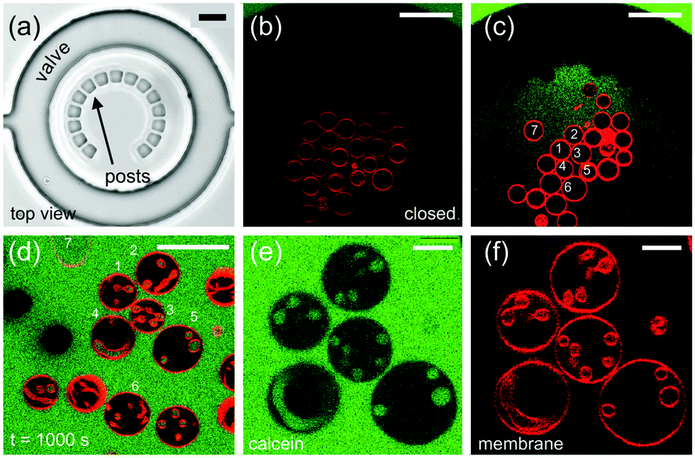 | ||
| Fig. 1 Osmotic exchange for GUVs confined in a microfluidic device. (a) Bright-field image of a single trap consisting of 15 posts arranged in a semi-circular fashion to confine multiple GUVs and still allow the free flow of fluids. The gap between neighboring posts is ≃5 μm. The ring-valve is closed to isolate the trapped vesicles from the rest of the microchannel network. (b) Confocal cross-section image of trapped GUVs prepared in 66 mM glucose. The microchannel network outside the ring-valve is filled with aqueous solution of 72 mM sugar (see main text for details) containing calcein (green). (c) As pressure is decreased from 2 bars to 0.59 bar in the upper layer, we detect non-zero fluorescence intensity of calcein inside the ring-valve indicating that the valve is open. GUVs labeled with numbers 1–7 are the same in the different panels. (d) Images showing GUVs with in-buds, in-necklaces and in-tubes after t = 1000 s from the time of opening of the valve. (e and f) GUVs with index numbers 1–5 shown as imaged in the green (calcein) and the red (membrane dye) channel. The scale bar in the images from (a–d) is 50 μm and is 10 μm for (e and f). | ||
We first characterized the trapping of the GUVs within the micro-chambers to understand the pressures they experience once they are spatially confined. We introduced 100 μl of the GUV suspension prepared in 66 mM glucose in the inlet of the microfluidic device with the ring-valves open (0 bar in the top layer). The fluid flow was driven using a syringe pump at Qfl = 0.07 μl min−1 for 20 min to load the GUVs. After about 20 min, the ring-valves were closed (2 bars in the top layer). Fig. 1b shows a confocal fluorescence image of the same compartment with the ring-valve closed after the GUVs are trapped. Initially, the concentration of sugar in the interior (Cin) and the exterior (Cex) compartment of GUVs was the same, i.e., 66 mM glucose (1.17 wt%). In the next step, we filled the microchannel network with Cex = 72 mM sugar solution composed of 9 mM sucrose (0.31 wt%) and 63 mM glucose (1.12 wt%) at a high flow rate of 25 μl min−1. Note that with the valve closed, GUVs are protected from the high flow and therefore remain trapped. The green color outside the ring-valve in Fig. 1c is due to presence of calcein that is pre-mixed in the exterior sugar solution to confirm that no leakage of calcein into the trapped region occurs when the valve is closed. Previous studies have shown that calcein does not change membrane properties when used at ∼μM concentrations.23,31 After the microchannel network is completely exchanged for the new solution, we start the continuous fluid-flow of Cex = 72 mM at 0.07 μl min−1 and release the pressure on the ring-valve incrementally in steps of 1 mbar s−1. Step-wise deflation is advantageous to minimize exposure to shear forces and a decreased flow-rate (from 25 to 0.07 μl min−1) ensures minimal loss of GUVs from the trapped region when the valve is partially open for fluid exchange at 0.59 bar. Fig. 1c shows the same compartment with trapped vesicles with the ring-valve partially open. This is a unique advantage of the valve technology such that the new solution in the vicinity of the target vesicle can be exchanged quickly and completely even with a low flow rate as the volume inside the ring-valve is approximately 0.5 nL (see Fig. S3d in ESI†). Other microfluidic techniques15,20–22 used previously do not offer this combination of possibilities.
Having large numbers of trapped vesicles allows us to preselect specific clean (without defects or leakages) and suitably sized GUVs for analysis. Note that vesicles with sizes larger than the trap height ≃20 μm were avoided because the contact of the vesicle membrane with the device walls could hinder permeation. On average, we have 7 vesicles per trap which can all be monitored in a single field of view and therefore tracked individually over time. Note that in principle tens of vesicles can be confined in each trap, but further loading was stopped to prevent significant vesicles-to-vesicle contact. The spacing between the PDMS posts allows for getting rid of smaller GUVs, which cannot be used for permeability analysis but would otherwise perturb imaging of larger vesicles. The gaps also permit efficient fluidic exchange around the GUVs. In typical deflation experiments reported in the literature, one is obliged to encapsulate in the GUV solutions which are denser (sucrose) than the one in the vesicle exterior (typically glucose). This condition makes the vesicles heavy so they sediment towards the bottom of the observation chamber and can be easily located there. The inverse condition (glucose inside and sucrose outside) is practically not accessible. To demonstrate that our microfluidic device overcomes this limitation, in our experiments the interior of vesicles was either the same or less dense than the outer solution, which would normally result in loss of vesicles floating away from the microscope objective but due to the confinement this was not an issue here.
After complete solution exchange, we observed that all GUVs develop inward tubes (cylindrical or necklace-like) and buds as shown with the vesicles (1–6) in Fig. 1d. The in-necklaces or in-tubes are filled with calcein confirming that osmotic exchange has occurred. After about 20–40 minutes of fluid exchange, in-buds remain stable for hours. Fig. 1d shows GUVs with in-buds, in-necklaces and in-tubes after t = 1000 s from the time of opening of the valve. Fig. 1e and f shows confocal cross-sections of GUVs with index number 1–5 in the green (calcein) and the red (membrane dye) channel. The presence of calcein also helps to recognize GUVs which might have ruptured or exhibited membrane pores during fluid exchange and are leaky, such as GUV no. 7. Leaky GUVs were excluded from permeability measurements. We list the pertinent experimental observations on which our analysis is based:
1. We open the valve partially for osmotic exchange. Below we consider only deflation cases but inflation can be performed as well.
2. After the fluid exchange in hypertonic solution, buds and necklaces form in the interior of the mother GUV.
3. Permeation takes place across the surface area of the mother GUV which deforms in shape due to change in vesicle volume and projected area. As a result, internal protrusions in the form of buds, tubes and necklaces are formed. The higher concentration in the vicinity of the GUV relative to internal concentration drives water through the membrane. If the deflated GUV is then exposed to hypotonic solution, we observe retraction of inward structures back to the mother GUV. Necklaces often transform into cylindrical tubes during deflation and can retract back into necklaces, during the time course of inflation as discussed in Section 3.3.
When exposed to hypertonic solution in the microfluidic chambers, the GUVs release water from inside to outside. As the fluid is exchanged between the microchannel network and the trapped region inside the ring-valve, pressure gradients are experienced by the GUV membrane. The pressure gradient due to osmotic pressure difference (ΔPos) is given by
| ΔPos(t) = ΔCRT, | (1) |
 | (2) |
3.2 Permeability data analysis and model fitting
To assess the membrane permeability, we acquire confocal 3D stacks and 2D time-series scans for individual GUVs. Fig. 2a shows a mother GUV before deflation and the same GUV after deflation is shown in Fig. 2b and c. After deflation, the GUV has an in-tube. We denote the total surface-area and volume of the GUV as Atot = (Aout + Ainv) and Vtot = (Vout − Vinv) respectively where (Vinv, Ainv) indicate volume and area of the invagination (an in-tube in Fig. 2b) and (Vout, Aout) indicate volume and area as defined by the outer vesicle contour in the images. Clearly, before deflation, Atot = Aout and Vtot = Vout as the GUV has no invaginations.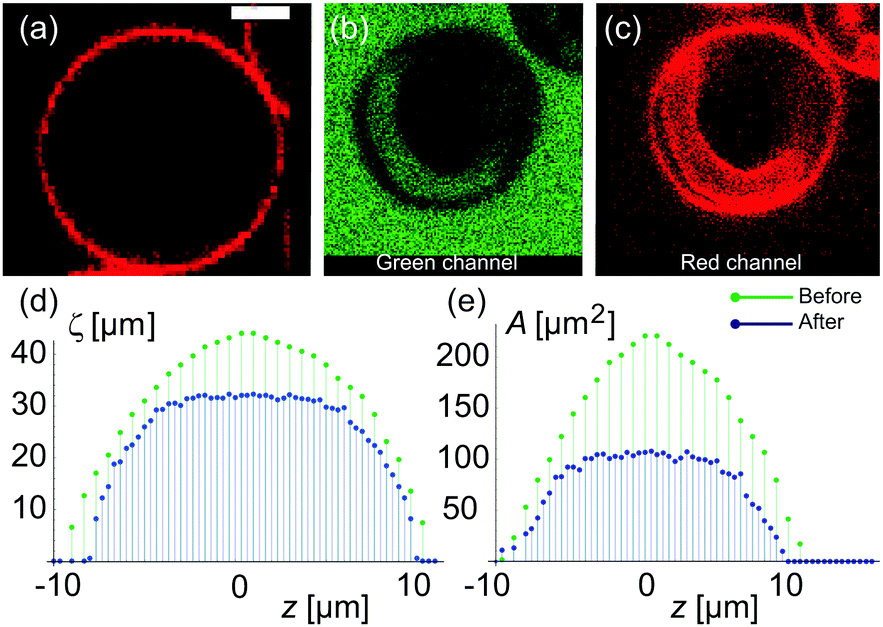 | ||
| Fig. 2 Variation of cross-sectional surface-area and cross-section circumference from one GUV pole, through the equator to the other pole. (a) An equatorial confocal cross section of a GUV before deflation and (b and c) after deflation as imaged in the green (calcein) and the red (membrane dye) channel. The green color in the in-tube is due to calcein present in the exterior sugar solution confirming that formation of the in-tube is the result of vesicle deflation. (d and e) 2D cross-sectional circumference (ζsecout) and 2D cross-sectional area (Asecout) of the same GUV as a function of vertical z-height (distance from vesicle equator) are plotted for the mother GUV before (green) and after (blue) deflation. The maximum values of (ζsecout) and (Asecout) are larger in the non-deflated state as compared to the deflated state of GUV, indicating osmotic shrinkage. The scale bar is 5 μm and applies to all images. | ||
Confocal 3D scans give accurate information about volume and surface-area provided the GUVs (and the invaginations) are not undergoing dynamic shape transformation during the time of image acquisition. Fig. 2d and e shows plots of the 2D cross-sectional circumference (ζsecout) and 2D cross-sectional area (Asecout) of the same GUV before (green data) and after (blue data) deflation as a function of vertical z-height. The magnitude of (ζsecout, Asecout) increases from the poles |z| > 10 μm towards the equator z = 0 where it reaches a maximum value. We estimate  as the integrated area under the cross-sectional circumference curve shown in Fig. 2d and
 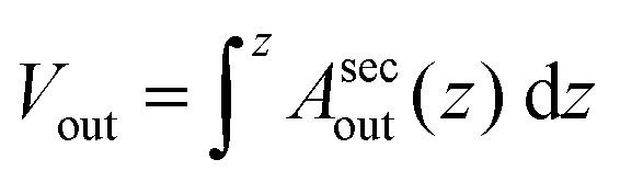 as the integrated area under the cross-sectional area curve shown in Fig. 2e. Note that this approach for calculating the vesicle area does not involve assumptions for sphericity or symmetry of the GUV as required in other studies based on transmission microscopy.10,12
From the plots shown in Fig. 2d and e we get before deflation, (Aout, Vout) ≡ (Atot, Vtot) ≃ (1300 μm2, 4500 μm3) with diameter of GUV ≃ 20.5 μm. The measurement error in the area is 25% and in the volume is 33% set by the low z-resolution of confocal microscopy. Movie S1 in the ESI† shows confocal z-scans of the GUV to appreciate that measurement error is limited by random movement of inner tube and mother vesicle during acquisition. After deflation, we get the value of (Aout, Vout) = (1103.8 ± 200 μm2, 3400.9 ± 1000 μm3) with length of the inner tube ≃18 μm and diameter ≃4 μm. It is important to note that the total surface area of the GUVs including the area of the invaginations change suggesting that area stored in membrane fluctuations contributes, and assuming a constant surface-area Atot is not very accurate. Therefore, we use the variable ![[v with combining macron]](https://www.rsc.org/images/entities/i_char_0076_0304.gif) (t) = Vtot/Atot as the volume to surface-area ratio of the mother GUV over time to quantify water permeability from the precise values of (Vout, Vinv, Aout, Ainv).
(t) = Vtot/Atot as the volume to surface-area ratio of the mother GUV over time to quantify water permeability from the precise values of (Vout, Vinv, Aout, Ainv).
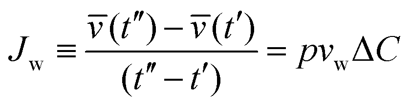
Upon exchange of the external media with a hypertonic solution, osmotic gradients at time t across the membrane are created, which results in permeation of water across the GUV membrane, measured by the permeability coefficient p. The volume flux Jw per unit area of the membrane per unit time is:
 | (3) |
.
(t) with t to estimate the permeability coefficient p shown in the inset as estimated for 7 different GUVs. We obtain an average value of p = 20.8 ± 4.5 μm s−1 where the error is the standard deviation from the mean. This permeability value is not very far from literature data, but one has to take this result with a pinch of salt because of the assumption that ΔC is constant; in the following section we will demonstrate the error associated with this assumption. In most experiments both Cin and Cex vary. While the variation in Cin can be taken into account considering the vesicles as ideal osmotic sacks, i.e. Cin(t) = Cin(0)Vtot(0)/Vtot(t), the changes in Cex (resulting from incomplete mixing) are not straightforward to estimate. Thus, we have explored a procedure to perform independent measurement of concentration Cex in the vicinity of GUVs.
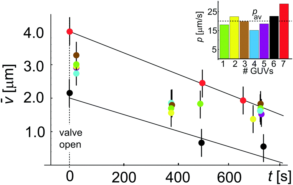 | ||
| Fig. 3 Permeability coefficient using the conventional approach, eqn (3), assuming constant ΔC. Plot showing (t) = Vtot(t)/Atot changing during deflation with time t. Data with different colors correspond to different vesicles. Error propagation analysis for gives an error of 41%. The two linear fits to the data for two GUVs (red and black) give p = 29.1 μm s−1 and p = 22.6 μm s−1. In the inset we show the obtained permeability for all 7 GUVs which yields an average value pav = 20.8 ± 4.5 μm s−1 where the error is the standard deviation from the mean. | ||
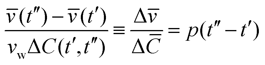
Fig. 4a shows Cex data points (green color) assessed from calcein fluorescence in the vicinity of a GUV. Under the applied flow rate (0.07 μl min−1), the time dependence of the calcein concentration is flow-dominated and not diffusion-limited and displays the concentration dependence of the sugar osmolytes used here. The fluid inside the trap is exchanged from 92 mM to 117 mM. Cex around the GUV has a unique value at a time t for a given Cin which is required to estimate ΔC(t′,t′′) = |Cex(t′′) − Cin(t′)|. As both (t) and Cin(t) depend on Vtot(t), we rewrite eqn (3) as
 | (4) |
![[C with combining macron]](https://www.rsc.org/images/entities/i_char_0043_0304.gif) = vwΔC is the dimensionless concentration difference. We have assessed the concentration of sugar inside the GUV, Cin (red data), at any given time from the total volume of the GUV and plot it together with Cex, see Fig. 4a. For a considered time interval (t′′ − t′), we show the corresponding values of in Fig. 4b for the same GUV. Fig. 5a shows plot of Δ/Δ defined in eqn (4) as a function of Δt = (t′′ − t′). The fit to all data yields p = 12.5 μm s−1 but this way of analysis gives more weight to outliers. We thus proceeded with averaging at different Δt: Fig. 5b shows an average value of the permeability coefficient estimated at different Δt where the error is the standard deviation from the mean. From this plot we get an average value of p = 15.7 ± 5.5 μm s−1. Taking into account that with this approach we use the precise local concentration of solutes in the immediate vicinity of the vesicle, we consider this approach more accurate compared to the conventional one presented in Section 3.2.1. Considering the measurement error, the conventional approach, even though not precise, could still be employed to roughly assess the permeability if no way of determining the local solute concentration is available.
= vwΔC is the dimensionless concentration difference. We have assessed the concentration of sugar inside the GUV, Cin (red data), at any given time from the total volume of the GUV and plot it together with Cex, see Fig. 4a. For a considered time interval (t′′ − t′), we show the corresponding values of in Fig. 4b for the same GUV. Fig. 5a shows plot of Δ/Δ defined in eqn (4) as a function of Δt = (t′′ − t′). The fit to all data yields p = 12.5 μm s−1 but this way of analysis gives more weight to outliers. We thus proceeded with averaging at different Δt: Fig. 5b shows an average value of the permeability coefficient estimated at different Δt where the error is the standard deviation from the mean. From this plot we get an average value of p = 15.7 ± 5.5 μm s−1. Taking into account that with this approach we use the precise local concentration of solutes in the immediate vicinity of the vesicle, we consider this approach more accurate compared to the conventional one presented in Section 3.2.1. Considering the measurement error, the conventional approach, even though not precise, could still be employed to roughly assess the permeability if no way of determining the local solute concentration is available.
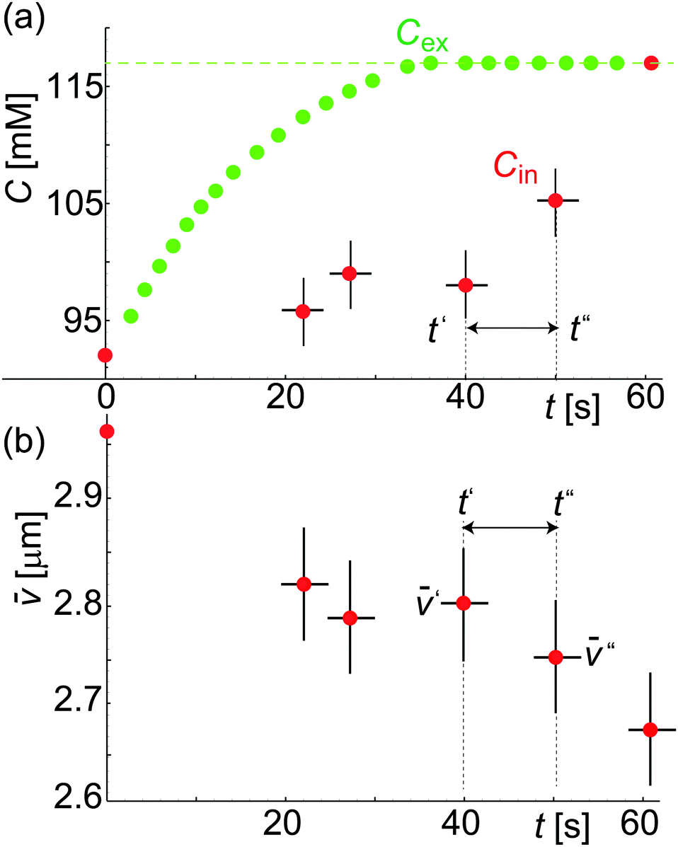 | ||
| Fig. 4 Concentration and volume/area measurements on a single GUV. (a) Plot showing Cex(t) (green) assessed from calcein intensity and Cin(t) (red) assessed from GUV volume during solvent exchange. (b) Plot showing (t) = Vtot(t)/Atot during deflation over time t. | ||
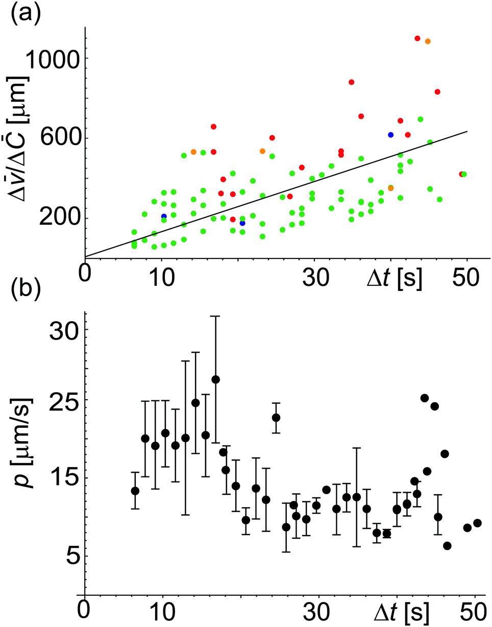 | ||
| Fig. 5 Permeability coefficient using eqn (4). (a) Values of Δ/Δ versus Δt for different vesicles (represented by different colors). The straight line fit gives p = 12.5 μm s−1. (b) Plot showing p estimated for different Δt. From the average over all the data we get p = 15.7 ± 5.5 μm s−1 where the error is the standard deviation from the mean. This way of analyzing the data prevents giving weight to outliers as occurring in the analysis in panel (a). | ||
3.3 Tube-to-necklace shape transformation and reversibility
Contrary to measurements in the bulk or with micropipettes,8,18,19 the microfluidic device allows long-term observations of single vesicles whereby inflation and deflation steps could be consecutively applied to the same vesicle. We confirmed the process reversibility, see Fig. S4 (ESI†) where the GUV was exposed to two deflation/inflation cycles. We also studied the morphological stability of invaginations in individual vesicles subjected to osmotic exchange. Fig. 6a shows a confocal cross-section of a GUV prepared in sucrose at concentration 54 mM (1.81 wt%) and thereafter deflated with aqueous solution of glucose and sucrose outside at concentration 60 mM (composed of 0.03 wt% glucose and 1.94 wt% sucrose). We observed the formation of a single in-tube shown in Fig. 6b upon deflation. The in-tube remained stable for a long time, shown in Fig. 6c and d up to t′ = 72 min. The diameter of the in-tube was not clearly detected due to its fast random movement (resulting from thermal fluctuations and not fluid flow). After about t′ = 72 min, we exchanged the exterior solution at 0.07 μl min−1 with 51 mM sucrose (1.71 wt%) and the length of the in-tube was observed to decrease with time. Confocal images shown in Fig. 6d–p were acquired with ring-valve at 0.5 bar allowing continuous fluid exchange. The GUV was confined between neighboring GUVs preventing it from moving randomly, however the in-tube was very dynamic and out of focus for t′ < 91 min. During this period, we observed retraction of the in-tube and shape transformation into an in-necklace, that has been suggested previously.38 We have tracked the number and size of the in-buds from t ≥ 0 (or t′ = 91 min) up to 196.8 s. The in-tube was composed of 6 interconnected buds at t′ = 91 min (labeled as t = 0 in the Fig. 6e) and the number of in-buds was reduced to 5 only for t > 49.02 s. The ratio of volume to surface area showed a substantial increase only between 49.02 < t < 108.8 s, as discussed in Fig. 7.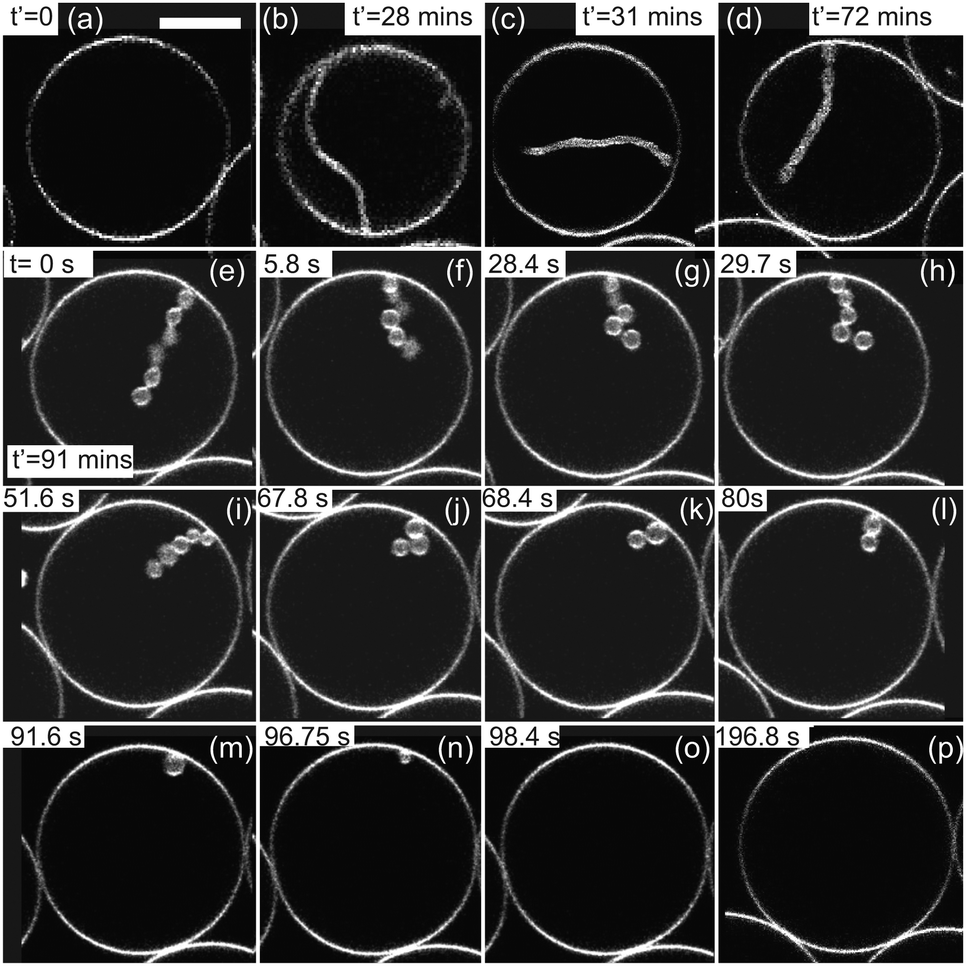 | ||
| Fig. 6 Stability of invaginations. Time sequence of gray scale, confocal cross-sections of a GUV prepared in 54 mM sucrose, deflated and inflated with time. The time for each snapshot is indicated on each frame. (a) GUV in isotonic solution: inside and outside 54 mM sucrose at t′ = 0. (b) At (t′ > 0), the GUV undergoes deflation in 60 mM sugar solution and fluid exchange is continued for t′ = 12 min. (c and d) The in-tube remains stable up to t′ = 72 min. At t′ = 72 min we start to inflate the GUV in 51 mM sucrose and fluid exchange is continued for 12 min. (e) We clearly see shape transformation of in-tube to in-necklace with 6 interconnected buds at t′ = 91 min (labeled as t = 0). (f–p) Shape transformation of the GUV showing decrease in the length of the in-necklace. The number of in-buds is reduced to 5 only at t = 50 s, and more afterwards. The scale bar of 10 μm applies to all images. | ||
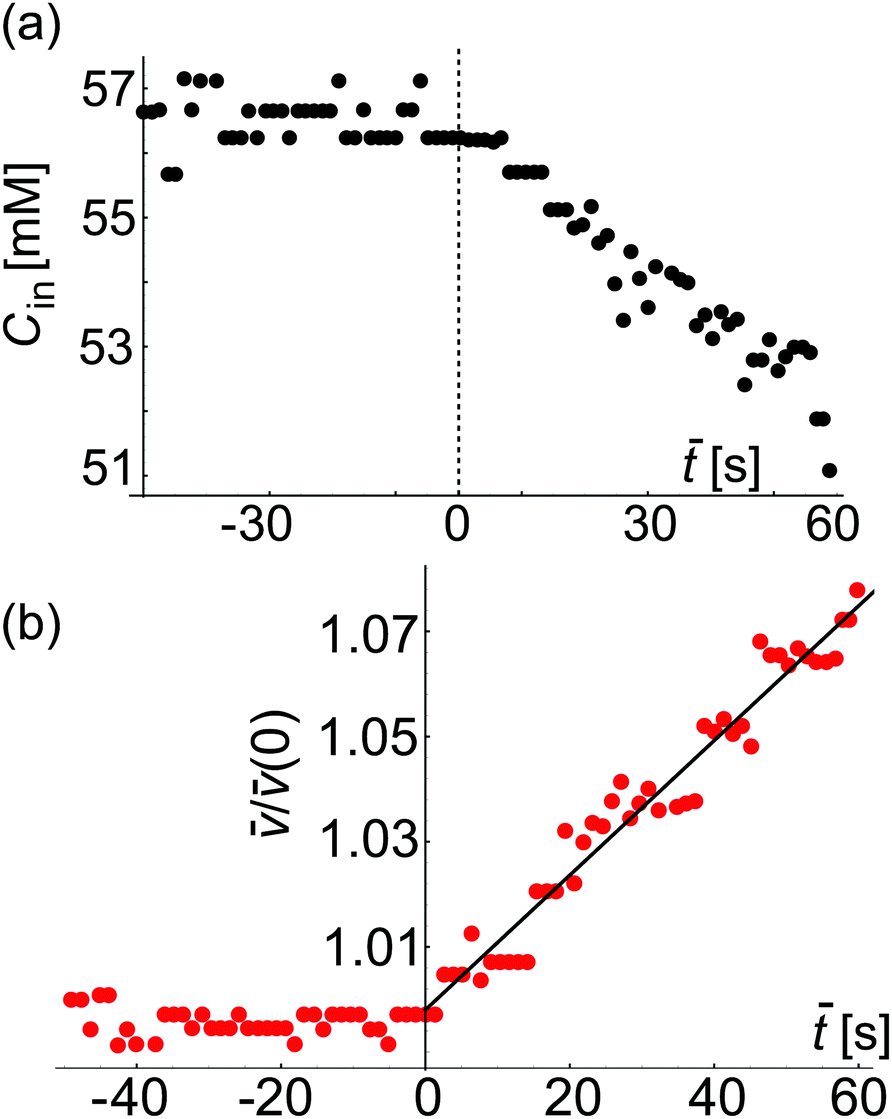 | ||
Fig. 7 Approximate estimate for the sucrose concentration inside a GUV as assessed from confocal cross sections (see text for details) and permeability measurement. (a) Plot of the instantaneous concentration Cin(![[t with combining macron]](https://www.rsc.org/images/entities/i_char_0074_0304.gif) ) inside a GUV (shown in Fig. 6). The dashed red vertical line at = 0 corresponds to t = 49.02 s in Fig. 6e where in-necklace still has 6 interconnected buds. (b) Plot of (t)/(0) with time (). From the fit using eqn (3) we obtain the apparent value p = 32.01 μm s−1, which represents an overestimate resulting from the imprecise volume estimate from 2D scans. ) inside a GUV (shown in Fig. 6). The dashed red vertical line at = 0 corresponds to t = 49.02 s in Fig. 6e where in-necklace still has 6 interconnected buds. (b) Plot of (t)/(0) with time (). From the fit using eqn (3) we obtain the apparent value p = 32.01 μm s−1, which represents an overestimate resulting from the imprecise volume estimate from 2D scans. | ||
Image analysis of these recordings could be used to measure the volume and surface-area of the GUV, providing a second (albeit less accurate) approach for deducing the membrane permeability to water. Because of the dynamic behavior of the in-necklace, we were not able to collect 3D images. Instead, the vesicle volume and surface-area were roughly assessed from the 2D-confocal time series. From them, we calculated the concentration of sucrose inside the GUV shown in Fig. 7a where = (t − 49.02) s. In these experiments, no calcein was added in the external solution and we do not have precise information about the external concentration. Thus, in this case as a rough approximation, we assume ΔC as constant and use eqn (3). Fig. 7b shows the plot of (t)/(t = 0) (see eqn (3)) of this GUV during inflation against time ().
We find that both Cin() and (t)/(0) do not change for < 0. We then fit eqn (3) to the data for the time period ≥ 0 and find p = 32.01 μm s−1. We could estimate (t) precisely from the 3D confocal stacks acquired only at = 60 s but for < 60 s, we have used the 2D-confocal time series, which results in less precise estimate for the membrane permeability. This apparent permeability is higher than the one reported in Fig. 4 and 5 and results from the imprecise volume estimates assessed from the 2D images. The overestimate of the permeability is particularly pronounced for GUVs of equatorial diameter larger than the height of the microfluidic chip. In the latter case, the vesicles are deformed (squeezed) while the image analysis assumes a spherical shape with overestimated diameter.
3.4 Limitations: dynamics of GUVs in confinement
In Section 3.1 we have shown that for all experiments reported in this paper, the pressure gradient caused by the flow is small, ΔPfl ≪ ΔPos. However, at a fluid flow rate of Qfl = 0.07 μl min−1 with the ring-valves open, we occasionally observe that some GUVs are moved by the flow while undergoing osmotic exchange. The application of controlled flow in the microfluidic chamber and studying the response of GUV membranes is an exciting research field to understand membrane hydrodynamics.26–28,37 In this section, we summarize our experimental observations on various motions of GUVs during osmotic exchange and fluid flow in the microfluidic chamber that can give misleading values of permeability and as such these GUVs were avoided for the permeability measurements. Fig. 8a shows the top view of GUV exhibiting elongation and rotation reminiscent of vesicle tumbling.39Fig. 8b shows the schematic for the same rotation. Clearly, we cannot use such a GUV to assess the membrane permeability because extracting the exact values of Vtot and Atot from the confocal 3D stacks will be non-trivial. | ||
| Fig. 8 Motion of GUVs revealed by confocal cross-sections in gray scale and schematics. (a) Cross-sections of a rotating GUV exhibiting tumbling-like dynamics. (b) Schematics of the GUV deformation and rotation shown in panel (a). (c and d) Cross-section images and sketches of a GUV with an in-necklace held between two PDMS posts (drawn in red) shows tank-treading (TT) motion where lateral displacement of the in-necklace is observed within the GUV. ϕ is the angle between the long axis of in-necklace and the horizontal axis. (e and f) Images and sketches of a GUV with in-necklace held between two posts (drawn in red) showing TT motion as well as retraction of the in-necklace into the mother GUV resulting in an increase of the length of the tongue of the mother GUV between posts. When the mother GUV moves away and is no longer restricted between the posts, an in-necklace forms again. The scale bar is 20 μm for all images. | ||
Fig. 8c shows a GUV that is held by two PDMS posts and exhibits tank-treading (TT) motion.26,34,35 This can be easily detected by following the movement of an in-necklace relative to its orientation inside the GUV. It is possible to characterize the angle ϕ that measures the displacement of an in-necklace relative to the vesicle axis and varies in multiples of 2π with time. The length of in-necklaces can also change during TT motion. The corresponding schematic is shown in Fig. 8d. We do not observe any passive movement of vesicles in concentration gradients, e.g. diffusiophoresis.40–42
Fig. 8e shows an initially free GUV with in-necklaces. The GUV undergoes TT motion and retraction of the in-necklace into the mother GUV after its movement is halted by two posts. The corresponding schematic is shown in Fig. 8f. The decrease in the length of in-necklace results in an increase in the tongue of the mother GUV protruding between the posts, up to nearly full-retraction of the in-necklace. The in-necklace forms again after the GUV drifts away from the post. Clearly, the length of the tongue of the GUV between posts will depend on the excess membrane area of the vesicle, the membrane area of in-necklace, the gap between the posts and on the volume flow rate. We can not use a TT-GUV for permeability measurements because the membrane area stored in the in-necklace is changing during the motion. In addition, acquiring confocal 3D stacks of such a GUV will not give meaningful information about Vtot and Atot. However, the above examples demonstrate the ability of using our microfluidic chambers for studying rotation and tank-treading of vesicles.
4 Conclusions
The experiments reported in this paper utilizing microfluidic technology show that when subjected to an osmotic deflation by external fluid exchange with a hypertonic sugar solution GUVs display the formation of in-buds, in-necklaces and in-tubes. These measurements of morphological transitions on single vesicles were enabled due to microfluidic trapping and complete fluid exchange. The results indicate that as the water-flux across the bilayer membrane created by osmotic gradients induces shape changes of the GUV membrane, it is indeed possible to measure the permeability coefficient p knowing the vesicle volume and surface-area at a given instant of time. Knowing Vtot and Atot also enables us to determine the vesicle reduced volume during fluid exchange.Our device uses integrated ring-valves surrounding GUV traps which gives additional advantages not only compared to traditional methods (micropipettes, bulk mixing, etc.) but also compared to previous microfluidic solutions. The first is that each valve isolates and traps a sub-set of the trapped GUVs and therefore permits up to 6 independent experiments per chip. This can either be used for separate experiments (i.e. deflation or inflation or sugar exchange) or repetitions for increased statistics. Each trap is also able to capture multiple GUVs which further increases the experimental throughput in handling them. The second advantage is that the GUVs remain spatially confined even during fluidic exchange which therefore allows them to be monitored for long time periods. We use this for real-time observations of the morphological changes that occur after solution exchange to the final desired concentration. Furthermore, sequential inflation–deflation steps can be performed on the same vesicle. By partially opening the valves, the fluidic exchange is fast, complete, and homogenous all with minimum shear forces allowing the GUV shapes to evolve freely. Finally, the small height of the microfluidic channels (20 μm) prevents light vesicles from floating up thus removing the requirement of working with heavier vesicles (which imposes conditions on the working external and internal solutions).
Previous experiments reported in the literature to measure permeability have limitations and require: (1) very good optical contrast that is usually created by a heavier sugar in the GUV interior and a lighter sugar in the GUV exterior leading to sedimentation of GUVs on the bottom coverslip, (2) long-time imaging which is achieved either by sedimentation of GUVs or by holding the GUVs in a micropipette or by anchoring the GUVs to minimize movement.12,18 Micropipette aspiration allows the measurement of permeability on the same GUV before and after deflation but part of the GUV aspirated inside the micropipette capillary is not directly exposed to the exterior sugar solution. Our microfluidic approach ensures that the entire outer membrane is exposed to the new solution simultaneously which simplifies the analysis. Not only this but the combination of traps and valves allows us to precisely control the concentration gradients in both space and time. We also independently measure the local external concentration in the vicinity of vesicles getting rid of mixing artifacts and assessing the concentration gradient more precisely.
The significant advantage of our approach compared to the previous work (except for micropipette aspiration approaches8) is that we have exact knowledge available regarding the vesicle shape (area and volume). Observations conducted with phase contrast microscopy lack the possibility of (i) distinguishing spherical from oblate vesicles, and (ii) detecting membrane protrusions. Both of these reflect in large uncertainties in determining the area and volume of the vesicles. We overcome this difficulty using confocal imaging of the vesicles. As a result, we can claim that our approach can be applied also to vesicles with asymmetric membranes the deflation of which could result in storing the excess area in tubes or buds. Previously, shape changes of GUV of same lipid composition due to sugar asymmetry has been reported43 for the measurement of spontaneous tension. Any change in membrane composition due to intrinsic lipids or solvent composition around the membrane can have an effect on membrane permeability.44–46
For the sake of clarity, we analysed vesicles using the conventional approach which assumes constant concentration gradient across the membrane, see Section 3.2.1 and Fig. 3. The resulting permeability is slightly off but still comparable (within the error) to the one obtained from the exact approach, which takes into account the precise solute concentration in the vesicle vicinity, Section 3.2.2 and Fig. 5b. Even less precise in the result for the permeability assessed from cross-sectional images and not from 3D imaging of the vesicles (Section 3.4 and Fig. 7b), pointing to the importance of precise knowledge of the vesicle shape which is offered from confocal microscopy but not from transmission imaging (i.e. bright field and phase contrast).
The obtained permeability values (p = 15.7 ± 5.5 μm s−1) for GUVs with membrane composition of POPC/chol (10 mol%) is consistent within the error with previously reported values for the binary lipid mixture of PC lipids with cholesterol.11,12,19,47 Previous measurements of permeability report a value of 15.3 ± 3.4 μm s−1 for DOPG/chol (20%) and 6.6 ± 1.5 μm s−1 for DOPG/chol (40%).12 Considering that permeability is increased with decreasing the amount of cholesterol and has a value 28 ± 6 μm s−1 for SOPC, 42 ± 6 μm s−1 for DOPC,19 our measurements are consistent with these data. The fact that the microfluidic device can be applied to deducing the membrane permeability as well as the demonstrated feasibility for observing and characterizing vesicle rotation and tank-treading opens the possibility of further applications of the technology. The approach we have presented here can be potentially used for routine permeability characterization of lipid GUVs, as demonstrated here, but also of polymersomes.48 It should be applicable also to studying vesicles prepared with phase-transfer or emulsion-based techniques where oil can remain trapped into the membrane (see e.g.ref. 49) thus affecting permeability to water.
Conflicts of interest
There are no conflicts to declare.Acknowledgements
This work was supported by the MaxSynBio consortium, which was jointly funded by the Federal Ministry of Education and Research of Germany (BMBF) and the Max Planck Society (MPG). TB acknowledges R. Lipowsky for useful discussions, and T. Seeman and J. Wienke for technical help with the microfluidic chips. Open Access funding provided by the Max Planck Society.References
- P. Walde, K. Cosentino, H. Engel and P. Stano, ChemBioChem, 2010, 11, 848–865 CrossRef CAS PubMed.
- R. Dimova, Annu. Rev. Biophys., 2019, 48, 93–119 CrossRef CAS PubMed.
- R. Dimova, S. Aranda, N. Bezlyepkina, V. Nikolov, K. A. Riske and R. Lipowsky, J. Phys.: Condens. Matter, 2006, 18, S1151–S1176 CrossRef CAS PubMed.
- R. Dimova and C. Marques, The Giant Vesicle Book, Taylor and Francis Group, LLC, Boca Raton, 2019 Search PubMed.
- G. P. Lidgard and M. N. Jones, J. Membr. Biol., 1975, 21, 1–10 CrossRef CAS PubMed.
- K. I. Inui, K. Tabara, R. Hori, A. Kaneda and S. Muranishi, J. Pharm. Pharmacol., 1977, 29, 22–26 CrossRef CAS PubMed.
- P. Cao and D. P. Raleigh, Methods Mol. Biol., 2016, 1345, 283–290 CrossRef CAS PubMed.
- K. Olbrich, W. Rawicz, D. Needham and E. Evans, Biophys. J., 2000, 79, 321–327 CrossRef CAS PubMed.
- P. Peterlin, G. Jaklič and T. Pisanski, Meas. Sci. Technol., 2009, 20, 055801 CrossRef.
- E. Boroske, M. Elwenspoek and W. Helfrich, Biophys. J., 1981, 34, 95–109 CrossRef CAS PubMed.
- A. L. Bernard, M. A. Guedeau-Boudeville, L. Jullien and J. M. di Meglio, Biochim. Biophys. Acta, Biomembr., 2002, 1567, 1–5 CrossRef CAS.
- M. M. A. E. Claessens, F. A. M. Leermakers, F. A. Hoekstra and M. A. C. Stuart, Biochim. Biophys. Acta, Biomembr., 2008, 1778, 890–895 CrossRef CAS PubMed.
- P. Peterlin, V. Arrigler, E. Haleva and H. Diamant, Soft Matter, 2012, 8, 2185–2193 RSC.
- S. Li, P. Hu and N. Malmstadt, Anal. Chem., 2010, 82, 7766–7771 CrossRef CAS PubMed.
- S. Li, P. Hu and N. Malmstadt, Biophys. J., 2011, 101, 700–708 CrossRef CAS PubMed.
- T. Robinson and P. S. Dittrich, ChemBioChem, 2019, 20, 2666–2673 CrossRef CAS PubMed.
- K. Nishimura, T. Matsuura, T. Sunami, S. Fujii, K. Nishimura, H. Suzuki and T. Yomo, RSC Adv., 2014, 4, 35224–35232 RSC.
- V. Vitkova, J. Genova and I. Bivas, Eur. Biophys. J., 2004, 33, 706–714 CrossRef CAS PubMed.
- W. Rawicz, B. A. Smith, T. J. McIntosh, S. A. Simon and E. Evans, Biophys. J., 2008, 94, 4725–4736 CrossRef CAS PubMed.
- H. Nuss, C. Chevallard, P. Guenouna and F. Malloggia, Lab Chip, 2012, 12, 5257–5261 RSC.
- A. Yamada, S. Lee, P. Bassereau and C. N. Baroud, Soft Matter, 2014, 10, 5878–5885 RSC.
- S. Vrhovec, M. Mally, B. Kavcic and J. Derganc, Lab Chip, 2011, 11, 4200–4206 RSC.
- T. Robinson, P. Kuhn, K. Eyer and P. S. Dietrich, Biomicrofluidics, 2013, 7, 044105 CrossRef CAS PubMed.
- B. Kubsch, T. Robinson, R. Lipowsky and R. Dimova, Biophys. J., 2016, 110, 2581–2584 CrossRef CAS PubMed.
- L. Miao, U. Seifert, M. Wortis and H. Döbereiner, Phys. Rev. E: Stat. Phys., Plasmas, Fluids, Relat. Interdiscip. Top., 1994, 49, 5389 CrossRef CAS PubMed.
- D. Abreua, M. Levant, V. Steinberg and U. Seifert, Adv. Colloid Interface Sci., 2014, 208, 129–141 CrossRef PubMed.
- M. Levant and V. Steinberg, Phys. Rev. Lett., 2014, 112, 138106 CrossRef PubMed.
- A. Pommella, N. J. Brooks, J. M. Seddon and V. Garbin, Sci. Rep., 2015, 5, 13163 CrossRef CAS PubMed.
- M. Angelova, S. Soléau, P. Méléard, F. Faucon and P. Bothorel, Trends in Colloid and Interface Science VI, Springer, Berlin/Heidelberg, 89th edn, 1992 Search PubMed.
- N. Yandrapalli, T. Seemann and T. Robinson, Micromachines, 2020, 11, E285 CrossRef PubMed.
- N. Yandrapalli and T. Robinson, Lab Chip, 2019, 19, 626–633 RSC.
- H. A. Stone, in Introduction to Fluid Dynamics for Microfluidic Flows, ed. H. Lee, R. M. Westervelt and D. Ham, Springer US, Boston, MA, 2007, pp. 5–30 Search PubMed.
- V. R. N. Telis, J. Telis-Romero, H. B. Mazzotti and A. L. Gabas, Int. J. Food Prop., 2007, 10, 185–195 CrossRef CAS.
- M. Abkarian, C. Lartigue and A. Viallat, Phys. Rev. Lett., 2002, 88, 068103 CrossRef PubMed.
- V. Kantsler and V. Steinberg, Phys. Rev. Lett., 2005, 95, 258101 CrossRef PubMed.
- H. Noguchi and G. Gompper, Phys. Rev. Lett., 2007, 98, 128103 CrossRef PubMed.
- V. Steinberg and M. Levant, in The Giant Vesicle Book, ed. R. Dimova and C. Marques, Taylor and Francis Group, LLC, Boca Raton, 2019, pp. 417–435 Search PubMed.
- Y. Liu, J. A. Canelejo, A. Grafmueller, R. Dimova and R. Lipowsky, ACS Nano, 2016, 10, 463 CrossRef CAS PubMed.
- V. Kantsler and V. Steinberg, Phys. Rev. Lett., 2006, 96, 036001 CrossRef PubMed.
- A. Kodama, Y. Sakuma, M. Imai, Y. Oya, T. Kaeakatsu, N. Puff and M. I. Angelova, Soft Matter, 2016, 12, 2877–2886 RSC.
- M. M. Manni, M. L. Tiberti, S. Pagnotta, H. Barelli, R. Gautier and B. Antonny, eLife, 2018, 7, e34394 CrossRef PubMed.
- S. V. Hartman, B. Bozic and J. Derganc, New Biotechnol., 2018, 47, 60–66 CrossRef PubMed.
- T. Bhatia, S. Christ, J. Steinkühler, R. Dimova and R. Lipowsky, Soft Matter, 2020, 16, 1246–1258 RSC.
- S. J. Marrink and H. J. C. Berendsen, J. Phys. Chem., 1994, 98, 4155–4168 CrossRef CAS.
- J. Baykal-Caglar, E. Hassan-Zadeh, B. Saremi and J. Huang, Biochim. Biophys. Acta, Biomembr., 2012, 1818, 2598–2604 CrossRef PubMed.
- E. Elizondo, J. Larsen, N. S. Hatzakis, I. Cabrera, T. Bjørnholm, J. Veciana, D. Stamou and N. Ventosa, J. Am. Chem. Soc., 2012, 134, 1918–1921 CrossRef CAS PubMed.
- B. Ugarte-Uribe, A. J. García-Sáez and M. M. A. E. Claessens, in The Giant Vesicle Book, ed. R. Dimova and C. Marques, Taylor and Francis Group, LLC, Boca Raton, 2019, pp. 437–451 Search PubMed.
- B. M. Discher, Y. Y. Won, D. S. Ege, J. C. M. Lee, F. S. Bates, D. E. Discher and D. A. Hammer, Science, 1999, 284, 1143–1146 CrossRef CAS PubMed.
- N.-N. Deng, M. Yelleswarapu and W. T. S. Huck, J. Am. Chem. Soc., 2016, 138, 7584–7591 CrossRef CAS PubMed.
Footnote |
| † Electronic supplementary information (ESI) available. See DOI: 10.1039/d0sm00155d |
| This journal is © The Royal Society of Chemistry 2020 |