
Measuring viscoelasticity of soft biological samples using atomic force microscopy
Yuri M.
Efremov
 *abc,
Takaharu
Okajima
d and
Arvind
Raman
ab
*abc,
Takaharu
Okajima
d and
Arvind
Raman
ab
aSchool of Mechanical Engineering, Purdue University, West Lafayette, Indiana, USA. E-mail: yu.efremov@gmail.com
bBirck Nanotechnology Center, Purdue University, West Lafayette, Indiana, USA
cInstitute for Regenerative Medicine, Sechenov University, Moscow, Russia
dGraduate School of Information Science and Technology, Hokkaido University, Sapporo, Japan
First published on 12th November 2019
Abstract
Mechanical properties play important roles at different scales in biology. At the level of a single cell, the mechanical properties mediate mechanosensing and mechanotransduction, while at the tissue and organ levels, changes in mechanical properties are closely connected to disease and physiological processes. Over the past three decades, atomic force microscopy (AFM) has become one of the most widely used tools in the mechanical characterization of soft samples, ranging from molecules, cell organoids and cells to whole tissue. AFM methods can be used to quantify both elastic and viscoelastic properties, and significant recent developments in the latter have been enabled by the introduction of new techniques and models for data analysis. Here, we review AFM techniques developed in recent years for examining the viscoelastic properties of cells and soft gels, describe the main steps in typical data acquisition and analysis protocols, and discuss relevant viscoelastic models and how these have been used to characterize the specific features of cellular and other biological samples. We also discuss recent trends and potential directions for this field.
1. Introduction
The mechanical properties of cells, biological tissues, and artificial tissue-mimicking matrices have been found to be critical in physiological and pathological processes such as differentiation, transformation, and regeneration.1–4 These biological materials have complex structure at both micro- and nano-scale levels, and are generally soft, exhibiting values of Young's modulus from tens of Pa to several MPa. Owing to this, the biomechanical characterization of these materials normally requires both force and displacement at micro- and nano-scale resolutions. This challenge has been addressed by developments in biomechanical instruments, including micropipette aspiration,5,6 atomic force microscopy (AFM), optical/magnetic tweezers and stretchers,7,8 cell traction force microscopy9–11 and nanoindentation.12 In particular, nanoindentation with AFM remains one of the most popular methods for probing the nanoscale properties of soft biological samples in physiological environments.13–16AFM methods provide a variety of tools for evaluating micromechanical properties by measuring the interactions between a microcantilever probe and the specimen surface. Precise control over the force applied to the probe allows us to study a wide variety of heterogeneous biological materials. The accuracy of piezo scanners provides AFM-based methods with the unique ability to both image the sample and to study its mechanical properties in different experimental configurations. The selection of the probe (a sharp tip versus a microbead attached to the microcantilever) provides the opportunity to adjust the spatial resolution, balancing precision mapping versus the fast acquisition of averaged properties.
Since the earliest mechanical characterization experiments,17–20 it has been noticed that biological materials have unusual properties that cannot be completely described in the context of elastic (or “Hertzian”) contact. Even in the absence of active cellular responses, the behavior of biological material combines both solid- and liquid-like aspects. For such materials, also called viscoelastic, the relationship between stress and strain changes over time, giving rise to a whole range of specific phenomena. The important role of viscoelastic properties has been demonstrated in past experiments at all levels of biological organization.21–26 The viscoelastic behavior of biomaterials is thought to originate from their complex structure, involving the composition of both solid and fluid components, and the existence of structural hierarchies, active dynamics and force generation (reviewed in ref. 26–30). Special methods of characterization are required for viscoelastic (also referred to as rheological) properties, involving experiments in the time and frequency domains.
The present review is focused on the use of AFM techniques to characterize the viscoelastic properties of biological samples, and specifically animal cells. Despite the wide use of AFM for mechanical measurements of biological soft matter, the majority of prior studies use the framework of standard Hertzian contact mechanics, and thus only measure the apparent elastic modulus of the materials, disregarding viscoelastic effects. This review will help interested researchers to make a transition from a pure elastic description of the data to a viscoelastic one. We will focus on several aspects: a description of the current AFM protocols for viscoelastic measurements, data analysis and viscoelastic models, and the associated uncertainties and limitations. Although a large variety of protocols and models are available, a lack of standardization in the field of AFM-based viscoelastic characterization makes it difficult to compare data between different studies. We will also discuss trends and potential directions for future research in the field.
2. AFM setup and basics
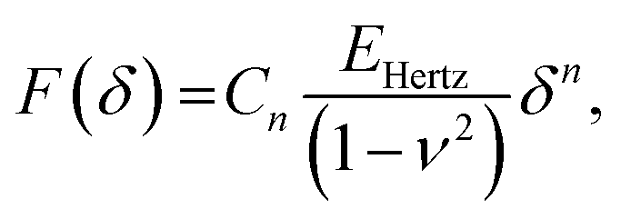
In AFM, a microcantilever is used as a force sensor to measure interactions between the probe (a sharp microcantilever tip or bead) and the sample surface (Fig. 1A). The deflection of the microcantilever deflection is measured with an optical system that involves a laser spot reflected from the microcantilever and detected by a quadrant photodiode. Piezoelectric translators allow movement of the probe relative to the sample, and are used to perform scanning and indentation experiments. While sharp microcantilever tips are usually used in scanning in order to obtain a high spatial resolution, colloidal beads (microspheres) are often preferred in indentation experiments for qualitative measurements.32–34 In a classical AFM indentation experiment, the piezo translator moves the microcantilever base toward the sample with a predefined vertical speed. At a certain point (the contact point, Z0), the microcantilever probe contacts the sample and starts to indent it until the prescribed interaction force (trigger force) is reached, and the microcantilever base is then moved upward with the same speed. The force is calculated from the microcantilever tip deflection q as F = k × q. The data from this experiment form the so-called force–displacement curve (F–Z curve, or just force curve) representing force vs. piezo displacement (Fig. 1B). These data are further processed to obtain the force vs. indentation (F–δ curve) dependency (Fig. 1C), as follows. Since the microcantilever deflects during indentation, the indentation depth is related to the scanner displacement as δ = Z − Z0 − q, where Z0 is the location of the contact point. Due to this relation, the indentation typically changes nonlinearly during the AFM experiment for a linear scanner displacement. The framework of Hertz's contact mechanics35,36 is generally used to process the AFM force curves further. These equations describe the F(δ) dependencies for different shapes of the AFM probe tip (cylinder, cone, pyramid, blunted pyramid, and an arbitrary axisymmetric shape).36,37 For example, for a spherical indenter, the original Hertz's model is traditionally used:35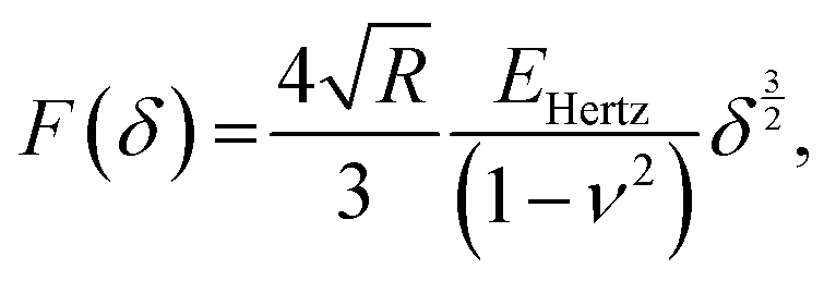 | (1) |
 | (2) |
 | (3) |
![[thin space (1/6-em)]](https://www.rsc.org/images/entities/char_2009.gif) α)/π for conical indenter (where α is the semi-included angle of the cone); n = 2 and C2 = 1.4906 × (tanα)/2 for a pyramidal indenter (where α is the semi-included angle between the faces of the pyramid40); and n = 3/2,
α)/π for conical indenter (where α is the semi-included angle of the cone); n = 2 and C2 = 1.4906 × (tanα)/2 for a pyramidal indenter (where α is the semi-included angle between the faces of the pyramid40); and n = 3/2, 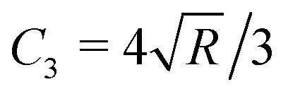 for both paraboloid and spherical indenters (where R is the radius of sphere). The probe is generally assumed to be infinitely rigid in comparison to soft samples such as cells. In Hertz's framework, the following assumptions are implied: the sample is homogeneous, isotropic, linearly elastic and sufficiently large to be approximated as an infinite half-space, and there are no attractive or adhesive forces between the sample and the probe.
 | ||
| Fig. 1 AFM basics. (A) The main elements of an AFM setup. The tip, which usually has a conical, pyramidal, spherical or cylindrical shape, interacts with the sample, and the interaction forces cause the microcantilever to deflect (bend). The deflection is monitored via a laser beam reflected from the microcantilever onto a four-quadrant photodiode. A set of piezoelectric translators allows nanometer-scale movement of the microcantilever with respect to the sample. In a typical AFM indentation experiment, the microcantilever base moves with a constant vertical speed, which is the same for the approach and retraction phases, while the force is recorded. (B) Example of the F–Z curve obtained on a 3T3 fibroblast with the spherical indenter. The contact point is marked with an arrow. (C) The contact point (Z0) is usually identified as part of the post-processing of data, and the acquired F–Z curve is transformed into the force–indentation coordinates. The equivalent Young's modulus EHertz is calculated with Hertz's model. Hysteresis between the approach and retraction curves is clearly seen. Inset: Scheme of a spherical probe indenting a half-space. B and C are adapted from ref. 31, CC-BY-4.0, published by Springer Nature. | ||
The Hertz model predicts that the approach and retraction force curves coincide, and that there is no hysteresis in the indentation cycle; however, this is clearly not the case for living cells and most other biological materials. Hysteresis indicates the presence of energy dissipation during the indentation process, and the main source of hysteresis in liquid environments is the viscoelasticity of the sample. Thus, it has been suggested that the hysteresis area of the force curve can be used to estimate the viscoelastic properties of a sample in a liquid. A simple means of quantifying this hysteresis is to numerically calculate the area enclosed by the approach and retraction curves, and to divide this by the area under the approach curve.7,41,42 In this way, normalized hysteresis is obtained, i.e. the relative amount of energy lost during the indentation cycle. The apparent viscosity of the sample can be calculated numerically using additional assumptions.43 Although these parameters cannot determine the viscoelastic constitutive parameters directly, they can be useful in a comparison of different samples, since a larger hysteresis area (usually normalized by the total area under the approach curve) corresponds to a larger energy loss and viscoelastic contribution.
Solutions to the viscoelastic counterpart of Hertz's model have been presented in several works.44–46 The use of these models to extract viscoelastic properties from experiment is not straightforward. In a simple case in which the microcantilever is much stiffer than the sample, an analytical solution can be obtained for specific viscoelastic functions to fit either the complete curve (both the approach and retraction parts)47,48 or only the approach part.49 A numerical solution can be used for a more general case.31Fig. 2 shows a set of curves that are numerically constructed for materials that behave according to different viscoelastic models at different times, together with some experimental curves. Ting's viscoelastic solution captures the approach-retraction hysteresis well, but the viscoelastic function needs to be preselected for this type of analysis. Partly due to these challenges, Ting's model has only recently been applied31,48 to extract viscoelastic data directly from conventional AFM force curves.
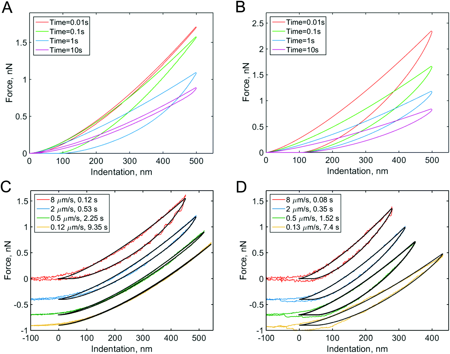 | ||
| Fig. 2 Force curves numerically modeled with Ting's model for different viscoelastic models and indentation times: (A) the standard linear solid (SLS) viscoelastic model (relaxation time τ = 0.1 s); (B) the power-law rheology (PLR) model (power-law exponent α = 0.15). The SLS model predicts most of the viscoelastic relaxation at times close to the relaxation time, as can be seen from the hysteresis area in the curves. For the PLR model, the amount of relaxation (hysteresis area) does not substantially vary with indentation time. (C) Experimental F–δ curves obtained on PAAm hydrogel and (D) NIH 3T3 fibroblast for different indentation times. The offset is added to the force for clarity. The black lines show the fits to the (C) SLS and (D) PLR models. Adapted from ref. 31, CC-BY-4.0, published by Springer Nature. | ||
In this review, we will describe the AFM techniques that have been developed in recent years to examine the viscoelastic properties of cells and soft gels in the time and frequency domains, and will describe the main steps in typical data acquisition and analysis protocols. We discuss the basic theoretical concepts of viscoelasticity in relation to the indentation experiments and review relevant viscoelastic models, showing how they might be used for specific samples and tasks.
3. Experimental techniques
A distinctive property of viscoelastic materials is the relationship between the stress and strain and the strain rate. The following phenomena can be observed in experiments with viscoelastic materials: (i) the effective (apparent) stiffness depends on the rate of application of the force (indentation speed);7,50,51 (ii) viscoelastic energy loss leads to hysteresis between the approach and retraction curves;7,41,42 (iii) if the force (stress) is held constant, the indentation (strain) increases with time (creep);52–55 (iv) if the indentation (strain) is held constant, the force (stress) decreases with time (relaxation);56–58 and (v) if cyclic loading is applied, a phase lag occurs between force and indentation.33,59 Viscoelastic (rheological) characterization of the sample with AFM can be performed based on any of these phenomena, due to the high versatility of the device (Fig. 3). On the other hand, a quantitative comparison between viscoelasticity measurements from different studies is complicated by the wide variety and lack of standardization of AFM-based techniques for viscoelasticity characterization.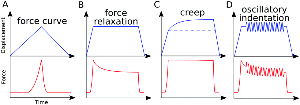 | ||
| Fig. 3 AFM protocols for measurement of viscoelastic behavior, exemplary displacement and force versus time data: (A) conventional force curve, time representation; (B) stress relaxation; (C) creep experiment; (D) oscillatory indentation (force modulation). Force modulation also can be applied over the whole indentation cycle or during scanning. | ||
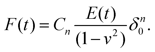
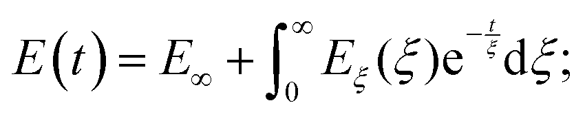
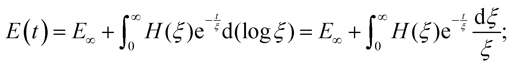
Before continuing to a description of AFM techniques for viscoelastic measurements, a few words should be said about the concept of viscoelasticity. For viscoelastic materials, a time-dependent function is used instead of a single value of Young's modulus, and this is called the Young's relaxation modulus E(t). The corresponding relaxation function for shear stress can be obtained as G(t) = E(t)/2/(1 + v). The creep compliance function J(t) is used to describe creep behavior and can be related to both the Young's modulus (JE(t)) and shear modulus (JG(t)). The Young's relaxation modulus and the creep compliance are not explicitly inverse in the time domain; however, in the Laplace domain, E(s)JE(s) = 1/s2, and in the frequency domain, E*(ω)J*E(ω) = 1 (where the “*” symbol denotes a complex quantity). A “reduced” form of the relaxation (creep) function can be obtained that represents the function normalized by its initial value: ϕ(t) = E(t)/E(0) (ψ(t) = J(t)/J(0)).
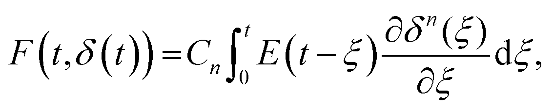
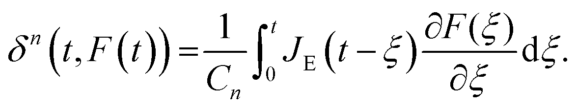
A naïve implementation of viscoelasticity would be to simply substitute Young's modulus with the Young's relaxation modulus in eqn (1). This is an incorrect approach, except in the specific case of an instantaneous load and subsequent stress relaxation (see below). When linearity is assumed, superposition should be applied to segments of the indentation (strain) history, as stated by the Boltzmann superposition principle. This gives rise to a convolution integral known as the Boltzmann hereditary integral.60,61 Moreover, for a range of viscoelastic problems, the correspondence principle states that the solution can be obtained based on the corresponding linearly elastic problem: each quantity that depends on time is replaced by its Laplace transform multiplied by the transform variable, and this is then transformed back to the time domain. Although the general indentation of the viscoelastic body presents a more complicated problem, as it has time-varying boundary conditions, Lee and Radok46 have found that the correspondence principle still works when the contact area does not decrease with time (i.e. the approach phase of the force curve and step-hold experiments):
 | (4) |
 | (5) |
Although cases with a decreasing (retraction part of the force curve) or non-monotonically changing contact area are more complicated, solutions were found in subsequent works, with Ting's solution being one of these.44,45 Both the Lee–Radok and Ting solutions can be applied to the processing of indentation data, as shown in the next section.
The versatility of AFM comes from its ability to precisely measure and control force (∼stress) and indentation (∼strain), meaning that a large variety of experimental protocols can be implemented (Fig. 3). Moreover, AFM allows for the mapping of the viscoelastic properties of the cell with high spatial resolution. Methods for measuring viscoelastic properties with AFM can be separated in the time domain (sometimes referred to as static experiments) and the frequency domain (referred to as dynamic experiments), and we will review these in the following sections. All methods described here have certain benefits and shortcomings, and there is currently no technique that is best overall. We therefore hope this part of the review will help the reader to identify the techniques best suited for addressing a particular task (Table 1).
| Experimental technique | Benefits and shortcomings | |
|---|---|---|
| Time domain | Conventional force curves31,47,48 | Indentation experiment, in which the tip first moves down and then up while indenting the sample |
| + A simple technique available in the most of AFMs | ||
| − Rigorous computational processing is required | ||
| Force relaxation56–58 | Fast loading is applied, after which the indentation depth (force relaxation) of the force (creep) is held constant | |
| + Relatively simple techniques; simple processing step | ||
| − The assumptions underlying this method (instantaneous step) are not always valid | ||
| Creep52–55 | ||
| Frequency domain | Off-resonance oscillations2,33,59,68–73,76 | The microcantilever oscillates with a small amplitude at several frequencies while indenting the sample |
| + Adjustable range of frequencies (below the cantilever resonance frequency) | ||
| + Complex setup that requires additional calibrations and a skilled experimenter | ||
| − The processing step is relatively complicated | ||
| Resonance oscillations74,75,83 | The microcantilever is directly excited at the resonance frequency (one or several for a multimodal setup), and the signal (amplitude, phase) is measured at several harmonic modes | |
| + High operational frequencies allow the study of fast processes | ||
| − Frequencies are limited by the type of cantilever, and special cantilevers may be required | ||
| − Requires special hardware for direct excitation of the cantilever |
3.1. Time domain experiments
For viscoelastic characterization in the time domain, experiments are generally performed in a step-hold fashion. They can be seen as an extension of the usual indentation experiment, in which the approach phase is conducted at high piezo speed and a “hold” phase is then applied before retraction. During this hold phase (also called the clamp or dwell phase), either the force or indentation is held constant, while the time-dependence of the other is measured and analyzed.When the indentation is kept constant, a continuous decay in the interaction force is observed during stress relaxation.56–58 In the newer generation of AFMs, the feedback mechanism can keep the true indentation depth constant, while in older devices the Z-displacement of the piezo is usually kept constant. This leads to an increase in the indentation depth during the hold phase, since the force and therefore the microcantilever deflection are decreasing. Depending on the experimental conditions and the properties of the sample, this relative increase in depth may be small or large, and can be accounted for.57 To simplify the equations, the approach phase has often been considered to be instantaneous (approximated using the Heaviside step function), and thus the straightforward analytical solution of the Lee–Radok equation can be used:
 | (6) |
In this specific case, the force history retains the mathematical form of the Hertz model, although the fixed value of EHertz is replaced by Young's relaxation function. However, in an actual experiment, the approach phase cannot be instantaneous, as hydrodynamic and inertial effects limit the maximal loading speed, and true step-loading conditions are impossible to implement. Since the approach phase has a finite rate and a finite time duration (a ramp rather than a step), not only are the data for the initial relaxation process missing but an error may also be introduced into the analysis, depending on the duration of the ramp.62,63 Processing of the total ramp-hold curve57,64,65 can be used to improve this analysis, when the approach region is fitted with the Lee–Radok equation together with the hold region. Corrections to the analysis have been suggested to account for the finite ramp time in indentation experiments.12 The effect of the ramp period on the analyzed data is an example of the prehistory effect on the viscoelastic material, since the relaxation in a specimen is a function of the entire loading history. This means that complex loading histories (e.g. consecutive ramps or step-holds applied during the hold period) make quantitative analysis more difficult but might provide additional information about the sample.
In the second type of step-hold experiment for creep relaxation, the feedback circuit keeps the force constant, and the indentation is recorded.52–55 The instantaneous approach approximation can be used with eqn (5) to give:
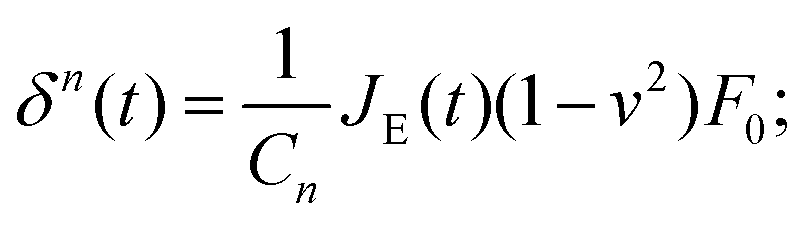 | (7) |
Again, the instantaneous approximation can introduce error into the analysis, and processing of the complete indentation history (the approach and hold phases) is preferable.55 Since the indentation depth increases throughout the experiment, the effects of nonlinearity and heterogeneity associated with the depth will be more pronounced; otherwise, data from these two types of experiments should agree with each other when performed on the same sample (Fig. 4).54
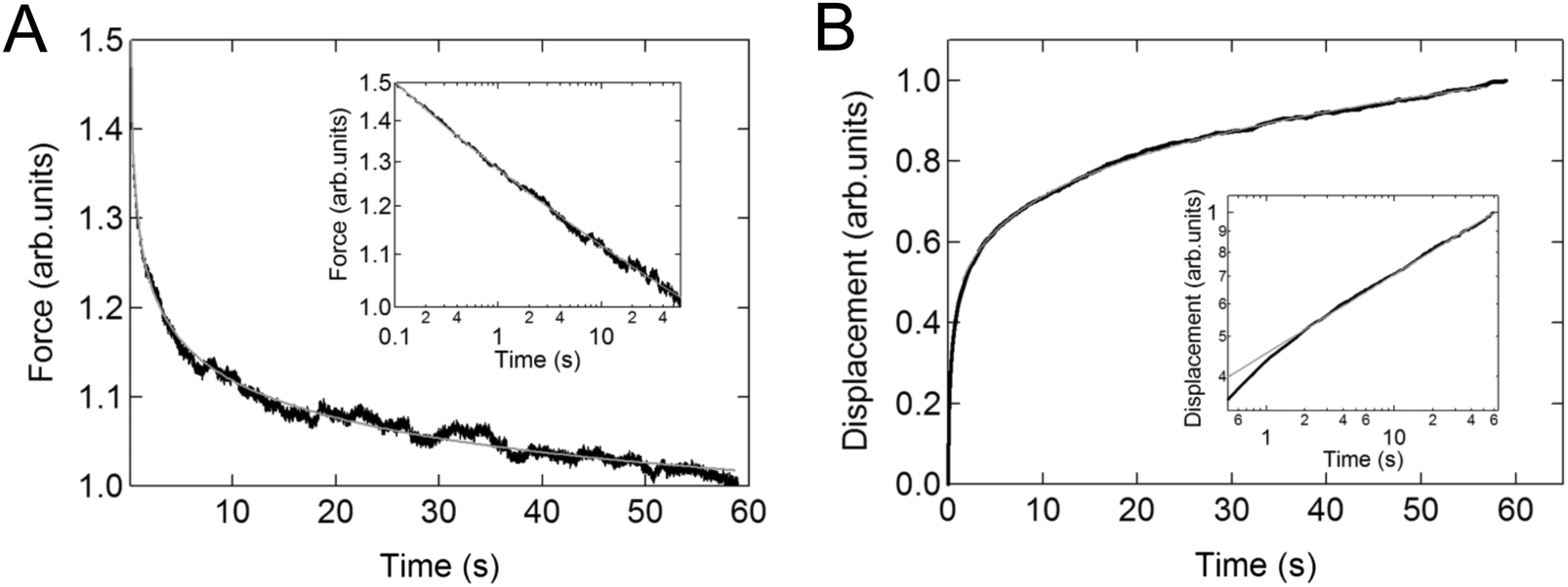 | ||
| Fig. 4 Example of relaxation and creep in the same cell. Linear plot of (A) the averaged stress relaxation and (B) the creep curve for NIH3T3 cells on a microarray. The insets show the corresponding relaxations on logarithmic axes. The solid lines represent the fit to the power-law function. Reproduced with permission from ref. 54, copyright 2009 The Japan Society of Applied Physics. | ||
As described in Section 2, the conventional force curves can also be used to extract the viscoelastic parameters of the sample, as the growth in the apparent Hertz's elastic modulus with an increase in indentation rate yields important viscoelastic information. The value of EHertz is indirectly proportional to the value of Young's relaxation function (more precisely, to its time-averaged value) at the indentation time. Hence, by conducting indentation measurements at several indentation rates/times, an idea of the relaxation function can be obtained. The dependency of the apparent elastic modulus on indentation rate has been used to obtain the power-law exponent7,50,51 or relaxation time66 of cells. Thus, when the Hertzian mechanics model is applied to the force curves, the piezo displacement speed should be mentioned in order to allow an adequate comparison between the data from different studies; instead, authors often give the acquisition frequency (in Hz), which can be quite misleading. Firstly, the piezo displacement generally takes the form of a triangle, rather than a sinusoidal movement. Secondly, and most importantly, the frequency is related to the complete piezo cycle, while contact takes place only during a certain part of this cycle. A more reasonable frequency can be obtained by accounting for the duration of only the contact part of the force cycle.47,67
3.2. Frequency domain experiments
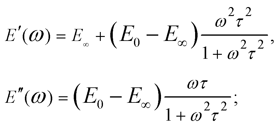
When the sample is subjected to oscillatory deformations with a controlled frequency ω and a constant (small) amplitude, the frequency-dependent Young's modulus can be obtained within the framework of linear viscoelasticity. In the AFM setup (also referred to as AFM microrheology, force/indentation modulation mode), the microcantilever is oscillated relative to the sample with a small fixed amplitude at several frequencies, either during the period of indentation2,59,68–73 or during the scanning process.74,75 The indentation can generally be described as a sine function of time, δ(t) = δ0 + δAsinωt, occurring around an operating indentation δ0, δA ≪ δ0. The force typically has both sine and cosine components: F(t) = F0 + F′sinωt + F′′cosωt. The elastic (storage) modulus of the material, E′(ω), is proportional to the in-phase (sine) component of the frequency-dependent indentation, and the viscous (loss) modulus, E′′(ω), is proportional to the out-of-phase (cosine) component. Together, these comprise the complex Young's modulus E*(ω) = E′(ω) + iE′′(ω) of the material, where  . If the material is an elastic solid, the force is exactly in phase with the input deformation and E′′(ω) = 0, while if the material is a viscous liquid, the induced stress is out of phase with the input deformation and E′′(ω) = 0. The loss tangent E′′(ω)/E′(ω) can therefore be used as an index of the solid-like or liquid-like behavior. For typical biological materials such as cells and tissues, the complex Young's modulus shows a pronounced dependency on the frequency of the strain. The frequency-dependent complex modulus and the relaxation Young's moduli in the time domain are related via the following transformation:61
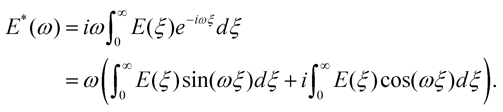 | (8) |
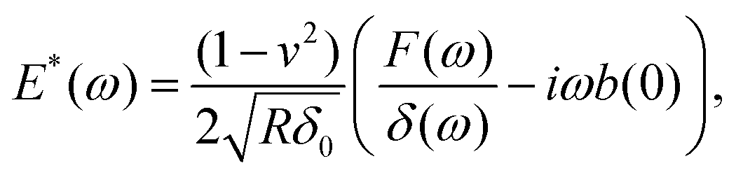
During the holding period, sinusoidal oscillations can be applied as discrete frequencies33,59,73,76 (Fig. 5). Alternatively, to reduce the time required for the experiment, multi-frequency signals can be applied that are composed of several sine waves68,77 or a sweep (chirp) signal in which frequency continuously increases with time.2,78,79 Oscillation can be applied to the Z-piezo or directly to the specially designed microcantilever using magnetic forces.75,80,81 When the applied frequencies are much lower than the microcantilever or the piezo resonance frequency, the analysis is simplified due to the nearly invariant amplitude and phase transfer function of the microcantilever. The analysis generally involves Fourier transforms of the force and indentation signals, F(ω) and δ(ω) respectively. For low-amplitude, off-resonance oscillations of the spherical indenter around an operating indentation δ0, an expression can be obtained for the complex Young's modulus33,59 as follows:
 | (9) |
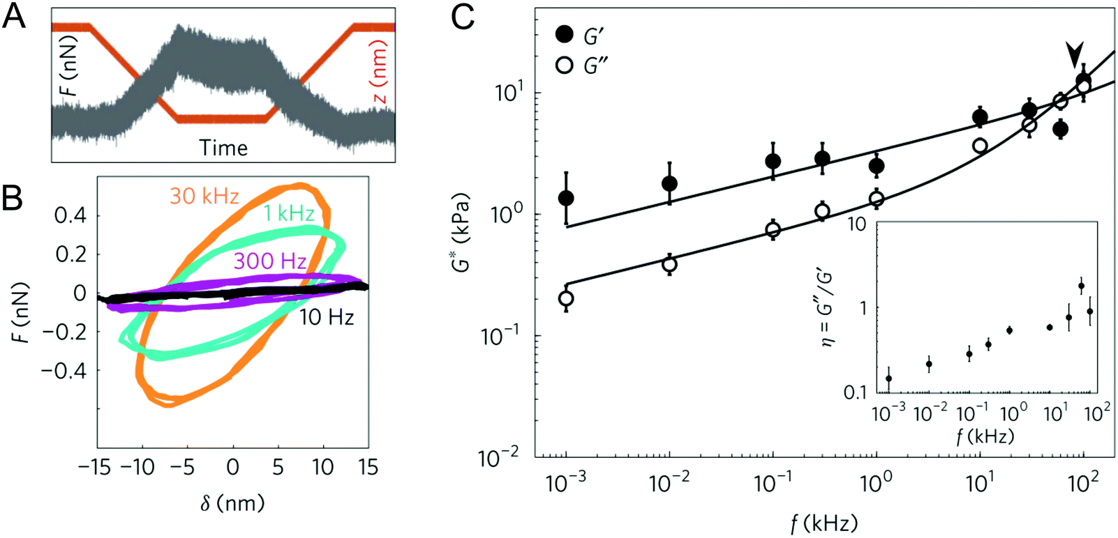 | ||
| Fig. 5 Experiments in the frequency domain: (A) example of the force–time trace at an oscillation of 1 kHz, obtained on a living cell; (B) force–indentation loops (also called Lissajous figures) obtained from the contact region of the force curves at different oscillation frequencies, showing increased slope and hysteresis with frequency; (C) frequency dependence of the complex shear modulus of 3T3 cells, fitted with a double power law (the arrowhead shows the transition frequency). Reproduced from ref. 76, with permission from Springer Nature, copyright 2017. | ||
When the microcantilever is directly excited at the resonance frequency, the signal is greatly enhanced. Moreover, a high frequency (usually in the kHz range in liquid) enables mechanical measurements to be made during fast scanning, since there is enough residence time at each pixel to obtain the amplitude and phase signal. A lock-in amplifier is generally used to obtain these quantities.74,75 The amplitude and phase changes are then analyzed using linear vibration theory (e.g. simple harmonic oscillator theory) and the viscoelastic parameters are extracted (Fig. 6J–L).82 Monitoring of the higher harmonic modes and bimodal excitation can be used to obtain data at even higher frequencies.74,83 The local stiffness, stiffness gradients and viscoelastic dissipation can be measured at a high spatial and temporal resolution; however, the physiological relevance of such high frequencies remains questionable.
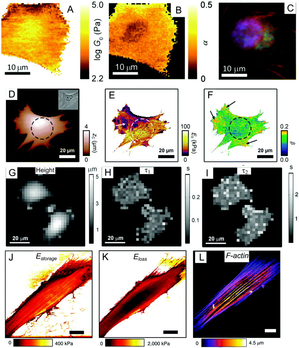 | ||
| Fig. 6 Mapping of the viscoelastic properties of a cell with AFM: (A–C) multi-frequency force modulation;68 (D–F) force clamp force mapping;55,89 (G–I) stress relaxation microscopy;90 (J–L) multi-harmonic dynamic AFM with directly excited microcantilevers.74,82 (A and B) show the power-law rheological parameters G0 (scaling parameter) and α mapped for a NIH 3T3 fibroblast (a description of these parameters is provided in Section 4.2); (C) immunofluorescence image of the nucleus (blue), actin filaments (red), and microtubules for the same cell region; (D) map of contact height and an optical phase contrast image (inset) for a mouse embryonic fibroblast (the nucleus position is marked by a dashed circle, cytoskeletal fibers are marked with arrows); (E and F) maps of the modulus scaling parameter E0 and the power-law exponent β for this cell; (G) height map at constant force (1 nN) for MCF7 cells; (H and I) corresponding maps for slow and fast relaxation times; (J and K) storage and loss moduli maps mapped over an NIH 3T3 fibroblast using direct excitation of the microcantilever at the resonance frequency (several kHz); (L) the actin cytoskeleton structure in the same living cell, with well-developed stress fibers (perinuclear actin cap). Panels A–C are adapted from ref. 68 with permission from AIP Publishing, copyright 2015. Panels D–F are adapted from ref. 55, CC-BY-3.0, published by The Royal Society of Chemistry. Panels G–I are adapted from ref. 90 with permission from Elsevier, copyright 2010. Panels J–L are adapted from ref. 82 with permission from Springer Nature, copyright 2018. | ||
The AFM-based characterization of biological samples is an actively developing area, and new experimental techniques for viscoelasticity measurements are often introduced. These include techniques based on an analysis of the thermal fluctuations of the AFM microcantilever above and in contact with the sample,84 estimation of viscoelastic parameters from the frequency dependence of the phase lag between the oscillating microsphere and the driving piezo at various heights above the sample,85 and contact resonance-based techniques.86 These are not commonly used, however.
3.3. AFM mapping of viscoelastic properties
Since the primary purpose of AFM is sub-micron imaging, a natural extension of the techniques mentioned above is the acquisition of images (maps) of the viscoelastic properties of the sample (mapping). The force volume technique is commonly used for elastic mapping, and involves point-by-point acquisition of the force curves over the sample area.87,88 By adding an oscillation (Fig. 6A–C)68,69 or a hold phase (Fig. 6D–I)55,89,90 into each force curve, the viscoelastic properties can be measured at each point. The shortcoming of this technique is its low acquisition speed (up to several hours); this is caused by the point-by-point movement of the microcantilever, which performs an approach-retract cycle at each point. A hold or oscillation phase can be added for viscoelastic analysis, or Ting's solution-based analysis can be applied to the standard force cycle. Recent improvements to instruments (fast force volume, PeakForce QNM) allow for much faster acquisition speeds (within minutes).67 It should be noted that a faster acquisition speed means that only high-frequency properties are measured, while low-frequency content is cut off from the analysis. Corrections to the hydrodynamic drag forces also become more important at higher acquisition speeds.67There have recently been several advances in viscoelastic property mapping techniques that utilize resonant microcantilevers oscillating at high frequencies, allowing the average amplitude (several nm), deflection, and phase to be obtained at each point as the microcantilever scans the surface (Fig. 6J–L).74,75,82 During a scan performed either in tapping or contact mode, the microcantilever indents the soft cell to depths of about 100 nm. Thus, the contact mechanics model can be applied to extract the complex Young's modulus with proper accounting for the microcantilever dynamics and hydrodynamic drag. Although this method is orders of magnitude faster than force-curve-based techniques for the same image resolution, again, only high-frequency data are obtained.
The spatial resolution of viscoelastic mapping is mainly determined by the tip–sample contact area,91 and thus may be adjusted by varying the tip shape and the applied force. Another parameter affecting the spatial resolution is the number of lines/points in the map (or the size of a pixel in nm). Since a larger number of points means a longer acquisition time, this value is selected as a compromise between the spatial and temporal resolution. The maps reveal large spatial variations in the viscoelastic parameters across the cell surface; the spatial dependence of the viscoelastic properties over the cell has been studied in several works, and no clear pattern in the properties of an on-center (over nucleus) versus off-center (over cell periphery) location have been found.55,68 In general, stiff subcellular components such as actin cytoskeleton fibers can be resolved on high-resolution maps.82 Advances based on a combination of AFM with optical techniques allow the matching of heterogeneities in local mechanical properties with fluorescent images of the different structures in living cells (Fig. 6C and L).
4. Viscoelastic constitutive models
The variety of experimental techniques reviewed in the previous section provide data that can be compared, systematized, and related to the viscoelastic properties of the sample, and a range of viscoelastic constitutive models has been created and used for these tasks. Constitutive modeling is a mathematical description that links the states of stress and strain with strain rates; however, it should be noted that a single viscoelastic model with a finite number of parameters cannot describe the behavior of any material over a full time/frequency range, due to the use of different relaxation mechanisms at different time/frequency scales. At very short time/high frequency scales, essentially no structural motions can occur during the measurement time, and the material behaves as an elastic or plastic solid, while at long timescales the material behavior is determined by passive natural decay processes. In living systems, on the other hand, cellular processes are active during the measurement time, and there is a constant turnover of cellular components. These time scales range from microseconds (molecular movements), minutes, and hours (cell migration) to days (multicellular rearrangements). Intermediate timescales (10−3 to 103 s) are of great interest, given their physiological relevance and relation to the object's mesoscale structure.Many different mathematical forms have been suggested and used for an analytical description of the viscoelastic behavior. Often, these models have an empirical origin that is based on ease of mathematical use, and a minimum number of parameters are required. To be physically meaningful, the relaxation functions E(t) should monotonically decrease with time (in the same way, the creep function should monotonically increase). Viscoelastic models with an analytic expression for E(t) can be divided into models with discrete or continuous relaxation spectra. Models based on a bottom-up approach, which are focused on the properties and interactions of individual molecular components, usually do not have analytical expressions on a whole-cell level, but are still able to provide valuable predictions of the sample behavior.
4.1. Spring-dashpot models
The simplest analytic viscoelastic constitutive models are obtained by combining spring and dashpot elements. The spring element represents ideal elastic behavior, in which the stress is proportional to the strain: σ(t) = kε(t), while the dashpot element represents the behavior of an ideal Newton liquid in which the stress is proportional to the strain rate: σ(t) = ηdε(t)/dt (where η is the viscosity). The two simplest combinations, i.e. a spring and dashpot in parallel and in series, are known as the Kelvin–Voigt and Maxwell elements. The former can be used to describe the stress relaxation behavior, and the latter the creep behavior, but not vice versa. The simplest combination with both behaviors is a spring in parallel with a Maxwell element, known as standard linear solid (SLS) model or a Zener model (Fig. 7A–C). The relaxation modulus and creep compliance for this model are, respectively:61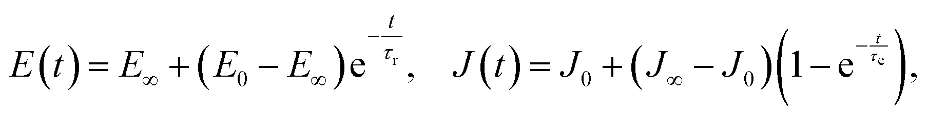 | (10) |
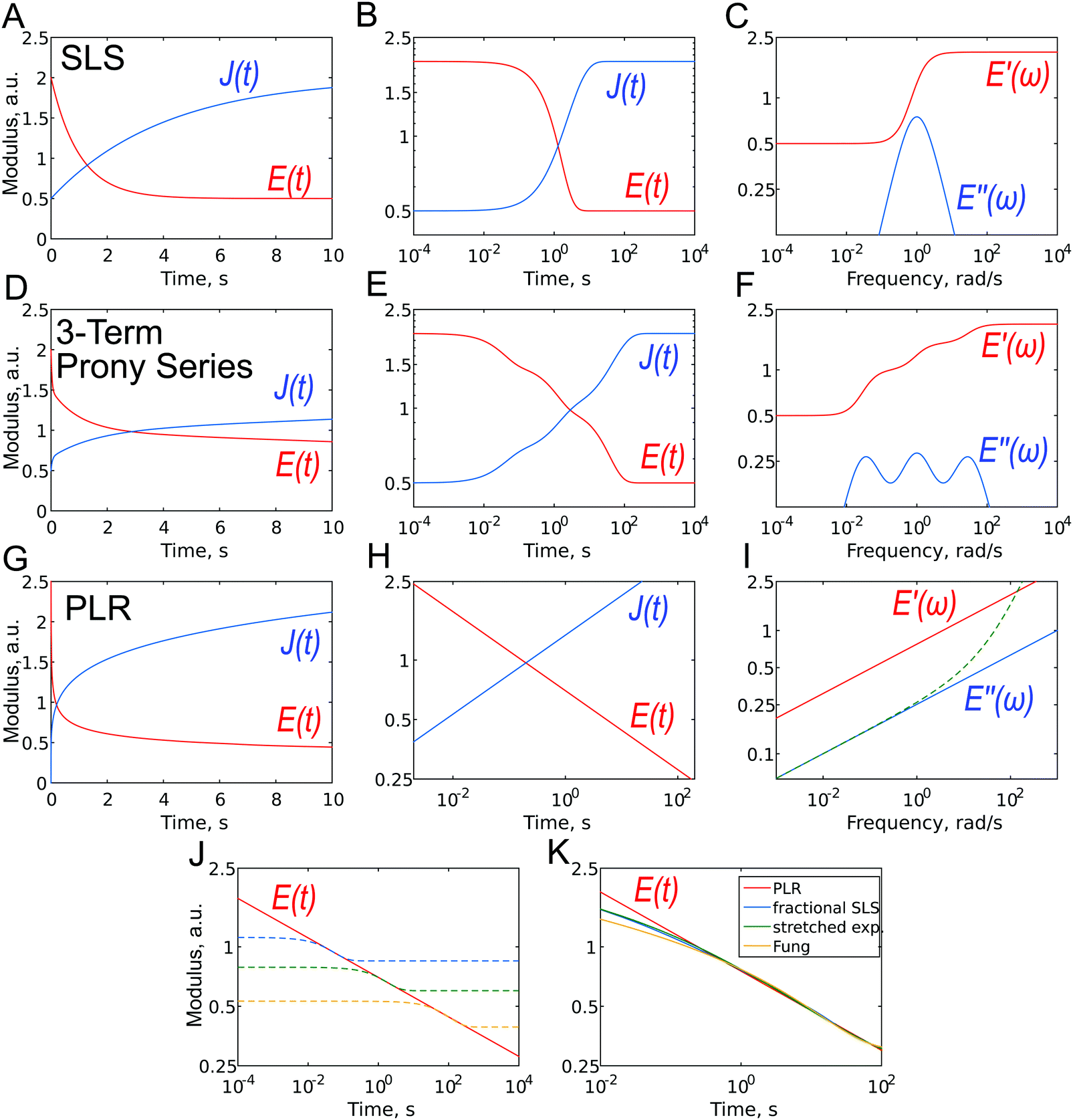 | ||
| Fig. 7 Different representations of viscoelastic constitutive models: (A–C) standard linear solid (SLS); (D–F) three-term Prony series: (G–I) power-law rheology (PLR) model. (A, D and G) E(t) and J(t), linear scale; (B, E, H) E(t) and J(t), log–log scale. The dashed line in (I) represents the loss modulus with the contribution from Newtonian viscosity. (J) PLR relaxation function (solid line) with three (dashed lines) SLS relaxation functions aligned to show the principal difference between the models. (K) Relaxation functions for several models with continuous relaxation spectra: PLR, fractional SLS, stretched exponent, and Fung's relaxation function. Except for shortest timescales, the functions are quite close to each other when parameters are adjusted. | ||
Due to the properties of the exponential function, most of the relaxation/creep occurs during one time decade (a factor of ten) (Fig. 7B and 2), and following this, the function returns rapidly to its long-term value. However, most biological materials relax or creep over many time decades, and this is better represented on a logarithmical scale. Although several authors have used the SLS model to obtain a characteristic relaxation time for the cell,56,92 this approach is contradictory since it can be shown that when the SLS model is applied to describe a continuous relaxation process, the result (relaxation time) depends on the duration of the experiment (Fig. 7J).24 The SLS model gives the following complex Young's modulus frequency behavior (Fig. 7C):
 | (11) |
The SLS model can be extended by the addition of more Maxwell elements (the so-called generalized Maxwell model), thus giving several relaxation times:
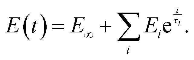 | (12) |
This function is often referred to as the Prony series (Fig. 7D–F). Models with two53,90 or three93 relaxation times have been used, where each relaxation time was presumably assigned to different cell structural elements (membrane + cortex, cytoplasm + cytoskeleton, nucleus). The addition of elements, however, leads to an increase in the number of fit parameters: there are a total of seven fitting parameters for a model with three Maxwell elements. This makes the fitting procedure less reliable, since the converged solutions may be non-unique due to the presence of local minima. In the words of John von Neumann: “With four parameters, I can fit an elephant, and with five I can make it wiggle its trunk”.94,95 In the frequency domain, broader Debye peaks are observed when elements have close relaxation times; several discrete Debye peaks are observed for distant relaxation times, and a “wavy” shape of the E′′(ω) curve is observed in the general case for moderately spaced relaxation times (Fig. 7F). The latter has not yet been confirmed in experiments on cells.
The number of Maxwell elements/relaxation times can be increased indefinitely, leading to a generalization of the expression for the Young's relaxation modulus:96
 | (13) |
 | (14) |
4.2. Viscoelastic models with continuous relaxation spectra
One way to obtain a relaxation model with a continuous relaxation spectrum is by introducing an element that depends on an α-order time derivative of the strain history σ(t) = Kαdαε(t)/dtα, where Kα is a fractional viscous coefficient with the units Pa s α.60,97,98 In this equation, for α = 0 we obtain the linear elastic one-dimensional constitutive equation, and for α = 1 we obtain a Newtonian dashpot (the symbol β is used instead of α in some works). For a value of α between zero and one, this fractional element (the so-called spring-pot element) can be realized physically through hierarchical arrangements of springs and dashpots such as ladders, trees or fractal structures. Importantly, for a single spring-pot element, the Young's relaxation function is a power law (Fig. 7G–I):| E(t) = Kα(t/τ)−α = E1t−α. | (15) |
In this case, it is normalized with a prefactor E1, which is the value of the Young's relaxation modulus at t = 1 s. The value of the power-law exponent measured with AFM for cells is within the range 0.05–0.4.2,31,59,89,99
The spring-pot element can be substituted into any other spring-dashpot model by replacing the spring, the dashpot element or both. For the spring-pot element in parallel, with a spring (E(t) = (E1 − E∞)t−α + E∞) or a dashpot (E(t) = E1t−α + ηδ(t)), the power-law behavior will be still preserved. The former is also known as a fractional-derivative Kelvin–Voigt (KVFD) model.100 Although the power-law rheology (PLR) model provides good results in terms of describing the relaxation behavior of cells,2,31,48,62,89,96 equations that are more complex than a simple power law will be obtained when another element is placed in series with it. For example, for the SLS model with a single spring-pot element instead of the dashpot element, the Young's relaxation function becomes (Fig. 7K):
 | (16) |
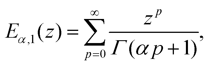
E α,1(z) is the Mittag–Leffler function, defined as:101
 | (17) |
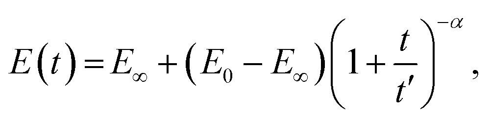
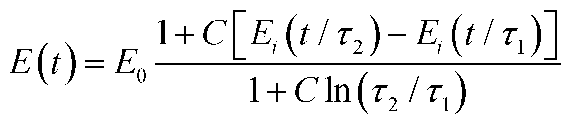
A pure power-law description (single spring-pot) of relaxation is not completely physically realistic, since it predicts an infinite modulus at time zero. A modified power-law function has therefore been suggested:98
 | (18) |
In several works on cells, a stretched exponential function known as the Kohlrausch–Williams–Watts (KWW) function103 has been employed for step-hold data analysis (Fig. 7K):
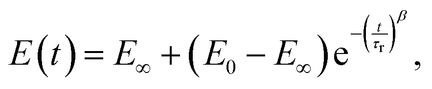 | (19) |
Another relaxation function with a continuous spectrum within a defined range was suggested by Neubert106 and has been successfully applied to biological samples by Fung24 (the expression without E0 is also known as Fung's reduced relaxation function) (Fig. 7K):
 | (20) |
Although all the relaxation functions presented here with a continuous spectrum are clearly different from the function with a single relaxation time (Fig. 7J), they are not very different from each other at the relevant time scales (Fig. 7K) and can therefore describe continuous relaxation almost equally well. It may be hard to select one of these models based on experimental data alone (which may also be noisy) so that a close fit can be obtained for all the models. Of these models, however, the simple power-law rheology model is most widely used in practice to describe cell properties. One of its advantages is that it has only two parameters with intuitive meaning: E1 provides an idea of the stiffness of the object, while the power-law exponent α reflects its closeness to a solid-like or liquid-like state. One surprising aspect, is that the power-law model was developed not only based on the fractional calculus, but also from a completely different background that is related to material molecular97 or mesoscopic composition.109 This is the soft glassy rheology (SGR) model developed by Sollich110,111 for soft disordered materials like foams, gels, and slurries. The theory assumes that the observed scale-free behavior is a natural consequence of the disorder and metastability of the internal structure of the material, which consists of many disordered elements that are held together by weak attractive forces and, as a result, are trapped in energy wells. Scale-free (power-law) rheology arises from a wide distribution of energy well depths and element lifetimes. The power-law exponent α is related to the effective temperature of the material (i.e. the amount of agitation energy in the system), which determines the probability of elements jumping between the energy wells and reflects the dynamics of the system. This jumping of elements between wells is the origin of the fluid-like behavior, and a higher effective temperature (power-law exponent) leads to more pronounced fluid-like features of the material. Thus, in the limit α = 0, soft glassy materials behave like elastic solids (elements are trapped in the walls) and in the limit α = 1 behave like viscous liquids (elements jump freely between the walls). The cytoskeleton of a cell may represent such a structure.28 SGR theory implies that changes in the level of internal disorder and the effective temperature associated with contraction or remodeling of the cytoskeleton can modulate the rheological behavior of the cell, and thus can provide a conceptual framework for processes such as cell migration, wound healing, invasion, metastasis and embryonic development.28
The power-law function has been successfully used to describe cell behavior in both the time54 and frequency domains.2,59,73,112 In the frequency domain, the equation for the complex Young's modulus is:
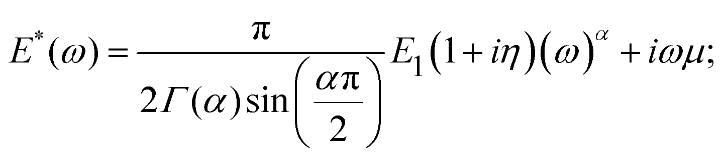 | (21) |
The loss tangent2 and power-law exponent31,71 are sensitive factors used to describe the cell condition. Moreover, the elastic modulus and the power-law exponent have been shown to be related to each other in cells: cells in the stiffest group displayed the lowest power-law exponent α, whereas cells in the softest group displayed the highest power-law exponent. After treatment of the cell with actin cytoskeleton-disturbing drugs, softening is accompanied by an increase in α. Based on the correlation between the elastic modulus and the power-law exponent, the existence of the master curve onto which all data can be collapsed has been postulated, originating from a fundamental relation between the prestress, stiffness and power-law exponent; however, the consistency and variability of these observations need to be investigated further. For further details, interested readers may refer to the related publications.25,28,113
At higher frequencies (above several hundred Hz), PLR with a higher exponent was observed (Fig. 5), and the viscoelastic behavior of cells was closely described by a sum of two power laws.76 Viscous dissipation of the thermally driven bending fluctuations of the cytoskeletal filaments with different levels of tension is thought to dominate the system's frictional response at high frequencies.114
4.3. Other models
An alternative approach to describe hydrogels is based on poroelasticity theory, which attributes the time-dependence of the mechanical properties to the flow of a fluid through a porous solid network. The characteristic relaxation time constant predicted by poroelasticity theory (τporo = a2/D) depends on both the characteristic contact length scale (e.g., contact radius) and the effective diffusivity D of the solvent through the network, which in turn depends on the properties of the solvent and the solid phase (viscosity, pore size, etc.). An approximate solution was obtained by finite-element simulations for force-relaxation experiments:115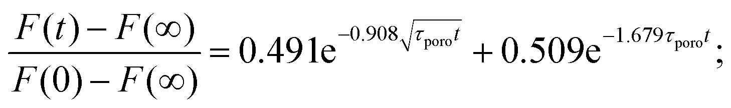 | (22) |
A wide range of models based on a bottom-up approach can be used to provide predictions about time-dependent material behavior. Most of these models utilize the fact that fibrous networks promote mechanical strength and support integrity, at the level of both the cell and the tissue. The properties of these networks arise from the organization and behavior of their constituent filaments and crosslinks. Comprehensive models have been developed for individual semiflexible filaments, such as a worm-like chain (WLC) model and more complicated models (glassy WLC, inelastic glassy WLC, prestressed semiflexible chain, and others, as reviewed in ref. 28 and 119). These models have been found to be useful in describing reconstructed actin gels with a controlled number of components. However, quantitative prediction of the mechanical parameters of the cell is difficult due to the high levels of heterogeneity and variability in the structural parameters of the cytoskeleton (mesh size, filament length, cross-link strength).
Given the wide range of available viscoelastic models, it can be difficult to select the most appropriate one for a specific sample. Moreover, the use of different models for the same types of samples (e.g., cells) can make a comparison of data from different studies more complicated. For example, Fig. 6 shows the viscoelastic parameters obtained for cells using three different models: power-law rheology (Fig. 6A–F), the generalized Maxwell model (Fig. 6G–I), and the Kelvin–Voight model (Fig. 6J–L). Standardization of the measured viscoelastic parameters will help to enable data comparison in the future.
It should be noted that most of the viscoelastic models can describe viscoelastic behavior equally well within a narrow range.31,107 Thus, the applicability of a model to a specific sample should be confirmed by conducting experiments over a wide range of times/frequencies (Fig. 2). However, when the applicability of a particular model is confirmed, the acquisition of further data can be limited to a narrow range for higher throughput analysis. Information about these models is summarized in Table 2.
| Model | Description | |
|---|---|---|
| Spring-dashpot models | Kelvin–Voight and Maxwell models49 | The two simplest viscoelastic models. The Maxwell model can describe the stress relaxation behavior, and the Kelvin–Voight model can describe the creep behavior. These have limited applicability to real materials |
| + Simplicity | ||
| Standard linear solid (SLS) model56,92 | Describes exponential relaxation, and can be described with three parameters: instantaneous modulus, long-term modulus, and relaxation time. The material manifests viscoelastic behavior only at times/frequencies which are close to this relaxation time | |
| + Simplicity | ||
| − Most of the biological samples show viscoelastic behavior over a wide range of times/frequencies | ||
| Generalized Maxwell model53,90,93 | A model with several relaxation times | |
| + Can potentially describe any experimental data | ||
| − Uses a large number of fit parameters, which decreases the reliability of the fit | ||
| Models with continuous relaxation spectrum | Power-law rheology and related models (also soft glassy rheology)2,31,48,62,89,96 | A factional element (spring-pot) element (single or in parallel combination with a spring or dashpot) provides the power-law relaxation. The main parameters are the power-law exponent and the modulus scaling parameter (e.g., modulus at t = 1 s) |
| + Simplicity | ||
| + Can closely describe the experimental data obtained for cells | ||
| More complex fractional models102 | A factional element in different combinations with spring/dashpot elements and other fractional elements | |
| + Can describe different types of viscoelastic behavior and transitions from one type to another with a relatively small number of fit parameters | ||
| − Complex | ||
| Stretched exponential function104,105 | The exponent is empirically employed in the SLS model to represent the dispersion processes of the relaxation times in the system | |
| + Relatively simple | ||
| − Empirical | ||
| Fung's reduced relaxation function57,107 | Continuous relaxation spectrum in the interval between two relaxation times | |
| + Can closely describe the experimental data obtained on tissues | ||
| − The parameters of the function show low sensitivity | ||
| Other models | Poroelasticity116–118 | The model attributes the time-dependence of mechanical properties to the flow of a fluid through a porous solid network. The main parameter (characteristic relaxation time constant) depends on the characteristic contact length scale (e.g., the contact radius) and the effective diffusivity of the solvent through the pores of the solid phase |
| + Can closely describe experimental data obtained on hydrogels | ||
| − In biological samples, poroelasticity and viscoelasticity coexist | ||
| Worm-like chain (WLC) and related models28 | Describes the viscoelastic behavior of systems consisting of semiflexible filaments | |
| + Can closely describe experimental data obtained on the reconstructed actin gels | ||
| − Has difficulty with quantitative predictions for complex biological samples such as cells |
5. Challenges and limitations
Numerous factors create uncertainties in mechanical measurements made using AFM, and these can lead to large variations in the results acquired with different instruments, laboratories, and operators. These factors include the tip geometry, determination of the spring constant and the deflection sensitivity. Studies devoted to the analysis and minimization of uncertainties have resulted in the development of standardized procedures for data acquisition and analysis, leading to a significant improvement in the consistency and reproducibility of the elastic modulus extracted using AFM.120–122 For viscoelastic analysis, no such standardization or uncertainty quantification currently exists, although general agreement between different techniques has been shown in several studies.31,54,62Although continuous attempts are being made to link the observed viscoelastic parameters with specific biological structures, the overall task still remains challenging. Biological samples have a very complex structure with a large number of constituents. In the case of cells, the most important structure that determines the viscoelastic behavior is the actin cytoskeleton. This is evidenced by a comparison of data obtained on cells and reconstructed actin gels,28 as well as by studying cells with naturally (e.g., cancer cells58,89,123) or experimentally (e.g., treated with inhibitors49,53,107) modified cytoskeletons. The SGR model described above currently provides one of the best predictions relating the observed state of the cytoskeleton to the viscoelastic properties of different cell types and experimental treatments.28 However, the roles of other cellular components (e.g., the nucleus, microtubules and intermediate filaments) and overall cellular heterogeneity still need to be established, and this will require deeper knowledge of the internal cell structure and combined use of cell imaging, mechanical measurements and modeling.
The actin cytoskeleton is distributed non-homogenously throughout the cell; it is concentrated in the layer under the plasma membrane (cortex) and forms stress fibers in some types of cells. These stress fibers can often be seen on viscoelastic maps as more solid-like structures.55,67 The presence of an actin cortex leads to inhomogeneity of the cell properties over its depth. This may be another source of the depth-dependency of the measured modulus, and also a possible reason for the effect of tip size on the measured properties. As has been shown in several studies,48,67,124 the measured stiffness (e.g., the effective elastic modulus or the scaling factor of the PLR model) is higher when sharp tips are used, and lower when larger microspheres are used. Simulations have shown that the sharp tip is mostly probing a response from the stiff cortex in the surface layer, while strains arising from the large spherical probe are distributed more evenly throughout the deeper, softer layers (cytoplasm).124
In AFM experiments, linear viscoelastic behavior of the sample is commonly assumed, and this is justified by the usage of low indentation depths. This can be experimentally confirmed by varying the indentation depths, as the extracted viscoelastic parameters should not depend on the indentation depth within reasonable limits.69 In oscillatory experiments, the Lissajous figures should be symmetric and elliptical (Fig. 5), although nonlinearity may be shown at large deformations. One approach that can be used to treat this is quasi-linear viscoelasticity (QLV) theory, which was developed by Fung.24 The main hypothesis of this theory is that the relaxation function can be separated into a time-dependent part, i.e. the reduced relaxation function φ(t), and a strain (indentation depth)-dependent part, i.e. an instantaneous non-linear elastic responseT(e)(δ):24
| K(δ,t) = T(e)(δ)φ(t). | (23) |
As mentioned earlier, a reduced relaxation function can be obtained by normalizing the relaxation functions; this is a unitless function with value one at t = 0. The nonlinear elastic response can have different forms, for example the Mooney-Rivlin, Neo-Hookean, Ogden, and Fung functions.125–127 Different combinations of elastic response functions and the reduced relaxation function can be tested, and this is an interesting subject for future work. A simpler related example is a nonlinearity that arises not from the material properties but from geometric nonlinearities, due to large deformations in the presence of an underlying stiff substrate effect. Due to this effect, the thin material at large indentation depth (>10–20% of the thickness) seems stiffer than expected. It has been shown using finite element modeling that this effect depends on the indentation depth but not the time.128 Thus, the correction factor can be applied as a function of indentation depth only, allowing an analysis of the thin parts of cells and thin gels.129
In some cases, the applied force causes irreversible deformation (plasticity) in the cell structure. In particular, incomplete cell recovery was observed after repeated indentation (10 times) of the cells with high force (10 nN).52 It is believed that this irreversible deformation originates from bond ruptures within the cytoskeleton.130 Complete recovery of the cell's shape was observed at smaller forces (1–2 nN).105,131 The application of force, especially prolonged, can lead to an active response from the cell, and may for example cause an increase in indentation depth instead of the expected decrease during the creep experiments.132 Mechanosensing responses may also be activated in the cell due to the action of the microcantilever,133 but even without this activation, active cell behavior (such as moving) can affect the experiment.
Adhesion may play a significant role at the scale of AFM experiments due to the effects of interfacial energies. In indentation experiments, adhesion is usually revealed as the additional tensile force required to separate the surfaces, and adhesion hysteresis is frequently observed, i.e., more work is required to separate the surfaces than is gained when creating the contact. Adhesion therefore creates an additional source of hysteresis, and separating the contributions from adhesion and viscoelasticity can be a nontrivial task.134–137 In oscillatory experiments, adhesion forces can keep the contact area constant, since the load is cycled at small amplitudes. The model therefore needs to be modified, and the dynamic punch model (constant contact area during cycling) has been found to capture the observed viscoelastic behavior more accurately.80 Stress relaxation and creep experiments should be less affected by the adhesion since neither of them involve surface separation. The JKR (Johnson–Kendall–Roberts) model is generally applicable to soft samples in a liquid environment.138 More complicated models are required in which the bulk and interfacial viscoelasticities are distinguished, and the adhesion itself is dependent on the indentation time and rate.131 It is possible, however, to reduce the adhesive force between the probe and the cell surface by proper cleaning and hydrophobic modification of the probe54 or by the addition of interaction-screening molecules in the medium. Using criteria suggested by Johnson,139 adhesion can be safely ignored when the ratio of the maximum adhesive force to the maximum loading force is below 5%.
6. The AFM technique and other methods of viscoelastic characterization
AFM is an active microrheology method, in which force and deformation are applied to the cell to take measurements.140 Other active methods include magnetic twisting cytometry (MTC),141 optical traps,7 microplate manipulation142 and micropipette aspiration.143 While the latter two of these are usually used to probe mechanics at the whole cell level, the other techniques mentioned here are designed to allow for analysis at the subcellular level. AFM can be used both at the level of the whole cell (with tipless microcantilevers or large spheres attached) and for the high-resolution mapping of mechanical properties. Compared to other methods, AFM also has one of the largest available ranges of forces and frequencies. The basic principles of viscoelastic characterization using AFM are close to those of techniques using micro- and nanoindenters.144,145 Thus, many concepts associated with viscoelastic analysis could be shared between these techniques, especially in relation to data processing.In passive methods, the ability of a cell to generate forces and deform its environment is monitored, typically by tracking the movement of marker particles, which may be part of the cell or the substrate (including laser tracking microrheology (LTM),146 traction force microscopy (TFM)9) In principle, AFM can be combined with most passive techniques to obtain a more complete picture of the cell biomechanics. For example, a combination of AFM and TFM has allowed a correlation to be revealed between the viscoelastic properties and contractile prestress of living cells.147
It should be remembered that AFM is an external technique, meaning that it probes the surface of the sample. In this sense, AFM results are usually different from those of methods measuring the intracellular rheology, such as LTM, but are in typically in agreement with those of methods measuring surface response, such as MTC.146 While the surface response is mostly governed by the actin cytoskeleton, including the cortex and stress fibers, the intracellular response is dependent on the rheological properties of the deeper cytoplasm.
7. Perspectives
While significant progress has been made in recent years in the understanding of cell mechanics, many fundamental questions remain unanswered, for example, are the assumptions underlying the mechanical models used here actually valid? How do the anisotropy and inhomogeneity of the cell structure affect the indentation and the physiological behavior of the cell? How do the cytoskeleton and other cell components interact to produce the observed viscoelastic behavior? Being able to fully answer these questions requires a systematic approach in order to correlate the cell structure with local physical properties. There is a clear trend towards combining AFM with other methods such as confocal microscopy, where the results obtained for the same object can complement each other effectively.39,148 A combination with finite element modeling is one of the promising approaches to data analysis.149,150Mining and extracting knowledge of the physical properties of a cell from these multi-dimensional data requires a deep understanding of the physics of the cell and the measurement process. At the same time, the simplest models, such as Hertz's contact model, are still mostly used by the AFM community for interpretation of the experimental data, due to the complicated data processing steps in viscoelastic analysis. This issue may be resolved by the dissemination of computational tools and the implementation of established experimental protocols in AFM software.
A more complete data analysis will help in the understanding of physiological and pathological processes such as differentiation, transformation, and regeneration, and potentially in the development of new diagnostic techniques, biomedical devices, and consumer products.
8. Conclusions
AFM techniques are versatile, and allow for a wide range of time/frequencies, forces, and spatial resolutions, making them very suitable for the viscoelastic characterization of biological samples, especially at the single-cell level. While a large amount of data on the viscoelastic properties of cells has been collected, the choice of an appropriate viscoelastic model for a particular sample continues to be a topic of debate. This is related to the complex nature of the cell, including effects arising from heterogeneity, anisotropy, and active cell responses. A combination of AFM with optical imaging techniques and passive rheological methods can provide a valuable tool for the development and testing of cell viscoelastic models that can be further used in diagnosis, treatment, and regenerative medicine.Conflicts of interest
There are no conflicts of interest to declare.Acknowledgements
We apologize to all authors whose work we were unable to cite due to space constraints. This work was financed in part by the National Science Foundation through the CMMI GOALI grant 1726274. Support for Y. E. via the Russian academic excellence project “5-100” (Section 3), and the Russian Science Foundation under grant 19-79-00354 (Section 4) is gratefully acknowledged.References
- M. Lekka, K. Pogoda, J. Gostek, O. Klymenko, S. Prauzner-Bechcicki, J. Wiltowska-Zuber, J. Jaczewska, J. Lekki and Z. Stachura, Micron, 2012, 43, 1259–1266 CrossRef PubMed.
- J. Rother, H. Nöding, I. Mey and A. Janshoff, Open Biol., 2014, 4, 140046 CrossRef PubMed.
- R. W. van Zwieten, S. Puttini, M. Lekka, G. Witz, E. Gicquel-Zouida, I. Richard, J. A. Lobrinus, F. Chevalley, H. Brune, G. Dietler, A. Kulik, T. Kuntzer and N. Mermod, Nanomedicine, 2014, 9, 393–406 CrossRef CAS.
- E. M. Darling, M. Topel, S. Zauscher, T. P. Vail and F. Guilak, J. Biomech., 2008, 41, 454–464 CrossRef.
- R. M. Hochmuth, J. Biomech., 2000, 33, 15–22 CrossRef CAS.
- N. H. Reynolds, W. Ronan, E. P. Dowling, P. Owens, R. M. McMeeking and J. P. McGarry, Biomaterials, 2014, 35, 4015–4025 CrossRef CAS PubMed.
- S. Nawaz, P. Sánchez, K. Bodensiek, S. Li, M. Simons and I. A. T. Schaap, PLoS One, 2012, 7, e45297 CrossRef CAS PubMed.
- B. Fabry, G. Maksym, J. Butler, M. Glogauer, D. Navajas and J. Fredberg, Phys. Rev. Lett., 2001, 87, 1–4 CrossRef.
- U. S. Schwarz and J. R. D. Soiné, Biochim. Biophys. Acta, Mol. Cell Res., 2015, 1853, 3095–3104 CrossRef CAS.
- C. M. Kraning-Rush, S. P. Carey, J. P. Califano and C. A. Reinhart-King, Methods Cell Biol., 2012, 110, 139–178 Search PubMed.
- S. V. Plotnikov, B. Sabass, U. S. Schwarz and C. M. Waterman, High-Resolution Traction Force Microscopy, Elsevier Inc., 1st edn, 2014, vol. 123 Search PubMed.
- J. M. Mattice, A. G. Lau, M. L. Oyen and R. W. Kent, J. Mater. Res., 2006, 21, 2003–2010 CrossRef CAS.
- T. Okajima, in Nano/Micro Science and Technology in Biorheology, ed. R. Kita and T. Dobashi, Springer, Japan, Tokyo, 2015, pp. 387–414 Search PubMed.
- M. Chyasnavichyus, S. L. Young and V. V. Tsukruk, Jpn. J. Appl. Phys., 2015, 54, 08LA02 CrossRef.
- R. Benitez and J. L. Toca-herrera, Microsc. Res. Tech., 2014, 958, 947–958 CrossRef.
- J. Chen, Interface Focus, 2014, 4, 20130055 CrossRef PubMed.
- C. A. Putman, K. O. van der Werf, B. G. de Grooth, N. F. van Hulst and J. Greve, Biophys. J., 1994, 67, 1749–1753 CrossRef CAS.
- S. G. Shroff, D. R. Saner and R. Lal, Am. J. Physiol., 1995, 269, C286–C292 CrossRef CAS.
- N. O. Petersen, W. B. McConnaughey and E. L. Elson, Proc. Natl. Acad. Sci. U. S. A., 1982, 79, 5327–5331 CrossRef CAS.
- F. H. C. Crick and A. F. W. Hughes, Exp. Cell Res., 1950, 1, 37–80 CrossRef.
- C. Rianna and M. Radmacher, Eur. Biophys. J., 2017, 46, 309–324 CrossRef CAS.
- A. R. Cameron, J. E. Frith and J. J. Cooper-White, Biomaterials, 2011, 32, 5979–5993 CrossRef CAS.
- J. Toyjanova, E. Hannen, E. Bar-Kochba, E. M. Darling, D. L. Henann and C. Franck, Soft Matter, 2014, 10, 8095–8106 RSC.
- Y.-C. Fung, Biomechanics, Springer New York, New York, NY, 1993, pp. 242–320 Search PubMed.
- B. D. Hoffman and J. C. Crocker, Annu. Rev. Biomed. Eng., 2009, 11, 259–288 CrossRef CAS.
- C. Verdier, J. Theor. Med., 2003, 5, 67–91 CrossRef.
- C. Verdier, J. Etienne, A. Duperray and L. Preziosi, C. R. Phys., 2009, 10, 790–811 CrossRef CAS.
- P. Kollmannsberger and B. Fabry, Annu. Rev. Mater. Res., 2011, 41, 75–97 CrossRef CAS.
- N. Özkaya, M. Nordin, D. Goldsheyder and D. Leger, Fundamentals of Biomechanics, Springer New York, New York, NY, 2012, vol. 86, pp. 221–236 Search PubMed.
- R. H. Pritchard, Y. Y. S. Huang and E. M. Terentjev, Soft Matter, 2014, 10, 1864–1884 RSC.
- Y. M. Efremov, W.-H. Wang, S. D. Hardy, R. L. Geahlen and A. Raman, Sci. Rep., 2017, 7, 1541 CrossRef.
- L. Puricelli, M. Galluzzi, C. Schulte and A. Podest, Rev. Sci. Instrum., 2015, 86, 033705 CrossRef PubMed.
- R. E. Mahaffy, C. K. Shih, F. C. MacKintosh and J. Käs, Phys. Rev. Lett., 2000, 85, 880–883 CrossRef CAS.
- R. E. Mahaffy, S. Park, E. Gerde, J. Käs and C. K. Shih, Biophys. J., 2004, 86, 1777–1793 CrossRef CAS.
- H. Hertz, Journal für die Reine und Angewandte Mathematik, 1881, 92, 156–171 Search PubMed.
- I. N. Sneddon, Int. J. Eng. Sci., 1965, 3, 47–57 CrossRef.
- F. Rico, P. Roca-Cusachs, N. Gavara, R. Farré, M. Rotger and D. Navajas, Phys. Rev. E: Stat., Nonlinear, Soft Matter Phys., 2005, 72, 21914 CrossRef PubMed.
- B. Wang, P. Lancon, C. Bienvenu, P. Vierling, C. Di Giorgio and G. Bossis, Micron, 2013, 44, 287 CrossRef.
- A. R. Harris and G. T. Charras, Nanotechnology, 2011, 22, 345102 CrossRef.
- G. G. Bilodeau, J. Appl. Mech., 1992, 59, 519–523 CrossRef.
- A. M. Collinsworth, S. Zhang, W. E. Kraus and G. A. Truskey, Am. J. Physiol., 2002, 283, C1219–C1227 CrossRef CAS.
- A. B. Mathur, A. M. Collinsworth, W. M. Reichert, W. E. Kraus and G. A. Truskey, J. Biomech., 2001, 34, 1545–1553 CrossRef CAS.
- L. M. Rebelo, J. S. de Sousa, J. Mendes Filho and M. Radmacher, Nanotechnology, 2013, 24, 055102 CrossRef CAS.
- T. C. T. Ting, J. Appl. Mech., 1966, 33, 845–854 CrossRef.
- G. A. C. Graham, Int. J. Eng. Sci., 1967, 5, 495–514 CrossRef.
- E. H. Lee and J. R. M. Radok, J. Appl. Mech., 1960, 27, 438–444 CrossRef.
- J. S. de Sousa, J. A. C. Santos, E. B. Barros, L. M. R. Alencar, W. T. Cruz, M. V. Ramos and J. M. Filho, J. Appl. Phys., 2017, 121, 034901 CrossRef.
- B. R. Brückner, H. Nöding and A. Janshoff, Biophys. J., 2017, 112, 724–735 CrossRef.
- P. D. Garcia, C. R. Guerrero and R. Garcia, Nanoscale, 2017, 9, 12051–12059 RSC.
- Y. M. Efremov, A. A. Dokrunova, D. V. Bagrov, K. S. Kudryashova, O. S. Sokolova and K. V. Shaitan, J. Biomech., 2013, 46, 1081–1087 CrossRef.
- J. Ren, S. Yu, N. Gao and Q. Zou, Phys. Rev. E: Stat., Nonlinear, Soft Matter Phys., 2013, 88, 052711 CrossRef.
- H. W. Wu, T. Kuhn and V. T. Moy, Scanning, 1998, 20, 389–397 CrossRef CAS.
- S. Moreno-Flores, R. Benitez, M. D. M. Vivanco and J. L. Toca-Herrera, Nanotechnology, 2010, 21, 445101 CrossRef.
- S. Hiratsuka, Y. Mizutani, A. Toda, N. Fukushima, K. Kawahara, H. Tokumoto and T. Okajima, Jpn. J. Appl. Phys., 2009, 48, 08JB17 CrossRef.
- F. M. Hecht, J. Rheinlaender, N. Schierbaum, W. H. Goldmann, B. Fabry and T. E. Schäffer, Soft Matter, 2015, 11, 4584–4591 RSC.
- E. Darling, S. Zauscher and F. Guilak, Osteoarthritis Cartilage, 2006, 14, 571–579 CrossRef CAS.
- S. Tripathy and E. J. Berger, J. Biomech. Eng., 2009, 131, 094507 CrossRef CAS.
- A. N. Ketene, E. M. Schmelz, P. C. Roberts and M. Agah, Nanomedicine, 2012, 8, 93–102 CrossRef CAS.
- J. Alcaraz, L. Buscemi, M. Grabulosa, X. Trepat, B. Fabry, R. Farré and D. Navajas, Biophys. J., 2003, 84, 2071–2079 CrossRef CAS.
- R. L. Magin, CRC Crit. Rev. Bioeng., 2004, 32, 105–194 Search PubMed.
- R. Lakes, Viscoelastic Materials, Cambridge University Press, Cambridge, 2009 Search PubMed.
- R. Takahashi and T. Okajima, Jpn. J. Appl. Phys., 2016, 55, 08NB22 CrossRef.
- M. Li, L. Liu, X. Xu, X. Xing, D. Dang, N. Xi and Y. Wang, J. Mech. Behav. Biomed. Mater., 2018, 82, 193–201 CrossRef.
- T. C. Doehring, E. O. Carew and I. Vesely, Ann. Biomed. Eng., 2004, 32, 223–232 CrossRef.
- H. Zhang, Y. Wang, M. Fatemi and M. F. Insana, Meas. Sci. Technol., 2017, 28, 035703 CrossRef.
- M. A. Caporizzo, C. M. Roco, M. C. C. Ferrer, M. E. Grady, E. Parrish, D. M. Eckmann and R. J. Composto, NanoBioMedicine, 2015, vol. 2, p. 9 Search PubMed.
- Y. M. Efremov, A. I. Shpichka, S. L. Kotova and P. S. Timashev, Soft Matter, 2019, 15, 5455–5463 RSC.
- R. Takahashi and T. Okajima, Appl. Phys. Lett., 2015, 107, 173702 CrossRef.
- M. Dokukin and I. Sokolov, Sci. Rep., 2015, 5, 12630 CrossRef CAS.
- D. Schneider, T. Baronsky, A. Pietuch, J. Rother, M. Oelkers, D. Fichtner, D. Wedlich and A. Janshoff, PLoS One, 2013, 8, e80068 CrossRef.
- Y. M. Efremov, A. A. Dokrunova, A. V. Efremenko, M. P. Kirpichnikov, K. V. Shaitan and O. S. Sokolova, Biochim. Biophys. Acta, Mol. Cell Res., 2015, 1853, 3117–3125 CrossRef CAS PubMed.
- L. M. Rebelo, J. S. De Sousa, T. M. Santiago and J. M. Filho, in Microscopy: advances in scientific research and education, ed. A. Méndez-Vilas, Formatex Research Center, 2014, pp. 141–152 Search PubMed.
- B. A. Smith, B. Tolloczko, J. G. Martin and P. Grütter, Biophys. J., 2005, 88, 2994–3007 CrossRef CAS.
- A. X. Cartagena-Rivera, W.-H. Wang, R. L. Geahlen and A. Raman, Sci. Rep., 2015, 5, 11692 CrossRef CAS.
- A. Raman, S. Trigueros, A. Cartagena, A. P. Z. Stevenson, M. Susilo, E. Nauman and S. A. Contera, Nat. Nanotechnol., 2011, 6, 809–814 CrossRef CAS.
- A. Rigato, A. Miyagi, S. Scheuring and F. Rico, Nat. Phys., 2017, 13, 771–775 Search PubMed.
- P. Roca-Cusachs, I. Almendros, R. Sunyer, N. Gavara, R. Farré and D. Navajas, Biophys. J., 2006, 91, 3508–3518 CrossRef CAS.
- A. U. Kareem and S. D. Solares, Nanotechnology, 2011, 23, 015706 CrossRef.
- M. Schächtele, E. Hänel and T. E. Schäffer, Appl. Phys. Lett., 2018, 113, 093701 CrossRef.
- P. C. Nalam, N. N. Gosvami, M. A. Caporizzo, R. J. Composto and R. W. Carpick, Soft Matter, 2015, 11, 8165–8178 RSC.
- L. M. Rebêlo, J. S. de Sousa, J. Mendes Filho, J. Schäpe, H. Doschke and M. Radmacher, Soft Matter, 2014, 10, 2141–2149 RSC.
- Y. M. Efremov, A. X. Cartagena-Rivera, A. I. M. Athamneh, D. M. Suter and A. Raman, Nat. Protoc., 2018, 13, 2200–2216 CrossRef CAS.
- R. Garcia and R. Proksch, Eur. Polym. J., 2013, 49, 1897–1906 CrossRef CAS.
- F. Benmouna and D. Johannsmann, Langmuir, 2004, 20, 188–193 CrossRef CAS.
- N. Gavara and R. S. Chadwick, Nat. Methods, 2010, 7, 650–654 CrossRef CAS.
- A. B. Churnside, R. C. Tung and J. P. Killgore, Langmuir, 2015, 31, 11143–11149 CrossRef CAS.
- C. Rotsch and M. Radmacher, Biophys. J., 2000, 78, 520–535 CrossRef CAS.
- E. A-Hassan, W. F. Heinz, M. D. Antonik, N. P. D’Costa, S. Nageswaran, C. A. Schoenenberger and J. H. Hoh, Biophys. J., 1998, 74, 1564–1578 CrossRef CAS.
- N. Schierbaum, J. Rheinlaender and T. E. Schäffer, Acta Biomater., 2017, 55, 239–248 CrossRef CAS.
- S. Moreno-Flores, R. Benitez, M. D. Vivanco and J. L. Toca-Herrera, J. Biomech., 2010, 43, 349–354 CrossRef.
- F. Braet, C. Rotsch, E. Wisse and M. Radmacher, Appl. Phys. A: Mater. Sci. Process., 1998, 66, 575–578 CrossRef.
- A. Yango, J. Schäpe, C. Rianna, H. Doschke and M. Radmacher, Soft Matter, 2016, 12, 8297–8306 RSC.
- H. Babahosseini, B. Carmichael, J. S. Strobl, S. N. Mahmoodi and M. Agah, Biochem. Biophys. Res. Commun., 2015, 463, 587–592 CrossRef CAS.
- J. Mayer, K. Khairy and J. Howard, Am. J. Phys., 2010, 78, 648 CrossRef.
- F. Dyson, Nature, 2004, 427, 297 CrossRef CAS.
- M. Balland, N. Desprat, D. Icard, S. Féréol, A. Asnacios, J. Browaeys, S. Hénon and F. Gallet, Phys. Rev. E: Stat., Nonlinear, Soft Matter Phys., 2006, 74, 021911 CrossRef.
- R. L. Bagley and P. J. Torvik, J. Rheol., 1983, 27, 201–210 CrossRef CAS.
- R. L. Bagley, AIAA J., 1989, 27, 1412–1417 CrossRef CAS.
- P. G. Cai, R. Takahashi, K. Kuribayashi-Shigetomi, A. Subagyo, K. Sueoka, J. M. Maloney, K. J. Van Vliet and T. Okajima, Biophys. J., 2017, 113, 671–678 CrossRef CAS.
- H. Zhang, Q. Z. Zhang, L. Ruan, J. Duan, M. Wan and M. F. Insana, Meas. Sci. Technol., 2018, 29, 035701 CrossRef.
- H. Schiessel, R. Metzler, A. Blumen and T. F. Nonnenmacher, J. Phys. A: Math. Gen., 1999, 28, 6567–6584 CrossRef.
- B. Carmichael, H. Babahosseini, S. N. Mahmoodi and M. Agah, Phys. Biol., 2015, 12, 46001 CrossRef CAS.
- G. Williams and D. C. Watts, Trans. Faraday Soc., 1970, 66, 80 RSC.
- T. Okajima, M. Tanaka, S. Tsukiyama, T. Kadowaki, S. Yamamoto, M. Shimomura and H. Tokumoto, Nanotechnology, 2007, 18, 084010 CrossRef.
- T. Okajima, M. Tanaka, S. Tsukiyama, T. Kadowaki, S. Yamamoto, M. Shimomura and H. Tokumoto, Jpn. J. Appl. Phys., 2007, 46, 5552–5555 CrossRef CAS.
- H. K. P. Neubert, Aeronautique, 1963, 14, 187–210 CrossRef.
- J. D. Hemmer, J. Nagatomi, S. T. Wood, A. A. Vertegel, D. Dean and M. LaBerge, J. Biomech. Eng., 2009, 131, 041001 CrossRef.
- D. Craiem, F. J. Rojo, J. M. Atienza, R. L. Armentano and G. V. Guinea, Phys. Med. Biol., 2008, 53, 4543–4554 CrossRef.
- V. D. Djordjević, J. Jarić, B. Fabry, J. J. Fredberg and D. Stamenović, Ann. Biomed. Eng., 2003, 31, 692–699 CrossRef.
- P. Sollich, F. Lequeux, P. Hébraud and M. E. Cates, Phys. Rev. Lett., 1997, 78, 2020–2023 CrossRef CAS.
- P. Sollich, Phys. Rev. E: Stat., Nonlinear, Soft Matter Phys., 1998, 58, 738–759 CrossRef CAS.
- P. Cai, Y. Mizutani, M. Tsuchiya, J. M. Maloney, B. Fabry, K. J. V. Vliet and T. Okajima, Biophys. J., 2013, 105, 1093–1102 CrossRef CAS PubMed.
- G. Lenormand, E. Millet, B. Fabry, J. P. Butler and J. J. Fredberg, J. R. Soc., Interface, 2004, 1, 91–97 CrossRef CAS.
- B. Obermayer and E. Frey, Phys. Rev. E: Stat., Nonlinear, Soft Matter Phys., 2009, 80, 1–4 CrossRef.
- Y. Hu, X. Zhao, J. J. Vlassak and Z. Suo, Appl. Phys. Lett., 2010, 96, 2009–2011 Search PubMed.
- Y. Lai and Y. Hu, Soft Matter, 2017, 13, 852–861 RSC.
- E. Moeendarbary, L. Valon, M. Fritzsche, A. R. Harris, D. A. Moulding, A. J. Thrasher, E. Stride, L. Mahadevan and G. T. Charras, Nat. Mater., 2013, 12, 253–261 CrossRef CAS.
- F. Wei, F. Lan, B. Liu, L. Liu and G. Li, Appl. Phys. Lett., 2016, 109, 213701 CrossRef.
- A. R. Bausch and K. Kroy, Nat. Phys., 2006, 2, 231–238 Search PubMed.
- R. Wagner, R. Moon, J. Pratt, G. Shaw and A. Raman, Nanotechnology, 2011, 22, 455703 CrossRef.
- H. Schillers, C. Rianna, J. Schäpe, T. Luque, H. Doschke, M. Wälte, J. J. Uriarte, N. Campillo, G. P. A. Michanetzis, J. Bobrowska, A. Dumitru, E. T. Herruzo, S. Bovio, P. Parot, M. Galluzzi, A. Podestà, L. Puricelli, S. Scheuring, Y. Missirlis, R. Garcia, M. Odorico, J.-M. Teulon, F. Lafont, M. Lekka, F. Rico, A. Rigato, J.-L. Pellequer, H. Oberleithner, D. Navajas and M. Radmacher, Sci. Rep., 2017, 7, 5117 CrossRef.
- J. te Riet, A. J. Katan, C. Rankl, S. W. Stahl, A. M. van Buul, I. Y. Phang, A. Gomez-Casado, P. Schön, J. W. Gerritsen, A. Cambi, A. E. Rowan, G. J. Vancso, P. Jonkheijm, J. Huskens, T. H. Oosterkamp, H. Gaub, P. Hinterdorfer and C. G. Figdor, and S. Speller, Ultramicroscopy, 2011, 111, 1659–1669 CrossRef CAS.
- Q. S. Li, G. Y. H. Lee, C. N. Ong and C. T. Lim, Biochem. Biophys. Res. Commun., 2008, 374, 609–613 CrossRef CAS.
- R. Vargas-Pinto, H. Gong, A. Vahabikashi and M. Johnson, Biophys. J., 2013, 105, 300–309 CrossRef CAS.
- D. C. Lin, D. I. Shreiber, E. K. Dimitriadis and F. Horkay, Biomech. Model. Mechanobiol., 2009, 8, 345–358 CrossRef.
- S. L. Crick and F. C.-P. Yin, Biomech. Model. Mechanobiol., 2007, 6, 199–210 CrossRef CAS.
- N. Nguyen, Y. Shao, A. Wineman, J. Fu and A. Waas, Math. Biosci., 2016, 277, 77–88 CrossRef.
- T. Niu and G. Cao, J. Phys. D: Appl. Phys., 2014, 47, 385303 CrossRef.
- E. M. Darling, S. Zauscher, J. A. Block and F. Guilak, Biophys. J., 2007, 92, 1784–1791 CrossRef CAS PubMed.
- N. Bonakdar, R. Gerum, M. Kuhn, M. Spörrer, A. Lippert, W. Schneider, K. E. Aifantis and B. Fabry, Nat. Mater., 2016, 1–6 Search PubMed.
- Y. M. Efremov, D. V. Bagrov, M. P. Kirpichnikov and K. V. Shaitan, Colloids Surf., B, 2015, 134, 131–139 CrossRef CAS PubMed.
- O. Jonas and C. Duschl, Cytoskeleton, 2010, 67, 555–563 CrossRef PubMed.
- G. T. Charras, P. P. Lehenkari and M. A. Horton, Ultramicroscopy, 2001, 86, 85–95 CrossRef CAS.
- Y. Y. Lin, C. Y. Hui and J. M. Baney, J. Phys. D: Appl. Phys., 1999, 32, 2250–2260 CrossRef CAS.
- P. Attard, J. Phys.: Condens. Matter, 2007, 19, 473201 CrossRef.
- K. L. Johnson, Microstruct. Microtribology Polym. Surfaces, 1999, 741, 24–41 Search PubMed.
- M. Rutland, J. Tyrrell and P. Attard, J. Adhes. Sci. Technol., 2004, 18, 1199–1215 CrossRef CAS.
- K. Johnson, K. Kendall and A. Roberts, Proc. R. Soc. London, 1971, 324, 301–313.
- K. Johnson and J. Greenwood, J. Colloid Interface Sci., 1997, 192, 326–333 CrossRef CAS PubMed.
- R. Kamm, J. Lammerding and M. Mofrad, Springer Handbook of Nanotechnology, Springer Berlin Heidelberg, Berlin, Heidelberg, 2010, pp. 1171–1200 Search PubMed.
- L. Deng, X. Trepat, J. P. Butler, E. Millet, K. G. Morgan, D. A. Weitz and J. J. Fredberg, Nat. Mater., 2006, 5, 636–640 CrossRef CAS.
- N. Desprat, A. Richert, J. Simeon and A. Asnacios, Biophys. J., 2005, 88, 2224–2233 CrossRef CAS PubMed.
- E. H. Zhou, F. Xu, S. T. Quek and C. T. Lim, Biomech. Model. Mechanobiol., 2012, 11, 1075–1084 CrossRef CAS.
- M. L. Oyen, Curr. Opin. Solid State Mater. Sci., 2015, 19, 317–323 CrossRef.
- M. L. Oyen, Philos. Mag., 2006, 86, 5625–5641 CrossRef CAS.
- B. D. Hoffman, G. Massiera, K. M. Van Citters and J. C. Crocker, Proc. Natl. Acad. Sci. U. S. A., 2006, 103, 10259–10264 CrossRef CAS PubMed.
- N. Schierbaum, J. Rheinlaender and T. E. Schäffer, Soft Matter, 2019, 15, 1721–1729 RSC.
- Y. M. Efremov, M. Velay-Lizancos, C. J. Weaver, A. I. Athamneh, P. D. Zavattieri, D. M. Suter and A. Raman, Sci. Rep., 2019, 9, 5757 CrossRef PubMed.
- G. U. Unnikrishnan, V. U. Unnikrishnan and J. N. Reddy, Int. J. Comput. Methods Eng. Sci. Mech., 2016, 17, 137–142 CrossRef.
- M. Lherbette, Á. dos Santos, Y. Hari-Gupta, N. Fili, C. P. Toseland and I. A. T. Schaap, Sci. Rep., 2017, 7, 8116 CrossRef PubMed.
| This journal is © The Royal Society of Chemistry 2020 |