
 Open Access Article
 This Open Access Article is licensed under a Creative Commons Attribution-Non Commercial 3.0 Unported Licence
Modulating magnetic anisotropy in Ln(III) single-ion magnets using an external electric field†
Arup
Sarkar
 and
Gopalan
Rajaraman
*
and
Gopalan
Rajaraman
*
Department of Chemistry, Indian Institute of Technology Bombay, Powai, Mumbai- 400076, India. E-mail: rajaraman@chem.iitb.ac.in
First published on 21st August 2020
Abstract
Single-molecule magnets have potential uses in several nanotechnology applications, including high-density information storage devices, the realisation of which lies in enhancing the barrier height for magnetisation reversal (Ueff). However, Ln(III) single-ion magnets (SIMs) that have been reported recently reveal that the maximum value of Ueff values that can be obtained by modulating the ligand fields has already been achieved. Here, we have explored, using a combination of DFT and ab initio CASSCF calculations, a unique way to enhance the magnetisation reversal barrier using an oriented external electric field in three well-known Ln(III) single-ion magnets: [Dy(Py)5(OtBu)2]+ (1), [Er{N(SiMe3)2}3Cl]− (2) and [Dy(CpMe3)Cl] (3). Our study reveals that, for apt molecules, if the appropriate direction and values of the electric fields are chosen, the barrier height can be enhanced by twice that of the limit set by the ligand field. The application of an electric field along the equatorial direction was found to be suitable for oblate shaped Dy(III) complexes and an electric field along the axial direction was found to enhance the barrier height for a prolate Er(III) complex. For complexes 2 and 3, the external electric field was able to magnify the barrier height to 2–3 times that of the original complexes. However, a moderate enhancement was noticed after application of the external electric field in the case of complex 1. This novel non-chemical fine-tuning approach to modulate magnetic anisotropy is expected to yield a new generation of SIMs.
Introduction
There is great interest in the area of single-molecule magnets (SMMs), as they are reported to have potential applications in information storage devices, cryogenic refrigeration, quantum computing and spintronic devices etc.1 SMMs containing lanthanide(III) ions have gained interest in recent years, as they possess a huge barrier height for magnetisation reversal (Ueff) and, at the same time, possess record high blocking temperatures (TB). While there are various classes of molecules that exhibit blocking temperatures in the range of 4–15 K,2 higher blocking temperatures can be found for organometallic Dy(III) single-ion magnets (SIMs) containing substituted cyclopentadienyl ligands (TB in the range of 48 K to 80 K).3 It is well-known that the shape of the electron density of the ground state mJ levels of the lanthanide ion is critical in dictating the magnetic properties. The Ln(III) ions can be classified as follows: (i) those possessing oblate density require strong axial ligands with no/weak equatorial ligation, and (ii) those with prolate density demand strong equatorial ligands with weak/no axial ligation. Synthetic chemists have utilised these ideas to develop novel molecules with attractive Ueff and TB values.4 While most of the molecules that possess very high-blocking temperatures also possess substantial Ueff values, often the TB value is only a fraction of the reported Ueff value. While establishing the relationship between the Ueff and TB values and the mechanism beyond the single-ion relaxation has gained attention,5 it is also equally important to realise large Ueff values in order to move forward.Various chemical fine-tuning methods, such as (i) using designer ligands that control the ligand field around the Ln(III) ion in an anticipated fashion,6 (ii) maintaining the symmetry around the metal centre,2,7 (iii) incorporating diamagnetic elements in the cluster aggregation to enhance the axiality8 or (iv) incorporating a transition metal or radicals to induce an exchange interaction as a way to suppress tunnelling, have been explored to obtain larger Ueff values.4a,9 With numerous Dy(III) mononuclear complexes reported in the literature, it has been stated that the axial limit that controls the overall Ueff value has been reached.2a While increasing the TB value has been the focus for the present, other avenues to enhance the Ueff values have not been explored. As chemical fine-tuning of the ligand field has already reached its potential, we aim to search for an alternative route to enhance the Ueff values in Ln(III) SIMs. In this context, using various computational tools, here we set out to explore the role of an applied electric field in the magnetisation reversal of Ln(III) SIMs. Recent examples in this area where an electric field has been utilised to modulate the magnetic properties offered strong motivation for this work.10 To enumerate the effect of an oriented external electric field (OEEF) on lanthanide SIMs, we chose three example complexes, [Dy(Py)5(OtBu)2][BPh4]2a (1), Li(THF)4[Er{N(SiMe3)2}3Cl]11 (2), and [Dy(CpMe3)2Cl]3c (3). All three complexes were characterized well and are among the best-known SIMs in their family. In particular, complex 1 was found to exhibit an Ueff value of 1815 K with a blocking temperature of 14 K, while complex 2 was found to have an Ueff value of 63 K with a TB of 3 K. Complex 3, on the other hand, did not exhibit any out-of-phase signals and, therefore, is not a single-ion magnet.3c
Results and discussion
Computing the magnetic anisotropy of Ln(III) SIMs in the presence of an electric field has not been attempted before, and multiple challenges are present to account for such effects. The application of oriented electric fields is expected to distort the geometry, and capturing this effect is crucial in understanding the magnetic anisotropy. As Ln(III) SIMs are known to be extremely sensitive to small structural changes, static OEEFs on an X-ray structure are unlikely to reveal the real scenario. As structure optimisation with ab initio CASSCF calculations is not practical at the present time, here, we have chosen a combination of methodologies, wherein DFT calculations in the presence of an electric field were utilized to obtain reasonable structures.These structures were then subject to ab initio CASSCF/RASSI-SO/SINGLE_ANISO calculations in the presence of the same electric field, in order to capture both the structural distortion and also the electric field effect on the magnetic anisotropy (see computational details for more information). Ab initio calculations were performed on the crystal structures of the complexes (or models derived from the X-ray structures) of 1-3 in the absence of any external perturbation (see Tables S1–S3 in the ESI†). Complexes 1 and 2 are well-known examples, and exhibited strong axiality in the estimated gz values with computed barrier heights of 1183 cm−1 and 181 cm−1, respectively (relaxation via 4th excited Kramers doublet).2a,12
As the geometries of 1 and 2 are relaxed in the presence of an electric field, it is imperative to understand how the optimised geometry in the gas phase correlates to the X-ray structure. The optimised geometries of the complexes (1opt and 2opt) reveal elongation of all the bonds within the molecules, as intermolecular interactions in the crystal lattices are removed. The axial Dy–O(1) bond length increases from 2.110 Å in the X-ray structure to 2.142 Å in 1opt, and the average equatorial Dy–N bond length also increases by ∼0.05 Å in the geometry of 1opt (see Table 1). A similar elongation was seen in the Er–N/Cl bond lengths in complex 2. The CASSCF calculations of 1opt and 2opt yield Ucal values of 1118 cm−1 and 144 cm−1, respectively, assuming relaxation via the 4th excited state (see Fig. 1). These computed values are slightly smaller than the values obtained from the X-ray structures, and this is due to relatively weaker axial ligand fields (LFs) in the optimised geometries (see Tables S4 and S5†).
| X-ray | 1opt | 4z1opt | 8z1opt | 12z1opt | 4x1opt | 8x1opt | 12x1opt | |
|---|---|---|---|---|---|---|---|---|
| Dy–O1 | 2.114 | 2.141 | 2.170 | 2.203 | 2.244 | 2.138 | 2.138 | 2.139 |
| Dy–O2 | 2.110 | 2.142 | 2.118 | 2.098 | 2.081 | 2.140 | 2.139 | 2.139 |
| Dy–N1 | 2.534 | 2.616 | 2.604 | 2.605 | 2.604 | 2.649 | 2.710 | 2.798 |
| Dy–N2 | 2.556 | 2.610 | 2.616 | 2.616 | 2.619 | 2.604 | 2.574 | 2.554 |
| Dy–N3 | 2.563 | 2.618 | 2.626 | 2.625 | 2.628 | 2.604 | 2.582 | 2.559 |
| Dy–N4 | 2.572 | 2.618 | 2.606 | 2.608 | 2.607 | 2.615 | 2.642 | 2.674 |
| Dy–N5 | 2.580 | 2.612 | 2.629 | 2.627 | 2.626 | 2.617 | 2.630 | 2.649 |
| ∠O1–Dy–O2 | 178.9 | 178.3 | 178.5 | 178.3 | 178.0 | 171.2 | 164.6 | 157.2 |
| U cal | 1183 | 1118 | 1108 | 1083 | 1040 | 1111 | 1070 | 939 |
| X-ray | 2opt | 4z2opt | 8z2opt | 12z2opt | 16z2opt | 20z2opt | 26z2opt | |
|---|---|---|---|---|---|---|---|---|
| Er–Cl | 2.528 | 2.586 | 2.614 | 2.647 | 2.686 | 2.736 | 2.803 | 3.042 |
| Er–N1 | 2.231 | 2.308 | 2.304 | 2.301 | 2.298 | 2.295 | 2.293 | 2.285 |
| Er–N2 | 2.251 | 2.308 | 2.304 | 2.301 | 2.298 | 2.295 | 2.292 | 2.284 |
| Er–N3 | 2.246 | 2.309 | 2.306 | 2.303 | 2.302 | 2.300 | 2.300 | 2.296 |
| τ | 0.454 | 0.508 | 0.488 | 0.468 | 0.446 | 0.419 | 0.385 | 0.293 |
| U cal | 181 | 144 | 163 | 178 | 200 | 223 | 250 | 317 |
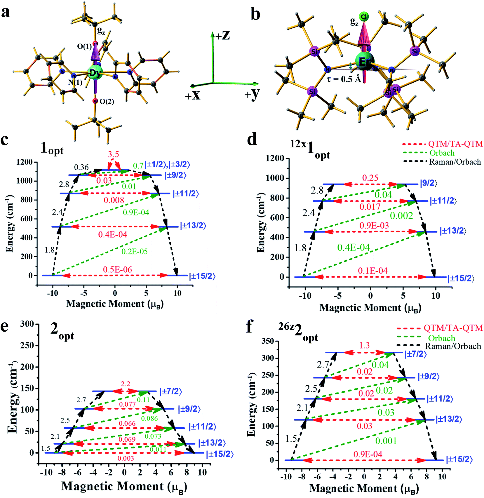 | ||
| Fig. 1 Optimised geometries and ab initio blocking barriers at different external electric fields: structures of (a) 1opt and (b) 2opt, along with the computed gz-axis. Colour code: Dy – cyan, Er – dark cyan, N – blue, Cl – green, Si – pink, C – grey, and H – light grey. Ab initio blocking barriers and relaxation mechanisms of complexes (c) 1opt, (d) 12x1opt, (e) 2opt and (f) 26z2opt. For figures c-f, the red arrows indicate the QTM or TA-QTM via ground or excited KDs, respectively. The blue characters indicate the major components of mJ of a KD. The green dotted arrows show the mechanisms of the Orbach processes. The black arrows indicate the pathways of magnetic relaxation. | ||
In the next step, we attempted to optimise the geometry in the presence of an oriented external electric field (OEEF) starting from 0.004 au (atomic unit, equivalent to 0.2 V Å−1).10c,13 The electric field applied here varied from 0.004 au to 0.026 au and lies within the limits of ionisation energies and bond dissociation energies, and is accessible for most of the STM tips.13,14 While the electric field-induced spectroscopic techniques use a smaller field, organic reactions that are performed using an OEFF are comparable to the electric field utilised here.13,14 Applying the electric field along the +z-axis (which is co-linear with the gz axis for complex 1) in 1opt (see Fig. 1a, b and S1 in the ESI†) elongates the Dy–O(1) bond and, at the same time, shortens the Dy–O(2) bond, and therefore breaks the pseudo-D5h symmetry of the molecule. We performed ab initio CASSCF calculations on this optimised geometry for 4z1opt (here, the superscript denotes the amount of OEEF applied × 10−3 au along the +z direction) in the presence of an electric field (EF), wherein a reduction in the barrier height was witnessed. This is due to the fact that Dy–O(1) bond elongation causes weakening of the axial LF and hence reduces the axial anisotropy for the oblate Dy(III) ion. Although a simultaneous shortening of the Dy–O(2) bond is seen, the 4z1opt geometry reveals that elongation is larger than the shortening (see Fig. S1†). This asymmetric distortion leads to a smaller Ucal value of 1108 cm−1 for 4z1opt. In the next step, we increased the OEEF value in a stepwise manner to 0.012 au, and could clearly see that an increase in the electric field increases the Dy–O(1) bond further and, at the same time, shortens the Dy–O(2) bond, albeit asymmetrically. This led to a further reduction in the barrier height, with a value of 1040 cm−1 noted for the 12z1opt structure (see Tables S6 and S9–S11 in the ESI†). This reduction in the barrier height can be rationalised by analysing the LoProp charges at the spin-free ground state. By increasing OEEF, the LoProp charge on O(1) gradually decreases, while it is increased on O(2) (see Tables S8 and S16†). Perceiving this effect, we switched the OEEF along the x/y direction for complex 1opt (see Fig. S1 in the ESI†), and this yields structure of 4x1opt (here, the superscript denotes the amount of OEEF applied × 10−3 au along the +x direction). Here, the Dy–N(1) bond length was found to increase sharply from 2.62 Å to 2.80 Å, vis-à-vis, the geometries of 1optvs.12x1opt (see Table 1) and, at the same time, two of the Dy–N bonds (along the −x-direction) were found to shorten asymmetrically. Also, the effect of applying an OEEF along the Dy–N(1) direction could be seen by a substantial decrease in the LoProp charge of the N(1) atom, while the charges on the oxygen atoms remained unaltered (see Table S8 in the ESI†). As three Dy–N bonds were significantly elongated in the geometry of the 12x1opt complex, it could be expected to possess a large barrier height. However, ab initio calculations revealed the contrary, with the barrier height diminishing with an increase in OEEF value, yielding a Ucal value of 939 cm−1 for 12x1opt, and this relaxes via 3rd excited KDs (see Tables S7 and S12–S14 in the ESI†). This is due to the fact that an alteration of the Dy–N distances is accompanied by a variation in the ∠O–Dy–O angle, which is reduced to 157° in 12x1opt from 178° in the geometry of 1opt (see Table 1). Thus, the application of the electric field along the perpendicular or gx-direction decreases the barrier height in complex 1. In addition, in both directions (x or z), the ground state as well as the excited state, the QTM (quantum tunnelling of magnetisation) values increase for complex 1, further supporting the reduction in the Ucal values. To prove that the reduction is solely due to the ∠O–Dy–O angle bending, we performed one additional set of calculations on the geometry of 12x1opt, where the ∠O–Dy–O angle was fictitiously set at 178° and this structure yielded a barrier height of 1162 cm−1 (see Fig. S2 and Table S15 in the ESI†). This estimated value is ∼50 cm−1 higher, compared to the optimised geometry, offering a possibility, however small, of enhancing the Ucal value in 1 using an applied electric field. Furthermore, increasing the OEEF to 0.016 au resulted in dissociation of the Dy–N bond, and this sets the electric field limit in the x/y direction of the molecule.
To further understand how the alteration of the structure occurs due to the applied OEEF, it is important to understand the nature of dipoles and their behaviour in the applied electric field conditions. The application of an OEEF is expected to polarise a non-polar bond and enhance the ionic character of a polar bond.13 For a Ln–L bond, the application of an OEEF will stretch it further if the dipolar field creates an opposite dipole with respect to the Ln–L dipole, and will shorten it if the dipolar field is in the same direction as the Ln–L dipole (see Fig. 2a). Therefore, the molecule has to be chosen in such a way that an increase in the Ln–L bond length will enhance the magnetic anisotropy and will subsequently increase the barrier height (Ueff).
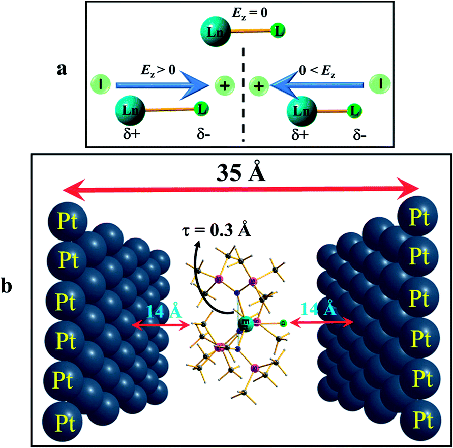 | ||
| Fig. 2 Arrangement of the application of an external electric field. (a) Result of applying an OEEF on a polar Ln–L bond axis. (b) Arrangement of applying an external electric field by placing point charges on two opposite Pt (111) layers that are 35 Å apart, and the molecule is at the centre, during ab initio calculations (the distance between the molecule to the Pt layers is not to scale). For more information see the computational details. | ||
Applying an OEEF along an equatorial Ln–L bond in oblate ions, such as Dy(III), or along an axial Ln–L bond in prolate ions, such as Er(III), is thus likely to increase the Ueff value beyond the reported values from the X-ray structures. However, if the OEEF is applied along the opposite directions, it is expected to further decrease the Ueff values.
Based on the knowledge gained, we intuitively expanded the study to a prolate Er(III) ion using complex 2. We narrowed it down to this example for two reasons: (i) to choose a well-studied prolate Er(III) SIM with a significant barrier height, and (ii) to choose an Er(III) SIM with a strong equatorial ligand and a weak axial ligand along only one direction, as this would be expected to facilitate the enhancement of the Ucal value upon application of an OEEF. Upon application of the OEEF along the Er–Cl direction (gz axis, see Fig. 2b), with the same step-size as before, the Er–Cl bond length was found to increase significantly (see Fig. S3 in the ESI† and Table 1), reaching a value of 2.91 Å at 0.024 au EZ (24z2Opt). To determine the tolerance limit, we further increased the electric field to 0.026 au EZ (26z2Opt) and found that the Er–Cl bond length elongated further to 3.04 Å. The application of an OEEF beyond this value was found to cleave the Er–Cl bond, suggesting a possible ionisation/decomposition limit.
Additionally, the {N3Er} out-of-plane pyramidal shift (parameter τ, see Fig. 2 and S3 in the ESI†) was also found to change upon application of the OEEF. As the OEEF was applied along the Er–Cl bond, this bond elongates and pushes the Er(III) ion down, and therefore decreases the τ value. The τ value decreased from 0.5 Å in the 2opt complex to 0.3 Å at 26z2opt. If the OEEF was applied along the −z-direction (Cl–Er direction), this tended to enhance the pyramidalisation (see Fig. S3 in the ESI†) and, thus, the τ value increased to 0.62 Å at 26-z2opt. Theoretical studies performed earlier on complex 2 revealed that this is an important parameter that enhances the barrier height.15
The application of an OEEF along the gz axis in 2 (i.e. along the Er–Cl bond) enhanced the value of Ucal from 163 cm−1 at 4z2opt to a remarkable 317 cm−1 at 26z2opt. This estimate is one of the highest obtained for any Er(III) SIMs.16 Computed QTM (and TA-QTM) values revealed a smooth decrease of these values from 2.2 μB at 4z2opt to 1.3 μB at 26z2opt (see Tables S17–S24 in the ESI†). In addition, a smooth linear increase of the negative B20 parameter was observed for complex 2 under the applied electric field range along the +z direction (see Fig. S4 and Table S27 in the ESI†). If an OEEF was applied in the reverse direction on complex 2, i.e. along the −z-direction, a reverse trend was visible, with a gradual decrease in the Ucal value. As expected, here the Er(III)–Cl bond length decreased and a decrease in the τ value was noticed upon application of an electric field in the −z-direction. The Ucal value decreased from 131 cm−1 for 4-z2opt to the much smaller value of 52 cm−1 (via the 3rd excited state) for the 24-z2opt structure (see Tables S25–S27 in the ESI†). Furthermore, the Ucal value diminishes to zero for 26-z2opt, with a notable ground state QTM. We also plotted the β-electron density of Er(III) under the applied electric field conditions, and this reflects well with the observed changes (see Fig. S5† for a plot corresponding to 26-z2opt, 2opt and 26z2opt).
After achieving such a large Ucal value for complex 2, we extended the study further to another Dy(III) example, namely [Dy(CpMe3)2Cl] (complex 3) (CpMe3 = trimethylcyclopentadienyl) (see Fig. 3a), which is a model complex derived from the X-ray structure of the famous precursor, [Dy(Cpttt)2Cl].3a The calculations on the optimised structure (3opt) revealed a very small Ucal value of 144 cm−1 relaxing via the first excited state due to high QTM being in operation due to the coordination of –Cl along the equatorial direction (see Tables S28 and S29 in the ESI†). In order to quench this QTM, we applied the OEEF along the Dy–Cl bond direction (perpendicular to the gz axis), and this led to the weakening of the Dy–Cl bond and a gradual increase in the Ucal value from 160 cm−1 at 4z3opt (here the +z direction indicates application of OEEF along the Dy–Cl bond axis) to 519 cm−1 in the 22z3opt structure (see Table S29† and Fig. 3a–d). The Dy–Cl bond length increased from 2.59 Å for 4z3opt to 2.94 Å for 22z3opt. As the Dy–Cl bond distance increases with the applied electric field, two other important structural parameters were also found to have been altered. Firstly, the distance between the two Cp rings was found to decrease and, secondly, the Cp–Dy–Cp angle was found to increase (see Table S28 in the ESI†). The application of an electric field beyond 0.022 au resulted in the rupture of the Dy–Cl bond. At the 22z3opt geometry, the Ucal value estimated is found to be three times larger than the optimized structure obtained in the absence of OEEF (3opt).
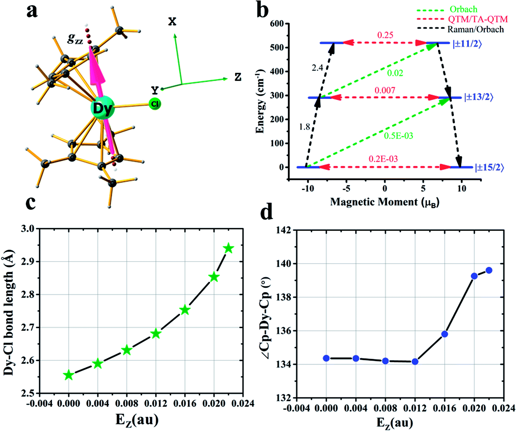 | ||
| Fig. 3 Details of the application of an external electric field in complex 3. (a) DFT optimised geometry of complex 3, along with the gzz axis and the three cartesian axes directions. (b) An ab initio computed magnetization blocking barrier diagram of 22z3opt. See Fig. 1 caption for further details. (c) Variations in the Dy–Cl bond length and (d) Cp–Dy–Cp angle with respect to the oriented external electric field. | ||
While the QTM (or TA-QTM) probabilities have been found to alter upon the application of an electric field, the challenge of controlling the blocking temperature still remains. As the electric field modifies the geometry, this in turn alters the corresponding molecular vibrations and hence offers a way to control the molecular vibrations that are responsible for magnetisation relaxation. This idea can be utilised to modulate the prominent vibrations that are responsible for the reduction in the blocking temperature, and work in this direction is currently underway in our laboratory.
Conclusions
As chemical fine-tuning of the ligand field has already reached its potential, here we set out to search for an alternative route to enhance the Ueff values in Ln(III) SIMs. In this context, we explored the role of an applied external electric field in the magnetisation reversal in [Dy(Py)5(OtBu)2]+ (1), [Er{N(SiMe3)2}3Cl]− (2), and [Dy(CpMe3)2Cl] (3) single-ion magnets. Our calculations revealed a moderate improvement in the Ucal value of 1 if the electric field was applied along the gx direction. Learning from this example, we studied the [Dy(CpMe3)2Cl] complex, where the application of an electric field along the Dy–Cl direction was found to weaken the Dy–Cl bond, leading to an enhancement of the barrier height by three times (it was increased from 144 cm−1 at a 0.004 au electric field to a remarkable 519 cm−1 at a 0.022 au electric field), compared to the original molecule. Based on these understandings, we intuitively studied [Er{N(SiMe3)2}3Cl]−, where the application of an electric field along the Er–Cl gz-direction was found to boost the barrier height twice that of the reported Ueff values. The enhancement in the Ucal value was much larger than that of the X-ray structures, offering a viable non-chemical method to enhance the barrier height beyond the limits set by the ligand fields. This novel approach is expected to generate substantial interest in obtaining new generation SIMs, unveiling its potential applications.Computational details
DFT calculations
All the geometry optimisations were performed with DFT (Density Functional Theory) calculations using the Gaussian 09 package (revision D.01).17 During geometry optimisations, we replaced the central Dy(III) and Er(III) ions with a diamagnetic Y(III) ion, as this ion has a similar ionic radius. The hybrid B3LYP functional, along with the SDD basis set18 and corresponding ECP basis set for Y and the Ahlrichs split-valence polarisation (SVP)19 for the rest of the atoms were used during the optimisation steps. In addition, the diffused 6-31+G(d,p) basis set was tested and used for the non-metals and compared with the SVP results. The geometrical parameters were found not to change upon changing the basis set from SVP to 6-31+G(d,p). An oriented external electric field (OEEF) was applied during the optimisation in a particular direction using the Field keyword available in G09 suite. The OEEF was increased with a step-size of a 0.004 au electric field, which is equivalent to 0.2 V Å−1 (1 au = 51.4 V Å−1).Ab initio calculations
After the geometry optimisation at different electric fields, the optimised complexes were inserted between the Platinum (Pt) layers for single point CASSCF calculations. Here, in the ab initio setup, the central metal ion was placed back into the original lanthanide centres to perform anisotropy calculations in the presence of the external electric field. Since the OEEF was applied along a particular direction during the DFT calculations, a similar orientation was fixed during the ab initio setup as well. All the ab initio single point calculations were performed using the MOLCAS 8.0 program package.20 Here, a multi-configurational CASSCF (complete active space self-consistent field) method was chosen to compute the spin-Hamiltonian parameters. We employed relativistic contracted atomic natural orbital type basis sets: [ANO-RCC-VTZP…8s7p5d3f2g1h] for Ln(III) {Ln = Dy, Er}, ANO-RCC-VDZP (ANO-RCC…6s5p3d1f) for Si and Cl, ANO-RCC-VDZP (ANO-RCC…3s2p1d) for N and O, ANO-RCC-VDZ (ANO-RCC…3s2p) and ANO-RCC-VDZP (in the case of complex 3) for C, and ANO-RCC-VDZ (ANO-RCC…2s) for H, throughout our calculations. First, we performed a simple low-level SCF to generate the starting estimated orbitals in the Guessorb step. The Pt(111) layer was introduced as point charges to generate the external static electric field using the XFIELD keyword available in MOLCAS suite. In order to generate the external electric field for the ab initio calculations in MOLCAS, we placed two oppositely charged single Pt(111) layers, each containing 39 Pt atoms of dimension 14 × 14 (Å),2 on each side and at 35 Å apart (see Fig. 2b in the main manuscript). Point charges of the different signs were imposed on the opposite Pt(111) layers to generate the electric field, mimicking the electrode setup. Then, in this arrangement, the optimised DyIII/ErIII complex was placed exactly at the centre of the two Pt(111) layers. It was assumed that no chemical interaction was possible between the two layers and the molecule, as the distance is too high (∼15 Å). More precisely, the electric field was directed perpendicular to the Pt layers. The direction of the electric field could be switched by altering the sign of the charges on the Pt(111) layers. The charges were chosen in a trial and error method, so that the generated electric field matched exactly with the oriented electric field used earlier during optimisation in DFT. The imposed point charges and the corresponding generated electric fields at the origin or centre of the Pt layer were calculated and are listed in Tables S6 and S7.†The AMFI (atomic mean field integral) spin–orbit operator was introduced to account for the spin–orbit effects. The scalar relativistic effect was considered using the DKH Hamiltonian. The Cholesky decomposition method was adopted to accelerate the two-electron integral calculation. In the configuration interaction (CI) step (CASSCF), an active space of 9 electrons in seven 4f orbitals, i.e. CAS(9,7) for Dy; 11 electrons in seven 4f orbitals, i.e. CAS(11,7) for Er(III) were considered throughout the calculations. This active space was optimised with 21 sextets for Dy(III), and 35 quartets and 112 doublets for Er(III). The spin–orbit coupling was taken into account using the RASSI-SO (Restricted Active Space State Interaction Spin–Orbit) module, which acts on all the spin-free states generated from the CASSCF wavefunctions. Finally, eight lower energy ground state Kramer doublets (KDs) for Dy(III) and Er(III) were used for the calculation of the spin-Hamiltonian properties, such as the g tensor values, using a specially designed routine SINGLE-ANISO module.
Crystal field description
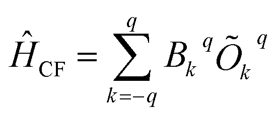
The crystal field Hamiltonian for lanthanide coordination complexes has been defined as follows,where Bkq and Okq are the extended crystal field (CF) operator and the Stevens operator, respectively. Here, if the value of k is 2, then Bkq is the tensor quantity, and k = 2 (higher-order indices like 4, 6,… are also possible), where q = 0 denotes an axial crystal field and a non-zero value of q denotes a non-axial crystal field.21 Therefore, a large negative Bk=2,4…q=0 value with a very small Bk=2,4…q≠0 value indicates axial anisotropy and the reverse situation indicates transverse magnetic anisotropy.
Conflicts of interest
There are no conflicts to declare.Acknowledgements
AS thanks CSIR for the senior research fellowship (SRF) and GR would like to thank DST (DST/SJF/CSA-03/2018-10) and SERB (CRG/2018/000430; SB/SJF/2019-20/12) for funding.References
- (a) R. Sessoli, D. Gatteschi, A. Caneschi and M. Novak, Nature, 1993, 365, 141–143 CrossRef CAS; (b) M. N. Leuenberger and D. Loss, Nature, 2001, 410, 789–793 CrossRef CAS; (c) S. Sanvito, Chem. Soc. Rev., 2011, 40, 3336–3355 RSC; (d) E. Moreno-Pineda, C. Godfrin, F. Balestro, W. Wernsdorfer and M. Ruben, Chem. Soc. Rev., 2018, 47, 501–513 RSC.
- (a) Y. S. Ding, N. F. Chilton, R. E. Winpenny and Y. Z. Zheng, Angew. Chem., Int. Ed., 2016, 55, 16071–16074 CrossRef CAS; (b) S. K. Gupta, T. Rajeshkumar, G. Rajaraman and R. Murugavel, Chem. Sci., 2016, 7, 5181–5191 RSC; (c) J. Liu, Y.-C. Chen, J.-L. Liu, V. Vieru, L. Ungur, J.-H. Jia, L. F. Chibotaru, Y. Lan, W. Wernsdorfer and S. Gao, J. Am. Chem. Soc., 2016, 138, 5441–5450 CrossRef CAS.
- (a) C. A. P. Goodwin, F. Ortu, D. Reta, N. F. Chilton and D. P. Mills, Nature, 2017, 548, 439–442 CrossRef CAS; (b) F.-S. Guo, B. M. Day, Y.-C. Chen, M.-L. Tong, A. Mansikkamäki and R. A. Layfield, Science, 2018, 362, 1400–1403 CrossRef CAS; (c) F. S. Guo, B. M. Day, Y. C. Chen, M. L. Tong, A. Mansikkamäki and R. A. Layfield, Angew. Chem., Int. Ed., 2017, 56, 11445–11449 CrossRef CAS; (d) K. R. McClain, C. A. Gould, K. Chakarawet, S. J. Teat, T. J. Groshens, J. R. Long and B. G. Harvey, Chem. Sci., 2018, 9, 8492–8503 RSC; (e) P. Evans, D. Reta, G. F. Whitehead, N. F. Chilton and D. P. Mills, J. Am. Chem. Soc., 2019, 141, 19935–19940 CrossRef CAS; (f) C. A. Gould, K. R. McClain, J. M. Yu, T. J. Groshens, F. Furche, B. G. Harvey and J. R. Long, J. Am. Chem. Soc., 2019, 141, 12967–12973 CrossRef CAS.
- (a) J. D. Rinehart, M. Fang, W. J. Evans and J. R. Long, Nat. Chem., 2011, 3, 538–542 CrossRef CAS; (b) S. G. McAdams, A.-M. Ariciu, A. K. Kostopoulos, J. P. Walsh and F. Tuna, Coord. Chem. Rev., 2017, 346, 216–239 CrossRef CAS.
- (a) Y.-Z. Zheng, Y.-S. Ding, T. Han, Y.-Q. Zhai, D. Reta, N. F. Chilton and R. E. Winpenny, Chem.–Eur. J., 2020, 26, 5893–5902 CrossRef; (b) K.-X. Yu, J. G. C. Kragskow, Y.-S. Ding, Y.-Q. Zhai, D. Reta, N. F. Chilton and Y.-Z. Zheng, Chem, 2020, 6, 1777–1793 CrossRef; (c) A. Castro-Alvarez, Y. Gil, L. Llanos and D. Aravena, Inorg. Chem. Front., 2020, 7, 2478–2486 RSC; (d) B. Yin and C. C. Li, Phys. Chem. Chem. Phys., 2020, 22, 9923–9933 RSC; (e) A. Chiesa, F. Cugini, R. Hussain, E. Macaluso, G. Allodi, E. Garlatti, M. Giansiracusa, C. A. P. Goodwin, F. Ortu, D. Reta, J. M. Skelton, T. Guidi, P. Santini, M. Solzi, R. De Renzi, D. P. Mills, N. F. Chilton and S. Carretta, Phys. Rev. B, 2020, 101, 174402 CrossRef CAS.
- D. N. Woodruff, R. E. Winpenny and R. A. Layfield, Chem. Rev., 2013, 113, 5110–5148 CrossRef CAS.
- A. B. Canaj, S. Dey, E. R. Martí, C. Wilson, G. Rajaraman and M. Murrie, Angew. Chem., 2019, 131, 14284–14289 CrossRef.
- A. Upadhyay, S. K. Singh, C. Das, R. Mondol, S. K. Langley, K. S. Murray, G. Rajaraman and M. Shanmugam, Chem. Commun., 2014, 50, 8838–8841 RSC.
- M. K. Singh, N. Yadav and G. Rajaraman, Chem. Commun., 2015, 51, 17732–17735 RSC.
- (a) A. S. Zyazin, J. W. van den Berg, E. A. Osorio, H. S. van der Zant, N. P. Konstantinidis, M. Leijnse, M. R. Wegewijs, F. May, W. Hofstetter, C. Danieli and A. Cornia, Nano Lett., 2010, 10, 3307–3311 CrossRef CAS; (b) T. Goswami and A. Misra, Chem.–Eur. J., 2014, 20, 13951–13956 CrossRef CAS; (c) A. Palii, S. Aldoshin and B. Tsukerblat, J. Phys. Chem. C, 2017, 121, 27218–27224 CrossRef CAS; (d) M. Fittipaldi, A. Cini, G. Annino, A. Vindigni, A. Caneschi and R. Sessoli, Nat. Mater., 2019, 18, 329–334 CrossRef CAS; (e) J. Liu, J. Mrozek, W. K. Myers, G. A. Timco, R. E. P. Winpenny, B. Kintzel, W. Plass and A. Ardavan, Phys. Rev. Lett., 2019, 122, 037202 CrossRef CAS; (f) A. K. Boudalis, J. Robert and P. Turek, Chem.–Eur. J., 2018, 24, 14896–14900 CrossRef CAS; (g) M. Weisheit, S. Fähler, A. Marty, Y. Souche, C. Poinsignon and D. Givord, Science, 2007, 315, 349–351 CrossRef CAS.
- A. J. Brown, D. Pinkowicz, M. R. Saber and K. R. Dunbar, Angew. Chem., Int. Ed., 2015, 54, 5864–5868 CrossRef CAS.
- S. K. Singh, B. Pandey, G. Velmurugan and G. Rajaraman, Dalton Trans., 2017, 46, 11913–11924 RSC.
- S. Shaik, R. Ramanan, D. Danovich and D. Mandal, Chem. Soc. Rev., 2018, 47, 5125–5145 RSC.
- (a) C. Wang, D. Danovich, H. Chen and S. Shaik, J. Am. Chem. Soc., 2019, 141, 7122–7136 CrossRef CAS; (b) X. Huang, C. Tang, J. Li, L.-C. Chen, J. Zheng, P. Zhang, J. Le, R. Li, X. Li and J. Liu, Sci. Adv., 2019, 5, eaaw3072 CrossRef CAS; (c) A. B. Zakharov, V. V. Ivanov and L. Adamowicz, Int. J. Quantum Chem., 2020, e26260 CAS.
- S. K. Singh, T. Gupta, M. Shanmugam and G. Rajaraman, Chem. Commun., 2014, 50, 15513–15516 RSC.
- (a) M. J. Heras Ojea, L. C. Maddock and R. A. Layfield, Organometallic Magnets, 2019, pp. 253–280 Search PubMed; (b) T. Gupta, M. K. Singh and G. Rajaraman, in Organometallic Magnets, Springer, 2018, pp. 281–354 Search PubMed; (c) A. Swain, A. Sarkar and G. Rajaraman, Chem.–Asian J., 2019, 14, 4056–4073 CrossRef CAS.
- M. J. Frisch, G. W. Trucks, H. B. Schlegel, G. E. Scuseria, M. A. Robb, J. R. Cheeseman, G. Scalmani, V. Barone, B. Mennucci, G. A. Petersson, H. Nakatsuji, M. Caricato, X. Li, H. P. Hratchian, A. F. Izmaylov, J. Bloino, G. Zheng, J. L. Sonnenberg, M. Hada, M. Ehara, K. Toyota, R. Fukuda, J. Hasegawa, M. Ishida, T. Nakajima, Y. Honda, O. Kitao, H. Nakai, T. Vreven, J. A. Montgomery Jr, J. E. Peralta, F. Ogliaro, M. Bearpark, J. J. Heyd, E. Brothers, K. N. Kudin, V. N. Staroverov, T. Keith, R. Kobayashi, J. Normand, K. Raghavachari, A. Rendell, J. C. Burant, S. S. Iyengar, J. Tomasi, M. Cossi, N. Rega, J. M. Millam, M. Klene, J. E. Knox, J. B. Cross, V. Bakken, C. Adamo, J. Jaramillo, R. Gomperts, R. E. Stratmann, O. Yazyev, A. J. Austin, R. Cammi, C. Pomelli, J. W. Ochterski, R. L. Martin, K. Morokuma, V. G. Zakrzewski, G. A. Voth, P. Salvador, J. J. Dannenberg, S. Dapprich, A. D. Daniels, O. Farkas, J. B. Foresman, J. V. Ortiz, J. Cioslowski, and D. J. Fox, Gaussian 09, Revision D.01, Wallingford CT, 2013 Search PubMed.
- T. H. Dunning and P. J. Hay, in Modern theoretical chemistry, Plenum Press, New York, 1977, vol. 3, p. 1 Search PubMed.
- A. Schäfer, C. Huber and R. Ahlrichs, J. Chem. Phys., 1994, 100, 5829–5835 CrossRef.
- F. Aquilante, J. Autschbach, R. K. Carlson, L. F. Chibotaru, M. G. Delcey, L. De Vico, N. Ferré, L. M. Frutos, L. Gagliardi and M. Garavelli, J. Comput. Chem., 2016, 37, 506–541 CrossRef CAS.
- C. Rudowicz, J. Phys. C: Solid State Phys., 1985, 18, 1415 CrossRef.
Footnote |
| † Electronic supplementary information (ESI) available. See DOI: 10.1039/d0sc03982a |
| This journal is © The Royal Society of Chemistry 2020 |