
 Open Access Article
 This Open Access Article is licensed under a Creative Commons Attribution-Non Commercial 3.0 Unported Licence
Conservation of structural arrangements and 3![[thin space (1/6-em)]](https://www.rsc.org/images/entities/h2_char_2009.gif) :1 stoichiometry in a series of crystalline conductors of TMTTF, TMTSF, BEDT-TTF, and chiral DM-EDT-TTF with the oxo-bis[pentafluorotantalate(V)] dianion†
:1 stoichiometry in a series of crystalline conductors of TMTTF, TMTSF, BEDT-TTF, and chiral DM-EDT-TTF with the oxo-bis[pentafluorotantalate(V)] dianion†
Nabil
Mroweh
a,
Cécile
Mézière
a,
Magali
Allain
a,
Pascale
Auban-Senzier
b,
Enric
Canadell
 *c and
Narcis
Avarvari
*a
*c and
Narcis
Avarvari
*a
aMOLTECH-Anjou, UMR 6200, CNRS, UNIV Angers, 2 bd Lavoisier, 49045 ANGERS Cedex, France. E-mail: narcis.avarvari@univ-angers.fr
bLaboratoire de Physique des Solides, Université Paris-Saclay, CNRS UMR 8502, 91405 Orsay, France
cInstitut de Ciència de Materials de Barcelona (CSIC), Campus de la UAB, E-08193 Bellaterra, Spain. E-mail: canadell@icmab.es
First published on 13th August 2020
Abstract
The occurrence of isostructural conducting radical cation salts of diversely substituted tetrathiafulvalene (TTF) precursors with the same anion is most often limited to very similar derivatives such as tetramethyl-tetrathiafulvalene (TMTTF) and tetramethyl-tetraselenafulvalene (TMTSF). Here we show that the use of the oxo-bis[pentafluorotantalate(V)] dianion [Ta2F10O]2− affords upon electrocrystallization of TMTTF, TMTSF, bis(ethylenedithio)-tetrathiafulvalene (BEDT-TTF), racemic dimethyl-ethylenedithio-tetrathiafulvalene ((rac)-DM-EDT-TTF), and enantiopure (S,S)-DM-EDT-TTF a series of mixed valence crystalline radical cation salts with the same 3![[thin space (1/6-em)]](https://www.rsc.org/images/entities/char_2009.gif) :1 stoichiometry. The donor layers show similar features in the five materials, such as alternation of trimeric units within stacks which arrange in parallel columns of β-type. The anion arranges either parallel or perpendicular to the stack direction and establishes numerous intermolecular CH⋯F hydrogen bonds. Thus, the [Ta2F10O]2− dianion, most likely because of its shape and propensity to engage in hydrogen bonding, is the first one to be able to induce the same type of structural arrangement for a broad series of different donors, a result which is important in the crystal engineering of molecular conductors. All the compounds are band gap semiconductors, according to single crystal resistivity measurements and extended Hückel band structure calculations. The room temperature conductivity values are relatively high, i.e. 0.25–1.1 S cm−1, except for the TMTTF salt, whose conductivity value is two orders of magnitude smaller than its isostructural TMTSF counterpart, in agreement with the band gap energy value. As a general feature of these materials, variations in the inter- and intra-trimer interactions modulate their band structure, i.e. energy dispersion and band gaps. The preparation of this series of radical cation salts with a sturdy 3:1 stoichiometry might question previous assignments of the anion as [Ta2F11]− in radical cation salts of TMTSF and BEDT-TTF.
:1 stoichiometry. The donor layers show similar features in the five materials, such as alternation of trimeric units within stacks which arrange in parallel columns of β-type. The anion arranges either parallel or perpendicular to the stack direction and establishes numerous intermolecular CH⋯F hydrogen bonds. Thus, the [Ta2F10O]2− dianion, most likely because of its shape and propensity to engage in hydrogen bonding, is the first one to be able to induce the same type of structural arrangement for a broad series of different donors, a result which is important in the crystal engineering of molecular conductors. All the compounds are band gap semiconductors, according to single crystal resistivity measurements and extended Hückel band structure calculations. The room temperature conductivity values are relatively high, i.e. 0.25–1.1 S cm−1, except for the TMTTF salt, whose conductivity value is two orders of magnitude smaller than its isostructural TMTSF counterpart, in agreement with the band gap energy value. As a general feature of these materials, variations in the inter- and intra-trimer interactions modulate their band structure, i.e. energy dispersion and band gaps. The preparation of this series of radical cation salts with a sturdy 3:1 stoichiometry might question previous assignments of the anion as [Ta2F11]− in radical cation salts of TMTSF and BEDT-TTF.
1. Introduction
Among tetrathiafulvalene (TTF) and tetraselenafulvalene (TSF) based conducting materials,1,2 Bechgaard and Fabre salts, that is (TMTSF)2X and (TMTTF)2X (TM = tetramethyl, X = PF6−, AsF6−, SbF6−, TaF6−, ClO4−, etc.), respectively, occupy a special place,3–6 as the former provided the first superconducting organic materials under moderate pressures,7,8 while the latter show charge ordering.9 However, later on, superconductivity has been observed as well in the (TMTTF)2XF6 (X = P, As, Sb) series for pressures above 4.5 GPa.10–12 Particularly interesting is the evolution of the critical temperature Tc for the superconducting transition with the applied pressure and the anion size in the (TMTSF)2XF6 Bechgaard salts8,13,14 and also the variation of the charge ordering transition temperature TCO in the Fabre salts (TMTTF)2XF6 (X = P, As, Sb, Ta) with the anion size, as a consequence of the chemical pressure exerted by the anion.15 For example, TCO values are 65 K, 100 K, 155 K and 175 K for PF6−, AsF6−, SbF6− and TaF6−, respectively.15 Interestingly, while Bechgaard and Fabre salts are isostructural,5,13,16 2:1 mixed valence salts of bis(ethylenedithio)-tetrathiafulvalene (BEDT-TTF), another flagship donor in the field of organic conductors and superconductors,2,17,18 with octahedral monoanions XF6− show, in comparison, a rich collection of structures and, consequently, physical properties. Indeed, triclinic and orthorhombic phases have been described for α-(BEDT-TTF)2PF619 and β-(BEDT-TTF)2PF6,20 respectively, monoclinic21 and orthorhombic22 structures for β-(BEDT-TTF)2AsF6, a monoclinic phase for β-(BEDT-TTF)2SbF6,23 isostructural to the AsF6− counterpart, and, finally, monoclinic and orthorhombic structures for δ-(BEDT-TTF)2TaF6,24 together with a monoclinic κ-(BEDT-TTF)2TaF6 phase.25 In the course of our own investigations on chiral conductors,26,27 culminating with the first experimental observation of the electrical magnetochiral anisotropy effect (eMChA),28 we observed as well a strong dependence of the donor packing on the anion size in the (DM-EDT-TTF)2XF6 series (DM-EDT-TTF = dimethyl-ethylenedithio-TTF, Scheme 1, X = P, As, Sb).
 | ||
| Scheme 1 TTF donors employed in this work. | ||
While the semiconducting enantiopure (S,S) and (R,R) (DM-EDT-TTF)2PF6 salts crystallize in the monoclinic space group P21, the racemic counterpart crystallizes in triclinic P![[1 with combining macron]](https://www.rsc.org/images/entities/char_0031_0304.gif) and shows metallic conductivity in the high temperature regime, followed by a Mott localization below 110 K.29,30 The compounds (DM-EDT-TTF)2SbF6 are isostructural with the racemic PF6− salt, that is triclinic P for the racemic and P1 for the enantiopure salts, and show metal-like behaviour.31 Interestingly, for the intermediate size anion AsF6−, both monoclinic and triclinic phase (DM-EDT-TTF)2AsF6 have been obtained for the enantiopure donors, thus illustrating the crucial role of the anion size through its propensity to engage in intermolecular hydrogen bonding with the donors. Moreover, reducing the number of stereogenic centres in the Me-EDT-TTF donor induced the crystallization of the metallic enantiopure and racemic triclinic phase (Me-EDT-TTF)2PF6,32 isostructural to [(rac)-DM-EDT-TTF]2PF6, thus indicating that small structural modifications of the donor can lead, however, to different crystal structures in spite of keeping the same anion.
and shows metallic conductivity in the high temperature regime, followed by a Mott localization below 110 K.29,30 The compounds (DM-EDT-TTF)2SbF6 are isostructural with the racemic PF6− salt, that is triclinic P for the racemic and P1 for the enantiopure salts, and show metal-like behaviour.31 Interestingly, for the intermediate size anion AsF6−, both monoclinic and triclinic phase (DM-EDT-TTF)2AsF6 have been obtained for the enantiopure donors, thus illustrating the crucial role of the anion size through its propensity to engage in intermolecular hydrogen bonding with the donors. Moreover, reducing the number of stereogenic centres in the Me-EDT-TTF donor induced the crystallization of the metallic enantiopure and racemic triclinic phase (Me-EDT-TTF)2PF6,32 isostructural to [(rac)-DM-EDT-TTF]2PF6, thus indicating that small structural modifications of the donor can lead, however, to different crystal structures in spite of keeping the same anion.
In view of these results we became interested in the use of the largest anion in the series, that is hexafluorotantalate TaF6−, but also of the even bigger bis-octahedral congener undecafluorotantalate [Ta2F11]− in combination with our chiral donor DM-EDT-TTF (Scheme 1). The case of the latter anion looked particularly intriguing, first because radical cation salts with TMTSF and BEDT-TTF, formulated as (TMTSF)3Ta2F1133 and (BEDT-TTF)3Ta2F11,34,35 were reported during the “rush” period towards the highest Tc in organic superconductors, in 1980–1990. Second, although we could not find many structural and experimental details on these two salts, especially on the latter, for which no preparation conditions are provided in the literature, the donors seem to show very similar packings with the formation of trimers along the donor stacks. The formation of [Ta2F11]− in the case of (TMTSF)3Ta2F11 was reported to occur serendipitously, since the authors mentioned the use of (n-Bu4N)TaF6 as the anion source. Note, however, that reports in the literature on other [Ta2F11]− based salts are very scarce. While Brownstein mentioned that attempts to isolate (n-Bu4N)Ta2F11 in the solid state failed in spite of 19F NMR evidence of its existence in solution,36 Pampaloni et al.37 described the single crystal X-ray structure of a [Ta2F11]− salt with the 1,3-dimethoxy-benzene radical cation, and Tavčar et al.38 crystallized one-dimensional coordination polymers of Hg2+ and Cd2+, where [Ta2F11]− units act as bridging ligands through terminal fluorine atoms. These compounds have been prepared under strictly anhydrous, oxygen free conditions and even in anhydrous HF for the latter, suggesting that the occurrence of [Ta2F11]− in the solid state requires special care.
We describe herein our attempts to prepare radical cation salts of fluorotantalate anions not only with the “classical” donors TMTSF, TMTTF and BEDT-TTF, but also with the chiral donor DM-EDT-TTF, which resulted in an unprecedented robust series of isostructural mixed valence salts of 3:1 stoichiometry. Electron transport properties have been investigated for all the compounds together with tight-binding band structure calculations.
2. Results and discussion
2.1 Synthetic routes towards hexafluorotantalate and oxo-bis(pentafluorotantalate) anions
Since our initial purpose was to complete the series of chiral radical cation salts (DM-EDT-TTF)2XF6 (X = P, As, Sb)31 with the TaF6− anion, we envisaged the electrocrystallization of DM-EDT-TTF (Scheme 1) in the presence of (n-Bu4N)TaF6. The latter was therefore initially prepared by generating first HTaF6 from TaF5 and an aqueous solution of HF 40%, followed by metathesis with (n-Bu4N)HSO4 (ESI†), paralleling a reported preparation method for (n-Bu4N)PF6.39 To our surprise, solution 19F NMR spectra of the as prepared (n-Bu4N)TaF6 salt show, beside the broad singlet at 39 ppm corresponding to the resonance of the six equivalent F atoms in TaF6−,36,40 characterizing the main product, a doublet (32 ppm) and a quintuplet (9 ppm) for a by-product estimated at ∼10% (Fig. S1, ESI†). This 19F NMR pattern strongly suggests the presence of the [Ta2F10O]2− dianion (vide infra).41 Moreover, we noticed that samples of (n-Bu4N)TaF6 kept under normal conditions slowly evolve towards the formation of (n-Bu4N)2Ta2F10O. It can be concluded that the formation of the latter occurs both in the course of the preparation of (n-Bu4N)TaF6 following the above method and also as a result of a slow aging process of (n-Bu4N)TaF6 under aerobic conditions. This observation is in agreement with the report of Dewan, Guerchais and coll. concerning the hydrolysis and condensation process under very mild conditions of (Et4N)TaF6 towards (Et4N)2Ta2F10O.41 On the other hand, preparation of (n-Bu4N)TaF6 through the method described by Brownstein,36 involving the reaction of (n-Bu4N)BF4 with TaF5 in CH2Cl2, followed by evaporation of all volatile compounds including BF3, provided a clean sample of (n-Bu4N)TaF6 showing a single peak at 39 ppm in the 19F NMR spectrum (Fig. S2, ESI†). Moreover, since to the best of our knowledge the solid state structure of (n-Bu4N)TaF6 was not previously reported, we performed single crystal X-ray diffraction analysis on this salt. Note, however, that among the solid state structures of compounds containing the TaF6− anion reported in the literature, only two of them contain simple organic cations in the (Me4N)TaF642 and (Ph3PMe)TaF643 salts. Our compound (n-Bu4N)TaF6 crystallized in the monoclinic system, P21/c space group, with one cation and one anion in general positions in the asymmetric unit (Table S1, Fig. S3, ESI†). Ta–F distances are in the range of 1.856–1.897 Å, in accordance with the average values reported in the literature.
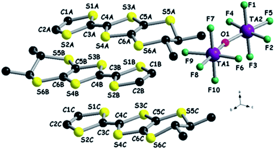
We then turned our attention to a straightforward preparation of (n-Bu4N)2Ta2F10O. The oxo-bis[pentafluorotantalate(V)] dianion [Ta2F10O]2− is scarcely mentioned in the literature, yet full credit should be given to the pioneering work of Dewan, Guerchais and coll. who reported the single crystal X-ray structure of (Et4N)2Ta2F10O44 and details on its preparation by the smooth hydrolysis of (Et4N)TaF6 in aqueous methanolic solutions, together with full 19F NMR characterization.41 Later on, only another couple of reports described crystalline compounds containing this ditantalate dianion with aza-crown45 or dihydro-phenanthroline cations,46 where the dianion resulted from the action of HF on Ta2O5. Note that in the latter report the authors erroneously stated that they described the first example of the [Ta2F10O]2− dianion. According to the protocol established by Dewan, Guerchais and coll.,41 smooth hydrolysis of a methanol solution of (n-Bu4N)TaF6 in the presence of a methanolic solution of (n-Bu4N)OH provided a clean sample of (n-Bu4N)2Ta2F10O. Solution 19F NMR measurements of the sample showed only a doublet (32 ppm) and a quintuplet (9 ppm) integrating for 8H and 2H, respectively, with the coupling constant J = 35 Hz (Fig. S4, ESI†).41 Moreover, a molecular peak at m/z = 810 in the negative mode of ESI-MS (electrospray ionization mass spectrometry), corresponding to the [(n-Bu4N)Ta2F10O]− ion, was clearly observed. Finally, single crystal X-ray measurements definitely assessed the structure of (n-Bu4N)2Ta2F10O which crystallizes in the monoclinic system, centrosymmetric space group C2/c, with one independent cation and half of the anion in the asymmetric unit (Fig. 1, Table S1, ESI†). As in the other three structures containing [Ta2F10O]2−, mentioned above, the oxygen atom lies on a symmetry element, i.e. a 2-fold rotation axis in this case. The Ta–O distance is 1.8884(3) Å, the equatorial Ta–Feq bond lengths range between 1.868(4) and 1.893(4) Å, and the axial Ta–F is slightly longer (1.932(3) Å), while the Ta–O–Ta motif is linear (177.5(4)° for the Ta1–O1–Ta1* angle) (Fig. S5, Table S2, ESI†).
 | ||
| Fig. 1 Molecular structure of (n-Bu4N)2Ta2F10O. The carbon atom C16 is disordered over two positions, C16A (0.5) and C16B (0.5). Hydrogen atoms have been omitted. | ||
Furthermore, the experimental powder X-ray diagram of the polycrystalline bulk sample perfectly fits the simulated diagram generated from the single crystal data (Fig. S6, ESI†), thus indicating the purity of the (n-Bu4N)2Ta2F10O salt.
We next attempted the synthesis of (n-Bu4N)Ta2F11 by mixing a clean sample of (n-Bu4N)TaF6 with equimolar amounts of TaF5 in anhydrous CH2Cl2.36 However, as mentioned by Brownstein,36 isolation of (n-Bu4N)Ta2F11 in the solid state failed. Variation of the preparation protocol by using solid state ball mill mixing of the reagents or microwave activation did not provide different results. With the solid obtained from (n-Bu4N)TaF6 and TaF5 after evaporation of CH2Cl2 we performed electrocrystallization experiments with TMTSF, yet the only crystalline material that we harvested was the classical Bechgaard phase (TMTSF)2TaF6. In conclusion, our results of this fluorotantalate anion saga clearly point out that TaF6− tends to hydrolyse and condense to give the very stable [Ta2F10O]2− dianion, with a geometry very similar to the elusive [Ta2F11]− monoanion, whose isolation in the solid state requires, as mentioned in the Introduction, very anhydrous anaerobic conditions. These unambiguous experimental facts cast doubts upon the correct assignment of the anion in the earlier results concerning the (TMTSF)3Ta2F1133 and (BEDT-TTF)3Ta2F1134,35 radical cation salts. Furthermore, in their study describing the preparation and properties of the Fabre phase (TMTTF)2TaF6, Nakamura et al. briefly mentioned the formation of an unexpected crystalline by-product formulated as (TMTTF)3Ta2F10O,15 without providing any further details on its structure or properties. We have therefore addressed for the first time the electrocrystallization of TMTSF, TMTTF and BEDT-TTF in the presence of the new salt (n-Bu4N)2Ta2F10O with the objective of shedding light on the real nature of the anion, i.e. [Ta2F10O]2−versus [Ta2F11]−, in the corresponding radical cation salts with respect to the earlier reports.15,33–35 Subsequently, we investigated the chiral donor DM-EDT-TTF, as a representative of a non-centrosymmetric TTF donor, in combination with the same dianion [Ta2F10O]2−.
2.2 Radical cation salts
Electrocrystallization of TMTTF and TMTSF in the presence of (n-Bu4N)2Ta2F10O in CH2Cl2 at 20 °C provided black crystalline plates on a platinum electrode. Single crystal X-ray diffraction analyses show that the two compounds are isostructural and formulated as (TMTTF)3Ta2F10O and (TMTSF)3Ta2F10O, respectively, in agreement with the 3:1 stoichiometry for the unexpected poly-type salt mentioned in the report by Nakamura et al.15 Moreover, the crystal parameters and packing of the donors are identical to those described for the (TMTSF)3Ta2F11 salt,33 suggesting that the real anion in this case was [Ta2F10O]2− and not [Ta2F11]−. This makes, of course, a big difference in the understanding of the electron transport properties of this salt correlated with the band structure calculations, since the band filling completely changes (vide infra). The salts crystallize in the triclinic system, P space group, with one and a half independent donors and half anion in the asymmetric unit, with the oxygen atom of the anion situated on an inversion centre, thus giving a 3:1 stoichiometry. The centrosymmetric donors, i.e. S5–S6 and Se5–Se6, are sandwiched between two equivalent non-centrosymmetric donors S1–S4 and Se1–Se4, respectively, providing a trimeric unit (Fig. 2).
 | ||
| Fig. 2 Molecular structures of (TMTTF)3Ta2F10O (left) and (TMTSF)3Ta2F10O (right) with a focus on the trimeric unit of donors and the centrosymmetric anion. | ||
Within the trimers, the centrosymmetric donors Ch5–Ch6 (Ch = chalcogen) possess longer central C![[double bond, length as m-dash]](https://www.rsc.org/images/entities/char_e001.gif) C bond lengths than the non-centrosymmetric ones Ch1–Ch4 (Table S3†), suggesting a higher oxidation degree for the former. With an oxidation degree of +2 for three donors, we can hypothesize that Ch5–Ch6 bear the oxidation state +1, while Ch1–Ch4 are in the mixed valence oxidation state +0.5 (vide infra the band structure calculations).
C bond lengths than the non-centrosymmetric ones Ch1–Ch4 (Table S3†), suggesting a higher oxidation degree for the former. With an oxidation degree of +2 for three donors, we can hypothesize that Ch5–Ch6 bear the oxidation state +1, while Ch1–Ch4 are in the mixed valence oxidation state +0.5 (vide infra the band structure calculations).
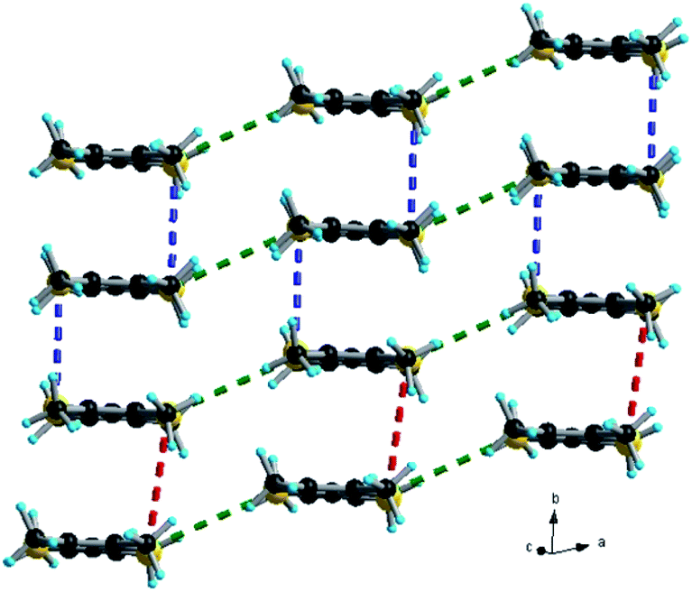
The trimeric units form stacks, along the b direction, interacting laterally along a, thus providing organic layers separated by anions, as classically observed in many TTF based radical cation salts with organic–inorganic segregation in the solid state (see Fig. 3 for (TMTSF)3Ta2F10O and Fig. S7, ESI,† for (TMTTF)3Ta2F10O). The intermolecular intra-trimer Ch⋯Ch distances are much shorter on average than the inter-trimer ones.
 | ||
| Fig. 3 Packing diagram of (TMTSF)3Ta2F10O in the ab plane with an emphasis on the Se⋯Se short contacts: red dotted lines, 4.12 Å; blue dotted lines, 3.73 Å; green dotted lines, 3.95–3.99 Å. | ||
Accordingly, in (TMTSF)3Ta2F10O the intra-trimer short Se⋯Se intermolecular contacts are in the range of 3.73–3.83 Å, while the inter-trimer ones are 4.12–4.20 Å (Fig. 3). In the TMTTF counterpart the corresponding S⋯S contacts measure 3.55–3.63 Å and 4.21 Å, respectively (Fig. S7†). Interestingly, all the fluorine atoms of the anion engage in intermolecular hydrogen bonding with the hydrogen atoms of the donor methyl groups, thus providing a certain rigidity to the assembly, with an interconnection along c between the organic layers (see Fig. 4 for (TMTSF)3Ta2F10O and Fig. S8–S9† for (TMTTF)3Ta2F10O, Tables S4 and S5, ESI†) through these hydrogen bond interactions.
 | ||
| Fig. 4 CH⋯F short contacts in the structure of (TMTSF)3Ta2F10O in the bc (left) and ac (right) planes. Red dotted lines: 2.47–2.54–2.56 Å, blue dotted lines: 2.72–2.75–2.77–2.81 Å and green dotted lines: 2.82–2.86 Å. | ||
Note that the centrosymmetric donors S5–S6 and Se5–Se6, bearing the oxidation state +1, establish hydrogen bonding with fluorine atoms from both [TaF5] fragments of the anion, since they are located at the same level as the bridging oxygen atom (see also Fig. 2).
Following the preparation of these first materials, the attempts of electrocrystallization of BEDT-TTF in the presence of (n-Bu4N)2Ta2F10O in CH2Cl2 at 20 °C afforded crystals as black shiny plates on a Pt electrode. Curiously again, the crystalline parameters of the as-prepared single crystals of (BEDT-TTF)3Ta2F10O correspond to those of the (BEDT-TTF)3Ta2F11 phase described more than 30 years ago,34,35 with the donor packing and their arrangement with respect to the anions being the same (vide infra). Unfortunately, we could not find any experimental details on the preparation of the (BEDT-TTF)3Ta2F11 salt whose crystal structure was reported as being pseudo-orthorhombic, with a β angle of 90.230°.34 In our hands, the compound (BEDT-TTF)3Ta2F10O crystallized in the monoclinic space group P21/a, with the β angle having a value of 90.234(9)° (Table S1†). In the asymmetric unit there are one and a half donors and half of anion, with the central CC bond of the donor S9–S10 and the oxygen atom located on inversion centres (Fig. 5).
 | ||
| Fig. 5 Molecular structure of (BEDT-TTF)3Ta2F10O. | ||
Note the statistical disorder 0.68:0.32 of one of the ethylene bridges of the non-centrosymmetric donor S1–S4. Compared to the previous two salts presenting the same 3:1 stoichiometry, i.e. (TMTSF)3Ta2F10O and (TMTTF)3Ta2F10O, the anions are rotated now by 90° with respect to the donors, which stack along the a direction by the formation of trimeric units. Within the trimers the donors are practically eclipsed, while from one trimer to the other there is a strong longitudinal shift. The shortest intra-stack intermolecular S⋯S distances are again those of intra-trimers (3.58–3.68 Å), while those between trimers in the same stack are much longer, i.e. 4.10–4.16 Å. Furthermore, several short lateral S⋯S distances (3.61–3.69 Å) are observed between donors from parallel stacks in the ab plane (Fig. 6).
 | ||
| Fig. 6 Packing diagram of (BEDT-TTF)3Ta2F10O with an emphasis on the S⋯S short contacts: red dotted lines, 4.10 Å; blue dotted lines, 3.58 Å; green dotted lines, 3.61–3.66–3.69 Å. Hydrogen atoms are omitted for clarity. | ||
In line with the two previous salts, the central CC and C–S bond length values (Table S6†) indicate that the centrosymmetric donor S9–S10 (see Fig. 5) is fully oxidized to the radical cation state +1, while the non-centrosymmetric one is in the mixed valence state +0.5. Again, all the fluorine atoms engage in intermolecular hydrogen bonding with hydrogen atoms of the ethylene groups (Fig. S10–S11, Table S7, ESI†). As a general feature in all the radical cation salts discussed so far, and also in the precursor (n-Bu4N)2Ta2F10O, the Ta–O–Ta angle is 180° and the Ta–O and Ta–F bond lengths have, respectively, comparable values (Table S2†).
The three materials described so far involve centrosymmetric donors in combination with the centrosymmetric dianion [Ta2F10O]2−, a feature which was expressed in the crystal structures of the three compounds of 3:1 stoichiometry since one of the donors and the anion crystallized on inversion centres. As mentioned already, the fact that TMTTF and TMTSF provide isostructural radical cation salts with the same anion is not unexpected, while the formation of a salt with BEDT-TTF presenting many common structural features with the former two is unprecedented. The similar behaviour of the three donors, affording 3:1 salts with the formation of trimeric units with the same charge distribution, is very likely triggered by the peculiar shape of the anion, its charge and the establishment of intermolecular hydrogen bonding. In order to disclose the role of the symmetry of the donor in the occurrence of 3:1 phases with the new dianion, we decided to use the racemic and enantiopure (S,S) forms of DM-EDT-TTF (Scheme 1) as representatives of non-centrosymmetric donors. Note that the use of (S,S)-DM-EDT-TTF would necessarily result in a salt crystallizing in a non-centrosymmetric space group, thus preventing the anion to be located on an inversion centre as observed in the previous salts.
Electrocrystallization of both (rac)- and (S,S)-DM-EDT-TTF in the presence of (n-Bu4N)2Ta2F10O in CHCl3 at 20 °C afforded black crystalline needles of [(rac)-DM-EDT-TTF]3Ta2F10O and [(S,S)-DM-EDT-TTF]3Ta2F10O, that is two isostructural radical cation salts with, again, 3:1 stoichiometry. The former crystallized in the monoclinic system, centrosymmetric space group P21/c, while the latter in the orthorhombic system, non-centrosymmetric space group P212121, in both cases with three donors and one anion in general positions in the asymmetric unit (see Fig. 7 for (S,S) and Fig. S12, ESI,† for (rac)).
 | ||
| Fig. 7 Molecular structure of [(S,S)-DM-EDT-TTF]3Ta2F10O together with a partial atom numbering scheme. Hydrogen atoms have been omitted for clarity. | ||
These two salts represent the first examples of crystalline compounds where the [Ta2F10O]2− dianion does not sit on a symmetry element, i.e. an inversion centre or rotation axis, a feature very likely triggered by the non-centrosymmetry of the donor. Interestingly, the anion is not linear anymore but slightly bent, with Ta1–O1–Ta2 angles of 161.1(8)° and 156.7(6)° for the (rac) and (S,S) forms, respectively (Table S8†). In both salts the donors form similar parallel stacks, reminiscent of a β-phase structural arrangement, along a for (S,S) and along b for (rac), with an alternation of the three donors within the same stack and shorter intermolecular S⋯S distances within the trimeric unit, i.e. 3.53–3.55 Å for (S,S), than those between the trimers (3.74–3.81 Å), at the limit of the sum of the van der Waals radii (see Fig. 8 for (S,S) and Fig. S13–S14, ESI,† for (rac)). The interstack S⋯S distances range between 3.64 and 4.04 Å for (S,S), while the corresponding distances for (rac) have comparable values. The methyl substituents occupy equatorial positions as observed in most of the radical cation salts of DM-EDT-TTF,28,29,31 while for the neutral precursor, the bis(axial) conformer, found to be more stable in the gas phase,47 was characterized even in the solid state.29 For the racemic salt a 0.5:0.5 statistical occupational disorder of the ethylene bridges is observed for all three independent donors thus leading to the co-existence of both enantiomers on the same crystallographic positions, as already encountered in radical cation salts of racemic tetramethylated BEDT-TTF (TM-BEDT-TTF).48,49
 | ||
| Fig. 8 Packing diagram of [(S,S)-DM-EDT-TTF]3Ta2F10O with an emphasis on the S⋯S short contacts along a: red dotted lines, 3.74–3.81 Å; blue dotted lines, 3.53–3.55 Å (top). Packing diagram of [(S,S)-DM-EDT-TTF]3Ta2F10O with an emphasis on the S⋯S short contacts in the ab plane: red dotted lines, 3.74 Å; blue dotted lines, 3.53–3.55 Å; green dotted lines, 3.76 Å; violet dotted lines, 3.64–3.67–3.68 Å; light blue dotted lines, 4.04 Å (bottom). Hydrogen atoms are omitted for clarity. | ||
The orientation of the anion with respect to the donors resembles the one observed in the (BEDT-TTF)3Ta2F10O salt, that is with the Ta1–O–Ta2 axis perpendicular to the donor stacks. Again, a complex set of hydrogen bonding is established between vinylic, methyl and methine hydrogen atoms and fluorine atoms (see Fig. S15 and Table S9 for (rac), Fig. S16–S17 and Table S10 for (S,S), ESI†), thus illustrating the paramount role of the anion in the occurrence of this robust series of 3:1 salts.
As in the previous compounds with TMTTF, TMTSF and BEDT-TTF, the +2 charge is unevenly distributed over the three donors, according to the analysis of the central CC and C–S bond lengths (Table S11†), yet the difference is less marked for the enantiopure salt than for the racemic one.
2.3 Single crystal conductivity measurements
The structural analysis of the five radical cations salts, showing the same 3:1 stoichiometry and existence of alternating trimeric units within parallel stacks resulting in β-type packing, could suggest comparable electron transport behaviour of these materials. We then proceeded to temperature dependent single crystal resistivity measurements for all the materials. A first interesting comparison can be made between (TMTSF)3Ta2F10O and (TMTTF)3Ta2F10O which present exactly the same packing and orientation of the anion with respect to the stack direction. Both compounds are semiconductors, with room temperature conductivities σRT of 0.25 S cm−1 and 2.5 × 10⁻³ S cm−1, and activation energies Ea of 500 K and 1250 K for the TMTSF and TMTTF salts, respectively (see Fig. 9, S18, ESI, for TMTSF and Fig. S19† for TMTTF). The former material is thus two orders of magnitude more conductive than the latter, a difference which is in agreement with the different band gap energy value (vide infra).
 | ||
| Fig. 9 Temperature dependence of the electrical resistivity plotted as logρ versus T, for a single crystal of (TMTSF)3Ta2F10O (top) and for a single crystal of (BEDT-TTF)3Ta2F10O (bottom). The red line is the linear fit giving the activation energy from the law ρ = ρ0exp(Ea/T) determined in the temperature range 160–300 K (top) and 135–300 K (bottom). The small jumps on the resistivity curve of (TMTSF)3Ta2F10O are due to microcracks in the crystal occurring during the cooling down. | ||
The conducting behaviour of (BEDT-TTF)3Ta2F10O resembles that of (TMTSF)3Ta2F10O, with a room temperature conductivity value σRT of 0.3 S cm−1 and an activation energy Ea of 800 K (Fig. 9 and S20, ESI†). However, the resistivity increases slightly faster than the activation law below ∼130 K, which could be the sign of a phase transition towards a more insulating state. Note that in the previous articles concerning (TMTSF)3Ta2F11 and (BEDT-TTF)3Ta2F11, both of them were mentioned as having metallic behaviour. However, we could not find any temperature dependent resistivity study for the latter but only EPR investigations.34,35
Not surprisingly, when considering the similar structural features of the three previous materials, the two salts based on the non-symmetric donor DM-EDT-TTF show semiconducting behaviour as well. Interestingly, the enantiopure salt is at least three times more conducting than the racemic form. Indeed, a room temperature conductivity value σRT of 0.1–0.3 S cm−1 (Ea = 1300 K) was determined for [(rac)-DM-EDT-TTF]3Ta2F10O, while values of σRT = 1.1 S cm−1 and Ea = 1050 K have been found for the (S,S) enantiopure salt (Fig. 10 and S21, ESI†). Note, however, that the racemic compound has been measured in two points because of the small size of the crystals, and this can slightly underestimate the conductivity.
 | ||
| Fig. 10 Temperature dependence of the electrical resistivity plotted as logρ versus T, for a single crystal of [(rac)-DM-EDT-TTF]3Ta2F10O (top) and for a single crystal of [(S,S)-DM-EDT-TTF]3Ta2F10O (bottom). The red line is the linear fit giving the activation energy from the law ρ = ρ0exp(Ea/T) determined in the temperature range of 165–290 K (top) and 200–290 K (bottom). The small jumps on the resistivity curve of the (S,S) enantiopure salt are due to microcracks in the crystal occurring during the cooling down. | ||
2.4 Band structure calculations
In order to correlate the solid state structures, electron transport properties and electronic states of our materials, we proceeded to extended Hückel type tight-binding band structure calculations. For comparison sake, the TMTXF (X = T, S) salts will be discussed first, followed by the DM-EDT-TTF salts, and then by the BEDT-TTF salt. | ||
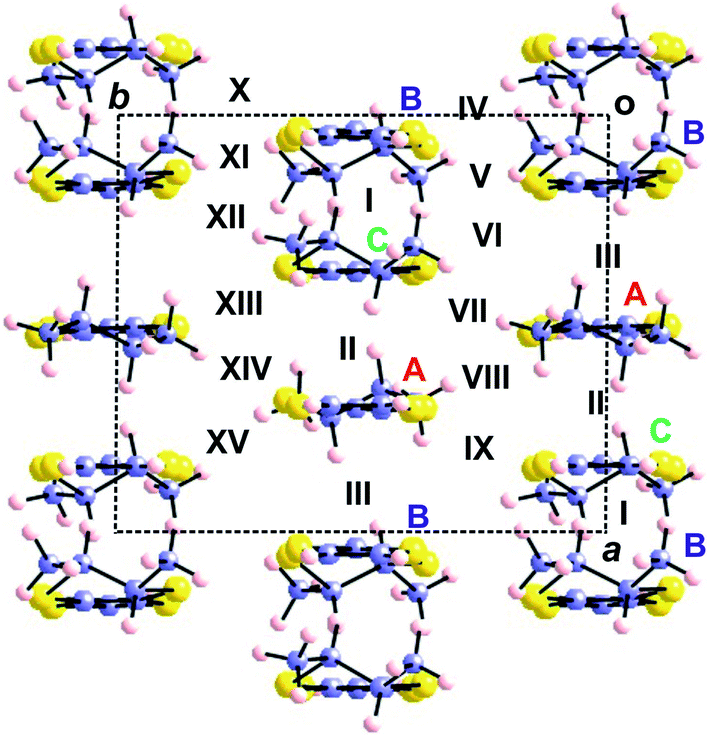
| Fig. 11 Donor layer of the (TMTXF)3Ta2F10O (X = T, S) salts where the different donors and intermolecular interactions are labelled. | ||
| Interaction (type) | (TMTSF)3Ta2F10O | (TMTTF)3Ta2F10O |
|---|---|---|
| I (A–B) | 0.7561 | 0.7368 |
| II (A–A) | 0.3458 | 0.0105 |
| III (A–A) | 0.0261 | 0.0360 |
| IV (B–B) | 0.0349 | 0.0295 |
| V (A–A) | 0.0696 | 0.1302 |
| VI (A–B) | 0.0118 | 0.0205 |
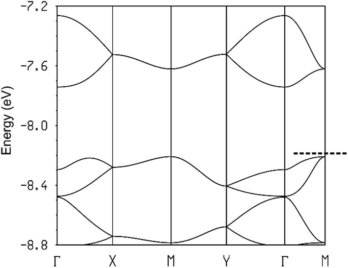
The calculated band structures near the Fermi level for the two salts are shown in Fig. 12. As expected, the three bands are mostly built from the three TMTXF HOMOs. Because Ta2F10O is a dianion and the stoichiometry is 3:1, the three HOMO bands of Fig. 12 must contain two holes. Since the upper band is in both cases separated from the next band by a clear band gap, the upper band is empty and the two salts are band gap semiconductors. The minimum of the upper band of the (TMTSF)3Ta2F10O salt (Fig. 12a) exhibits almost the same dispersion along the (a* + b*) and (−a* + b*) directions (i.e. the M → Γ and S → Γ directions in Fig. 12, respectively) so that the conductivity associated with the electron carriers will be quite isotropic within the (a,b)-plane. In contrast, the middle band in Fig. 12a exhibits a considerably larger dispersion along b* so that the upper part of this band has a small effective mass along this direction; the conductivity associated with the hole carriers will be quite anisotropic with better conductivity around the chain direction. We conclude that (TMTSF)3Ta2F10O is an anisotropic two-dimensional (2D) semiconductor with better conductivity along the TMTSF chains. In contrast, the two upper bands of (TMTTF)3Ta2F10O exhibit only a modest dispersion along all directions and the band gap is larger (Fig. 12b). Both factors should make the TMTTF salt considerably less conductive (and less anisotropic) than the TMTSF one, as confirmed by the resistivity measurements. The calculated band gap for the TMTSF salt is only 40% that of the TMTTF salt, which is in good agreement with the ratio between the experimental activation energies.
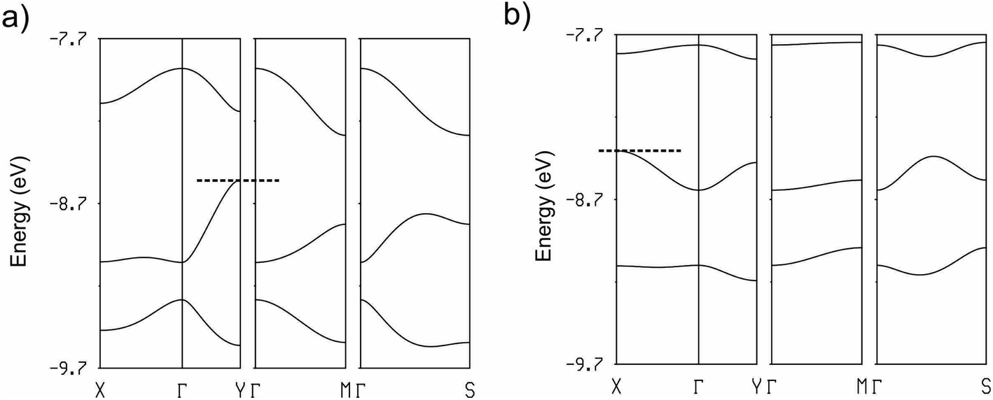 | ||
| Fig. 12 Calculated band structure for the donor layers of (TMTSF)3Ta2F10O (a) and (TMTTF)3Ta2F10O (b) where the dashed line refers to the highest occupied level and Γ = (0, 0), X = (a*/2, 0), Y = (0, b*/2), M = (a*/2, b*/2) and S = (−a*/2, b*/2). | ||
For symmetry reasons, when three TMTXF HOMOs interact to generate the levels of a linear trimer like those in the present salts, they lead to a middle level (Ψ2) which is entirely made of the HOMOs of the outer donors (Fig. 13). As a consequence of the orthonormality of the three orbitals, the upper level (Ψ3) contains contributions of the three HOMOs but it is more strongly based on the central one (i.e. in the case of the present salts, donor B). As a result, since the upper, empty band of the two salts is based on the Ψ3 level, the central donor of the trimer must bear a more positive charge and thus a longer central CC bond length, in agreement with our structural data, that is 1.364(10) Å (donor A) vs. 1.382(13) Å (donor B) in the TMTTF salt and 1.356(6) Å (donor A) vs. 1.371(8) Å (donor B) in the TMTSF salt. Note that the strength of the interaction between the A–B–A trimers along the chain direction, which is proportional to interaction II, is the most noticeable difference between the two salts. The donor…donor interaction II in the TMTSF salt is a typical ring-over-bond one.51 However, in the TMTTF salt, because of the interaction with the anions, the two donors exhibit a non-negligible rotation along the chain axis as well as a small bending of the molecular plane. Both factors decrease considerably interaction II in the TMTTF salt which in fact is almost nil, whereas it is substantial in the TMTSF one (see Table 1). This feature is especially important when considering the dispersion of the middle band which is concentrated on the outer A donors of the trimers and leads to the hole carriers. Ultimately, this feature is mostly the origin of the anisotropic behaviour of the TMTSF salt with better conductivity along the chain direction as well as of the considerably lower conductivity of the TMTTF salt. We thus conclude that an apparently minor variation in the donor⋯anion interactions is the origin of the difference in the transport properties of these two isostructural salts.52
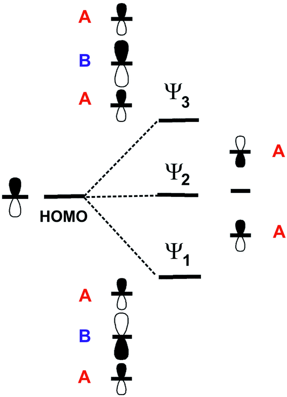 | ||
| Fig. 13 Schematic representation of the three levels of a linear trimer generated from three TMTXF HOMOs. For simplicity every TMTXF HOMO is represented as a simple p orbital. | ||
 | ||
| Fig. 14 Donor layer of the (rac)- and (S,S)-(DM-EDT-TTF)3Ta2F10O salts where the different donors and intermolecular interactions are labelled. The donor chains run along b for the (rac)- salt but along a for the (S,S)- salt. | ||
| Interaction (type) | (S,S)- | (rac)- |
|---|---|---|
| I (B–C) | 0.8698 | 0.9422 |
| II (A–C) | 0.6637 | 0.7115 |
| III (A–B) | 0.4913 | 0.4450 |
| IV (B–C) | 0.0740 | 0.0796 |
| V (B–B) | 0.0198 | 0.0257 |
| VI (B–C) | 0.0702 | 0.0796 (=IV) |
| VII (A–C) | 0.0051 | 0.0139 |
| VIII (A–A) | 0.0440 | 0.0479 |
| IX (A–C) | 0.0193 | 0.0139 (=VII) |
| X (B–C) | 0.0702 (=VI) | 0.0797 |
| XI (B–B) | 0.0198 (=V) | 0.0254 |
| XII (B–C) | 0.0740 (=IV) | 0.0797 (=X) |
| XIII (A–C) | 0.0193 (=IX) | 0.0212 |
| XIV (A–A) | 0.0440 (=VIII) | 0.0499 |
| XV (A–C) | 0.0051 (=VII) | 0.0212 (=XIII) |
The calculated band structure for [(S,S)-DM-EDT-TTF]3Ta2F10O is shown in Fig. 15 (for the (rac)- salt see Fig. S22, ESI†). The band structure shown in Fig. 15 is in fact also quite similar to that of (TMTSF)3Ta2F10O (Fig. 12a) except that in the present case every band is split into two bands because the repeat unit contains two equivalent chains. As for the TMTSF salt (note that the chain direction is b in the TMTSF salt but a in the present salt), the minimum of the conduction band (electron carriers) shows similar values for the energy dispersion along the intra-chain (energy difference between X and Γ in Fig. 15) and inter-chain (the inter-chain energy dispersion in Fig. 15 is given by the energy difference between the two upper bands at X because of the band folding) directions. In contrast the valence band (hole carriers) is clearly 1D along the chain direction (considerably stronger dispersion along the Γ–X and Y–M bands). Thus, despite the different donor and slightly different structural arrangement, the DM-EDT-TTF and TMTSF salts are strongly related and all of these systems should be anisotropic 2D semiconductors with better conductivity along the chain direction.
 | ||
| Fig. 15 Calculated band structure for the donor layers of [(S,S)-DM-EDT-TTF]3Ta2F10O where the dashed line refers to the highest occupied level and Γ = (0, 0), X = (a*/2, 0), Y = (0, b*/2), M = (a*/2, b*/2) and S = (−a*/2, b*/2). | ||
The band structures of the two DM-EDT-TTF salts are very similar but that of the (rac)- salt (Fig. S22, ESI†) exhibits a larger gap (0.43 vs. 0.19 eV), in agreement with the conductivity measurements. The reason can be understood on the basis of the nature of the states associated with the gap. For a triply folded band of an ideal chain built from TTF-based HOMOs, the nature of these states is that schematically depicted in Fig. 16. The band gap separating the upper band from the middle one at the border of the Brillouin zone (X in Fig. 16) will be larger when the intra-cell B⋯C and C⋯A interactions are stronger and the inter-cell A⋯B interaction is weaker. As can be seen in Table 2, interactions I (B–C) and II (A–C) are stronger whereas interaction III (A–B) is weaker for the (rac)- salt which, consequently, must exhibit the largest gap, as found in our conductivity measurements.
 | ||
| Fig. 16 Schematic representation of the band structure of a chain with a repeat unit of three identical DM-EDT-TTF HOMOs. The two crystal orbitals leading to the opening of a gap when the chain is not uniform are shown. For simplicity, every DM-EDT-TTF HOMO is represented as a simple p orbital. | ||
 | ||
| Fig. 17 Donor layer of the (BEDT-TTF)3Ta2F10O salt where the different donors and intermolecular interactions are labelled. | ||
| Interaction (type) | |βHOMO–HOMO| (eV) |
|---|---|
| I (A–A) | 0.2320 |
| II (A–B) | 0.7385 |
| III (A–A) | 0.0403 |
| IV (A–B) | 0.0833 |
| V (A–B) | 0.0897 |
As for all other salts the intra-chain interactions clearly dominate and despite the different intra-chain overlaps the strength of these interactions is comparable to that of the TMTSF and DM-EDT-TTF salts. It is clear that from the electronic viewpoint the basic units of the layers are again A–B–A trimers. The calculated band structure (Fig. 18) shows three clearly discernible pairs of bands corresponding to the three HOMO levels of the trimer. Note, however, that despite this common feature the shape of the bands is different because the inter-trimer interactions are different in the three series of salts. However, the important fact of Fig. 18 is that due to the 3:1 stoichiometry, the HOMO bands must contain four holes so that only the two lower pairs of bands are filled. Consequently there is a band gap separating the empty and filled bands and (BEDT-TTF)3Ta2F10O is a regular semiconductor.
 | ||
| Fig. 18 Calculated band structure for the donor layers of (BEDT-TTF)3Ta2F10O where the dashed line refers to the highest occupied level and Γ = (0, 0), X = (a*/2, 0), Y = (0, b*/2), M = (a*/2, b*/2) and S = (−a*/2, b*/2). | ||
Analysis of the crystal orbitals confirms that every pair of bands in Fig. 18 corresponds to the standard description of the levels of a trimer (i.e. those shown in Fig. 13). For instance, the pair in the middle is almost exclusively built from A type donors and the upper pair is ∼2/3 on donor B and ∼1/3 on donor A. Consequently, since the latter pair is empty it turns out that donor B must hold a more positive charge. This is in agreement with the fact that the central CC distance is longer for donor B (1.392(13) vs. 1.360(8) Å). It may seem surprising that the band dispersion of the upper pair of bands is practically identical along the two main directions of the lattice (see Γ–X, i.e. a, and Γ–Y, i.e. b) whereas the interaction between trimers (i.e. interaction I) is around three times stronger than the inter-chain interactions (interactions III to V). However, two reasons are behind this observation. First, every trimer interacts with another trimer in different chains through several donor…donor interactions but only through one if they are in the same chain. Second, since the effective unit is a trimer and thus the orbital is delocalized among the three donors, orbital normalization imposes that the effective inter-trimer interaction along the chains is smaller than interaction I (in fact around three times smaller). Note that the minimum of this upper empty band (occurring at Γ) exhibits larger (and very isotropic) dispersion than the maxima of the upper filled bands (occurring at M and in between Γ and X) so that the electron carriers will dominate the conductivity. We thus conclude that (BEDT-TTF)3Ta2OF10 is an isotropic 2D diamagnetic semiconductor with an indirect band gap.
In summary, although all 3:1 salts discussed share most aspects of the electronic structure and are semiconducting with uneven distribution of the charge, the structural variations induce subtle differences differentiating all compounds. Thus, whereas the TMTSF and (S,S)-DM-EDT-TTF salts are both anisotropic 2D semiconductors with better conductivity along the chains, the band gap is indirect in the former but direct in the latter. The BEDT-TTF salt has an indirect band gap as the TMTSF salt, but in contrast to both the TMTSF and (S,S)-DM-EDT-TTF salts, it is an isotropic 2D semiconductor. Both in the case of the TMTSF/TMTTF and (S,S)-/(rac)-DM-EDT-TTF pairs of salts one of them has a conductivity which is substantially larger because of differences in the interactions along the chains.
3. Conclusions
Following the full characterization of its tetra-n-butyl ammonium salt, we have demonstrated the occurrence of the oxo-bis[pentafluorotantalate(V)] dianion [Ta2F10O]2− in a series of radical cation salts showing the same 3:1 stoichiometry and involving the symmetric classical donors TMTTF, TMTSF and BEDT-TTF and also the non-symmetric racemic and (S,S) enantiopure donor DM-EDT-TTF. In all the salts, formation of trimeric donor units is observed, with an uneven charge distribution between the donors, together with the establishment of numerous intermolecular hydrogen bonding interactions between the fluorine atoms of the anion and the methyl (TMTTF, TMTSF), methylene (BEDT-TTF), and methyl, methine and vinyl (DM-EDT-TTF) protons. The orientation of the Ta–O–Ta long axis of the anion is either parallel (TMTSF, TMTTF) or perpendicular (BEDT-TTF, DM-EDT-TTF) to the donor stacking direction. We hypothesize that the peculiar shape of the anion, i.e. linear or a slightly tilted corner shared double octahedron, and its templating role through the formation of hydrogen bonding trigger the propensity towards the same 3:1 stoichiometry no matter what donor we used. Single crystal resistivity measurements show semiconducting behaviour for all five materials, with room temperature conductivity values between 0.25 and 1.1 S cm−1 except for the TMTTF salt, which is two orders of magnitude less conducting than the TMTSF counterpart. Worth noting is also the three times higher conductivity value for the enantiopure (S,S) salt of DM-EDT-TTF than for the racemic form. These differences accurately correlate with the band gap energy values derived from the tight-binding band structure calculations, which are in agreement with the band gap semiconducting behaviour for all the materials investigated herein. Although the five Ta2F10O salts discussed here have donor layers with a similar general organization, built from chains with a repeat unit of three donors, variations in the inter- and intra-trimer interactions modulate their band structure (energy dispersion and band gaps). The chains in TMTSF and TMTTF salts are built from interacting trimers but the inter-trimer interaction is considerably smaller in the latter leading to a larger band gap and smaller conductivity. The two DM-EDT-TTF salts exhibit stronger inter-trimer interactions and are better considered as chains of donors. In that case a combination of stronger intra-trimer and weaker inter-trimer interactions is associated with a smaller band gap and thus larger conductivity for the (S,S) salt. The BEDT-TTF salt is also better described as a series of interacting trimers and is a diamagnetic semiconductor.
A feature one cannot elude concerns the validity of the description in the earlier reports of the (TMTSF)3Ta2F1133 and (BEDT-TTF)3Ta2F11 salts.34,35 While this question is not very simple to definitely settle, especially in the case of the latter for which no experimental details for its preparation could be found, we would like to resume the facts against the existence of the [Ta2F11]− monoanion in these salts. As we have largely argued, experimental evidence for the existence of the undecafluoro-tantalate anion in the solid state is very scarce, pointing out that it can be observed only under very anhydrous and anaerobic conditions.37,38 Our own experimental investigations are in agreement with Brownstein's report36 concerning the failure of the isolation in the solid state of the (n-Bu4N)Ta2F11 salt which would be, in principle, the ideal precursor to be engaged in electrocrystallization in order to obtain TTF based radical cation salts in a reproducible manner. In contrast, the oxo-bis[pentafluorotantalate(V)] dianion [Ta2F10O]2− forms very smoothly as a (n-Bu4N)Ta2F10O salt by the gentle hydrolysis of (n-Bu4N)TaF6. In our hands, electrocrystallization experiments under the same conditions as those described for the formation of (TMTSF)3Ta2F11,33 or by using (n-Bu4N)TaF6 not stored in an inert atmosphere, afforded in the same electrocrystallization cell a crystal mixture of the Bechgaard phase (TMTSF)2TaF6 and (TMTSF)3Ta2F10O. Moreover, Nakamura et al. mentioned in their report on (TMTTF)2TaF6 the formation of (TMTTF)3Ta2F10O as a secondary phase.15 All these experimental facts, combined with chemical reactivity issues, strongly suggest that the occurrence of the [Ta2F11]− monoanion in these salts is very unlikely. Last but not least, a common sense argument could be evoked as well. Supposing that (TMTSF)3Ta2F11 and (BEDT-TTF)3Ta2F11 salts could have indeed been serendipitously formed, it seems to us highly improbable that they would be, not one, but both of them, isostructural with their [Ta2F10O]2− counterparts described herein. There is no example, to the best of our knowledge, of isostructural TTF based radical cation salts with a mono and a dianion. But once again, by the scientific rigor principle, we cannot rule out definitely the existence of an isostructural (BEDT-TTF)3Ta2F11 salt in the absence of an experimental protocol in the previous corresponding reports,34,35 although the standard electrocrystallization procedures we applied afforded either (BEDT-TTF)3Ta2F10O or a mixture of (BEDT-TTF)3Ta2F10O and (BEDT-TTF)2TaF6, as in the case of TMTSF.
Future work will be dedicated to the use of other TTF and TSF donor molecules with the new [Ta2F10O]2− dianion in order to take advantage of its propensity to provide mixed valence radical cation salts.
4. Experimental
4.1 Materials and methods
Nuclear magnetic resonance spectra were recorded on a Bruker Avance DRX 300 spectrometer operating at 282 MHz for 19F. Chemical shifts are expressed in parts per million (ppm). The following abbreviations are used: s, singlet; d, doublet; m, multiplet. A Bruker Esquire 3000 plus spectrometer was used for electrospray ionization mass spectrometry (ESI-MS). Elemental analysis was performed using a Flash 2000 Fisher Scientific Thermo Electron analyzer.4.2 Electrocrystallization
4.3 X-ray structure determination
Details about data collection and solution refinement are given in Table S1 (ESI†). Data collections were performed on a BRUKER KappaCCD diffractometer, equipped with a graphite monochromator utilizing MoKα radiation (λ = 0.71073 Å) for (n-Bu4N)2Ta2F10O, (TMTTF)3Ta2F10O, (TMTSF)3Ta2F10O and (BEDT-TTF)3Ta2F10O and on a Rigaku Oxford Diffraction SuperNova diffractometer equipped with an Atlas CCD detector and micro-focus Cu-Kα radiation (λ = 1.54184 Å) for [(rac)-DM-EDT-TTF]3Ta2F10O, [(S,S)-DM-EDT-TTF]3Ta2F10O and (n-Bu4N)TaF6. The structures were solved by direct methods and refined on F2 by full matrix least-squares techniques with SHELX programs. All non-H atoms were refined anisotropically. The H atoms were placed at calculated positions and refined using a riding model. For (BEDT-TTF)3Ta2F10O and [(rac)-DM-EDT-TTF]3Ta2F10O a statistical disorder was applied to lead to various occupation rates: for the former, one ethylene part with 0.68/0.32 occupancy factors, and for the latter, all three ethylene parts with almost 0.5 occupancy factor each. The compound (n-Bu4N)TaF6 has been treated as a twinned structure.4.4 Conductivity measurements
Electrical resistivity was measured in four points on platelet-shaped single crystals 0.5–0.8 mm long for (TMTSF) 3Ta2OF10, (TMTTF)3Ta2OF10 and (rac)-(DM-EDT-TTF)3Ta2OF10. Gold wires were glued with silver paste on aligned gold evaporated contacts. For the platelets of (BEDT-TTF)3Ta2OF10 (0.3–0.4 mm long), it was not possible to evaporate gold contacts on so small samples. Therefore, the four electrical contacts used to measure the in-plane resistivity were point contacts made by silver paste. Because of the small size of the [(rac)-DM-EDT-TTF]3Ta2F10O crystals (maximum length of 0.25 mm), their resistance was measured in two points with gold wires directly attached on both ends of the crystals. Different techniques were used to measure resistivity, either applying a low frequency (≈100 Hz) AC current (1–10 μA) with lock-in amplifier detection or a DC current (1–0.1 μA). We have checked for each crystal that both techniques give the same resistance value at room temperature. Low temperature was provided either by a homemade cryostat equipped with a 4 K pulse-tube or using a Quantum Design Physical Property Measurement System (PPMS).4.5 Band structure calculations
The tight-binding band structure calculations were of the extended Hückel type.53 A modified Wolfsberg–Helmholtz formula was used to calculate the non-diagonal Hμν values.54 All valence electrons were taken into account in the calculations and the basis set consisted of Slater-type orbitals of double-ζ quality for C 2s and 2p, S 3s and 3p, Se 4s and 4p and of single-ζ quality for H. The ionization potentials, contraction coefficients and exponents were taken from previous work.55Conflicts of interest
There are no conflicts to declare.Acknowledgements
This work was supported in France by the National Agency for Research (ANR, Project 15-CE29-0006-01 ChiraMolCo), the CNRS and the University of Angers. Work at Bellaterra (Spain) was supported by the Spanish MICIU through Grant PGC2018-096955-B-C44 and the MINECO through the Severo Ochoa Centers of Excellence Program under Grant SEV-2015-0496 as well as by Generalitat de Catalunya (2017SGR1506).Notes and references
- D. Jérome and H. J. Schulz, Adv. Phys., 1982, 31, 299–490 CrossRef.
- T. Ishiguro, K. Yamaji and G. Saito, Organic Superconductors, Springer-Verlag, Heidelberg, 1998 Search PubMed.
- K. Bechgaard, C. S. Jacobsen, K. Mortensen, H. J. Pedersen and N. Thorup, Solid State Commun., 1980, 33, 1119–1125 CrossRef CAS.
- C. Bourbonnais and D. Jérome, Science, 1998, 281, 1155–1156 CrossRef.
- J.-P. Pouget, Crystals, 2012, 2, 466–520 CrossRef CAS.
- H. Wilhelm, D. Jaccard, R. Duprat, C. Bourbonnais, D. Jérome, J. Moser, C. Carcel and J. M. Fabre, Eur. Phys. J. B, 2001, 21, 175–183 CrossRef CAS.
- K. Bechgaard, K. Carneiro, F. B. Rasmussen, M. Olsen, G. Rindorf, C. S. Jacobsen, H. J. Pedersen and J. C. Scott, J. Am. Chem. Soc., 1981, 103, 2440–2442 CrossRef CAS.
- S. S. P. Parkin, M. Ribault, D. Jérome and K. Bechgaard, J. Phys. C: Solid State Phys., 1981, 14, 5305–5326 CrossRef CAS.
- M. Dressel, M. Dumm, T. Knoblauch and M. Masino, Crystals, 2012, 2, 528–578 CrossRef CAS.
- T. Adachi, E. Ojima, K. Kato, H. Kobayashi, T. Miyazaki, M. Tokumoto and A. Kobayashi, J. Am. Chem. Soc., 2000, 122, 3238–3239 CrossRef CAS.
- M. Itoi, M. Kano, N. Kurita, M. Hedo, Y. Uwatoko and T. Nakamura, J. Phys. Soc. Jpn., 2007, 76, 053703 CrossRef.
- M. Itoi, C. Araki, M. Hedo, Y. Uwatoko and T. Nakamura, J. Phys. Soc. Jpn., 2008, 77, 023701 CrossRef.
- J. M. Williams, M. A. Beno, J. C. Sullivan, L. M. Banovetz, J. M. Braam, G. S. Blackman, C. D. Carlson, D. L. Greer, D. M. Loesing and K. Carneiro, Phys. Rev. B: Condens. Matter Mater. Phys., 1983, 28, 2873–2876 CrossRef CAS.
- A. Maaroufi, C. Coulon, S. Flandrois, P. Delhaes, K. Mortensen and K. Bechgaard, Solid State Commun., 1983, 48, 555–559 CrossRef CAS.
- F. Iwase, K. Sugiura, K. Furukawa and T. Nakamura, J. Phys. Soc. Jpn., 2009, 78, 104717 CrossRef.
- N. Thorup, G. Rindorf, H. Soling, I. Johannsen, K. Mortensen and K. Bechgaard, J. Phys., Colloq., 1983, 44, 1017–1020 CrossRef.
- K. Miyagawa, K. Kanoda and A. Kawamoto, Chem. Rev., 2004, 104, 5635–5653 CrossRef CAS PubMed.
- T. Mori, Chem. Rev., 2004, 104, 4947–4969 CrossRef CAS PubMed.
- H. Kobayashi, R. Kato, T. Mori, A. Kobayashi, Y. Sasaki, G. Saito and H. Inokuchi, Chem. Lett., 1983, 12, 759–762 CrossRef.
- H. Kobayashi, T. Mori, R. Kato, A. Kobayashi, Y. Sasaki, G. Saito and H. Inokuchi, Chem. Lett., 1983, 12, 581–584 CrossRef.
- P. C. W. Leung, M. A. Beno, G. S. Blackman, B. R. Coughlin, C. A. Miderski, W. Joss, G. W. Crabtree and J. M. Williams, Acta Crystallogr., Sect. C: Cryst. Struct. Commun., 1984, 40, 1331–1334 CrossRef.
- Y. Nogami and T. Mori, J. Phys. IV, 2002, 12, 233–234 Search PubMed.
- R. Laversanne, J. Amiell, P. Delhaes, D. Chasseau and C. Hauw, Solid State Commun., 1984, 52, 177–181 CrossRef CAS.
- T. Kawamoto, K. Kurata, T. Mori and R. Kumai, Magnetochemistry, 2017, 3, 14 CrossRef.
- T. Kawamoto, K. Kurata and T. Mori, J. Phys. Soc. Jpn., 2018, 87, 083703 CrossRef.
- N. Avarvari and J. D. Wallis, J. Mater. Chem., 2009, 19, 4061–4076 RSC.
- F. Pop, N. Zigon and N. Avarvari, Chem. Rev., 2019, 119, 8435–8478 CrossRef CAS PubMed.
- F. Pop, P. Auban-Senzier, E. Canadell, G. L. J. A. Rikken and N. Avarvari, Nat. Commun., 2014, 5, 3757 CrossRef PubMed.
- F. Pop, P. Auban-Senzier, A. Frąckowiak, K. Ptaszyński, I. Olejniczak, J. D. Wallis, E. Canadell and N. Avarvari, J. Am. Chem. Soc., 2013, 135, 17176–17186 CrossRef CAS PubMed.
- I. Olejniczak, A. Frąckowiak, K. Ptaszyński, F. Pop and N. Avarvari, J. Phys. Chem. C, 2017, 121, 21975–21984 CrossRef CAS.
- F. Pop, P. Auban-Senzier, E. Canadell and N. Avarvari, Chem. Commun., 2016, 52, 12438–12441 RSC.
- N. Mroweh, P. Auban-Senzier, N. Vanthuyne, E. Canadell and N. Avarvari, J. Mater. Chem. C, 2019, 7, 12664–12673 RSC.
- C. Lenoir, K. Boubekeur, P. Batail, E. Canadell, P. Auban, O. Traetteberg and D. Jérome, Synth. Met., 1991, 41–43, 1939–1942 CrossRef.
- J. V. Acrivos, H. P. Hughes and S. S. P. Parkin, J. Chem. Phys., 1987, 86, 1780–1788 CrossRef CAS.
- J. V. Acrivos, Mol. Cryst. Liq. Cryst., 1996, 284, 411–417 CrossRef CAS.
- S. Brownstein, Inorg. Chem., 1973, 12, 584–589 CrossRef CAS.
- F. Marchetti, G. Pampaloni, C. Pinzino and S. Zacchini, Eur. J. Inorg. Chem., 2013, 5755–5761 CrossRef CAS.
- G. Tavčar and E. Goreshnik, J. Fluorine Chem., 2016, 189, 33–38 CrossRef.
- J. M. Braam, C. D. Carlson, D. A. Stephens, A. E. Rehan, S. J. Compton and J. M. Williams, Inorg. Synth., 1986, 24, 130–143 Search PubMed.
- F. Marchetti, G. Pampaloni and S. Zacchini, J. Fluorine Chem., 2010, 131, 21–28 CrossRef CAS.
- J. Sala-Pala, J. Y. Calves, J. E. Guerchais, S. Brownstein, J. C. Dewan and A. J. Edwards, Can. J. Chem., 1978, 56, 1545–1548 CrossRef CAS.
- A. A. Udovenko, R. L. Davidovich, V. B. Logvinova and V. V. Tkachev, J. Struct. Chem., 2016, 57, 1584–1587 CrossRef CAS.
- M. A. McLoughlin, N. L. Keder and W. C. Kaska, Acta Crystallogr., Sect. C: Cryst. Struct. Commun., 1992, 48, 1098–1099 CrossRef.
- J. C. Dewan, A. J. Edwards, J. Y. Calves and J. E. Guerchais, J. Chem. Soc., Dalton Trans., 1977, 978–980 RSC.
- M. S. Fonari, V. C. Kravtsov, Y. A. Simonov, S. S. Basok, E. V. Ganin, V. O. Gelmboldt, K. Suwinska, J. Lipkowski, O. A. Alekseeva and N. G. Furmanova, Polyhedron, 2008, 27, 2049–2058 CrossRef CAS.
- Z.-H. Meng, Y.-Q. Feng and X.-F. Chen, Acta Crystallogr., Sect. E: Struct. Rep. Online, 2012, 68, m561 CrossRef CAS PubMed.
- T. Cauchy, F. Pop, J. Cuny and N. Avarvari, Chimia, 2018, 72, 389–393 CrossRef CAS PubMed.
- F. Pop, S. Laroussi, T. Cauchy, C. J. Gómez-García, J. D. Wallis and N. Avarvari, Chirality, 2013, 25, 466–474 CrossRef CAS PubMed.
- S. Yang, F. Pop, C. Melan, A. C. Brooks, L. Martin, P. Horton, P. Auban-Senzier, G. L. J. A. Rikken, N. Avarvari and J. D. Wallis, CrystEngComm, 2014, 16, 3906–3916 RSC.
- M.-H. Whangbo, J. M. Williams, P. C. W. Leung, M. A. Beno, T. J. Emge and H. H. Wang, Inorg. Chem., 1985, 24, 3500–3502 CrossRef CAS.
- T. Mori, Bull. Chem. Soc. Jpn., 1998, 71, 2509–2526 CrossRef CAS.
- J.-P. Pouget, P. Alemany and E. Canadell, Mater. Horiz., 2018, 5, 590–640 RSC.
- M.-H. Whangbo and R. Hoffmann, J. Am. Chem. Soc., 1978, 100, 6093–6098 CrossRef CAS.
- J. H. Ammeter, H.-B. Bürgi, J. Thibeault and R. Hoffmann, J. Am. Chem. Soc., 1978, 100, 3686–3692 CrossRef CAS.
- A. Pénicaud, K. Boubekeur, P. Batail, E. Canadell, P. Auban-Senzier and D. Jérome, J. Am. Chem. Soc., 1993, 115, 4101–4112 CrossRef.
Footnote |
| † Electronic supplementary information (ESI) available. CCDC 1999620–1999623, 1999625, 1999626 and 2003148. For ESI and crystallographic data in CIF or other electronic format see DOI: 10.1039/d0sc03665j |
| This journal is © The Royal Society of Chemistry 2020 |