 Open Access Article
Controlling the alignment of 1D nanochannel arrays in oriented metal–organic framework films for host–guest materials design†
Kenji
Okada
 *ab,
Miharu
Nakanishi
a,
Ken
Ikigaki
a,
Yasuaki
Tokudome
 a,
Paolo
Falcaro
 c,
Christian J.
Doonan
 d and
Masahide
Takahashi
 *a
*a
aDepartment of Materials Science, Graduate School of Engineering, Osaka Prefecture University, Sakai, Osaka 599-8531, Japan. E-mail: okada@photomater.com; masa@photomater.com
bJST, PRESTO, 4-1-8 Honcho, Kawaguchi, Saitama 332-0012, Japan
cInstitute of Physical and Theoretical Chemistry, Graz University of Technology, Stremayrgasse 9, Graz 8010, Austria
dDepartment of Chemistry, The University of Adelaide, Adelaide, South Australia 5005, Australia
First published on 14th July 2020
Abstract
Controlling the direction of molecular-scale pores enables the accommodation of guest molecular-scale species with alignment in the desired direction, allowing for the development of high-performance mechanical, thermal, electronic, photonic and biomedical organic devices (host–guest approach). Regularly ordered 1D nanochannels of metal–organic frameworks (MOFs) have been demonstrated as superior hosts for aligning functional molecules and polymers. However, controlling the orientation of MOF films with 1D nanochannels at commercially relevant scales remains a significant challenge. Here, we report the fabrication of macroscopically oriented films of Cu-based pillar-layered MOFs having regularly ordered 1D nanochannels. The direction of 1D nanochannels is controllable by optimizing the crystal growth process; 1D nanochannels align either perpendicular or parallel to substrates, offering molecular-scale pore arrays for a macroscopic alignment of functional guest molecules in the desired direction. Due to the fundamental interest and widespread technological importance of controlling the alignment of functional molecules and polymers in a particular direction, orientation-controllable MOF films will open up the possibility of realising the potential of MOFs in advanced technologies.
Introduction
The ability to precisely align functional small molecules and polymers on macroscopic scales is a key step in the development of high-performance mechanical, thermal, electronic, photonic and biomedical organic devices.1–5 Typically, a uniform external field along one direction, such as mechanical stress, surface rubbing treatment, or electromagnetic radiation, is employed to achieve alignment.6 Although these existing methodologies have realised alignment over large areas, new approaches that use molecular-scale pores to confine guests with a precise spatial orientation are drawing interest as the regularly separated pore walls produce materials that show novel functionality.7–10Metal–organic frameworks (MOFs), also called porous coordination polymers, are crystalline materials synthesized via a node-and-linker approach.11 The pore sizes and chemistry of MOFs can be tuned to enhance host–guest interactions that lead to precise orientation of molecules adsorbed within their pore network. A salient example is the so-called ‘crystalline sponge’ approach that facilitates the structural elucidation of guests by single-crystal X-ray diffraction.12 MOFs composed of 1D pore structures (nanochannels) are excellent candidates for aligning guest molecules; indeed, incorporating molecules within their pore networks has been shown to enhance the mechanical, electrical and optical properties of the frameworks.13–24 Examples of MOFs that possess 1D nanochannels, crystallographically oriented along the c axis, include pillar-layered M2(linker)2DABCO MOFs (linker: 1,4-benzenedicarboxylate (BDC), 1,4-naphthalenedicarboxylate (1,4-NDC), 2,6-naphthalenedicarboxylate (2,6-NDC), and 4,4′-biphenyldicarboxylate (BPDC); DABCO: 1,4-diazabicyclo[2.2.2]octane, M = Cu, Zn) (Fig. 1a). The dimensions of the square shaped pores can be tuned by judicious selection of the organic linker, from 0.57 × 0.57 nm2 (1,4-NDC) to 1.08 × 1.08 nm2 (BPDC),15 facilitating the encapsulation of specific guest molecules and polymers. For instance, Distefano et al. reported that Cu2(BDC)2DABCO partially substituted with 2,5-divinyl-terephthalate could be employed to align vinyl polymers with mechanical and thermal properties, which cannot be achieved by conventional polymer synthesis.21 Furthermore, Smoukov and co-workers showed that aligned conductive polymers can be fabricated within the nanochannels of Zn2(1,4-NDC)2DABCO.16 Though these examples show potential for orienting guests within MOF pores, they were limited to discrete crystallites which typically range in size from nanometres up to millimetres. Liquid-phase epitaxy (LPE) via layer-by-layer (LbL) synthesis, and interfacial growth strategies have been shown to afford orientation-controlled Cu2(linker)2DABCO MOF films.25–32 In the LPE/LbL system, the orientation of the MOF film in a direction normal to the substrate (out-of-plane) can be controlled by using an appropriate self-assembled monolayer (SAM) (conventionally Au-coated substrates are employed).25–30 For the interfacial growth approach, a metal ion-doped polymer substrate is employed as the metal-ion source for the MOF synthesis and the orientation is controlled by the chemical interaction between the framework components and polymer substrate.32 These methodologies require a SAM or a metal ion-doped polymer to control the orientation, which limits the selection of substrate. With these protocols, the fabrication of in-plane oriented MOF film (along the direction parallel to the substrate) over large areas still remains a challenge. Recently, we expanded the scope of this area by developing a novel heteroepitaxial growth method for fabricating MOF films with crystallographic orientation, along all three axes, at the centimetre-scale.33,34 In this case, Cu(OH)2 nanobelts were used as a sacrificial template for the epitaxial growth of 2D Cu2(BDC)2 and 3D Cu2(BDC)2DABCO MOFs.33–37 Metal hydroxides are a versatile sacrificial support for the growth of aligned MOFs as they can be deposited on a variety of substrates such as silicon wafers, SiO2 glasses, and flexible polymeric surfaces. Given that Cu(OH)2 plays two roles as a Cu2+ ion source and a support for MOF growth, the MOF crystal growth process should be examined by considering both the dissolution of the Cu(OH)2 nanobelts and their role in controlling the porous crystal orientation (heteroepitaxy). Detailed investigations of these synthetic conditions, in particular the solution acidity that plays a substantial role in the Cu(OH)2 dissolution, would enable fabrication of MOF films with different orientations (in previous studies,33,34 weakly acidic conditions were employed for heteroepitaxial growth). Furthermore, this would help to expand the MOF crystal growth processes from Cu(OH)2 to other sacrificial inorganic supports. In the present study, for the first time, we successfully prepared orientation-controlled films of Cu2(linker)2DABCO MOFs by investigating the influence of synthetic conditions on the MOF crystal growth processes. Notably, the orientation of the crystallographic c axis of Cu2(linker)2DABCO, corresponding to the direction of 1D nanochannels, can be set to either be aligned perpendicular or parallel to the substrate controlled via facile modification of the ratio of MOF precursor concentrations i.e. linker![[thin space (1/6-em)]](https://www.rsc.org/images/entities/char_2009.gif) :
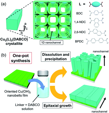
:![[thin space (1/6-em)]](https://www.rsc.org/images/entities/char_2009.gif) DABCO (Fig. 1b). We also show the fabrication of oriented Cu2(linker)2DABCO MOF patterns, where the direction of 1D nanochannels is controllable at individual locations on the same substrate. These Cu2(linker)2DABCO MOF films and patterns with controlled orientation are important steps towards the development of MOF film-based applications such as sensors and electrical/optical devices because functionalities derived from the accommodated guest species in their 1D nanochannels are optimized for the rational direction on the desired substrate for the device fabrication.38,39
DABCO (Fig. 1b). We also show the fabrication of oriented Cu2(linker)2DABCO MOF patterns, where the direction of 1D nanochannels is controllable at individual locations on the same substrate. These Cu2(linker)2DABCO MOF films and patterns with controlled orientation are important steps towards the development of MOF film-based applications such as sensors and electrical/optical devices because functionalities derived from the accommodated guest species in their 1D nanochannels are optimized for the rational direction on the desired substrate for the device fabrication.38,39
Methods
Materials
H2(1,4-NDC) (1,4-naphthalenedicarboxylic acid), H2BPDC (4,4′-biphenyldicarboxylic acid), 1,4-diazabicyclo[2.2.2]octane (DABCO), and azobenzene were purchased from Tokyo Chemical Industry Co., Ltd. H2BDC (1,4-benzenedicarboxylic acid), H2(2,6-NDC) (2,6-naphthalenedicarboxylic acid), methanol, DMF (N,N-dimethylformamide) (99.5%), and acetic acid (99.7%) were purchased from FUJIFILM Wako Pure Chemical Corporation. All reactants were used without any further purification.Synthesis of Cu2(linker)2DABCO oriented film under conditions that favour dissolution and precipitation
Oriented Cu(OH)2 nanobelt films on substrates were prepared according to a previously reported method.33 The conversion from Cu(OH)2 nanobelts to Cu2(1,4-NDC)2DABCO was performed at 70 °C by immersing the copper hydroxide nanobelt film in 10 mL of methanol solution containing 1,4-H2NDC (16 mM) and DABCO (4 mM). After 1 hour, the product was removed from the solution and washed with ethanol, and then dried in air. The Cu2(BDC)2DABCO and Cu2(2,6-NDC)2DABCO oriented films were synthesized in a mixed solvent (5 mL of methanol and 5 mL of DMF) containing the corresponding organic linkers (32 mM) and DABCO (8 mM) at 70 °C for 30 min. The Cu2(BPDC)2DABCO oriented film was prepared in a mixed solvent (5 mL of methanol and 5 mL of DMF) containing H2BPDC (16 mM) and DABCO (8 mM) at 70 °C for 72 hours.Synthesis of Cu2(linker)2DABCO oriented film under epitaxial growth conditions
The conversion from Cu(OH)2 nanobelts to Cu2(1,4-NDC)2DABCO was performed at 70 °C by immersing the copper hydroxide nanobelt film in 10 mL of methanol solution containing 1,4-H2NDC (16 mM) and DABCO (1024 mM). After 3 hours, the product was removed from the solution and washed with ethanol, and then dried in air. The synthesis of Cu2(BDC)2DABCO and Cu2(2,6-NDC)2DABCO was conducted using different organic linker and pillar concentrations: 4 mM H2BDC and 256 mM DABCO for Cu2(BDC)2DABCO and 1 mM 2,6-H2NDC and 64 mM DABCO for Cu2(2,6-NDC)2DABCO. The Cu2(BPDC)2DABCO oriented film was prepared in 10 mL of methanol solution containing H2BPDC (4 mM), DABCO (256 mM), and acetic acid (35 mM) at 60 °C for 3 hours.Introduction of azobenzene into the Cu2(BPDC)2DABCO oriented film
The pores of the Cu2(BPDC)2DABCO oriented film were activated under high vacuum (∼20 Pa) at 140 °C overnight. Then, the activated film was filled with azobenzene into borosilicate glass tubes. The glass tube was then evacuated (∼10 Pa) and flame sealed to give a closed system for a vacuum vapor-phase infiltration process. The sealed ampules were placed inside a convection oven at 140 °C overnight. Excess azobenzene on the film was then removed under vacuum (∼10 Pa) at 140 °C for 30 min for obtaining the AZB-loaded Cu2(BPDC)2DABCO. This infiltration process was performed according to a reported method.20Characterization
Morphologies of the samples were observed using a field-emission scanning electron microscope (FE-SEM: S-4800, Hitachi High-Tech Corporation, Japan) (with an electrically conducting metal coating). The conversion kinetics were investigated by Fourier transform infrared spectroscopy (FT-IR: ALPHA FT-IR spectrometer, Bruker Optik GmbH, Germany). Crystal phases of the obtained samples were identified by X-ray diffraction (Smart Lab, Rigaku Corporation, Japan) using CuKα radiation (λ = 0.154 nm). The degree of orientation was investigated by azimuthal angle dependence of intensity profiles (φ scan). N2 adsorption–desorption isotherms at −196 °C were obtained on a volumetric gas adsorption apparatus (BELSORP-mini II, Bel Japan Inc., Japan). Prior to the measurements, sample powders were pre-treated at 140 °C under vacuum conditions overnight. Specific surface area was estimated by the Brunauer–Emmett–Teller (BET) method. The polarization dependence of absorbance for a Cu2(BPDC)2DABCO oriented film before and after azobenzene infiltration was evaluated using a UV/Vis spectrophotometer (V-670, JASCO Corporation, Japan) with an integrating sphere in a reflection mode by rotating the polarization of the incident light every 15° (rotation intervals) (see Fig. S1†). The incident light was perpendicularly irradiated on the film surface.Results and discussion
Cu2(linker)2DABCO films were fabricated on aligned Cu(OH)2 nanobelts via a one-pot method in which Cu(OH)2 nanobelts oriented on Si substrates were reacted with a selected organic linker and DABCO in methanol at 70 °C. In this reaction, Cu(OH)2 serves as a sacrificial substrate for MOF growth. We hypothesized that the MOF growth process could be controlled by simply changing the linker![[thin space (1/6-em)]](https://www.rsc.org/images/entities/char_2009.gif) :
:![[thin space (1/6-em)]](https://www.rsc.org/images/entities/char_2009.gif) DABCO molar ratio in the reaction solution where linker and DABCO act as acid and base, respectively (Fig. 1b). At high linker/DABCO ratios, continuous Cu(OH)2 dissolution and MOF precipitation are favoured as the excess carboxylic acid-functionalised linker lowers the solution pH; Cu(OH)2 is known to dissolve under acidic conditions. Conversely, at low linker/DABCO ratios, epitaxial growth of Cu2(linker)2DABCO on Cu(OH)2 is favoured as, under basic conditions, Cu(OH)2 is stable, allowing the organic linkers to interact with the ‘Cu–OH’ moieties on the nanobelt surface.35,40 Close matching between the Cu2(linker)2DABCO and Cu(OH)2 lattices is required for the epitaxial growth to occur. Indeed, the family of Cu2(linker)2DABCO MOFs where linker = BDC, 1,4-NDC, 2,6-NDC, and BPDC possess lattice parameters (a and c axes) that closely match those (or a whole number multiple) of Cu(OH)2 (Fig. S2†); BDC and 1,4-NDC: 2.85%, 2,6-NDC: 2.74%, BPDC: 4.56%.15,41 Thus, under low linker/DABCO ratios this series of MOFs should grow epitaxially on a Cu(OH)2 surface.
DABCO molar ratio in the reaction solution where linker and DABCO act as acid and base, respectively (Fig. 1b). At high linker/DABCO ratios, continuous Cu(OH)2 dissolution and MOF precipitation are favoured as the excess carboxylic acid-functionalised linker lowers the solution pH; Cu(OH)2 is known to dissolve under acidic conditions. Conversely, at low linker/DABCO ratios, epitaxial growth of Cu2(linker)2DABCO on Cu(OH)2 is favoured as, under basic conditions, Cu(OH)2 is stable, allowing the organic linkers to interact with the ‘Cu–OH’ moieties on the nanobelt surface.35,40 Close matching between the Cu2(linker)2DABCO and Cu(OH)2 lattices is required for the epitaxial growth to occur. Indeed, the family of Cu2(linker)2DABCO MOFs where linker = BDC, 1,4-NDC, 2,6-NDC, and BPDC possess lattice parameters (a and c axes) that closely match those (or a whole number multiple) of Cu(OH)2 (Fig. S2†); BDC and 1,4-NDC: 2.85%, 2,6-NDC: 2.74%, BPDC: 4.56%.15,41 Thus, under low linker/DABCO ratios this series of MOFs should grow epitaxially on a Cu(OH)2 surface.
To further investigate the effect of linker![[thin space (1/6-em)]](https://www.rsc.org/images/entities/char_2009.gif) :
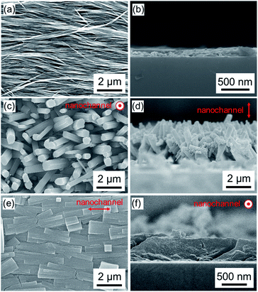
:![[thin space (1/6-em)]](https://www.rsc.org/images/entities/char_2009.gif) DABCO molar ratio on crystal growth processes, we synthesized Cu2(1,4-NDC)2DABCO employing varied concentrations of 1,4-H2NDC and DABCO from oriented Cu(OH)2 nanobelt films, the thickness of which was ca. 220 nm (Fig. 2a and b, and Fig. S3†). We examined the morphologies of the resulting films using scanning electron microscopy (SEM). Close inspection of the images (Fig. 2 and Fig. S4†) clearly reveals that the linker
DABCO molar ratio on crystal growth processes, we synthesized Cu2(1,4-NDC)2DABCO employing varied concentrations of 1,4-H2NDC and DABCO from oriented Cu(OH)2 nanobelt films, the thickness of which was ca. 220 nm (Fig. 2a and b, and Fig. S3†). We examined the morphologies of the resulting films using scanning electron microscopy (SEM). Close inspection of the images (Fig. 2 and Fig. S4†) clearly reveals that the linker![[thin space (1/6-em)]](https://www.rsc.org/images/entities/char_2009.gif) :
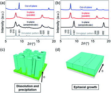
:![[thin space (1/6-em)]](https://www.rsc.org/images/entities/char_2009.gif) DABCO molar ratio has a significant effect on the morphologies of the resultant MOF films. Under linker-rich conditions favouring dissolution and precipitation, the elongated brick shape MOF crystals were aligned perpendicularly to the substrate (Fig. 2c and d). However, when the concentration of DABCO is increased (to 1024 mM from 32 mM), the elongated brick shape MOFs tend to align parallel to the substrate (parallel to the long axis of the original Cu(OH)2 nanobelts), affording a highly oriented film (Fig. 2e and f and Fig. S4†). Homogeneous films were obtained under both synthesis conditions (see Fig. S5†). The crystallographic structure and orientation of the Cu2(1,4-NDC)2DABCO were confirmed by X-ray diffraction (XRD) experiments using previously reported protocols that allow crystallographic orientation along all three axes to be examined (Fig. 3).33,42,43 For the film synthesized under linker-rich conditions, the intense (00l) diffraction signal of Cu2(1,4-NDC)2DABCO in the out-of-plane XRD pattern indicates that the (00l) face of the MOF is parallel to the substrate (Fig. 3a and S6†). Intense (h00) and (0k0) diffraction signals are similarly detected in the two types of in-plane XRD measurements, suggesting a random crystal orientation in the in-plane direction. The interpretation of these results is that there is no epitaxial relationship between the Cu(OH)2 and Cu2(1,4-NDC)2DABCO MOF under linker-rich conditions. Furthermore, these data confirm that the 1D nanochannels (corresponding to the c axis of the MOF) of the film align perpendicularly to the substrate (Fig. 3c). For the film synthesized under conditions that favour epitaxial growth (higher concentrations of DABCO) (Fig. 3b), an intense (0k0) diffraction signal is observed at 2θ = ∼8.2° in the out-of-plane XRD measurement. In addition, the (h00) and (00l) diffraction signals detected in both of the in-plane XRD measurements show a distinct angular dependence. These data indicate that the (h00) and (00l) faces of the MOF crystals are aligned, over the entire surface, orthogonally to each other and perpendicularly to the substrate. This alignment is further confirmed by the azimuthal angle dependence of intensity profiles (φ scan) (Fig. S7†). Collectively, the comprehensive XRD experiments confirm that the 1D nanochannels in the film synthesized under the epitaxial growth conditions are oriented parallel to the substrate (Fig. 3d). The direction of the 1D nanochannels (c axis of the MOF) is determined by the a axis of the original Cu(OH)2, which is consistent with the lattice matching between the Cu(OH)2 and Cu2(1,4-NDC)2DABCO MOF. We note that all the XRD experiments were performed on MOF films grown on substrates exceeding 15 × 15 mm2. This shows that the MOF crystals are oriented over the entire surface and that the direction of the 1D nanochannels is controllable, by simple optimization of the synthetic conditions. It should be mentioned that homogeneous films on macroscopic scales were obtained under the conditions that favour dissolution and precipitation (16 mM 1,4-H2NDC and 4 mM DABCO) and epitaxial growth (16 mM 1,4-H2NDC and 1024 mM DABCO). Lastly the 1D nanochannels were examined by 77 K N2 gas adsorption analysis (Fig. S8†). The isotherm is type I, indicating that the MOF is microporous. BET analysis of the data afforded a specific surface area of 984.29 m2 g−1.
DABCO molar ratio has a significant effect on the morphologies of the resultant MOF films. Under linker-rich conditions favouring dissolution and precipitation, the elongated brick shape MOF crystals were aligned perpendicularly to the substrate (Fig. 2c and d). However, when the concentration of DABCO is increased (to 1024 mM from 32 mM), the elongated brick shape MOFs tend to align parallel to the substrate (parallel to the long axis of the original Cu(OH)2 nanobelts), affording a highly oriented film (Fig. 2e and f and Fig. S4†). Homogeneous films were obtained under both synthesis conditions (see Fig. S5†). The crystallographic structure and orientation of the Cu2(1,4-NDC)2DABCO were confirmed by X-ray diffraction (XRD) experiments using previously reported protocols that allow crystallographic orientation along all three axes to be examined (Fig. 3).33,42,43 For the film synthesized under linker-rich conditions, the intense (00l) diffraction signal of Cu2(1,4-NDC)2DABCO in the out-of-plane XRD pattern indicates that the (00l) face of the MOF is parallel to the substrate (Fig. 3a and S6†). Intense (h00) and (0k0) diffraction signals are similarly detected in the two types of in-plane XRD measurements, suggesting a random crystal orientation in the in-plane direction. The interpretation of these results is that there is no epitaxial relationship between the Cu(OH)2 and Cu2(1,4-NDC)2DABCO MOF under linker-rich conditions. Furthermore, these data confirm that the 1D nanochannels (corresponding to the c axis of the MOF) of the film align perpendicularly to the substrate (Fig. 3c). For the film synthesized under conditions that favour epitaxial growth (higher concentrations of DABCO) (Fig. 3b), an intense (0k0) diffraction signal is observed at 2θ = ∼8.2° in the out-of-plane XRD measurement. In addition, the (h00) and (00l) diffraction signals detected in both of the in-plane XRD measurements show a distinct angular dependence. These data indicate that the (h00) and (00l) faces of the MOF crystals are aligned, over the entire surface, orthogonally to each other and perpendicularly to the substrate. This alignment is further confirmed by the azimuthal angle dependence of intensity profiles (φ scan) (Fig. S7†). Collectively, the comprehensive XRD experiments confirm that the 1D nanochannels in the film synthesized under the epitaxial growth conditions are oriented parallel to the substrate (Fig. 3d). The direction of the 1D nanochannels (c axis of the MOF) is determined by the a axis of the original Cu(OH)2, which is consistent with the lattice matching between the Cu(OH)2 and Cu2(1,4-NDC)2DABCO MOF. We note that all the XRD experiments were performed on MOF films grown on substrates exceeding 15 × 15 mm2. This shows that the MOF crystals are oriented over the entire surface and that the direction of the 1D nanochannels is controllable, by simple optimization of the synthetic conditions. It should be mentioned that homogeneous films on macroscopic scales were obtained under the conditions that favour dissolution and precipitation (16 mM 1,4-H2NDC and 4 mM DABCO) and epitaxial growth (16 mM 1,4-H2NDC and 1024 mM DABCO). Lastly the 1D nanochannels were examined by 77 K N2 gas adsorption analysis (Fig. S8†). The isotherm is type I, indicating that the MOF is microporous. BET analysis of the data afforded a specific surface area of 984.29 m2 g−1.
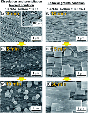
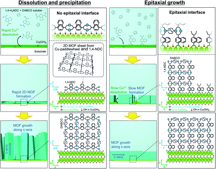
To gain insight into the evolution of the crystal growth processes, we examined both MOF synthesis conditions via SEM: high linker concentration (dissolution and precipitation regime) and high DABCO concentration (epitaxial growth regime). Fig. 4 shows that MOF synthesis at high linker concentrations leads to nanosheets that are formed on the Cu(OH)2 nanobelts after only 3 min. These nanosheets are considered as two-dimensional square lattices composed of Cu paddle-wheel units linked by 1,4-NDC linkers (see Fig. 4a and the XRD experiments in Fig. S9†).31,42 These 2D MOF sheets show no morphological correlation with the nanobelts, suggesting that there is no epitaxial interface between Cu(OH)2 and the 2D MOF, further confirming the XRD results (Fig. 3). At longer reaction times, MOF growth perpendicular to the surface of the substrate is observed. Presumably, at this stage DABCO is being accommodated in the structure as a pillaring agent (Fig. 4c and e) because the peak ascribed to the (00l) diffraction signal in the out-of-plane XRD pattern increases with increasing reaction time (see Fig. S10†). In contrast, under reaction conditions that favour the epitaxial growth, no MOF growth can be detected at the surface of Cu(OH)2 nanobelts after a reaction time of 10 min (Fig. 4b). At 15 min, the growth of cubic Cu2(1,4-NDC)2DABCO crystals parallel (or perpendicular) to the longitudinal axis of Cu(OH)2 nanobelts is observed (Fig. 4d). This result shows that the MOF crystallites grow epitaxially on Cu(OH)2 in the initial growth phase and continue to grow along the longitudinal axis of the Cu(OH)2 nanobelts until they connect with neighbouring crystals (Fig. 4f). A time-course SEM investigation indicates that the MOF crystals form more rapidly at high linker concentrations that yield fast dissolution of the Cu(OH)2 substrate (see Fig. S11†). Indeed, the faster consumption of Cu(OH)2 was observed under the linker-rich conditions (acidic conditions), especially at the early stage of reaction (e.g., 30 min). The initial solution pH for linker-rich and DABCO-rich conditions was shown to be 4.0 and 9.0 using pH indicator paper, respectively (see Fig. S12†). Under both conditions, the solution pH did not change after the reaction. This is presumably because the amount of Cu(OH)2 on the substrate (0.07 mg cm−2, 0.16 mg (1.6 μmol) on 15 × 15 mm2) is insufficient to change the pH of the solution. We performed a control experiment to examine the reactivity of Cu(OH)2 at different concentrations of DABCO in MeOH. We found that Cu(OH)2 does not dissolve, and as a consequence reacts in DABCO solutions of varied concentrations (4, 16, 128 and 1024 mM) (see Fig. S13†).
Based on these XRD and SEM results, we propose the following MOF growth models under conditions of high linker and high DABCO concentrations (Fig. 5). Under the linker-rich conditions favouring dissolution and precipitation, rapid dissolution of Cu(OH)2 occurs. The liberated Cu2+ ions react with the organic linker at the surface of the Cu(OH)2 nanobelts to form two-dimensional MOFs, Cu2(1,4-NDC)2, with the basal face of the crystal parallel to the nanobelts. Indeed, rapid dissolution of Cu(OH)2 was observed only under acidic conditions (see Fig. S14†). This growth mechanism does not afford an epitaxial relationship between the Cu(OH)2 and the 2D MOF. The nascent 2D MOF sheets then grow perpendicular to the surface of the nanobelts via the pillaring agent, DABCO. We note that the oriented growth perpendicular to the substrate is often observed for one-dimensional elongated inorganic nanomaterials synthesized via a similar crystal growth process.44–46 Under basic conditions with high DABCO concentration, the deprotonated organic linkers directly interact with the surface Cu–OH moieties of the Cu(OH)2 nanobelts through hydrogen bonding interactions,35,40 facilitating the epitaxial MOF growth oriented along the in-plane direction. These proposed growth mechanisms are supported by experiments where the linker![[thin space (1/6-em)]](https://www.rsc.org/images/entities/char_2009.gif) :
:![[thin space (1/6-em)]](https://www.rsc.org/images/entities/char_2009.gif) DABCO molar ratio was fixed and the solution acidity was modified (see Fig. S15 and S16†). As anticipated, acidifying the reaction solution induced the dissolution of Cu(OH)2, resulting in the growth of MOF crystals perpendicular to the surface of the Cu(OH)2 substrate, while the addition of a base suppressed the dissolution of Cu(OH)2, leading to the epitaxial MOF growth. Furthermore, the MOF growth mechanism is independent of the carboxylate linker. Orientation-controlled Cu2(linker)2DABCO films were successfully synthesized using a variety of linkers including BDC, 2,6-NDC, and BPDC (Fig. 6). The crystallographic orientation was confirmed by XRD investigations (see Fig. S17†), showing that the Cu2(linker)2DABCO MOFs grow with the same crystallographic orientation as that of Cu2(1,4-NDC)2DABCO under both growth conditions.
DABCO molar ratio was fixed and the solution acidity was modified (see Fig. S15 and S16†). As anticipated, acidifying the reaction solution induced the dissolution of Cu(OH)2, resulting in the growth of MOF crystals perpendicular to the surface of the Cu(OH)2 substrate, while the addition of a base suppressed the dissolution of Cu(OH)2, leading to the epitaxial MOF growth. Furthermore, the MOF growth mechanism is independent of the carboxylate linker. Orientation-controlled Cu2(linker)2DABCO films were successfully synthesized using a variety of linkers including BDC, 2,6-NDC, and BPDC (Fig. 6). The crystallographic orientation was confirmed by XRD investigations (see Fig. S17†), showing that the Cu2(linker)2DABCO MOFs grow with the same crystallographic orientation as that of Cu2(1,4-NDC)2DABCO under both growth conditions.
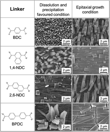 | ||
| Fig. 6 SEM images of Cu2(linker)2DABCO (linker = BDC, 1,4-NDC, 2,6-NDC, and BPDC) oriented films under the conditions favouring dissolution and precipitation, and epitaxial growth. | ||
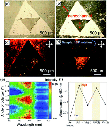
Although fabrication methods have been reported that offer control of the out-of-plane orientation of MOF films,25–30,47,48 those approaches require specific organic molecules as a buffer layer on a substrate to control the orientation, which limits the substrates that can be employed. Owing to the use of Cu(OH)2 nanobelts for MOF growth, precisely aligned MOF films can be achieved on any substrate including conductive indium tin oxide (ITO) coated glass substrates and polymeric curved or flexible surfaces (see Fig. S18†). In addition to substrate versatility, here we show that this approach allows for the fabrication of oriented MOF patterns, in which the direction of 1D nanochannels can be controlled in the desired directions at the desired locations, because the direction of 1D nanochannels is determined by the a axis of the pre-deposited Cu(OH)2 (Fig. 7a–d). The oriented Cu2(1,4-NDC)2DABCO MOF patterns were fabricated from an oriented Cu(OH)2 nanobelt film with patterns, in which the a axis of the pre-deposited Cu(OH)2 nanobelt on the outside of a large triangle aligns in a diagonal line from the upper left to the lower right and that on the inside of a small triangle aligns in a vertical line (Fig. 7a). The Cu(OH)2 pattern was prepared by two deposition processes: (1) deposition on the smaller triangle where the outside of the triangle was covered with scotch tape, and (2) deposition on the outside of the larger triangle where the inside was covered with scotch tape. The pre-patterned Cu(OH)2 structure was preserved after conversion into the MOF via the epitaxial growth strategy (Fig. 7b). Polarization optical micrographs confirm that the direction of 1D nanochannels can be controlled at individual locations on the same substrate (see the triangular patterns in Fig. 7a–d). The macroscopically aligned 1D nanochannel arrays can afford an alignment of guests to exploit anisotropic properties. To this end we incorporated a dye molecule, trans-azobenzene (AZB), as an optical probe in the oriented Cu2(BPDC)2DABCO films via a vacuum vapor-phase infiltration according to a reported procedure.20 The alignment of AZB was probed by monitoring the polarization-dependent UV/Vis absorption, where the polarization of the incident light was rotated every 15° (rotation intervals). The difference absorption spectra before and after the AZB infiltration showed clear polarization dependence (Fig. 7e and Fig. S19†). Strong absorption ascribed to AZB at around 360 nm was observed when light polarization was parallel to the 1D nanochannels in the Cu2(BPDC)2DABCO oriented film (at 0, 180 and 360°). Such a unique polarization-dependent absorption was not observed in the randomly oriented film (see Fig. S20†). This result clearly confirms that the accommodated AZB aligns along the 1D nanochannels. It should be noted that the investigated area on the oriented film for the UV/Vis measurement exceeded 30 mm2, proving macroscopic alignment of the guest molecules in the oriented MOF film. Moreover, it was found that AZB dyes in the Cu2(BPDC)2DABCO oriented film were capable of photo-induced isomerization from the trans to the cis form by UV light irradiation and vice versa by visible light irradiation (Fig. 7f), and interestingly the alignment of the accommodated AZB dyes was retained after repeated trans–cis isomerization (see Fig. S21†). In summary these results demonstrated that the 1D nanochannel arrays in the Cu2(BPDC)2DABCO oriented film allow for macroscopic alignment of guest molecules.
Conclusions
In conclusion, we have investigated the effect of carboxylic acid-functionalised linker![[thin space (1/6-em)]](https://www.rsc.org/images/entities/char_2009.gif) :
:![[thin space (1/6-em)]](https://www.rsc.org/images/entities/char_2009.gif) DABCO ratio, which is related to the solution acidity, on the MOF crystal growth process in the synthesis system of pillar-layered Cu2(linker)2DABCO MOF from Cu(OH)2. Under carboxylic acid-functionalised linker rich conditions, the acidic reaction solution induced the dissolution of Cu(OH)2, resulting in the growth of MOF crystals perpendicular to the surface of the Cu(OH)2 substrate where the 1D nanochannels (corresponding to the c axis of the MOF) align perpendicularly to the substrate. Conversely, at low linker/DABCO ratios, epitaxial growth of Cu2(linker)2DABCO on Cu(OH)2 was favoured, which resulted in the growth of elongated brick shape MOF crystals parallel to the substrate. Since the direction of the 1D nanochannels (c axis of the MOF) is determined by the a axis of the original Cu(OH)2 under the epitaxial growth conditions, precisely aligned MOF patterns where the direction of 1D nanochannels can be controlled in the desired directions at individual locations were also fabricated from Cu(OH)2 nanobelt films with patterns. We also showed how the 1D nanochannels can orient guest molecules at commercially relevant scales in the 1D nanochannel arrays. These Cu2(linker)2DABCO MOF films and patterns with controlled orientation will make a significant contribution to the development of MOF film-based applications.
DABCO ratio, which is related to the solution acidity, on the MOF crystal growth process in the synthesis system of pillar-layered Cu2(linker)2DABCO MOF from Cu(OH)2. Under carboxylic acid-functionalised linker rich conditions, the acidic reaction solution induced the dissolution of Cu(OH)2, resulting in the growth of MOF crystals perpendicular to the surface of the Cu(OH)2 substrate where the 1D nanochannels (corresponding to the c axis of the MOF) align perpendicularly to the substrate. Conversely, at low linker/DABCO ratios, epitaxial growth of Cu2(linker)2DABCO on Cu(OH)2 was favoured, which resulted in the growth of elongated brick shape MOF crystals parallel to the substrate. Since the direction of the 1D nanochannels (c axis of the MOF) is determined by the a axis of the original Cu(OH)2 under the epitaxial growth conditions, precisely aligned MOF patterns where the direction of 1D nanochannels can be controlled in the desired directions at individual locations were also fabricated from Cu(OH)2 nanobelt films with patterns. We also showed how the 1D nanochannels can orient guest molecules at commercially relevant scales in the 1D nanochannel arrays. These Cu2(linker)2DABCO MOF films and patterns with controlled orientation will make a significant contribution to the development of MOF film-based applications.
Conflicts of interest
There are no conflicts to declare.Acknowledgements
The present work was partially supported by grants-in-aid from the Ministry of Education, Culture, Sports, Science and Technology (MEXT), administered by the Japan Society for the Promotion of Science (JSPS), and also by JST, PRESTO Grant Number JPMJPR19I3, Japan. K. O. acknowledges financial support from the Izumi Science and Technology Foundation. P. F. acknowledges the European Union's Horizon 2020 programme (FP/2014-2020)/ERC Grant Agreement no. 771834 – POPCRYSTAL.Notes and references
- J. Xu, H. C. Wu, C. Zhu, A. Ehrlich, L. Shaw, M. Nikolka, S. Wang, F. Molina-Lopez, X. Gu, S. Luo, D. Zhou, Y. H. Kim, G. J. N. Wang, K. Gu, V. R. Feig, S. Chen, Y. Kim, T. Katsumata, Y. Q. Zheng, H. Yan, J. W. Chung, J. Lopez, B. Murmann and Z. Bao, Nat. Mater., 2019, 18, 594–601 CrossRef CAS PubMed.
- J. Xu, S. Wang, G. J. N. Wang, C. Zhu, S. Luo, L. Jin, X. Gu, S. Chen, V. R. Feig, J. W. F. To, S. Rondeau-Gagné, J. Park, B. C. Schroeder, C. Lu, J. Y. Oh, Y. Wang, Y. H. Kim, H. Yan, R. Sinclair, D. Zhou, G. Xue, B. Murmann, C. Linder, W. Cai, J. B. H. Tok, J. W. Chung and Z. Bao, Science, 2017, 355, 59–64 CrossRef CAS PubMed.
- T. Yokota, T. Kajitani, R. Shidachi, T. Tokuhara, M. Kaltenbrunner, Y. Shoji, F. Ishiwari, T. Sekitani, T. Fukushima and T. Someya, Nat. Nanotechnol., 2018, 13, 139–144 CrossRef CAS PubMed.
- K. Hisano, M. Aizawa, M. Ishizu, Y. Kurata, W. Nakano, N. Akamatsu, C. J. Barrett and A. Shishido, Sci. Adv., 2017, 3, e1701610 CrossRef PubMed.
- T. J. White and D. J. Broer, Nat. Mater., 2015, 14, 1087–1098 CrossRef CAS PubMed.
- S. Liu, W. M. Wang, A. L. Briseno, S. C. B. Mannsfeld and Z. Bao, Adv. Mater., 2009, 21, 1217–1232 CrossRef CAS.
- T. Wang, L. Gao, J. Hou, S. J. A. Herou, J. T. Griffiths, W. Li, J. Dong, S. Gao, M. M. Titirici, R. V. Kumar, A. K. Cheetham, X. Bao, Q. Fu and S. K. Smoukov, Nat. Commun., 2019, 10, 1–9 CrossRef PubMed.
- L. Salvati Manni, S. Assenza, M. Duss, J. J. Vallooran, F. Juranyi, S. Jurt, O. Zerbe, E. M. Landau and R. Mezzenga, Nat. Nanotechnol., 2019, 14, 609–615 CrossRef CAS PubMed.
- B. Le Ouay and T. Uemura, Isr. J. Chem., 2018, 58, 995–1009 CrossRef CAS.
- Y. Wu, G. Cheng, K. Katsov, S. W. Sides, J. Wang, J. Tang, G. H. Fredrickson, M. Moskovits and G. D. Stucky, Nat. Mater., 2004, 3, 816–822 CrossRef CAS PubMed.
- H. Furukawa, K. E. Cordova, M. O'Keeffe and O. M. Yaghi, Science, 2013, 341, 1230444 CrossRef PubMed.
- Y. Inokuma, S. Yoshioka, J. Ariyoshi, T. Arai, Y. Hitora, K. Takada, S. Matsunaga, K. Rissanen and M. Fujita, Nature, 2013, 495, 461–466 CrossRef CAS PubMed.
- S. Bureekaew, S. Horike, M. Higuchi, M. Mizuno, T. Kawamura, D. Tanaka, N. Yanai and S. Kitagawa, Nat. Mater., 2009, 8, 831–836 CrossRef CAS PubMed.
- J. Yu, Y. Cui, H. Xu, Y. Yang, Z. Wang, B. Chen and G. Qian, Nat. Commun., 2013, 4, 2719 CrossRef PubMed.
- T. Uemura, N. Yanai, S. Watanabe, H. Tanaka, R. Numaguchi, M. T. Miyahara, Y. Ohta, M. Nagaoka and S. Kitagawa, Nat. Commun., 2010, 1, 83 CrossRef PubMed.
- T. Wang, M. Farajollahi, S. Henke, T. Zhu, S. R. Bajpe, S. Sun, J. S. Barnard, J. S. Lee, J. D. W. Madden, A. K. Cheetham and S. K. Smoukov, Mater. Horiz., 2017, 4, 64–71 RSC.
- T. Iizuka, K. Honjo and T. Uemura, Chem. Commun., 2019, 55, 691–694 RSC.
- S. Henke, A. Schneemann and R. A. Fischer, Adv. Funct. Mater., 2013, 23, 5990–5996 CrossRef CAS.
- S. Henke, W. Li and A. K. Cheetham, Chem. Sci., 2014, 5, 2392–2397 RSC.
- N. Yanai, T. Uemura, M. Inoue, R. Matsuda, T. Fukushima, M. Tsujimoto, S. Isoda and S. Kitagawa, J. Am. Chem. Soc., 2012, 134, 4501–4504 CrossRef CAS PubMed.
- G. Distefano, H. Suzuki, M. Tsujimoto, S. Isoda, S. Bracco, A. Comotti, P. Sozzani, T. Uemura and S. Kitagawa, Nat. Chem., 2013, 5, 335–341 CrossRef CAS PubMed.
- H. He, E. Ma, J. Yu, Y. Cui, Y. Lin, Y. Yang, X. Chen, B. Chen and G. Qian, Adv. Opt. Mater., 2017, 5, 1601040 CrossRef.
- N. Yanai, K. Kitayama, Y. Hijikata, H. Sato, R. Matsuda, Y. Kubota, M. Takata, M. Mizuno, T. Uemura and S. Kitagawa, Nat. Mater., 2011, 10, 787–793 CrossRef CAS PubMed.
- N. Yanai, T. Uemura, S. Horike, S. Shimomura and S. Kitagawa, Chem. Commun., 2011, 47, 1722–1724 RSC.
- J. L. Zhuang, M. Kind, C. M. Grytz, F. Farr, M. Diefenbach, S. Tussupbayev, M. C. Holthausen and A. Terfort, J. Am. Chem. Soc., 2015, 137, 8237–8243 CrossRef CAS PubMed.
- B. Liu, M. Tu and R. A. Fischer, Angew. Chem., Int. Ed., 2013, 52, 3402–3405 CrossRef CAS PubMed.
- H. K. Arslan, O. Shekhah, J. Wohlgemuth, M. Franzreb, R. A. Fischer and C. Wöll, Adv. Funct. Mater., 2011, 21, 4228–4231 CrossRef CAS.
- D. J. Li, Q. H. Li, Z. G. Gu and J. Zhang, J. Mater. Chem. A, 2019, 7, 18519–18528 RSC.
- Z. G. Gu, S. Grosjean, S. Bräse, C. Wöll and L. Heinke, Chem. Commun., 2015, 51, 8998–9001 RSC.
- D. Zacher, K. Yusenko, A. Bétard, S. Henke, M. Molon, T. Ladnorg, O. Shekhah, B. Schüpbach, T. Dea Losa Arcos, M. Krasnopolski, M. Meilikhov, J. Winter, A. Terfort, C. Wöll and R. A. Fischer, Chem.–Eur. J., 2011, 17, 1448–1455 CrossRef CAS PubMed.
- T. Tsuruoka, K. Mantani, A. Miyanaga, T. Matsuyama, T. Ohhashi, Y. Takashima and K. Akamatsu, Langmuir, 2016, 32, 6068–6073 CrossRef CAS PubMed.
- T. Ohhashi, T. Tsuruoka, S. Fujimoto, Y. Takashima and K. Akamatsu, Cryst. Growth Des., 2018, 18, 402–408 CrossRef CAS.
- P. Falcaro, K. Okada, T. Hara, K. Ikigaki, Y. Tokudome, A. W. Thornton, A. J. Hill, T. Williams, C. Doonan and M. Takahashi, Nat. Mater., 2017, 16, 342–348 CrossRef CAS PubMed.
- K. Ikigaki, K. Okada, Y. Tokudome, T. Toyao, P. Falcaro, C. J. Doonan and M. Takahashi, Angew. Chem., Int. Ed., 2019, 58, 6886–6890 CrossRef CAS PubMed.
- K. Okada, R. Ricco, Y. Tokudome, M. J. Styles, A. J. Hill, M. Takahashi and P. Falcaro, Adv. Funct. Mater., 2014, 24, 1969–1977 CrossRef CAS.
- K. Okada, S. Sawai, K. Ikigaki, Y. Tokudome, P. Falcaro and M. Takahashi, CrystEngComm, 2017, 19, 4194–4200 RSC.
- K. Ikigaki, K. Okada, Y. Tokudome and M. Takahashi, J. Sol-Gel Sci. Technol., 2019, 89, 128–134 CrossRef CAS.
- P. Falcaro, R. Ricco, C. M. Doherty, K. Liang, A. J. Hill and M. J. Styles, Chem. Soc. Rev., 2014, 43, 5513–5560 RSC.
- I. Stassen, N. Burtch, A. Talin, P. Falcaro, M. Allendorf and R. Ameloot, Chem. Soc. Rev., 2017, 46, 3185–3241 RSC.
- G. Majano and J. Pérez-Ramírez, Adv. Mater., 2013, 25, 1052–1057 CrossRef CAS PubMed.
- H. R. Oswald, A. Reller, H. W. Schmalle and E. Dubler, Acta Crystallogr., Sect. C: Cryst. Struct. Commun., 1990, 46, 2279–2284 CrossRef.
- T. Tsuruoka, S. Furukawa, Y. Takashima, K. Yoshida, S. Isoda and S. Kitagawa, Angew. Chem., Int. Ed., 2009, 48, 4739–4743 CrossRef CAS PubMed.
- S. Furukawa, K. Hirai, K. Nakagawa, Y. Takashima, R. Matsuda, T. Tsuruoka, M. Kondo, R. Haruki, D. Tanaka, H. Sakamoto, S. Shimomura, O. Sakata and S. Kitagawa, Angew. Chem., Int. Ed., 2009, 48, 1766–1770 CrossRef CAS PubMed.
- K. Okada, Y. Tokudome, P. Falcaro, Y. Takamatsu, A. Nakahira and M. Takahashi, Chem. Commun., 2012, 48, 6130–6132 RSC.
- B. Liu and E. S. Aydil, J. Am. Chem. Soc., 2009, 131, 3985–3990 CrossRef CAS PubMed.
- J. Wang, P. Ma and L. Xiang, Mater. Lett., 2015, 141, 118–121 CrossRef CAS.
- M. Yao, J. Xiu, Q. Huang, W. Li, W. Wu, A. Wu, L. Cao, W. Deng, G. Wang and G. Xu, Angew. Chem., Int. Ed., 2019, 58, 14915–14919 CrossRef CAS PubMed.
- M. S. Yao, W. X. Tang, G. E. Wang, B. Nath and G. Xu, Adv. Mater., 2016, 28, 5229–5234 CrossRef CAS PubMed.
Footnote |
| † Electronic supplementary information (ESI) available. See DOI: 10.1039/d0sc02958k |
| This journal is © The Royal Society of Chemistry 2020 |

