 Open Access Article
Cyclic metal(oid) clusters control platinum-catalysed hydrosilylation reactions: from soluble to zeolite and MOF catalysts†
Miguel
Rivero-Crespo‡
*a,
Judit
Oliver-Meseguer
a,
Klaudia
Kapłońska
b,
Piotr
Kuśtrowski
 b,
Emilio
Pardo
 c,
José Pedro
Cerón-Carrasco
 *d and
Antonio
Leyva-Pérez
 *a
*a
aInstituto de Tecnología Química, Universitat Politècnica de València–Consejo Superior de Investigaciones Científicas, Avda. de los Naranjos s/n, 46022, Valencia, Spain. E-mail: miguel_angel.rivero_crespo@org.chem.ethz.ch; anleyva@itq.upv.es; Fax: +34963877809; Tel: +34963877800
bFaculty of Chemistry, Jagiellonian University, Gronostajowa 2, 30-387 Krakow, Poland
cInstituto de Ciencia Molecular (ICMol), Universidad de Valencia, 46980 Paterna, Valencia, Spain
dReconocimiento y Encapsulación Molecular (REM), Universidad Católica de Murcia (UCAM), Spain. E-mail: jpceron@ucam.edu
First published on 6th July 2020
Abstract
The Pt-catalysed addition of silanes to functional groups such as alkenes, alkynes, carbonyls and alcohols, i.e. the hydrosilylation reaction, is a fundamental transformation in industrial and academic chemistry, often claimed as the most important application of Pt catalysts in solution. However, the exact nature of the Pt active species and its mechanism of action is not well understood yet, particularly regarding regioselectivity. Here, experimental and computational studies together with an ad hoc graphical method show that the hydroaddition of alkynes proceeds through Pt–Si–H clusters of 3–5 atoms (metal(oid) association) in parts per million amounts (ppm), which decrease the energy of the transition state and direct the regioselectivity of the reaction. Based on these findings, new extremely-active (ppm) microporous solid catalysts for the hydrosilylation of alkynes, alkenes and alcohols have been developed, paving the way for more environmentally-benign industrial applications.
1 Introduction
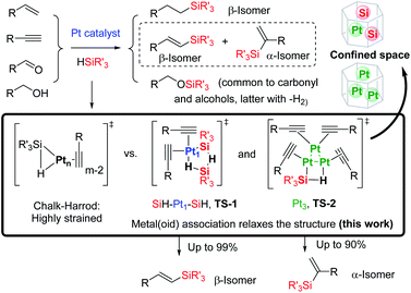
The Pt-catalysed hydrosilylation of alkenes, alkynes, ketones and alcohols, among others, is the method of choice to obtain industrially-useful organosilanes, and unlike hydroborations or hydrostannylations, it only proceeds in the presence of a catalyst.1,2 After 50 years of intensive research, Pt-based catalysts are still the catalysts of choice in both academia and industry due to their inherent and extremely high catalytic activity for this particular reaction, working in parts per million amounts (ppm), at room temperature and with good selectivity in some cases. The fact that the soluble Pt catalyst is not removed after the reaction and that the produced organosilanes are present in industrial silicones in multi-tonnes per year has led to a worldwide spread of the inherently toxic metal.3a Thus, the search for more benign hydrosilylation catalysts, with similar catalytic activity to soluble Pt but which do not remain in the final product, is not only a practical and economical but also a toxicological and environmental concern.3Heterogeneous catalysis is considered a suitable solution when soluble catalysts are toxic and not recyclable, and the more direct and simple approach to heterogenise a soluble catalyst is by supporting it on a simple solid.4 However, examples of truly heterogeneous Pt-supported solid catalysts for hydrosilylation reactions, which mimic the extremely high catalytic activity of Pt in solution, are difficult to find in the literature.5 The main reason for this shortage of reported examples is that the exact nature of the catalytically active Pt species formed in solution during reactions, as well as the structure of key intermediates during the different hydrosilylation reactions, remains mainly unknown, beyond the postulated Chalk–Harrod intermediate shown in Fig. 1.6 The extremely low amount of Pt required to catalyse the hydrosilylation of alkenes and alkynes in solution is well below the detection limits for many experimental techniques, which has precluded conclusive studies on Pt active species. If these catalytically active Pt reaction intermediates are properly detected, the design of new solid catalysts would be easier and more efficient.
Here, we show experimental and computational studies, together with the development of an ad hoc graphical method, which support the association of silane molecules with Pt atoms in solution, prior to or during the rate determining step (rds) of the reaction, to generate 3–5 atom cyclic metal(oid) clusters that facilitate the reaction by providing an alternative low-energy pathway to the classical Chalk–Harrod mechanism. It is also shown here how these cyclic metal(oid) clusters control the electronics and sterics during the alkyne hydrosilylation and govern the final chemo-, regio- and stereoselectivity of the reaction, and with this information in hand, new and extremely active soluble and solid-supported Pt catalysts can be designed not only for the hydrosilylation of alkynes but also for the hydrosilylation of alkenes and alcohols.
2 Results and discussion
2.1. Homogeneous catalysis
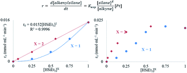
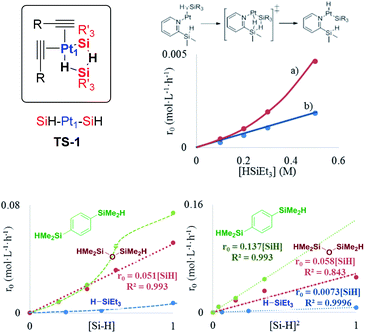
The results in Fig. 2 [see also Fig. S1–S3 in the ESI†] show the rate equations for the hydrosilylation of phenylacetylene 1 with triethylsilane 2 catalysed by either Pt1 or Pt3, obtained from the initial kinetic points, which are r0 = kexp[Pt1][1]−1[2]2 and r0 = kexp[Pt3][1]−1[2], respectively. In other words, the hydrosilylation reaction rate is, in both cases, linearly proportional to the amount of Pt and inversely proportional to the amount of alkyne but, unexpectedly, it is quadratically proportional to the amount of silane for Pt1 but not for Pt3. For the latter, saturation kinetics is observed at high silane concentrations ([2] > 0.50 M). It is noteworthy that the main product for Pt1 is the typical β-(E) alkenylsilane,15 with >95% selectivity, while for Pt3 is the less common α-alkenylsilane,9,16 with >90% selectivity. However, here the formation of both products is equally considered to assess the catalytic activity of the different Pt catalysts.
A Hammett plot for different para-substituted dimethylphenylsilanes prepared by a reported method17 gives a similar negative slope for both catalysts (ρPt1 = −0.50, ρPt3 = −0.60, Fig. S4†), and the kinetic isotope effect (KIE) values for the hydrosilylation of 1 with H(D)SiEt3 are 2.0 and 1.7 ± 0.2 for Pt1 and Pt3 respectively (see further below for a more precise value through the graphical method), which confirm that a positive charge is being built and that the Si–H(D) bond is breaking before or during the rate determining step of the hydrosilylation reaction, for both Pt1 and Pt3 catalysts respectively. However, this catalytic similarity between Pt1 and Pt3 is clearly broken when considering the enthalpy and entropy values in the transition state (ΔH‡ and ΔS‡). Table 1 shows the ΔH‡ and ΔS‡ values for the hydrosilylation reaction of 1 with 2, calculated experimentally with the Eyring–Polanyi equation, and the results show that the Pt1 catalyst significantly decreases both the enthalpy and entropy values (∼50 kJ mol−1 and −190 J K−1 mol−1, respectively, entry 1) relative to Pt3 (∼110 kJ mol−1 and −25 J K−1 mol−1, entry 2), which raises the apparent contradiction that the transition state is more associated for Pt1 than for Pt3. To assess the influence of the alkyne and the silane on the ΔH‡ and ΔS‡ values, the study was expanded to 1-octyne 3 and 1,1,3,3-tetramethyldisiloxane (TMDS) 4, and the results (entries 3–6) show that a different alkyne does not modify the energetics of the transition state while a different silane indeed does. These results fit with the different reaction order found with respect to the Pt atomicity for the silane but not for the alkyne and suggest that not only the nature but also the number of silane molecules is key in the transition state of the hydrosilylation reaction, at least with Pt1.
| Entry | Alkyne/silane | Pt | ΔH‡ (kJ mol−1) | ΔS‡ (J K−1 mol−1) |
|---|---|---|---|---|
| 1 | 1/2 | Pt1 | 53 ± 4 (52 ± 2) | −175 ± 10 (−156 ± 6) |
| 2 | Pt3 | 114 ± 6 (109 ± 2) | −2 ± 16 (5 ± 6) | |
| 3 | 3/2 | Pt1 | 52 ± 3 (54 ± 3) | −171 ± 8 (−168 ± 15) |
| 4 | Pt3 | 103 ± 12 (123 ± 4) | 22 ± 33 (40 ± 17) | |
| 5 | 1/4 | Pt1 | 24 ± 3 (38 ± 2) | −252 ± 9 (−210 ± 20) |
| 6 | Pt3 | 28 ± 3 (41 ± 2) | −242 ± 6 (−188 ± 5) |
In order to confirm these energetic differences, a more accurate graphical method was developed, since the initial rate approximation encounters some limitations in reactions with induction times, catalyst deactivation, late steady state attainment and very fast rates,18 which can be the case here. In this context, Reaction Progress Kinetic Analysis (RPKA)19 and Variable Time Normalization Analysis (VTNA)20 have emerged in recent years as powerful tools to measure reaction orders from catalysed reactions with high precision in few experiments.21 However, both RPKA and VTNA do not cover other kinetic and thermodynamic parameters such as the transition state enthalpy and entropy, linear free energy relationships (LFER) and KIE (Fig. S5†).22 Despite temperature scanning methodologies having been recently developed to calculate energetic activation parameters,22d this methodology is much more complex in terms of instrumentation and data treatment. For all these reasons, and inspired by the simple graphical methodologies mentioned above, a graphical method to calculate the ΔH‡, ΔS‡, Hammett parameter (ρ) and KIE values, using the tools available in our laboratory, was developed here. This new methodology does not only allow the calculation of the energetic values with high precision in few experiments, but also proposes a way to calculate the errors associated with the measurements (see the ESI† for discussion).
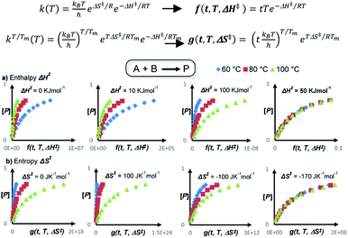
Fig. 3 illustrates the basis of our approach for a simulated bimolecular reaction A + B → P, i.e. the hydrosilylation reaction, with the calculation of the transition state enthalpy and entropy values (ΔH‡ and ΔS‡, see the ESI† for the mathematical model development). The final methodology is very simple and involves representing the product concentration vs. the normalized time-scale f or g(t, T, ΔH‡ or ΔS‡). In this way, the transition state enthalpy ΔH‡ or entropy value ΔS‡ is easily obtained by iterations with any available user graphic software (Excel®, Origin®, …) until all kinetic profiles overlay at different temperatures, which can be done either by just visually, adjusting to a polynomic equation until obtaining the best fit in terms of R2 or by minimizing the Euclidean distance between the data points. The latter approach was used in this work (see the ESI†). This methodology gives the activation parameters directly from raw concentration data, avoiding the propagation of errors associated with the initial rates, which can be as high as ±8% at R2 = 0.997 for the classical method (Fig. S6 and Tables S1–S5†), but only up to ±4% at nearly perfect fittings (R2 > 0.999) for the new graphical method. Noteworthily, the graphical method overrides the experimental distortions arising from induction times, since these induction times are included in the whole kinetic profile, which was validated for a simulated (Fig. S7, S8, Tables S6 and S7†) and a reported related reaction23 (Fig. S9†).
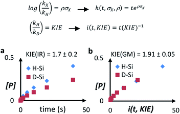
The results of ΔH‡ and ΔS‡ obtained by the graphical method are shown in Table 1 (see also Fig. S10–S15†) and reinforce the conclusions obtained with the traditional kinetic values, i.e. the transition stateis less energetic (lower ΔH‡) and more associated (lower ΔS‡) for Pt1 than for Pt3. Fig. 4 shows that the graphical method can also be applied to find the Hammett parameter (ρ, Fig. S16 and Tables S8–S10†) and KIE values (see the ESI† for discussion), which gives ρ = 0.50 for the Pt1 catalyst and KIE = 1.91(5) for the Pt3 catalyst, exactly the same value as that for Pt1 but with much more precision (see above and Table S11†). These results confirm the energetic and isotopic kinetic data obtained for the hydrosilylation of alkynes with Pt1 and Pt3, and support the hypothesis of metal(oid) Pt–silane cluster formation during the transition state of the reaction.
The occupancy of the free coordinating sites in TS-1 by alkynes is supported by the negative dependence of the hydrosilylation rate on the alkyne concentration, for both Pt1 and Pt3 catalysts, which indicates that the saturation of the coordinative sites of Pt with alkyne molecules occurs at the very beginning of the catalytic cycle, in accordance with the alkynophilic nature of the metal. This hypothesis is supported by the enhanced reaction rate found for electron-rich alkynes (worse π-acceptors), following the order: electron-deficient phenylacetylenes < electron-rich phenylacetylenes < alkyl alkynes, assessed by the negative slope in the Hammett plot (Fig. S18†), and the decrease in the reaction rate when phenylacetylene 1 is added during the hydrosilylation of 1-octyne 3, but not the reverse, in accordance with the stronger π-accepting ability of 1 (Fig. S19†), and the lack of the kinetic isotope effect (KIE) found for deuterated phenylacetylene (1.1 ± 0.1 for both Pt1 and Pt3), which indicates that σ-Pt alkynylide species do not participate in the reaction. Thus, the incoming silane must displace coordinating alkyne molecules in the inner sphere of Pt through σ-interactions,27 to give the key cyclic metalloid cluster.
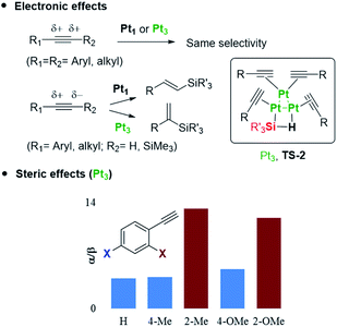
A four-membered metal(oid) cyclic transition state may also be involved for Pt3 clusters, in this case with just one silane molecule, shown in Fig. 6 as TS-2 (see also Fig. 1). The linearity of the rate equation with [2] (see above) supports this intermediate. Furthermore, taking advantage of the different regioselectivity found for Pt3 and the fact that the regioselectivity comes from the electronic effect produced by alkyne polarization, the reactivity of different internal alkynes where the two carbon atoms are electronically similar, was tested. Fig. 6 also shows that no α/β differentiation occurs between Pt1 and Pt3 catalysts while, in contrast, an extremely polarized internal alkyne such as trimethylsilylphenylacetylene 7, where the charge difference between the two carbon atoms is comparable to a terminal alkyne (Table S12†), produces a change in the α/β isomer ratio from 0.37 (Pt1) to 0.60 (Pt3). These results support that the electronics of the alkyne is determinant for the regioselectivity during the Pt3-catalysed hydrosilylation reaction, but not with the Pt1 catalyst.28 Regarding sterics, electronically similar ortho- and para-substituted phenylacetylenes show that the former react less with Pt1 clusters than with Pt3 (Fig. 6, S20 and S21†), and these results make sense considering that the cyclic metal(oid) transition state around Pt1 is more congested than around Pt3, thus enhancing steric effects during the reaction (Fig. S21†).29 The so-called ortho effect, initially described for the hydrostannylation of alkynes30 and associated with higher differences in 13C NMR for internal and external carbon atoms, cannot be invoked here since it is caused not only by electronic but also by steric effects.31 Two-dimensional nuclear magnetic resonance nuclear Overhauser effect spectroscopy (NOESY) of the α-vinylsilane product, deuterated or not, shows that both the anti- and Markovnikov hydrosilylation reactions with Pt1 and Pt3 proceed completely in a syn-fashion (Fig. S22–S24†), which is in accordance with the observed products and previous studies on silylplatination and reductive elimination steps.32
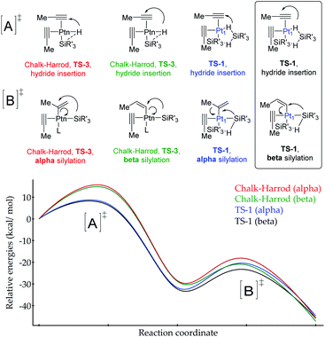
According to the calculations, the proposed TS-1 metal(oid) cluster decreases the barrier for the hydride addition (intermediates [A]) by ca. 10 kcal mol−1 (black and blue lines) with respect to the standard Chalk–Harrod intermediate TS-3 (red and green lines), regardless of the regiochemistry of the product. This stabilization comes from the significantly less constrained environment around the Pt atom when two silane molecules bind and cooperate, compared to the canonical Chalk–Harrod configuration. Furthermore, the smallest energy barrier for the final silylation step (intermediates [B]) corresponds to the formation of the β-isomer through the TS-1 intermediate (black line), and thus the DFT calculations predict the right product after a silane self-assisted hydroplatination process. All these accumulated theoretical outcomes back up the hypothesis of cyclic metal(oid) cluster formation.
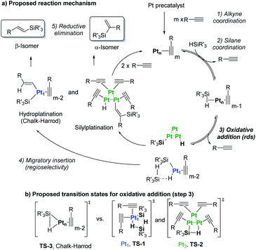 | ||
| Fig. 8 (a) Chalk–Harrod mechanism (n = 1) and the alternative mechanism found in this work (n = 1 and 3). (b) Transition states for the oxidative addition proposed in this study. | ||
Taking into consideration the elementary steps of the mechanism proposed in Fig. 8, validated not only by experimental results but also by computational results and the graphical method, a theoretical kinetic equation for the Markovnikov hydrosilylation of alkynes catalysed by Pt1 can be obtained, using the steady state approximation (Fig. S25† for mathematical development). With the appropriate simplifications, the resulting calculated equation resembles the experimentally obtained equation (vide supra), with the quadratic [silane]2 dependence:
and the same applies for the Pt3 catalyst (Fig. S26†), which gives the expected reaction orders after simplifications:
Therefore, the mechanism in Fig. 8 is supported not only by kinetic, isotopic, thermodynamic and computational data, but also by the theoretical rate equations.
2.2. Heterogeneous catalysis
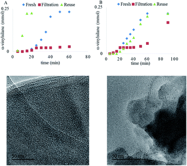
Both Pt1/NaY and Pt3/NaY, in ppm, give the α-vinylsilane product, but while Pt1/NaY showed a long induction time (∼25 minutes) and no leaching of Pt into solution, as assessed by the hot filtration test (Fig. 9A) and ICP analysis (<1% of supported Pt into solution), Pt3/NaY showed, in contrast, a shorter induction and leaching of inactive Pt species into the solution (∼10% measured by ICP), which evolve to active species after 50 minutes (Fig. 9B). In a similar way to Pt3 clusters being formed in situ in solution from simple homogeneous precursors,9,16 we reasoned here that Pt atoms inside Pt1/NaY could also evolve to form Pt3 clusters under reaction conditions, remaining within the zeolitic framework, while the pre-formed Pt3 clusters inside the zeolite Pt3/NaY are less stabilized by the framework and tend to leach out, which converts the Pt3/NaY just to a simple reservoir of Pt.
Fig. 9A also shows that the Pt1/NaY catalyst could be reused without any induction time (up to five times), without loss of activity and with just a small fraction of the confined Pt3 aggregates being converted into nanoparticles (<2 nm),40 according to high resolution transmission electron microscopy (HR-TEM) measurements (Fig. 9, bottom). These results strongly support that the active Pt3 species are formed in situ and stabilized within the zeolite framework, ready to be further reused without leaching. In accordance with the leaching results, the preformed Pt3/NaY sample loses activity and still shows some induction time (Fig. 9B).
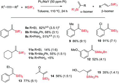
Fig. 10 shows the results for the hydrosilylation reaction of different alkynes and silanes catalysed by Pt1/NaY, and it can be seen that just 1 mg of the zeolite per mmol of alkyne (50 ppm of Pt) is enough to achieve full conversion and good selectivity towards the corresponding α-vinylsilanes, including aromatic (products 8a–c–10 and 12–13) and alkyl alkynes (products 11a,b and 14–15), aromatic (products 8b,c, 11b, 12 and 15) and alkyl silanes (products 8a–11a and 14–14), and also an internal alkyne (product 14). Monosusbtituted phenylsilane PhSiH3 reacts selectively once with an aromatic alkyne to give the corresponding silane 8c in reasonable 51% yield (the rest is β isomer and not polyalkylated silanes), and it does not react with an alkyl alkyne (product 11c). The silane HSi(OEt)3 did not yield the desired product either, in any case, but rather decomposed. The reaction can also be run at room temperature, provided that more solid catalyst (20 mg per mmol of alkyne) is used, and this result indicates that the active and zeolite-stabilized Pt3 species can be formed inside the zeolite without thermal requirements. To our knowledge, this is the first efficient and recyclable solid catalyst for the Markovnikov hydrosilylation of alkynes.41 Previous tests9 showed that Pt/C does not really work as a catalyst to obtain the alpha product but just generate species in solution with low alpha selectivity. Besides, not only the selectivity but also the activity is considerably higher in Pt/zeolites than in Pt/C. At this stage, and in order to gain more information about the Pt species on the solid during the reaction, a 195Pt solid NMR experiment was envisaged; however, the acquisition time to have a reliable result was estimated to be unacceptably long.
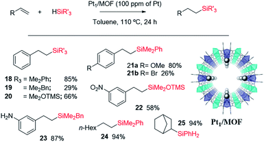
Fig. 11 shows the single crystal X-ray diffractogram of Pt1/MOF, where the single Pt atoms are marked with an arrow.38b As can be seen, the MOF is constituted by ∼1 nm channels with homogeneously distributed isolated Pt atoms stabilized on the framework walls by electronic interactions.35,38b,d This structure resembles that expected in the cavities and channels of the zeolite and, thus, it is not surprising that the Pt1-supported microporous MOF catalyses the hydrosilylation of alkenes similarly or even better than Pt1/NaY does. Fig. 11 also shows the scope for the hydrosilylation of terminal alkenes catalysed by Pt1/MOF, and not only aromatic (products 18–23) but also alkyl alkenes (products 24–25) engage well in the reaction. Different electron poor silanes are reactive, including PhSiH3 as a selective monosilylation partner; however, triethylsilane 2 was not suitable in this case.
A hot filtration test for the hydrosilylation of styrene 16 with the Pt1/MOF catalyst shows that the ∼30% of the catalytic activity comes from active species in solution (Fig. S27,† left); however, most of the catalytic activity lies in the solid under reaction conditions. Furthermore, when one looks at the kinetic profile closely, a short but clear induction time of 5 min can be seen (Fig. S28,† right), an induction time that is not present at all when the hydrosilylation of 16 is catalyzed even by tiny amounts of Karstedt's catalyst in solution, according to our experiments (Fig. S29†). The induction time with Pt1/MOF may indicate that initial Pt1 on the MOF is not the active species and evolves to active Pt1 during the reaction. Coulombic forces are behind the stabilization of Pt on the negatively-charge walls of the microporous solids. Thus subtle electronic modifications of the Pt1 atom by donation of electron density from the solid framework to the metal atom could modulate and ultimately increase the catalytic activity.45 Indeed, by just heating Pt1/NaY in an oven at 200 °C for 1 hour before the reaction, the hydrosilylation of 16 proceeds with full conversion and with the highest TOF measured (entry 9 in Table 2). X-ray photoelectron spectroscopy (XPS) in combination with CO-probe low temperature infrared (IR) measurements of the Pt1/NaY sample calcined at 200 °C show that the amount of Pt(0) increases at least twice with respect to Pt(II) in non-calcined Pt1/NaY and Pt1/MOF (Fig. S29†). These results support the formation of catalytically active, reduced Pt1 species within the microporous catalyst. It should be noted that the Pt1 annotation used here does not necessarily presuppose hardly reduced species, since discussion focuses on Pt atomicity rather than on the exact valence state.
| Entry | Pt catalyst | Yield (%) | TOF0 (h−1) |
|---|---|---|---|
| 1 | Karstedt | 96 | 126 |
| 2 | Pt(acac)2 | 26 | 30 |
| 3 | Pt(NH3)4Cl2·xH2O | 33 | 37 |
| 4 | Pt(COD)(Me)2 | 38 | 43 |
| 5 | Pt/C | 87 | 99 |
| 6 | PtCl2/SiO2 | 37 | 42 |
| 7 | Pt1/MOF | 35 | 42 |
| 8 | Pt1/NaY | 93 | 106 |
| 9 | Pt 1 /NaY (calc. at 200 °C) | 99 | 118 |
| 10 | Pt1/NaY (calc. at 300 °C) | 64 | 76 |
| 11 | Pt1/HY | 61 | 72 |
| 12 | Pt1/CsY | 19 | 22 |
| 13 | Pt3/NaY | 22 | 26 |
Karstedt's catalyst is the only efficient soluble Pt catalyst from those tested (entries 1–4), and considering that Karstedt's catalyst only contains Pt(0) atoms, and that Pt/C is also quite effective (entry 5), it seems that Pt(0) could be the active redox species for the dehydrogenative silylation of alcohols. This hypothesis fits well with the studies above on alkynes and alkenes and also with the lower activity shown by PtCl2/SiO2 and Pt1/MOF (entries 6 and 7) with respect to Pt1/NaY (entry 8), which is able to easily modulate the Pt site by the negatively-charged zeolite framework. Indeed, Pt1/NaY calcined at 200 °C, which tends to reduce the Pt atoms further,38a gives a 99% yield of 27 and the highest initial TOF (entry 9). Calcination at higher temperatures to provoke metal aggregation (entry 10),52 and decreasing or increasing the electronic density of the zeolite with a different charge compensating cation to Na+ (H+ and Cs+, entries 11 and 12 respectively),38a do not improve the catalytic activity and supports the need of fine tuning the Pt site on truly heterogeneous microporous solid catalysts for the hydrosilylation reaction, when leaching does not occur (Fig. S30†). These facts point again to an in situ formation of the Pt catalyst, and having in mind the H-atom bridges found in the metal(oid) cluster intermediates and the decisive effect of the zeolite confined space, it is possible to propose a tentative mechanism for the dehydrogenative silylation of alcohols based on metal(oid) cycles (Fig. S31†).53 Although speculative, this mechanism should be taking into consideration for future catalyst design based on Pt for the dehydrogenative hydrosilylation of alcohols.
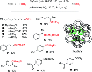
Fig. 12 shows that the Pt1/NaY solid calcined at 200 °C for 1 hour, catalyses the dehydrogenative hydrosilylation of alkyl alcohols (products 28–32, 34 and 36), benzyl alcohols (product 33) and phenol derivatives (products 34 and 37–38) in good yields and with just 100 ppm of Pt, and with different silanes. Interestingly, the disilane H2SiPh2 yields only the monosilylated product without further reaction, and the silane HSi(OEt)3 was also reactive in this case, to give products 30 and 37, respectively, in very good yields. To our knowledge, this is the first Pt-based efficient solid catalyst for the dehydrogenative hydrosilylation of alcohols.
3 Conclusions
The regioselectivity of the Pt-catalysed hydrosilylation of alkynes is controlled by in situ formed cyclic Pt–silane metal(oid) clusters, and while the cluster formed by one Pt atom and two silane molecules leads to the β-(E)-vinylsilane product, the cluster formed by three Pt atoms and one silane molecule leads to the α-vinylsilane product. These cyclic unstrained transition states lower the activation energies of the reaction by facilitating the rate determining step of the reaction, i.e. the oxidative addition of the silane. These Pt intermediates are, in principle, suitable to be stabilized within the nanometric confined space of zeolites and MOFs, and indeed, the Pt-supported solids catalyse very efficiently not only the hydrosilylation of alkynes but also of alkenes and the dehydrogenative hydrosilylation of alcohols, and can be recycled. These results provide a plausible alternative mechanism for the long-accepted Chalk–Harrod mechanism and give tools to design new hydrosilylation reactions based on ppm of Pt, of relevance in industrial chemistry.Conflicts of interest
There are no conflicts of interest to declare.Acknowledgements
Financial support by MINECO through the Severo Ochoa program (SEV-2016-0683), Excellence program (CTQ 2017-86735-P and CTQ 2017-87974-R) and Retos Col. (RTC-2017-6331-5) is acknowledged. E. P. acknowledges the financial support of the European Research Council under the European Union's Horizon 2020 research and innovation program/ERC Grant Agreement No. 814804, MOF-reactors. M. A. R.-C. thanks ITQ for the concession of a contract and J. O. M. thanks the Juan de la Cierva program for the concession of a contract. We thank V. B. dLL. and N. G. G. for performing degree projects in the ITQ labs. This research was partially supported by the supercomputing infrastructure of Poznan Supercomputing Center. The Electron Microscopy Service of the UPV is also acknowledged.Notes and references
- (a) B. M. Trost and Z. T. Ball, Synthesis, 2005, 853–887 CrossRef CASFor a book see (b) B. Marciniec, H. Maciejewski, C. Pietrasuk and P. Pawluc, Hydrosilylation: A Comprehensive review on Recent Advances, Springer, Netherlands, 2009 CrossRef.
- For some recent studies see (a) P.-W. Long, X.-F. Bai, F. Ye, L. Li, Z. Xu, K.-F. Yang, Y.-M. Cui, Z.-J. Zheng and L.-W. Xu, Adv. Synth. Catal., 2018, 360, 2825–2830 CrossRef CAS; (b) A. A. Szymaniak, C. Zhang, J. R. Coombs and J. P. Morken, ACS Catal., 2018, 8, 2897–2901 CrossRef CAS PubMed; (c) C. Dong, Y. Yuan, Y.-M. Cui, Z.-J. Zheng, J. Cao, Z. Xu and L.-W. Xu, Appl. Organomet. Chem., 2018, 32, e4037 CrossRef; (d) Y. Zhu, T. Cao, C. Cao, J. Luo, W. Chen, L. Zheng, J. Dong, J. Zhang, Y. Han, Z. Li, C. Chen, Q. Peng, D. Wang and Y. Li, ACS Catal., 2018, 8, 10004–10011 CrossRef CAS; (e) M. A. Guseva, D. A. Alentiev, E. V. Bermesheva, I. A. Zamilatskovc and M. V. Bermeshev, RSC Adv., 2019, 9, 33029–33037 RSC; (f) L. Chen, I. S. Ali, G. E. Sterbinsky, J. T. L. Gamler, S. E. Skrabalak and S. L. Tait, ChemCatChem, 2019, 11, 2843–2854 CrossRef CAS; (g) J. Walkowiak, K. Salamon, A. Franczyk, K. Stefanowska, J. Szyling and I. Kownacki, J. Org. Chem., 2019, 84, 2358–2365 CrossRef CAS PubMed.
- For a recent review see: (a) J. V. Obligacion and P. J. Chirik, Nat. Rev. Chem., 2018, 2, 15–34 CrossRef CAS PubMedFor a representative example see (b) I. Pappas, S. Treacy and P. J. Chirik, ACS Catal., 2016, 6, 4105–4109 CrossRef CAS.
- A. Corma, C. González-Arellano, M. Iglesias and F. Sánchez, Angew. Chem., Int. Ed., 2007, 46, 7820–7822 CrossRef CAS PubMed.
- For a review see: (a) M. Pagliaro, R. Ciriminna, V. Pandarus and F. Béland, Eur. J. Org. Chem., 2013, 6227–6235 CrossRef CAS; (b) For a representative study see: X. Cui, K. Junge, X. Dai, C. Kreyenschulte, M.-M. Pohl, S. Wohlrab, F. Shi, A. Brückner and M. Beller, ACS Cent. Sci., 2017, 3, 580–585 CrossRef CAS PubMed.
- T. K. Meister, K. Riener, P. Gigler, J. Stohrer, W. A. Herrmann and F. E. Kühn, ACS Catal., 2016, 6, 1274–1284 CrossRef CAS.
- L. N. Lewis, K. G. Sy, G. L. Bryant and P. E. Donahue, Organometallics, 1991, 10, 3750–3759 CrossRef CAS.
- (a) N. Asao, T. Sudo and Y. Yamamoto, J. Org. Chem., 1996, 61, 7654–7655 CrossRef CAS PubMed; (b) L. Yong, K. Kirleis and H. Butenschön, Adv. Synth. Catal., 2006, 348, 833–836 CrossRef CAS; (c) V. S. Sridevi, W. Y. Fan and W. K. Leong, Organometallics, 2007, 26, 1157–1160 CrossRef CAS.
- M. A. Rivero-Crespo, A. Leyva-Perez and A. Corma, Chem.–Eur. J., 2017, 23, 1702–1708 CrossRef CAS PubMed.
- G. Longoni and P. Chini, J. Am. Chem. Soc., 1976, 98, 7225–7231 CrossRef CAS.
- J. C. Calabrese, L. F. Dahl, P. Chini, G. Longoni and S. Martinengo, J. Am. Chem. Soc., 1974, 96, 2614–2616 CrossRef CAS.
- (a) R. S. Tanke and R. H. Crabtree, J. Chem. Soc., Chem. Commun., 1990, 1056–1057 RSC; (b) A. Sato, H. Kinoshita, H. Shinokubo and K. Oshima, Org. Lett., 2004, 6, 2217–2220 CrossRef CAS PubMed; (c) G. de Bo, G. Berthon-Gelloz, B. Tinant and I. E. Markó, Organometallics, 2006, 25, 1881–1890 CrossRef CAS; (d) M. V. Jiménez, J. J. Pérez-Torrente, M. I. Bartolomé, V. Gierz, F. J. Lahoz and L. A. Oro, Organometallics, 2008, 27, 224–234 CrossRef.
- L. Ortega-Moreno, R. Peloso, C. Maya, A. Suárez and E. Carmona, Chem. Commun., 2015, 51, 17008–17011 RSC.
- For induction times directly related to catalytically-active metal cluster formation, see for instance: (a) J. Oliver-Meseguer, J. R. Cabrero-Antonino, I. Dominguez, A. Leyva-Perez and A. Corma, Science, 2012, 338, 1452–1455 CrossRef CAS PubMed; (b) A. Leyva-Pérez, J. Oliver-Meseguer, P. Rubio-Marqués and A. Corma, Angew. Chem., Int. Ed., 2013, 52, 11554–11559 CrossRef PubMed; (c) J. Oliver-Meseguer, L. Liu, S. Garcia-Garcia, C. Canos-Gimenez, I. Dominguez, R. Gavara, A. Domenech-Carbo, P. Concepcion, A. Leyva-Perez and A. Corma, J. Am. Chem. Soc., 2015, 137, 3894–3900 CrossRef CAS PubMed.
- (a) M. A. Esteruelas, M. Oliván, L. A. Oro and J. Tolosa, J. Organomet. Chem., 1995, 487, 143–149 CrossRef CAS; (b) R. Takeuchi, S. Nitta and D. Watanabe, J. Org. Chem., 1995, 60, 3045–3051 CrossRef CAS.
- B. G. M. Rocha, E. A. Valishina, R. S. Chay, M. F. C. Guedes da Silva, T. M. Buslaeva, A. J. L. Pombeiro, V. Y. Kukushkin and K. V. Luzyanin, J. Catal., 2014, 309, 79–86 CrossRef CAS.
- E. J. Rayment, N. Summerhill and E. A. Anderson, J. Org. Chem., 2012, 77, 7052–7060 CrossRef CAS PubMed.
- (a) V. P. Ananikov and I. P. Beletskaya, Organometallics, 2012, 31, 1595–1604 CrossRef CAS; (b) A. V. Astakhov, O. V. Khazipov, A. Y. Chernenko, D. V. Pasyukov, A. S. Kashin, E. G. Gordeev, V. N. Khrustalev, V. M. Chernyshev and V. P. Ananikov, Organometallics, 2017, 36, 1981–1992 CrossRef CAS.
- (a) D. G. Blackmond, Angew. Chem., Int. Ed., 2005, 44, 4302–4320 CrossRef CAS PubMed; (b) D. G. Blackmond, Angew. Chem., 2005, 117, 4374–4393 CrossRef; (c) D. G. Blackmond, J. Am. Chem. Soc., 2015, 137, 10852–10866 CrossRef CAS PubMed.
- (a) J. Burés, Angew. Chem., Int. Ed., 2016, 55, 16084–16087 CrossRef PubMed; (b) J. Burés, Angew. Chem., Int. Ed., 2016, 55, 2028–2031 CrossRef PubMed.
- (a) J. S. Mathew, M. Klussmann, H. Iwamura, F. Valera, A. Futran, E. A. C. Emanuelsson and D. G. Blackmond, J. Org. Chem., 2006, 71, 4711–4722 CrossRef CAS PubMed; (b) M. Colladon, A. Scarso, P. Sgarbossa, R. A. Michelin and G. Strukul, J. Am. Chem. Soc., 2007, 129, 7680–7689 CrossRef CAS PubMed; (c) R. D. Baxter, D. Sale, K. M. Engle, J.-Q. Yu and D. G. Blackmond, J. Am. Chem. Soc., 2012, 134, 4600–4606 CrossRef CAS PubMed; (d) S. B. Kedia and M. B. Mitchell, Org. Process Res. Dev., 2009, 13, 420–428 CrossRef CAS.
- (a) E. V. Anslyn and D. A. Dougherty, Modern Physical Organic Chemistry, University Science Books, 2006 Search PubMed; (b) A. K. Cook and M. S. Sanford, J. Am. Chem. Soc., 2015, 137, 3109–3118 CrossRef CAS PubMed; (c) L. Legnani, G. Prina-Cerai, T. Delcaillau, S. Willems and B. Morandi, Science, 2018, 362, 434–439 CrossRef CAS PubMed; (d) K. C. Aroh and K. F. Jensen, React. Chem. Eng., 2018, 3, 94–101 RSC.
- E. Fernandez, M. A. Rivero-Crespo, I. Dominguez, P. Rubio-Marques, J. Oliver-Meseguer, L. Liu, M. Cabrero-Antonino, R. Gavara, J. C. Hernandez-Garrido, M. Boronat, A. Leyva-Perez and A. Corma, J. Am. Chem. Soc., 2019, 141, 1928–1940 CrossRef CAS PubMed.
- S. Sakaki, N. Mizoe and M. Sugimoto, Organometallics, 1998, 17, 2510–2523 CrossRef CAS.
- (a) M. Tanabe, D. Ito and K. Osakada, Organometallics, 2007, 26, 459–462 CrossRef CAS; (b) B. J. Anderson, J. A. Keith and M. S. Sigman, J. Am. Chem. Soc., 2010, 132, 11872–11874 CrossRef CAS PubMed; (c) E. Tkatchouk, N. P. Mankad, D. Benitez, W. A. Goddard III and F. D. Toste, J. Am. Chem. Soc., 2011, 133, 14293–14300 CrossRef CAS PubMed.
- R. F. Weitkamp, B. Neumann, H.-G. Stammler and B. Hoge, Angew. Chem., Int. Ed., 2020, 59, 5494–5499 CrossRef CAS PubMed.
- H. Yang, K. T. Kotz, M. C. Asplund and C. B. Harris, J. Am. Chem. Soc., 1997, 119, 9564–9565 CrossRef CAS.
- (a) C. A. Tsipis, J. Organomet. Chem., 1980, 187, 427–446 CrossRef CAS; (b) D. A. Rooke, Z. A. Menard and E. M. Ferreira, Tetrahedron, 2014, 70, 4232–4244 CrossRef CAS; (c) D. A. Rooke and E. M. Ferreira, Angew. Chem., Int. Ed., 2012, 51, 3225–3230 CrossRef CAS PubMed.
- A. Hamze, O. Provot, M. Alami and J.-D. Brion, Org. Lett., 2005, 7, 5625–5628 CrossRef CAS PubMed.
- M. Alami, F. Liron, M. Gervais, J.-F. Peyrat and J.-D. Brion, Angew. Chem., Int. Ed., 2002, 41, 1578–1580 CrossRef CAS PubMed.
- M. Rubin, A. Trofimov and V. Gevorgyan, J. Am. Chem. Soc., 2005, 127, 10243–10249 CrossRef CAS PubMed.
- (a) For a review see: J. Y. Corey, Chem. Rev., 2011, 111, 863–1071 CrossRef CAS PubMedFor representative references see: (b) L. M. Bavaro, P. Montangero and J. B. Keister, J. Am. Chem. Soc., 1983, 105, 4977–4981 CrossRef CAS; (c) K. Osakada, M. Tanabe and T. Tanase, Angew. Chem., Int. Ed., 2000, 39, 4053–4055 CrossRef CAS; (d) M. Itazaki, O. Kitami, M. Tanabe, Y. Nishihara and K. Osakada, J. Organomet. Chem., 2005, 690, 3957–3962 CrossRef CAS.
- J. M. Chance and T. A. Nile, J. Mol. Catal., 1987, 42, 91–97 CrossRef CAS.
- M. Mon, M. A. Rivero-Crespo, J. Ferrando-Soria, A. Vidal-Moya, M. Boronat, A. Leyva-Perez, A. Corma, J. C. Hernandez-Garrido, M. Lopez-Haro, J. J. Calvino, G. Ragazzon, A. Credi, D. Armentano and E. Pardo, Angew. Chem., Int. Ed., 2018, 57, 6186–6191 CrossRef CAS PubMed.
- F. R. Fortea-Perez, M. Mon, J. Ferrando-Soria, M. Boronat, A. Leyva-Perez, A. Corma, J. M. Herrera, D. Osadchii, J. Gascon, D. Armentano and E. Pardo, Nat. Mater., 2017, 16, 760–766 CrossRef CAS PubMed.
- A. Corma, R. Juárez, M. Boronat, F. Sánchez, M. Iglesias and H. García, Chem. Commun., 2011, 47, 1446–1448 RSC.
- M. Boronat and A. Corma, ACS Catal., 2019, 9, 1539–1548 CrossRef CAS PubMed.
- (a) P. Rubio-Marques, M. A. Rivero-Crespo, A. Leyva-Perez and A. Corma, J. Am. Chem. Soc., 2015, 137, 11832–11837 CrossRef CAS PubMed; (b) M. A. Rivero-Crespo, M. Mon, J. Ferrando-Soria, C. W. Lopes, M. Boronat, A. Leyva-Perez, A. Corma, J. C. Hernandez-Garrido, M. Lopez-Haro, J. J. Calvino, E. V. Ramos-Fernandez, D. Armentano and E. Pardo, Angew. Chem., Int. Ed., 2018, 57, 17094–17099 CrossRef CAS PubMed; (c) K. Kratzl, T. Kratky, S. Günther, O. Tomanec, R. Zbořil, J. Michalička, J. M. Macak, Mi. Cokoja and R. A. Fischer, J. Am. Chem. Soc., 2019, 141, 13962–13969 CrossRef CAS PubMed; (d) N. Van Velthoven, S. Waitschat, S. M. Chavan, P. Liu, S. Smolders, J. Vercammen, B. Bueken, S. Bals, K. P. Lillerud, N. Stock and D. E. De Vos, Chem. Sci., 2019, 10, 3616–3622 RSC.
- A. I. Serykh, O. P. Tkachenko, V. Y. Borovkov, V. B. Kazansky, M. Beneke, N. I. Jaeger and G. Schulz-Ekloff, Phys. Chem. Chem. Phys., 2000, 2, 5647–5652 RSC.
- J. de Graaf, A. J. van Dillen, K. P. de Jong and D. C. Koningsberger, J. Catal., 2001, 203, 307–321 CrossRef CAS.
- β-(E)-Vinylsilanes are the typical products, see for instance: Y. Ishikawa, Y. Yamamoto and N. Asao, Catal. Sci. Technol., 2013, 3, 2902–2905 RSC.
- (a) B. Kopping, C. Chatgilialoglu, M. Zehnder and B. Giese, J. Org. Chem., 1992, 57, 3994–4000 CrossRef CAS; (b) K. Liu, X. Shen, S. Bai and Z. C. Zhang, ChemCatChem, 2020, 12, 267–272 CrossRef CAS.
- Y. Chen, S. Ji, W. Sun, W. Chen, J. Dong, J. Wen, J. Zhang, Z. Li, L. Zheng, C. Chen, Q. Peng, D. Wang and Y. Li, J. Am. Chem. Soc., 2018, 140, 7407–7410 CrossRef CAS PubMed.
- T. Galeandro-Diamant, M.-L. Zanota, R. Sayah, L. Veyre, C. Nikitine, C. de Bellefon, S. Marrot, V. Meille and C. Thieuleux, Chem. Commun., 2015, 51, 16194–16196 RSC.
- (a) Y. Zhu, T. Cao, C. Cao, J. Luo, W. Chen, L. Zheng, J. Dong, J. Zhang, Y. Han, Z. Li, C. Chen, Q. Peng, D. Wang and Y. Li, ACS Catal., 2018, 8, 10004–10011 CrossRef CAS; (b) C. J. Kong, S. E. Gilliland, B. R. Clark and B. F. Gupton, Chem. Commun., 2018, 54, 13343–13346 RSC; (c) L. Chen, I. S. Ali, G. E. Sterbinsky, J. T. L. Gamler, S. E. Skrabalak and S. L. Tait, ChemCatChem, 2019, 11, 2843–2854 CrossRef CAS; (d) B. B. Sarma, J. Kim, J. Amsler, G. Agostini, C. Weidenthaler, N. Pfänder, R. Arenal, P. Concepción, P. Plessow, F. Studt and G. Prieto, Angew. Chem., Int. Ed., 2020, 59, 5806–5815 CrossRef CAS.
- Z. Zuo, H. Sun, L. Wang and X. Li, Dalton Trans., 2014, 43, 11716–11722 RSC.
- J. F. Blandez, A. Primo, A. M. Asiri, M. Álvaro and H. García, Angew. Chem., Int. Ed., 2014, 53, 12581–12586 CAS.
- L. L. Adduci, T. A. Bender, J. A. Dabrowski and M. R. Gagné, Nat. Chem., 2015, 7, 576–581 CrossRef CAS PubMed.
- (a) A. A. Toutov, K. N. Betz, M. C. Haibach, A. M. Romine and R. H. Grubbs, Org. Lett., 2016, 18, 5776–5779 CrossRef CAS PubMed; (b) V. Ritleng, M. Henrion and M. J. Chetcuti, ACS Catal., 2016, 6, 890–906 CrossRef CAS; (c) X. Dong, A. Weickgenannt and M. Oestreich, Nat. Commun., 2017, 8, 15547 CrossRef PubMed; (d) D. Ventura-Espinosa, A. Carretero-Cerdán, M. Baya, H. García and J. A. Mata, Chem.–Eur. J., 2017, 23, 10815–10821 CrossRef CAS PubMed.
- L. H. Sommer and J. E. Lyons, J. Am. Chem. Soc., 1969, 91, 7061–7067 CrossRef CAS.
- S. Pramanik, A. Fernandes, V. Liautard, M. Pucheault, F. Robert and Y. Landais, Chem.–Eur. J., 2019, 25, 728–732 CrossRef CAS PubMed.
- (a) W. Gao, P. Tieu, C. Addiego, Y. Ma, J. Wu and X. Pan, Sci. Adv., 2019, 5, eaau9590 CrossRef PubMed; (b) B. H. Kim, J. Heo, S. Kim, C. F. Reboul, H. Chun, D. Kang, H. Bae, H. Hyun, J. Lim, H. Lee, B. Han, T. Hyeon, A. P. Alivisatos, P. Ercius, H. Elmlund and J. Park, Science, 2020, 368, 60–67 CrossRef CAS PubMed.
- E. M. Simmons and J. F. Hartwig, J. Am. Chem. Soc., 2010, 132, 17092–17095 CrossRef CAS PubMed.
Footnotes |
| † Electronic supplementary information (ESI) available: General procedures, additional tables, figures and movies, and compound characterization. See DOI: 10.1039/d0sc02391d |
| ‡ Current address: Department of Chemistry and Applied Biosciences, Swiss Federal Institute of Technology (ETH) Zürich, Vladimir-Prelog-Weg 1-5/10, 8093 Zürich, Switzerland. |
| This journal is © The Royal Society of Chemistry 2020 |

