
 Open Access Article
 This Open Access Article is licensed under a Creative Commons Attribution-Non Commercial 3.0 Unported Licence
Insights into the formation of metal carbon nanocomposites for energy storage using hybrid NiFe layered double hydroxides as precursors†
Jorge
Romero
 a,
María
Varela
*b,
Mhamed
Assebban
ac,
Víctor
Oestreicher
a,
Alejandra
Guedeja-Marrón
b,
Jose L.
Jordá
d,
Gonzalo
Abellán
*ac and
Eugenio
Coronado
*a
a,
María
Varela
*b,
Mhamed
Assebban
ac,
Víctor
Oestreicher
a,
Alejandra
Guedeja-Marrón
b,
Jose L.
Jordá
d,
Gonzalo
Abellán
*ac and
Eugenio
Coronado
*a
aInstituto de Ciencia Molecular (ICMol), Universitat de València, Catedrático José Beltrán 2, 46980, Paterna, Valencia, Spain. E-mail: eugenio.coronado@uv.es; gonzalo.abellan@uv.es
bUniversidad Complutense de Madrid, Instituto Pluridisciplinar & Departamento de Física de Materiales, Madrid 28040, Spain. E-mail: mvarela@ucm.es
cDepartment of Chemistry and Pharmacy and Joint Institute of Advanced Materials and Processes (ZMP), University Erlangen-Nürnberg, Henkestr. 42, 91054 Erlangen and Dr.-Mack Str. 81, 90762 Fürth, Germany
dInstituto de Tecnología Química (UPV-CSIC), Universitat Politècnica de València, Consejo Superior de Investigaciones Científicas, Avenida de los Naranjos s/n, 46022, Valencia, Spain
First published on 24th March 2020
Abstract
NiFe-carbon magnetic nanocomposites prepared using hybrid sebacate intercalated layered double hydroxides (LDHs) as precursors are shown to be of interest as supercapacitors. Here, the low-temperature formation mechanism of these materials has been deciphered by means of a combined study using complementary in situ (temperature-dependent) techniques. Specifically, studies involving X-ray powder diffraction, thermogravimetry coupled to mass spectrometry (TG-MS), statistical Raman spectroscopy (SRS), aberration-corrected scanning transmission electron microscopy (STEM) and electron energy-loss spectroscopy (EELS) have been carried out. The experimental results confirm the early formation of FeNi3 nanoparticles at ca. 200–250 °C, preceding the concerted collapse of the starting NiFe-LDH laminar structure over just 50 °C (from 350 to 400 °C). At the same time, the catalytic interactions between the metallic atoms and the organic molecules permit the concomitant formation of a graphitic carbon matrix leading to the formation of the final FeNi3-carbon nanocomposite. Furthermore, in situ temperature-dependent experiments in the presence of the intrinsic magnetic field of the STEM-EELS allow observing the complete metal segregation of Ni and Fe even at 400 °C. These results provide fundamental insights into the catalytic formation of carbon-based nanocomposites using LDHs as precursors and pave the way for the fine-tuning of their properties, with special interest in the field of energy storage and conversion.
Introduction
The demand for energy storage has increased exponentially in the last few years, forcing researchers to look for new highly efficient and low-cost alternative materials to substitute those currently employed in conventional Li-ion batteries.1,2 In this sense, carbon-based supercapacitors (SCs) represent one of the most important alternatives in electrochemical energy storage due to their high energy and power densities, straightforward processability, and promising cycling life. SCs obtain their capacitance mainly due to electrical double layer capacitance, but currently several efforts are devoted to improving their energy and power densities through hybridization, including metal nanoparticles (NPs) to obtain a second source of capacitance by redox reactions of the metals, which is known as the faradaic capacitance or pseudo-capacitance.3 As reported recently by our group, a promising method to obtain these types of hybrid SCs consists of using layered double hydroxides (LDHs) endowed with organic molecules in their interlaminar space as precursors.4–8 Indeed, our synthetic approach involves the facile low-temperature thermal decomposition of hybrid sebacate-intercalated catalytic NiIIFeIII-LDHs – synthesized using a conventional co-precipitation method. This leads to nanocomposites (NCs) consisting of FeNi3-NPs embedded in a carbon nanoform matrix (Scheme 1). These materials behave as soft ferromagnets at room temperature and exhibit excellent performances as SCs, which can be dramatically improved by ca. 1100% in a second step in the presence of an external magnetic field as small as 4000 G.9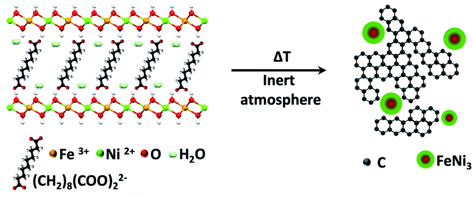 | ||
| Scheme 1 Thermal decomposition of the hybrid organic–inorganic NiFe-LDH-Seb under an inert atmosphere results in the formation of a nanocomposite consisting of FeNi3 nanoparticles and a carbon matrix. | ||
It was assumed that the periodic distribution of catalytic centres at the atomic scale inherent to LDH layers and the intimate contact between these layers and the carbon precursors in a constricted medium might explain the appearance of carbon nanoforms and reduced metal NPs. However, no direct experimental evidence of the catalytic process has been reported so far. Moreover, the issue about whether the metal reduction and the carbon graphitisation processes are concomitant or not remains an open question. Indeed, when using hexagonal NiFe-LDHs – synthesized by using ammonia releasing reagents10 and acting as catalysts in a chemical vapor deposition process (CVD), using ethylene as a carbon source – a mixture of platelets consisting of NiFe2O4, NiO and FeNi3 phases and carbon nanotubes is obtained.11 This is in contrast to the formation of metallic NPs embedded in a graphitic matrix. Thus, current experimental evidence prevents understanding the catalytic process, and therefore an in situ experimental investigation using complementary techniques sensitive to both chemistry and structure would be strongly required to shed light on this interesting process. To tackle this challenge, we thoroughly analysed the formation of the NCs by temperature-dependent powder X-ray diffraction, temperature-dependent statistical Raman spectroscopy, thermogravimetry coupled to mass spectrometry FT-IR, XPS, and last but not least, using real-space techniques such as in situ temperature-dependent atomic-resolution aberration-corrected scanning transmission electron microscopy (STEM) and electron energy-loss spectroscopy (EELS) at 80 kV.
Altogether we have been able to observe when and how different changes occur, seeing the structural conversion and the formation of metallic NPs embedded in a graphitic matrix at very low calcination temperatures. The formation of FeNi3 NPs starts between 200 and 250 °C, and the concomitant collapse of the layered structure and the formation of the carbon nanoforms occur in the range 350–450 °C.
Results and discussion
The precursor used in this work is a NiFe-LDH with sebacate molecules in the interlayer space (NiFe-LDH-Seb) and an experimental Ni![[thin space (1/6-em)]](https://www.rsc.org/images/entities/char_2009.gif) :Fe ratio of 3:1, synthesized by a coprecipitation method under controlled heating conditions at 80 °C for 4 days, following a previously reported procedure.6,12
:Fe ratio of 3:1, synthesized by a coprecipitation method under controlled heating conditions at 80 °C for 4 days, following a previously reported procedure.6,12
In order to evaluate the formation of the NC, we have monitored the change in the crystallinity of the initial NiFe-LDH-Seb by in situ X-ray powder diffraction (XRPD) as a function of the temperature under a nitrogen atmosphere. Fig. 1a shows the evolution of the XRD patterns of the NiFe-LDH-Seb sample starting from room temperature until reaching 500 °C. The XRPD pattern measured at room temperature displays broad and small diffraction lines confirming the presence of the NiFe-LDH phase forming very small crystalline domains. The peaks at 2θ = 11.14° and 18.96° can be assigned to the reflections (006) and (009) and provide information about the c parameter of the unit cell, which is related to the interlayer distance. An additional broad signal at higher angles, close to 2θ = 60°, is assigned to the reflection (110) and can provide information on the a parameter of the unit cell, related to the minimal distance between the cations within the layer. So, values of a and the basal spacing (c/3) were calculated to be 3.07 Å and 15.9 Å, respectively, in good agreement with values determined in a previous report.5
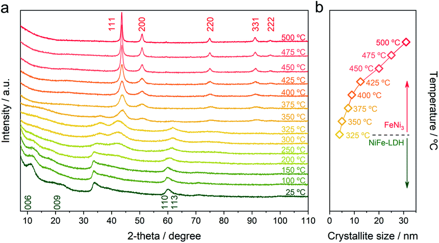 | ||
| Fig. 1 (a) In situ XRPD patterns of the NiFe-LDH-Seb sample as a function of the temperature. The measurements were carried out in a heating chamber under a nitrogen atmosphere. (b) Crystallite size calculated using the Scherrer equation applied to the diffraction peak corresponding to the (111) plane (eqn (1)). | ||
The evolution of the XRPD patterns suggests that the LDH structure remains unchanged until 200 °C indicating that the basal space of the sample was not significantly affected by the removal of interlamellar water molecules (vide infra), which generally occurs in this range of temperatures. This means that in our sample, the double anchoring point of sebacate anions imposes the interlayer distance, in contrast to other LDH hybrids endowed with interlamellar anions connected by only one anchoring point, in which heating induces remarkable changes in the basal spacing.13
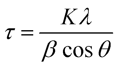
As soon the temperature reaches 250 °C, the reflection lines from the LDH structure are progressively becoming smaller and broader, suggesting its collapse and consumption. Meanwhile, a new peak starts to emerge at around 2θ = 42.5°, which can be assigned to the (111) reflection coming from a fcc structure, ascribed to the NiFe metallic alloy. Next, a drastic structural transformation takes place between 250 and 350 °C, as new diffraction lines start to appear while the ones corresponding to the LDH phase start to vanish, suggesting the massive transformation of the crystalline LDH phase into a new one. These peaks observed at 2θ = 50.87°, 75.45° and 91.05° are indexed to the (200), (220) and (331) reflections, respectively, and are characteristic of the fcc structure of the FeNi3 alloy (JCPDS No. 38–0419).14,15 Up to 375 °C the reflections from the fcc structure of FeNi3 become narrower and more intense, indicative of an enhancement in the crystallinity as well as a growth in the crystallite size. In fact, the growth of crystallite size can be estimated employing the Scherrer equation (eqn (1)):
 | (1) |
Average FT-IR spectra (of at least 10 single point spectrum) of the NiFe-Seb-LDH sample were carried out ex situ after each heat treatment at different temperatures in a CVD oven under an inert nitrogen atmosphere (Fig. SI 2†). The measurements depict at least two steps in the transformation of NiFe-LDH Seb into the NC. In the 25–200 °C range the loss of interlayer water can be clearly followed by a decrease in the broad band at around 3400 cm−1, which corresponds to O–H stretching modes of water molecules, vanishing completely at 300 °C. Additionally, the collapse of the LDH structure and its transformation into metallic NPs are distinctly evidenced by the marked disappearance of the metal–oxygen (M–O) stretching and bending modes (600 cm−1)16 in the 200–300 °C, in good agreement with the above-discussed XRPD data. Finally, the diminution of asymmetric/symmetric stretching modes attributed to C–O confirms the loss of RCOO− groups.
In order to gain more information about the thermal behavior of the NiFe-LDH-Seb sample and the corresponding chemical changes, thermogravimetric analysis coupled to mass spectrometry (TG-MS) measurements were carried out.17Fig. 2a shows the mass loss of the sample upon heating up to 500 °C, which consists of a two-stage process: a first mass loss of 5% below 170 °C attributed to the loss of interlamellar and surface adsorbed water molecules (m/z = 18) and a second mass loss of ca. 30% from 220 to 400 °C (attributed to dehydroxylation and decomposition/pyrolysis of the sebacate anion).16,17 The second mass loss indicates that the organic anion decomposes in a relatively well-defined manner (step) and releases fragments that correspond to formaldehyde (m/z = 30) and CO2 (m/z = 44). The release of formaldehyde, peaking at around 250 °C, is explained by the reduction of the carboxyl group of the sebacate anion. Afterwards, the emission of formaldehyde decreases as a result of the beginning of the dehydroxylation process, which is indicated by the emission of water molecules, and subsequently CO2 is being released instead. Further heating to nearly 350 °C marks a steep mass loss accompanied by an abrupt increase in the emission of H2O and CO2 as well as a fragment corresponding to benzene (m/z = 78). The production of the latter hints towards a catalytic process involving Ni and/or Fe metal centers which are by now (at 350 °C) reduced to their metallic form as indicated by the XRPD and FT-IR data discussed above.18 Raman spectroscopy has been also used to further understand the evolution of the organic molecules as a function of temperature under a N2 atmosphere (Fig. 2b).19 The mean spectra of the pristine NiFe-LDH-Seb at room temperature measured using a laser with a 532 nm excitation wavelength display large features in the 2750–2950 cm−1 region ascribed to asymmetric and symmetric stretching of the C–H bond, whilst the bands in the 750–1750 cm−1 region are attributed to the deformation and twisting of the CH2 within the alkyl chain of the sebacate molecules.20 The characteristic peaks of M–O species are detected at 622 and 671 cm−1, though the intensity of the signals is quite low. Upon heating, no significant changes can be observed up to 200 °C; then the intensity of the CH2 signals starts to decrease (in concordance with FTIR), while at the same time new bands at 1354 and 1581 cm−1 characteristic of a graphitic material rise (i.e., D and G), indicating the conversion of the organic chains from sebacate molecules into a new graphitic structure. The D and G bands become more evident as we continue heating up to 350 °C. This observation fits perfectly well with the benzene signal detected by TG-MS and sheds light into the chemical transformation that takes place within the interlamellar gallery of the NiFe-LDH-Seb. Furthermore, we correlated these results with X-ray photoelectron spectroscopy in order to analyse the oxidation state of the different components in the surface of the material. Along this front, XPS confirms the formation of graphitic carbon at 400 °C (Fig. 2c). Moreover, XPS allows corroboration of the appearance of metallic iron at 300 °C, in concordance with the in situ XRPD; however, the presence of metallic nickel, highlighted by the signal centered at 852.7 eV, is only appreciable when the temperature reaches 400 °C. It is to be noted that as a result of the configuration of the Raman chamber not being completely airproof, trace amounts of oxygen penetrated inside and caused the thermal transformations to occur at temperatures lower than those in the case of XRD, FTIR and XPS measurements, as well as inducing some combustion of the organic molecules thus making it challenging to perform confident measurements at temperatures higher than 400 °C.
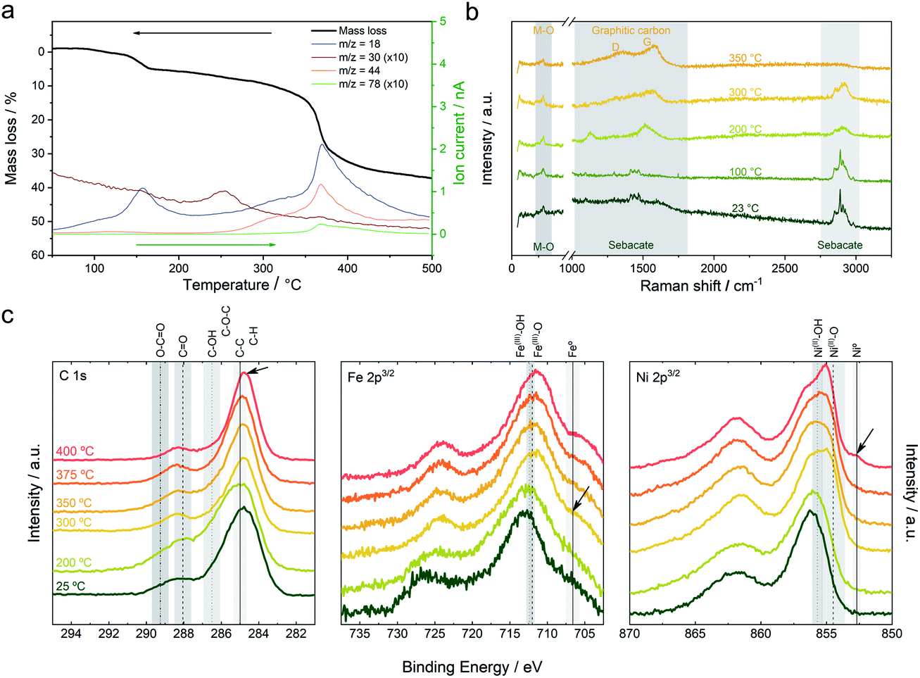 | ||
| Fig. 2 (a) TG-MS analysis using a heating rate of 10 °C min−1 under helium. (b) In situ Raman spectroscopic characterization in a heating chamber under an inert atmosphere. (c) XPS high-resolution spectra of the C 1s, Fe 2p3/2 and Ni 2p3/2 of the pristine material and the ex situ calcined samples at different temperatures. | ||
To sum up, XRPD, FT-IR, TG-MS, Raman and XPS characterization experiments confirm that heat treatment of the NiFe-LDH-Seb under an inert atmosphere results in a collapse and shrinkage of the inorganic layered structure and growth of graphitic carbon in the confined space between the layers. While the exact mechanism is still unknown, it is quite evident that it involves a concomitant decomposition of the organic anions and further catalytic graphitization of the carbon matrix, resulting in the in situ carbothermal reduction of Ni2+ and Fe3+ species, which forms FeNi3 NPs. The previous results suggest that the formation of catalytic amounts of FeNi3 NPs starts before the collapse of the layered structure (around 250–350 °C) leading to the formation of the FeNi3-carbon NC; however, we do not count with any direct experimental evidence. This process can be similar to what happens during the CVD synthesis of carbon nanotubes using carbon feedstock, where metal catalyst particles play two key roles, namely: (i) decomposition of the carbon feedstock (hydrocarbon) and (ii) catalytic nucleation/growth of the emerging nanotube. In a similar way, another study has reported the formation of graphitic nanostructures via metal-induced catalyzed graphitization using nickel, cobalt, or iron.21
In order to further clarify the formation of the NC, the precise moment when the layered structure collapses, and to determine the involved dynamic processes, we performed in situ electron microscopy analysis at temperatures ranging between room temperature and 400 °C. Specifically, we analyzed the NiFe-LDH by real-space techniques, sensitive to both structure and chemical composition, namely atomic-resolution aberration-corrected scanning transmission electron microscopy (STEM) and electron energy-loss spectroscopy (EELS) at 80 kV. For this acceleration voltage, the magnetic field within the objective lens pole piece is slightly above one Tesla.
Simultaneously, acquired low magnification annular bright field (ABF) and high angle annular bright field (HAADF) images of the as-prepared NiFe-LDH sample (Fig. SI 3 and 4†) show a flake-like structure consisting of partially curved plates with rough edges with lateral length in the tens of nanometers range, typical of LDH materials prepared by a coprecipitation method.5,6 High-resolution images in Fig. SI 5† depict the local crystallinity within the material with the expected in-plane hexagonal crystal symmetry. Compositional maps obtained from EELS measurements reveal the chemical composition of the flake and show a rather even lateral distribution of the constituent metals, namely Fe and Ni, as well as C and O.
Next, the sample was submitted to a gradual increase in temperature while, at the same time, acquiring ABF and HAADF images in situ. Fig. 3 shows the gradual morphological and structural transformation of the material as a function of temperature. After heating the sample to 300 °C, noticeable structural changes take place, such as the beginning of the formation of small particles (e.g. see the top-left of the flake) as well as the appearance of some degree of crystallization within the thinnest areas at the edges.
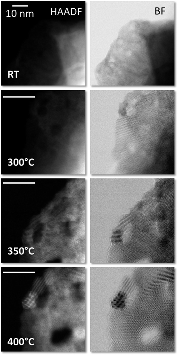 | ||
| Fig. 3 Simultaneously acquired high-angle annular dark field (HAADF, left column) and annular bright field (ABF, right column) images at high magnification, showing the evolution of the material at different temperatures. The scale bars represent 10 nm. | ||
When the temperature is increased to 350 °C, differentiation between the nanometric clusters starts to be more obvious and the degree of crystallinity of the surrounding matrix is further enhanced, in a relatively slow fashion. Nanocrystals with clearly defined shapes and sizes in the few nm ranges are visible, while holding the temperature constant for a few minutes does not result in noticeable changes (see Fig. SI 6†). Further increase in temperature, over 350 °C all the way up to 400 °C, accelerates the process, and clear effects are observed including an improvement of the crystallinity of both the FeNi3 NPs and the carbon matrix, as also seen in the high magnification images shown in Fig. 3. This is in concordance with XRD measurements.
EELS compositional maps obtained from the analysis of the C K, O K, Fe L2,3 and Ni L2,3 edges demonstrate that the metals are homogeneously distributed in the initial LDH structure (Fig. SI 7†). Interestingly, we observe the formation of totally segregated NPs of several tens of nanometers when the temperature changes from RT to 400 °C and the sample is measured in situ. Thus at 400 °C a significant oxidation of Fe, accompanied by a segregation of the FeNi3 NPs into smaller ones of nickel and iron oxide, takes place (see Fig. SI 8† for a qualitative analysis of the fine structure of the 3d metal L2,3 edges). In the present case, the magnetic field produced by the lens inside the microscope seems to be responsible for this phenomenon. As expected, this effect, which involves a redox process and a segregation of the NPs, is irreversible and therefore when the sample is brought back to room temperature, the segregated structure is retained (Fig. SI 9†) (Fig. 4).
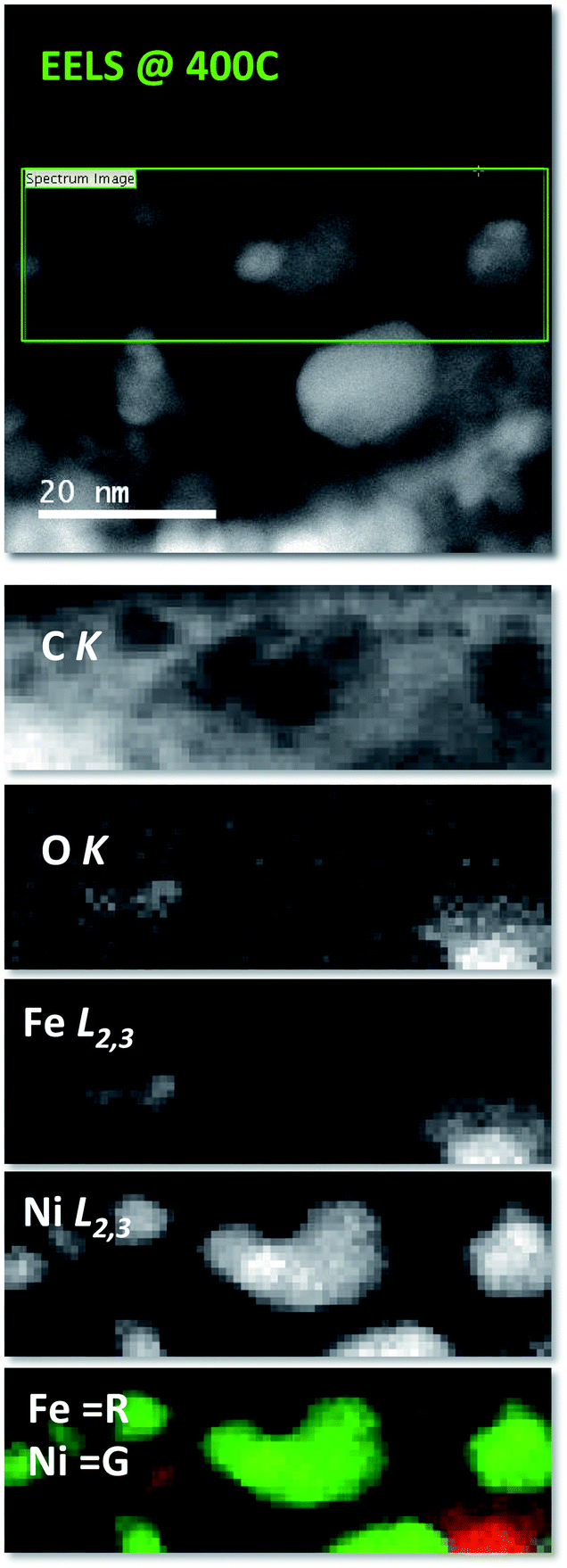 | ||
| Fig. 4 Electron energy-loss compositional maps at 400 °C at low magnifications showing the distribution of C, O, Fe and Ni. The top panel shows the HAADF image of the areas where the EEL spectrum images where measured (marked with a green rectangle), while the panels below exhibit the actual C K, O K, Fe L2,3 and Ni L2,3 images. The bottom panel shows an overlay of the Fe (red) and Ni (green) images, showing the complete segregation of both species. | ||
Compared to the previous results, a similar effect has been previously described for these NCs synthesized ex situ at 900 °C. Specifically, the segregation was observed both (i) when the NCs were employed as electrodes in supercapacitive devices working with KOH 6 M as the electrolyte, and submitted to charge and discharge cycles in the presence of an external magnetic field of 4000 G, and (ii) when heated in situ in the microscope at 400 °C for 15 hours under the magnetic field of the microscope objective lens.9
In contrast, if the sample is heated ex situ and measured afterwards in the microscope, no segregation at all should be expected.5,9 As a matter of fact, we prepared a control experiment by heating the sample from room temperature to 900 °C, showing the absence of any kind of phase segregation (Fig. 5). These results confirm that the magnetic field-induced segregation process can take place even starting from the NiFe-LDH precursor.
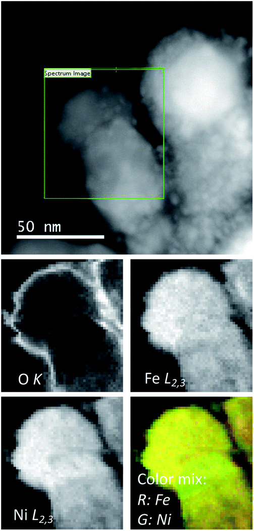 | ||
| Fig. 5 (Top) HAADF image of a NiFe-LDH-Seb sample after heating (ex situ) in the absence of the magnetic field. NPs with sizes in the tens of nm range are observed. (Bottom) EELS maps showing the O, Fe and Ni maps obtained from EEL spectrum imaging along with a color overlay of the Fe (red) and Ni (green) maps. | ||
Conclusions
With an unprecedented sum of complementary in situ techniques we have been able to observe the subtleties regarding the thermal transformation of NiFe layered double hydroxides intercalated with sebacate molecules (NiFe-LDH-Seb) into NiFe-carbon nanocomposites. A scheme summarizing the main steps involved is shown in Fig. 6. All the different techniques support that the formation of small catalytically active FeNi3 clusters precedes the collapse of the starting NiFe-LDH-Seb laminar structure. This process takes place in the range between 350 and 400 °C, driving the growth of FeNi3 metal NPs by calcination. Remarkably, these temperatures are much lower than those required in the conventional synthetic approaches used to form this metallic alloy.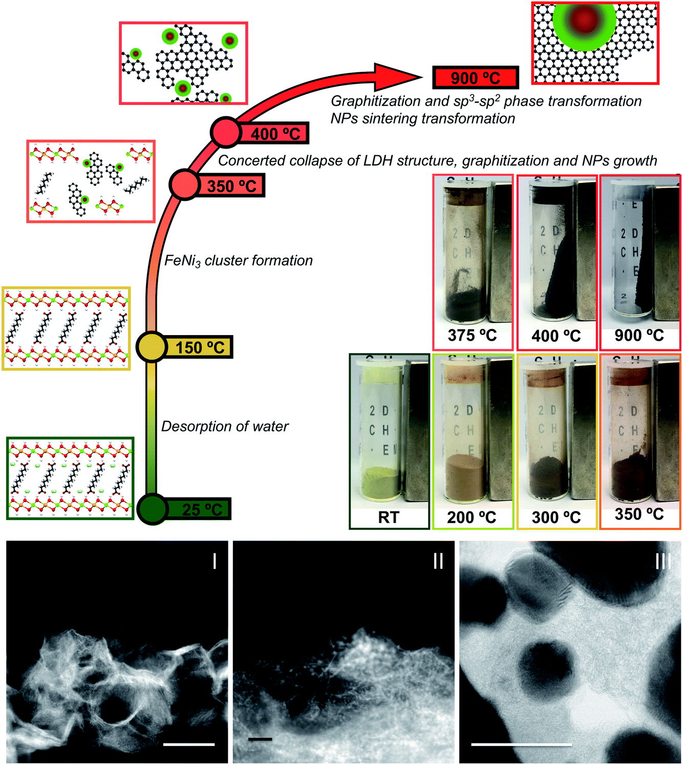 | ||
| Fig. 6 (Top) Schematic representation of the NiFe-carbon NC formation showing the principal steps. Upon heating the NiFe-LDH-Seb sample, as soon the temperature increases to 150 °C the loss of the interlayer water molecules takes place, followed by the formation of small FeNi3 clusters as a result of the reduction of NiII–FeIII until 350 °C. Afterwards, between 350° and 400 °C, the concerted collapse of the LDH structure with the graphitization of the sebacate molecules and a growth of the NiFe NPs occurs. For higher temperatures, a progressive graphitization of the carbon matrix and sp3–sp2 phase transformation occur simultaneously with a sintering process that increases the metallic NPs' size. (Bottom) From left to right, HAADF images showing the evolution from pristine NiFe-LDH-Sebacate measured at room temperature (I), to the formation of small metallic clusters (II) before the layered structure collapse, leading to the final formation of the NiFe-carbon NC (III, ABF image). Scale bars represent 50 nm. | ||
These results provide a better understanding on the intriguing formation of carbon-based NCs employing layered hydroxides as precursors, providing tools for tuning their properties for different applications of interest. In this sense, in situ temperature-dependent experiments in the presence of the intrinsic magnetic field of a scanning transmission electron microscope have allowed observation of the complete metal segregation of Ni and Fe even at 400 °C. This result has shown to be very important to understand the formation of highly electrochemically active NiFe-carbon NCs.9
Experimental
Chemicals
All chemical reagents Ni(NO3)2·6H2O, Fe(NO3)3·9H2O, HO2C(CH2)8CO2H (sebacic acid), NaOH, and ethanol (Aldrich, Fluka, Alfa-Aesar) were used as received without further purification. Ultrapure water was obtained from Millipore Milli-Q equipment.Synthesis of the NiFe-LDH-Seb
The precursor NiFe-LDH-Seb was prepared following the general method described previously by our group, using sebacic acid/NaOH.6,12Physical characterization
The metallic atomic composition of bulk samples was determined by means of electron probe microanalysis performed in a Philips SEM-XL30 equipped with an EDAX microprobe. Carbon, nitrogen, and hydrogen contents were determined by microanalytical procedures by using a LECO CHNS-932. X-ray powder diffraction (XRPD) patterns were obtained with a Malvern Panalytical Empyrean diffractometer using copper Kα radiation (Cu-Kα = 1.54178 Å). Attenuated total reflectance Fourier-transform infrared (ATR-FT-IR) spectra were collected in an Agilent Cary 630 FTIR spectrometer in the 4000–650 cm−1 range in the absence of KBr pellets. X-ray photoelectron spectroscopy (XPS) measurements were performed on a Thermo Scientific™ K-Alpha™ X-ray photoelectron spectrometer. Al Kalpha X-ray radiation was employed as the X-ray source. For all the elements more than 100 spectra were recorded employing a step of 0.1 eV with a focused spot higher than 50 μm. XPS data were analyzed with Thermo Avantage v5.9912 software. Raman spectroscopic characterization was carried out on a Horiba LabRAM Aramis confocal Raman microscope (λexc = 532 nm) with a laser spot size of ca. 1 μm (Olympus LMPlanFl 100, NA 0.80). The incident laser power was kept as low as possible to avoid structural sample damage: 0.17–1.8 mW. Spectra were obtained with a CCD array at −70 °C, grating: 600 grooves per mm. Spectra were obtained from a 20 × 20 μm area with 1 μm step size. Sample movement was carried out using an automated XY-scanning table. STEM-EELS observations were carried out in a JEOL ARM200cF equipped with a spherical aberration corrector, a cold field emission gun and a Gatan Quantum EEL spectrometer, operated at 80 and 200 kV. The intensity of the magnetic field within the objective lens pole piece gap is of the order of 1 T. In situ heating experiments were carried out using a DENS solutions Lighting D9 double tilt holder. EELS compositional maps were obtained by fitting EEL spectrum images to reference spectra via multiple linear least square (MLLS) fits.Conflicts of interest
The authors declare no competing financial interest.Acknowledgements
Financial support from the European Union (ERC Advanced Grant Mol-2D 788222, ERC Starting Grant 2D-PnictoChem 804110, ERC Proof of Concept Grant Hy-MAC 713704, and COST-Action on Molecular Spintronics (MOLSPIN CA15128)), the Spanish MINECO (Projects MAT2017-89993-R, MAT2015-66888-C3-3-R, RTI2018-097895-B-C43 co-financed by FEDER, and the Unit of Excellence “Maria de Maeztu” MDM-2015-0538), and the Generalitat Valenciana (Prometeo Program and iDiFEDER/2018/061 co-financed by FEDER) is gratefully acknowledged. G. A. acknowledges the support by the Deutsche Forschungsgemeinschaft DFG (FLAG-ERA AB694/2-1) and the Generalitat Valenciana (CIDEGENT/2018/001 grant). G. A. received financial support through the Postdoctoral Junior Leader Fellowship Programme from “la Caixa” Banking Foundation. J. R. thanks the Spanish MINECO for his predoctoral grant. Electron microscopy observations were carried out at the ICTS ELECMI node at Centro Nacional de Microscopía Electrónica at the Universidad Complutense de Madrid. The authors thank Dr María Dolores Jordán Martín for her kind assistance with the XPS measurements.Notes and references
- N. S. Lewis and D. G. Nocera, Proc. Natl. Acad. Sci. U. S. A., 2006, 103, 15729–15735 CrossRef CAS PubMed.
- H. B. Gray, Nat. Chem., 2009, 1, 7 CrossRef CAS PubMed.
- F. Bonaccorso, L. Colombo, G. Yu, M. Stoller, V. Tozzini, A. C. Ferrari, R. S. Ruoff and V. Pellegrini, Science, 2015, 347, 1246501 CrossRef PubMed.
- G. Abellán, A. Ribera, E. Coronado, WO2013-124503-A1, 2013.
- G. Abellán, E. Coronado, C. Martí-Gastaldo, A. Ribera and T. F. Otero, Part. Part. Syst. Charact., 2013, 30, 853–863 Search PubMed.
- G. Abellán, E. Coronado, C. Martí-Gastaldo, A. Ribera and J. F. Sánchez-Royo, Chem. Sci., 2012, 3, 1481–1485 RSC.
- G. Abellán, J. G. Martínez, T. F. Otero, A. Ribera and E. Coronado, Electrochem. Commun., 2014, 39, 15–18 CrossRef.
- G. Abellán, C. Martí-Gastaldo, A. Ribera and E. Coronado, Acc. Chem. Res., 2015, 48, 1601–1611 CrossRef PubMed.
- J. Romero, H. Prima-Garcia, M. Varela, S. G. Miralles, V. Oestreicher, G. Abellán and E. Coronado, Adv. Mater., 2019, 31, 1900189 CrossRef PubMed.
- G. Abellán, E. Coronado, C. Martí-Gastaldo, E. Pinilla-Cienfuegos and A. Ribera, J. Mater. Chem., 2010, 20, 7451–7455 RSC.
- G. Abellán, J. A. Carrasco, E. Coronado, J. P. Prieto-Ruiz and H. Prima-García, Adv. Mater. Interfaces, 2014, 1, 1400184 CrossRef.
- E. Coronado, J. R. Galán-Mascarós, C. Martí-Gastaldo, A. Ribera, E. Palacios, M. Castro and R. Burriel, Inorg. Chem., 2008, 47, 9103–9110 CrossRef CAS PubMed.
- G. Abellán, J. Luis Jordá, P. Atienzar, M. Varela, M. Jaafar, J. Gómez-Herrero, F. Zamora, A. Ribera, H. García and E. Coronado, Chem. Sci., 2015, 6, 1949–1958 RSC.
- X. Lu, G. Liang and Y. Zhang, J. Mater. Sci. Eng. B, 2007, 139, 124–127 CrossRef CAS.
- X. G. Liu, B. Li, D. Y. Geng, W. B. Cui, F. Yang, Z. G. Xie, D. J. Kang and Z. D. Zhang, Carbon, 2009, 47, 470–474 CrossRef CAS.
- J. A. Carrasco, J. Romero, M. Varela, F. Hauke, G. Abellán, A. Hirsch and E. Coronado, Inorg. Chem. Front., 2016, 3, 478–487 RSC.
- E. Conterosito, L. Palin, D. Antonioli, D. Viterbo, E. Mugnaioli, U. Kolb, L. Perioli, M. Milanesio and V. Gianotti, Chem.–Eur. J., 2015, 21, 14975–14986 CrossRef CAS PubMed.
- R. Anton, Carbon, 2009, 47, 856–865 CrossRef CAS.
- G. Abellán, M. Schirowski, K. F. Edelthalhammer, M. Fickert, K. Werbach, H. Peterlik, F. Hauke and A. Hirsch, J. Am. Chem. Soc., 2017, 139, 5175–5182 CrossRef PubMed.
- M. R. Islam, Z. Guo, D. Rutman and T. J. Benson, RSC Adv., 2013, 3, 24247–24255 RSC.
- J. Hoekstra, A. M. Beale, F. Soulimani, M. Versluijs-Helder, J. W. Geus and L. W. Jenneskens, J. Phys. Chem. C, 2015, 119, 10653–10661 CrossRef CAS.
Footnote |
| † Electronic supplementary information (ESI) available. See DOI: 10.1039/d0sc00697a |
| This journal is © The Royal Society of Chemistry 2020 |