
 Open Access Article
 This Open Access Article is licensed under a Creative Commons Attribution-Non Commercial 3.0 Unported Licence
Improvement of Cs detection performance and formation of CsCl and Cs nanoparticles by tuning graphene oxide quantum dot-based nanocomposite†
Bangun Satrio Nugroho ab and
Satoru Nakashima*abc
ab and
Satoru Nakashima*abc
aRadioactivity Environmental Protection Course, Phoenix Leader Education Program, Hiroshima University, 1-1-1 Kagamiyama, Higashi-Hiroshima 739-8524, Japan. E-mail: snaka@hiroshima-u.ac.jp
bDepartment of Chemistry, Graduate School of Science, Hiroshima University, 1-3-1 Kagamiyama, Higashi-Hiroshima 739-8526, Japan
cNatural Science Center for Basic Research and Development, Hiroshima University, 1-4-2 Kagamiyama, Higashi-Hiroshima 739-8526, Japan
First published on 6th July 2022
Abstract
A new nanocomposite was developed using functionalized graphene oxide quantum dots (GOQDs) with cesium green molecules for the first time. Although the cesium green molecule works effectively only in the solid-state, without water, and in basic conditions, the functionalized GOQDs with cesium green made the nanocomposite work well as a cesium (Cs) detector in mixed solution (distilled water/THF). The nanocomposite can be employed as a Cs detector in both acidic and basic conditions. The present study revealed that the nanocomposite of GOQDs with cesium green showed an enhanced photoluminescence in basic conditions, while the intensity of the photoluminescence in acidic conditions is the superposition of the photoluminescence of the corresponding components. The photoluminescence of the nanocomposite was quenched (turned OFF) after Cs treatment in basic conditions. On the other hand, in the acidic conditions it was found that the photoluminescence intensity of this nanocomposite was enhanced (turned ON) by the Cs addition in two different Cs concentrations, 0.06 mmol L−1 and 0.12 mmol L−1. In addition, the movement of the nanocomposite (after Cs addition) under the electron beams through TEM measurement was observed. The formation of CsCl and Cs nanoparticles was identified. Specifically, the Cs cluster occurrence is discussed by taking into account the mobility effect of the adatoms on the composite layer under electron beam irradiation.
1 Introduction
The Fukushima Dai-ichi Nuclear Power Plant (FDNPP) disaster that occurred in 2011 attracted the attention of researchers. Specifically, the release of radioactive materials like Cs-137 (with a half-life of 30.1 years) has drawn attention because of the immediate and long-term effects on the environment.1,2 Since radioactive cesium (Cs) has a high solubility in water and a long half-life, it can migrate from one pond to the river, move far away to the paddy fields,3 and finally come into the groundwater. As reported in the previous work, radioactive Cs was detected in the tap water and ground water with different degrees of contamination in some areas of Fukushima.4 Consequently, its consumption by all people who stay around the FDNPP area was restricted. Therefore, the detection of Cs is of great importance to address the problem of Cs contamination in water.Currently, several types of methods for Cs detection exist including atomic absorption spectroscopy, electrochemical devices, germanium detector, inductively coupled plasma mass spectroscopy, and fluorescence-based method. Especially the fluorescence-based method, which is infrequently used in Cs detection system, has a potential to become a non-destructive detector with low-cost. In the previous study squaraine dye as a mixed solution (DMSO/Water) exhibited a good response in Cs detection. This compound can work effectively and selectively by quenching the fluorescence intensity after Cs detection. According to this method, the blue fluorescence of the compound solution turned OFF after the Cs addition.5 In the other work, T. Mori et al. have successfully designed a new supramolecular material (cesium green, C32H33NO8) as Cs sensor expecting intermolecular fluorescence approaches (fluorescence resonance energy transfer (FRET) or exciplex mechanism).6 The study of energy transfer has been reported experimentally for different kinds of nanomaterials (quantum dots, nanoparticles) that act as energy donors or acceptors.7,8 Another researcher also demonstrated that the Cs can be detected using green fluorescence by cesium green (in methanolic solution) for the freeze-dried stem of plants that have already been treated with cesium carbonate.9 However, the cesium green molecule has several limitations in Cs detection application, since it can work effectively only in solid-state, without water, and in basic condition. Therefore, several technical problems should be addressed to make it more useful and easily to be used in order to identify Cs in contaminated water.
In recent years, graphene oxide (GO) and graphene oxide quantum dots (GOQDs) are widely studied in several applications such as metal adsorbent (Cs+, Eu3+, Sr2+),10,11 and designed as fluorescence probes by considering their quantum confinement and the edge effect.12,13 In addition, the GO and GOQDs have almost similar properties because they have various oxygen functional groups. The functional group can act as a binding point to synthesize a new nanocomposite to improve their properties.14,15 Another important thing is that the photoluminescence (PL) of GOQDs was independent of pH. It means that the emission wavelength does not shift in different pH condition (only change in the PL intensity).16 Further investigation also revealed that the PL of GO has shown a reversible response to ionic strength and pH.17,18 The previous work confirmed that the different number of layers of GO (single and a few layers) showed different optical responses in various organic solvent.19 More currently, Yao et al. have employed graphene quantum dot-based fluorescence sensing as a dual detector of copper ion (Cu2+) and tiopronin (MPG). They proposed a novel fluorescence turn OFF for the Cu2+ detection and turn ON for the tiopronin (MPG) detection.20
Therefore, to facilitate the development of a Cs detection system, it is highly desirable to create a new nanocomposite using functionalized graphene oxide quantum dots (GOQDs) with cesium green molecule. The main purpose of the present study is to produce a new nanocomposite that has the ability to recognize Cs in water with different pH conditions (acidic and basic condition) by considering the turn ON/OFF response.
2 Experimental section
2.1. Reagents and materials
Graphite, cesium green (C32H33NO8), potassium permanganate (KMnO4), hydrogen peroxide (H2O2), sulfuric acid (H2SO4), sodium nitrate (NaNO3), sodium hydroxide (NaOH), cesium chloride (CsCl), hydrochloric acid (HCl), and potassium hydroxide (KOH) were analytical grade and were used without any further purification.2.2. Synthesis of GO and GOQDs
Graphene oxide (GO) samples were prepared using modified Hummer's method with graphite and the oxidizing agent, KMnO4 (1![[thin space (1/6-em)]](https://www.rsc.org/images/entities/char_2009.gif) :4, mass ratio).21 In this synthesis protocol, pre-cooling procedure and one minute stop-one minute go was implemented when adding the KMnO4 according to our work.10 The GOQDs were synthesized by using as-prepared few-layers GO. In a typical synthesis, the ratio of GO and NaOH was 1:1 (mass ratio). First, dispersed the starting material GO (0.19 g) into distilled water followed by sonification for 5 minutes. Then, added NaOH (0.19 g) and stirred for 5 minutes at ambient temperature. Second, the solution was refluxed at 80 °C for two hours. After finished the reflux process, kept the solution at room temperature for a while. Then, came to the final step, centrifuged the solution for two times (4000 rpm for 10 minutes and 9500 g-force (relative centrifuge force) for 50 minutes). The brown solution was obtained as GOQDs solution. There is no further treatment for as-obtained GOQDs solution (Fig. 2e).
:4, mass ratio).21 In this synthesis protocol, pre-cooling procedure and one minute stop-one minute go was implemented when adding the KMnO4 according to our work.10 The GOQDs were synthesized by using as-prepared few-layers GO. In a typical synthesis, the ratio of GO and NaOH was 1:1 (mass ratio). First, dispersed the starting material GO (0.19 g) into distilled water followed by sonification for 5 minutes. Then, added NaOH (0.19 g) and stirred for 5 minutes at ambient temperature. Second, the solution was refluxed at 80 °C for two hours. After finished the reflux process, kept the solution at room temperature for a while. Then, came to the final step, centrifuged the solution for two times (4000 rpm for 10 minutes and 9500 g-force (relative centrifuge force) for 50 minutes). The brown solution was obtained as GOQDs solution. There is no further treatment for as-obtained GOQDs solution (Fig. 2e).
2.3. Synthesis of GOQD-based nanocomposite
The nanocomposite was generated by combining GOQDs solution as precursor material with cesium green (CG) solution. In this study, the nanocomposite was produced in two different concentration ratios of GOQDs:Cesium green (concentration ratio 5:1 and 8:1). In order to obtain the nanocomposite with a concentration ratio of 5:1, first, prepare 25 mL GOQDs solution (distilled water) and prepare the cesium green solution by dissolving 1 mg cesium green in 5 mL THF solvent. After that, mixed the GOQDs solution with cesium green solution followed by stirring for 30 minutes. A similar treatment was performed for the nanocomposite with a concentration ratio of 8:1. In order to distinguish both nanocomposites, the term composite-51 and composite-81 were applied. Each index number attached to the composite name is corresponded to the concentration ratio of GOQDs:cesium green molecule.
2.4. Photoluminescence detection of cesium
The Cs detection was performed at room temperature. There are two different concentrations of cesium chloride (CsCl) solution. The CsCl solution was made by adding 0.6 g CsCl in 30 mL distilled water. Based on that, the concentration of the CsCl solution was 0.12 mmol L−1. Then, prepared the second CsCl solution to get a concentration of 0.06 mmol L−1. The next step was that the different amounts of CsCl solution (changing volume from 200 μL-800 μL) were added into the nanocomposite solution. The photoluminescence spectra were measured and recorded under excitation slit 10 nm, emission slit 10 nm, PMT voltage 400 V, and excitation wavelength 330 nm. Finally, plotted the data as a standard curve graph (the PL intensity unit is cps as measured from the instrument).2.5. Instrumentation and characterization
Atomic force microscopy (AFM) was conducted by Asylum, MFP-3D origin (Oxford, UK). Ultraviolet-visible spectroscopy (UV-Vis) measurements were carried out using JASCO V-650 spectrophotometer (Japan). Photoluminescence spectroscopy measurement was performed by Fluorescence spectrophotometer F-7000, Hitachi (Fukuoka, Japan). Transmission electron microscopy (ultra-high resolution transmission electron microscope) was performed using JEM-2010 (Tokyo, Japan). Zeta potential measurements were performed using Zeta potential and particle size analyser ELSZ-series 2000 (Otsuka, Japan). Elemental analysis was carried out using PerkinElmer CHNS/O 2400II (USA).3 Results and discussion
3.1. Characterization of GO and GOQDs
The transmission electron microscopy (TEM) (Fig. 1a and b) and atomic force microscopy (AFM) (Fig. 1c and d) were performed to characterize the morphology and structure of GO as precursor material and GOQDs after reflux process. It is observed that the GO sample is wrinkles and overlap (Fig. 1a). For the ratio of graphite to potassium permanganate (KMnO4) as oxidizing agent, 1:4, the graphite was successfully exfoliated. The elemental analysis of the GO sample was carried out to confirm the C, H, N, and O element as displayed in the Table 1. In addition, the as obtained GO was employed as a precursor to fabricate GOQDs. As shown in Fig. 1b, the GOQDs image was produced. The NaOH reflux process has detached well the flake of oxidation debris (OD) from GO sample. These pieces (several nm) fell down on the GO layer. These are GO quantum dots (GOQDs). The GOQDs have a heterogeneous particle size distribution as is shown in TEM imaging (Fig. 1b). As proposed by previous experimental work, these small particles are adsorbed on the surface of graphene-like sheets.22 And these small particles can be separated from GO by base treatment. Rourke at al. used the terminology for this small particle as ‘oxidation debris'.23
 | ||
| Fig. 1 TEM imaging of (a) GO, scale bars: 200 nm, (b) GOQDs, scale bars: 50 nm. (c) AFM image of GO, and (d) GOQDs deposited on freshly cleaved silicon substrate. | ||
| Sample | C% | H% | N% | O% | C/O |
|---|---|---|---|---|---|
| GO | 43.82 | 2.97 | 0.18 | 52.4 | 0.84 |
Furthermore, to confirm the thickness of the GO and GOQDs sample, the AFM imaging was conducted. Fig. 1c exhibited the height of GO is about 2–3 nm. It is also convinced that the GO material consists of a few layers. In addition, there are two types of dots for as-obtained GOQDs. The aggregating dots (aggregates) and small dots were confirmed with an average thickness of about 2 nm and 1.5 nm, respectively (Fig. 1d, S1a, see ESI†). This value (for small dots) is close to the value corresponding to the thickness of OD as previously obtained by AFM (0.5–1.5 nm)24 and SNR or specular neutron reflectivity (1 nm).25 It is suggested that the aggregates are composed of many single GOQDs gathered as disc pile up (H-type aggregation) (Fig. S1b, see ESI†) rather than head to tail arrangement (J-type aggregation). Another group has reported that there is a unique emission of graphene quantum dots induced by self-assembled aggregation.26
3.2. Optical properties of GOQDs and their nanocomposite
The optical properties of GOQDs were characterized. UV-Vis absorption spectra (Fig. 2a) show a broad absorption from 800 to 200 nm and have one peak at 205 nm and two shoulders at 270 nm and 330 nm for GOQDs. The photoluminescence (PL) spectra (Fig. 2b) show that the different PL peak intensity appeared before (Fig. 2d) and after centrifugation process (Fig. 2e). This method also has been considered by another researcher to achieve the tunable optical properties.27 In particular, the centrifugation method demonstrated an effective way to decrease the size of functionalized graphene oxide (GO). This is in good accordance with the characterization data shown in an early section (Fig. 1b). The TEM image emphasized a different size of GOQDs. Moreover, in the Fig. S5a (see ESI†), the larger particle has been isolated. It showed the presence of large sheets, almost similar in size with the as-produced GO (Fig. 1a). As a result, it is expected that as-produced GOQDs have an intrinsic PL intensity. The other experimental studies were reported to identify the disintegration of GO during the base treatment.22 In their work, the concentration ratio of GO to NaOH, 1:1, was used to treat with heating for 1–5 hours. The results showed that the prolonged base treatment leads to disintegration of the flake of GO into smaller pieces. This work also confirmed that insignificant deoxygenation would proceed if base treatment was conducted without heating. On the contrary, heating without base treatment does not bring in detectable deoxygenation. It is consistent with our result that confirmed the deoxygenation after base treatment with reflux process. As is shown in Fig. S5b (see ESI†), the elemental analysis obtained by TEM shows that the oxygen content decreased significantly.
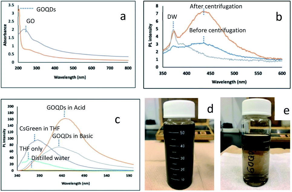 | ||
| Fig. 2 UV-Vis absorbance of (a) GO, GOQDs. Photoluminescence emission spectra of (b) GOQDs before and after centrifugation process, (c) GOQDs in acidic and basic condition, cesium green in THF. (d) GO solution after reflux process (before centrifugation). (e) GOQDs solution after centrifugation. | ||
The photoluminescence (PL) spectra of GOQDs, cesium green (CG) and their nanocomposite in THF solvent were shown in Fig. 2 and 3. The PL spectra of GOQDs are significantly different between acidic and basic conditions. As is reported by a previous study the GOQDs are strongly sensitive to the deprotonation and protonation process.28,29 It is suggested that the different concentration in OH− and H+ influences the change of electronic transition of π–π* and n–π* in GOQDs. It is also amplified by Taniguchi et al. that the proposed concept of the reversible epoxy formation leads to pH-dependent on/off PL of GO.18 They found that the enhancing and quenching PL of GO can be induced by increasing/decreasing the epoxy concentration and will be influenced by the presence of charge transfer exciton (CTE). In the present study, the PL intensity of GOQDs in acidic condition increased compared to that in basic condition. The present result may be explained by pH-dependent change of functional group. The peak also red-shifted from 435 nm to 454 nm by changing from basic to acidic condition (Fig. 2c).
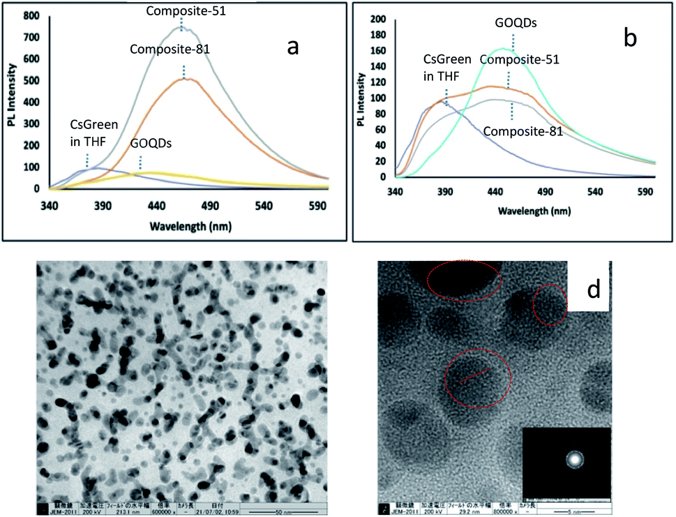 | ||
| Fig. 3 Photoluminescence emission spectra of (a)composite-51, composite-81 in basic condition, (b) composite-51, composite-81 in acidic condition. (c) TEM image of GOQDs-based nanocomposite (composite-81). Scale bars: 50 nm. (d) High-resolution TEM image of individual nanodot (composite-81) labelled by red circle with inset of the Fast Fourier Transform (FFT) from the selected region. Scale bars: 5 nm. | ||
On the other hand, as shown in Fig. 3, after the nanocomposite was formed, the PL intensity drastically increased in basic condition (pH 11.01) for both nanocomposites (composite-51 and composite-81), while the PL intensity was slightly quenched in acidic condition. In this case, the PL of the nanocomposite exhibited an opposite response for acidic and basic conditions compared with the original sample. For original sample, the GOQDs exhibited enhancing PL intensity in acidic condition and quenching PL intensity in basic condition. Whilst for the nanocomposites, the decreased PL intensity was observed in acidic condition and the increased PL intensity was observed in basic condition. In the other work the GO showed the reversible response upon acidic and basic condition.27 Fig. 3b shows that the spectrum of the nanocomposite is almost the superposition of the GOQDs and CG in acidic condition, suggesting the physical mixture of GOQDs and CG in acidic condition. On the other hand, the PL intensity of the nanocomposite was significantly enhanced under basic condition (Fig. 3a). In basic condition the chemical bond was suggested between GOQDs and CG. This enhancement in basic condition is in accordance with PL of conventional carbon nanodots with edge-located COH/COOH/C![[double bond, length as m-dash]](https://www.rsc.org/images/entities/char_e001.gif) O groups.30 In the present experiment, the pH condition was changed from basic condition to acidic condition. Then we also investigated the PL intensity of the nanocomposite from acidic condition to basic condition. As a result, the peak moved back to the original position and the intensity significantly increased (Fig. S13, see ESI†).
O groups.30 In the present experiment, the pH condition was changed from basic condition to acidic condition. Then we also investigated the PL intensity of the nanocomposite from acidic condition to basic condition. As a result, the peak moved back to the original position and the intensity significantly increased (Fig. S13, see ESI†).
As is already reported, the GOQDs-PEG (polyethylene glycol) interaction exhibited a typical excitation wavelength dependence of the photoluminescence.31,32 Fig. 3c, and S3, S4 (see ESI†) show the TEM image of the present composite. It can be seen that the nanodots are combined. Fig. 3d shows high-resolution TEM image of an individual nanodot (composite-81). This indicates high crystallinity (localized in lattice fringes labelled by red circle) of GOQDs after forming a composite. It is also suggested that the cesium green (CG) molecule functionalization of GOQDs does not cause significant damage to the graphene π system.
3.3. Cs detection performance
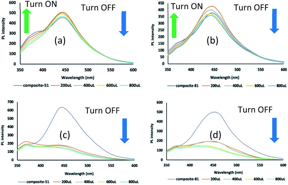
The results show that the addition of 0.12 mmol L−1 cesium chloride (200–800 μL) in acidic condition led to increase the PL intensity gradually (turn ON) by employing composite-51 (Fig. 4a). For composite-81, using similar method with the case of composite-51, the PL intensity was decreased (turn OFF) at the first time of Cs addition (200 μL), and then the PL intensity increased (turn ON) gradually after adding another 200 μL CsCl solution (Fig. 4b). The turn ON PL phenomenon also occurred in composite-81 by reducing the concentration of CsCl (0.06 mmol L−1) (Fig. 4c). This might be explained by the fact of composite-81 having much GOQDs part compared with the composite-51. At first GOQDs part reacts with CsCl, leading to the decrease in PL intensity (Fig. 4b) as is observed in GOQDs (Fig. 4d). After that, turn ON occurs as is the case of composite-51.
 | ||
| Fig. 4 Photoluminescence emission spectra of (a) composite-51 before and after Cs treatment for 0.12 mmol L−1 (in acidic condition), (b and c) composite-81 before and after Cs treatment for 0.12 mmol L−1 and 0.06 mmol L−1 (in acidic condition), (d) GOQDs after and before Cs treatment for 0.12 mmol L−1 (in acidic condition). A colour line (graphic) in each figure indicates the PL response signal by the additional amount of CsCl solution, with volume range 200 μL (orange), 400 μL (gray), 600 μL (yellow), and 800 μL (blue). | ||
We also considered that another factor such as structural defect (holes) effect might contribute to the PL phenomenon. The presence of holes in nm-size was investigated in HRTEM studies of GO.33 Another researcher also considered these tiny vacancy defect as a part of the oxidized domains.34 As is explained previously, during the base-treatment the functional groups have been reduced (deoxygenation) from π surface and disintegration of the flake of GO occurred. In this situation, it can be predicted that numerous additional defects were formed. In the present study the evidence of the structural change was shown through the Zeta potential value change (from −19.67 mV for GO to −34.63 mV for GOQDs). As a result, these defects can serve as a trap or binding point since the functional groups (especially the carbonyls) likely exist along the edges of the holes.35 Subsequently, a TEM measurement was performed to consider the adsorption behaviour of Cs by nanocomposite. The information obtained from the TEM image (Fig. 5a) confirmed the small black spots. It is considered as Cs cluster on the nanocomposite layer by using its eds (Fig. 5b). This might be related to the GO acidity. Our previous work presented that the different C/O ratio of GO (different in degree of oxidation) has significant aspect in producing the diversification of sp2/sp3 carbon cluster of GO and influenced the Cs adsorption performance.10 Another study also authenticated that the oxidation debris (OD) has an important role in GO acidity.36 The study also proved that the amount of acid site density of OD is almost 3 times higher than that of GO. As we considered in the early section of the present study GOQDs are termed as the small size of OD produced by reflux process (with base treatment). A chemical analysis by TEM (Fig. 5d) revealed that Cs rich structure is the main constituent along with other species (C, O, Na, Cl). However, it might include the undesired impurities (Si, Na, K, S) as revealed in Fig. 5(b). Si and K might come from the re-used laboratory glassware as a source. In addition, the remaining Na is originated from a part of NaOH addition during the base-treatment. Specifically, we assumed that the formation of Cs cluster is produced as a part of the moiré fringe pattern formation (Fig. 5c) mechanism. It was verified as a consequence of the decomposition process of the adatoms nanoparticle under electron beam irradiation.37 Nakashima's group also reported the CsCl and Cs rich particle formation depending on the substrate concentration and the solvent.38 Further discussion is presented based on several phenomena in the Section 3.3.4 regarding the Cs metal formation on GOQDs and nanocomposite layer.
 | ||
| Fig. 5 (a) TEM image of composite-81 after Cs treatment (in acidic condition), small black spots are identified with inset of HRTEM from the selected area. Scale bars: 20 nm. (b) Elemental analysis of figure (a). (c) HRTEM image of composite-51 after Cs treatment (in acid condition) with inset of the Fast Fourier Transform (FFT) from the selected region. Scale bars: 5 nm. (d) Elemental analysis of figure (c). | ||
However, as is shown in Fig. 4d, there is no PL enhancement (turn OFF) after 0.12 mmol L−1 CsCl solution addition by employing original GOQDs solution, and also quenching occurred in basic condition (Fig. 6a). This is due to the interaction between GOQDs and Cs+. Some researchers have proved that the fluorescence-quenching phenomenon occurred after addition of metal and nanoparticles like Fe3+ ions in GO solution and unbonded gold nanoparticles (NPs) to graphene quantum dots.39,40 Typically, GO and GOQDs can act as both an attractive fluorophores and remarkable quencher.41 As enhancing agent, the fluorophores can serve the tunable PL emission and in contrary, as quencher, the GO and GOQDs revealed an effective quenching efficiency through either electron transfer or fluorescence resonance energy transfer (FRET) mechanism.
 | ||
| Fig. 6 PL emission spectra of (a) GOQDs before and after Cs treatment for 0.12 mmol L−1 (in basic condition), (b) PL emission spectra of composite-51 before and after Cs treatment for 0.12 mmol L−1 (in basic condition), (c and d) PL emission spectra of composite-81 before and after Cs treatment for 0.12 mmol L−1 and 0.06 mmol L−1, respectively (in basic condition). A colour line (graphic) in each figure indicates the PL response signal by the additional amount of CsCl solution, with volume range 200 μL (orange), 400 μL (gray), 600 μL (yellow), and 800 μL (blue). | ||
It can be thought that the surface charge has a significant role in the PL of GOQDs when interacted with Cs cation. As is already shown, Zeta potential was −34.63 mV for GOQDs and −19.67 mV for GO in the present study. The surface of GOQDs is more negative than that of GO. In addition, since the GOQDs still have an oxygen functional group, it can be assumed that the interaction between Cs cation and –COOH has induced PL quenching in the detection system. Another possibility is the –OH on the surface area can coordinate to Cs cation. Previous study has proposed the concept of dynamic structural model of GO responsible for binding metal ions.42 Particularly, the dynamic structural model is well supported by the conversion process from vicinal diols (formed by opening the epoxides) to enols as the structural transformation of the functional groups led to enols being acidic. The other researcher has revealed the reversible epoxy formation.18 More current work also strongly suggested a possibility that the other functional groups (not only carboxyl) have played a significant role for binding to metal ions.43 The as-formed enols as the product resulted from reorganization of GO structure might serve as a chelating agent for the metal cations.
In the present study, the modification of GO structure was induced by a chemical reaction through the base-treatment followed by the reflux process. And as-obtained pH value of GOQDs solution was 11.60. As was suggested by A. M. Dimiev et al. the base-treatment of aqueous GO solution led to hydrolysis of organic sulfates and trigger the reaction and cause a C–C bond cleavage with formation of ketone at the new edge. Then, the ketones further transform into carboxylates.22 The other observation additionally convinced that the negatively charged GO as a ligand can replace water molecule from the first coordination sphere of metal.34 Therefore, the oxygen functional group of GOQDs dominantly plays a significant role (activated) for Cs detection as its natural environment even after forming the nanocomposite. The TEM image (Fig. S6(a and c), see ESI†) was taken and the interaction between Cs cation and nanocomposite shows a similar tendency with the previous section (in acidic condition), and the CsCl and Cs clusters were observed.
 | ||
| Fig. 7 PL emission spectra of (a) composite-51 before and after K+ treatment for 0.12 mmol L−1 (in acidic condition), (b) composite-81 before and after K+ treatment for 0.12 mmol L−1 (in acid condition), (c) composite-51 before and after K+ treatment for 0.12 mmol L−1 (in basic condition), (d) composite-81 before and after K+ treatment for 0.12 mmol L−1 (in basic condition). A colour line (graphic) in each figure indicates the PL response signal by the additional amount of KCl solution, with volume range 200 μL (orange), 400 μL (gray), 600 μL (yellow), and 800 μL (blue). | ||
 | ||
| Fig. 8 PL emission spectra of (a) composite-51 before and after Sr2+ treatment for 0.12 mmol L−1 (in acidic condition), (b) composite-81 before and after Sr2+ treatment for 0.12 mmol L−1 (in acidic condition), (c) composite-51 before and after Sr2+ treatment for 0.12 mmol L−1 (in basic condition), (d) composite-81 before and after Sr2+ treatment for 0.12 mmol L−1 (in basic condition). A colour line (graphic) in each figure indicates the PL response signal by the additional amount of SrCl2 solution, with volume range 200 μL (orange), 400 μL (gray), 600 μL (yellow), and 800 μL (blue). | ||
Moreover, under basic conditions, the presence of K+ and Sr2+ in the composite solutions exhibited a similar quenching phenomenon (Fig. 7(c and d) and Fig. 8(c and d)). Especially for Sr2+ treatment, the quenching phenomenon occurred drastically in the first 200 μL SrCl2 addition. It might be caused by the Sr2+ having a higher 2+ charge to form coordination compounds. The precipitation was directly observed after the Sr2+ addition, which is the cause of drastic decrease in PL. These observations suggested that the nanocomposite in this experiment has a different selectivity and sensitivity to the target metal ions (Cs+, Sr2+, K+). This feature is an important factor for the detection system. As is expected, the nanocomposite is more sensitive to the Cs+ by enhancing the PL intensity (turn ON) in acidic conditions compared to other metal cation (Sr2+, K+). The result also indicated that the nanocomposite can be used as a promising Sr detection candidate, and future investigation is required.
The interaction among GOQDs, cesium green molecule, and some different metal cations indicated a different PL response signal as displayed in the Table S1, see ESI.† The input–output detection mechanism was constructed to identify the PL response signal in different pH conditions as applied in the previous work.20 Here, the different metal cations and cesium green molecule are used as input factor, and the presence of the input factor is represented by ‘1′ and ‘0′ for the absence of the input factor. In addition, as output factor, ‘1′ represents the turn ON PL, and ‘0′ represents the turn OFF PL. In acidic condition, the result shows that, when the input factor is (0, 0), (1, 1) both for Cs+ and Sr2+ treatment, the PL response signal turns ON, therefore the output is ‘1`. This tendency was confirmed by using composite-51 and composite-81. On the other hand, the output is ‘0′ for K+ treatment by applying (1, 1) as input factor. A similar phenomenon was observed in the basic condition, i.e., the output is ‘1′ when the input factor (0, 1) was applied but was not found in the acidic condition both for composite-51 and composite-81. Furthermore, the quenching phenomenon appeared in all input factor (0, 0), (1, 1) in basic condition. Therefore, these results concluded that the presence of different metal cations will activate a different PL response signal. It is also influenced by the pH condition and the addition of cesium green molecule in the system.
Moreover, this phenomenon might be influenced by the role of cesium green (CG) molecule that led to enhance the properties of the nanocomposite. It is correlated well with other phenomena that have been proved by using aromatic molecules (which are non-covalently bound to 2D material), which affected the electronic properties of the 2D materials significantly.51 This also confirmed that the moiré superlattices have arisen in bilayer graphene. It was strengthened by other researchers that the PL of GO was attributed to the electronic energy transition,52 and theoretically proposed by speculating the effect of the different oxidation levels of GO.53 Their calculation analysis also showed that hydroxyl and epoxy groups have a responsibility for the change of hybridization of sp2 to sp3. In the present study, a similar behaviour (the adatoms movement) was observed in Fig. S6(a) and (b),† for composite-81 after Cs treatment (in basic condition) by the HRTEM image (refer to ESI,Video S15.2, S15.3 †). It is also amplified by other researchers who theoretically suggested that the formation of CsI (cluster shape) was assigned based on the number of atom or ion.54 For example, a four-ion cluster and a six-ion cluster of CsI were supposed to have a square planar structure and to form planar hexagon sequentially. It is consistent with our result (Fig. 5(c), S7 see ESI†) as discussed in the previous section, which predicted the interaction between CsCl and the nanocomposite layer generates a moiré fringe pattern under electron beam irradiation. It can be explained that two or more crystals are overlapping with slightly different orientation.
To understand the present phenomenon, the mechanism of the moiré fringe pattern formation should be considered together with the formation of two-dimensional nanocrystal on the substrate layer, as is observed in the previous work.37 Therefore, another phenomenon is worth mentioning. Through the electron microscopy characterization by using GOQDs sample after Cs treatment (in acidic and basic condition), the crystal structure transformation was observed. The results demonstrated the different phenomenon between acidic and basic conditions. In acidic condition, as shown in Fig. S9 (see ESI†), the crystal structure has changed from single crystals to amorphous form (Fig. S10, see ESI†). The FFT of Fig. S9(c)† is provided in Fig. S9(d),† where (110) reflections of CsCl are observed at 0.29 nm. In Fig. S9(b),† the elemental analysis revealed that the Cs and Cl are strongly detected. On the other hand, Cl content decreased (Fig. S10(b)†), but still remained after electron beam exposure. Furthermore, in basic condition, the crystal transformation was also recorded by TEM. As shown in Fig. 9, the sample was further identified. Soon after TEM measurement the observed crystal formation was recorded (Fig. 9(b)). Continuously, the prolonged electron beam irradiation was applied to confirm the stability of the sample. In contrast to the Fig. 9(a), the TEM image exhibited a different morphology (Fig. 9(d)) and different crystal formation (Fig. 9(e)). Following these observations, we evaluated the FFT of Fig. 9(b) and Fig. 9(e), where (100) reflection of CsCl at 0.42 nm has similarity for both crystal formations. The observed sample was distinguished in three different investigated areas (Fig. 9(f)). It was found that there are three different types of crystal formation as depicted in Fig. S11(a, c and e).† These findings suggest that the characterization of the nature of the active sites of the graphene layers has an essential aspect to promote different reactions.55 Also, it is well known theoretically that the active site is not uniformly found over the surface area. Other literature obviously investigated that the catalytic activity of GO is affected by the acid and base addition.56 We predicted that several impurities (chemical contaminations) are determined by the chemical analysis (Fig. S11(b, d and f)†). Interestingly, if compared with basic condition, the Cl content was significantly decreased in acidic condition.
 | ||
| Fig. 9 TEM image of GOQDs after Cs treatment in basic condition (a) soon after TEM measurement was conducted. Scale bars: 200 nm. (b) Fast Fourier Transform (FFT) to figure (a). (c) Elemental analysis of figure (a). (d) After electron beam irradiation was applied for the second time. Scale bars: 200 nm. (e) Fast Fourier Transform (FFT) to figure (d). (f) Specific spot area of the observed sample of figure (d). Scale bars: 200 nm. | ||
Our speculation is that the crystal formation phenomenon might be established on the substrate layers of GOQDs in three continuous steps. The first step is the decomposition of CsCl nanoparticles under prolonged electron beam exposure (see ESI,Video S15.4†). From this process, the Cs rich cluster (or residual Cs and Cl adatoms) is formed. The second step is the rearrangement process of residual Cs and Cl atoms to form a two-dimensional nanocrystal (Fig. 9(b and e)). The motion of adatoms (adsorbed Cs and Cl atoms) is a reasonable explanation. The consequence of the electron beam effect (200 kV) causes the bond breakage of the nanocomposite layer. This phenomenon was clearly observed (the layer was broken then moved around/rotated) in GOQDs sample after Cs treatment (in basic condition), refer to ESIVideo S15.5.† This makes the movement of atom on the basal plane be easily accelerated, even though the restoration of the graphitic layer is possible due to the remaining functionalities.35 This is also found in the present work (refer to ESI, Fig. S12,Video S15.6 †). The interaction of electron beam with the GOQDs surface after Cs treatment in acidic condition led to the GOQDs layer being reorganized. The third step is that the interaction between a two-dimensional nanocrystal and the graphitic layer produces the moiré fringe pattern formation (see ESI, Fig. S7(a and b)†). Therefore, the unveiling moiré fringe pattern formation has an important role to understand the electronic properties of graphene.57 Thus, it can significantly influence the PL phenomena (turn ON response) after Cs treatment in acidic condition.
Additionally, the present experiments also indicated the formation of Cs metal (cluster). It should be noted, however, that more effort is still necessary to get strong evidence and also to open the understanding of the role of oxygen functional group and the various defects that act as an active site of the GOQDs for Cs metal formation.
Moreover, since the GOQDs and nanocomposite still include Na originated from NaOH addition during the reflux process (see Fig. S3(A3) and S4(A3), ESI†), the presence of Na cation can be considered as a part of the process of two dimensional Cs nanocrystal formation via charge transfer between Na atom and aromatic rings of the graphene layer.58 However, in the present work, the overall mechanism process is complex, and it is influenced by many conditions such as the composition of the nanocomposite, the pH, the concentration of CsCl, and the solvent. Therefore, this result suggests that the observed cluster was formed because of the migration effect of the adatoms on nanocomposite layer (specifically trapped to defect site in the graphene lattice) and transformation of the local adsorption environment induced by electron beam exposure.
Conclusions
The nanocomposite was effectively fabricated by functionalized GOQDs and cesium green molecule in mixed solution (distilled water/THF). Until now, no study has investigated the development of the application of cesium green (CG) molecule for Cs detection in aqueous solution. In the present study we showed that as-produced nanocomposite can be essentially used to recognize the presence of Cs cation in the aqueous solution both in acidic condition and basic condition with turn ON/OFF photoluminescence (PL) response. There are several important keys that solved in the present paper. (1) The unique properties of GOQDs (pH dependent) have a dual role as an enhancer and quencher in composite in the presence of Cs cation. In acidic condition, the PL behaviour shows turn ON the PL after detecting the Cs cation. On the contrary, the turn OFF PL occurred in basic condition. (2) Cesium green molecule can be used as Cs cation detection material not only in solid state (as previous works reported) but also in aqueous mixed solution. (3) Cesium green molecule can work effectively in basic and acidic condition. (4) The co-solvent application in the nanocomposite system might have a contribution to the Cs detection process. (5) The nanocomposites are more sensitive as Cs detection (turn ON) compared to other metal like Sr and K in acidic condition. (6) The Cs cluster was formed under electron beam irradiation as consequence of adatom mobility on the substrate layer. In this phenomenon, the pH condition of the nanocomposite system has an important key in the PL response in mixed solvent. In particular, for the sensitivity and the accuracy of the nanocomposite system further investigation is needed, since GO structure as precursor material has different local arrangement of functional group from one batch to the other. Also, it is expected that this work as an initial stage of GOQDs-cesium green molecule research offers a new chemical pathway and widely increases the application in environmental protection with more deep investigation.Author contributions
B. S. N. and S. N. proposed the project, wrote the manuscript, investigated and checked the data, calculated and checked the results. All authors have read and agreed to published version of the manuscript.Conflicts of interest
There are no conflicts to declare.Acknowledgements
We acknowledge financial support from Phoenix Leader Education Program (PLEP), Chemistry Department, Hiroshima University, and was supported in part by National Institute for Materials Science (NIMS) Internship Program (Dr Takaaki Taniguchi as host supervisor and Dr Leanddas Nurdiwijayanto as a mentor and for the discussion). The authors also indebted to Dr Makoto Maeda (Natural Science Centre for Basic Research and Development, Hiroshima University) for the help during TEM measurement and discussion.Notes and references
- T. J. Yasunari, A. Stohl, R. S. Hayano, J. F. Burkhart, S. Eckhardt and T. Yasunari, “Cesium-137 deposition and contamination of Japanese soils due to the Fukushima nuclear accident”, Proc. Natl. Acad. Sci. U. S. A., 2011, 108(49), 19530–19534, DOI:10.1073/pnas.1112058108.
- T. Basuki, S. Miyashita, M. Tsujimoto and S. Nakashima, “Deposition density of 134Cs and 137Cs and particle size distribution of soil and sediment profile in Hibara Lake area, Fukushima: an investigation of 134Cs and 137Cs indirect deposition into lake from surrounding area”, J. Radioanal. Nucl. Chem., 2018, 316(3), 1039–1046, DOI:10.1007/s10967-018-5809-1.
- M. TSUJIMOTO, S. MIYASHITA, H. T. NGUYEN and S. NAKASHIMA, “Monthly Change in Radioactivity Concentration of 137Cs, 134Cs, and 40K of Paddy Soil and Rice Plants in Fukushima Prefecture”, Radiat. Saf. Manag., 2020, 19, 10–22, DOI:10.12950/rsm.181219.
- K. Shizuma, Y. Fujikawa, M. Kurihara and Y. Sakurai, “Identification and temporal decrease of 137Cs and 134Cs in groundwater in Minami-Soma City following the accident at the Fukushima Dai-ichi nuclear power plant”, Environ. Pollut., 2018, 234, 1–8, DOI:10.1016/j.envpol.2017.11.018.
- B. Radaram, T. Mako and M. Levine, “Sensitive and selective detection of cesium via fluorescence quenching”, Dalton Trans., 2013, 42(46), 16276–16278, 10.1039/c3dt52215f.
- T. Mori, et al., “Micrometer-level naked-eye detection of caesium particulates in the solid state”, Sci. Technol. Adv. Mater., 2013, 14(1), 015002, DOI:10.1088/1468-6996/14/1/015002.
- M. Achermann, M. A. Petruska, S. Kos, D. L. Smith, D. D. Koleske and V. I. Klimov, “Energy-transfer pumping of semiconductor nanocrystals using an epitaxial quantum well”, Nature, 2004, 429(6992), 642–646, DOI:10.1038/nature02571.
- C. Sönnichsen, B. M. Reinhard, J. Liphardt and A. P. Alivisatos, “A molecular ruler based on plasmon coupling of single gold and silver nanoparticles”, Nat. Biotechnol., 2005, 23(6), 741–745, DOI:10.1038/nbt1100.
- M. Akamatsu, et al., “Intracellular imaging of cesium distribution in Arabidopsis using cesium green”, ACS Appl. Mater. Interfaces, 2014, 6(11), 8208–8211, DOI:10.1021/am5009453.
- B. S. Nugroho, et al., “Exploration of the Cs Trapping Phenomenon by Combining Graphene Oxide with K6P2W18O62 As nanocomposite”, Materials, 2021, 14(19), 5577, DOI:10.3390/ma14195577.
- B. S. Nugroho, M. N. K. Wihadi, F. Grote, S. Eigler and S. Nakashima, “Potentiality of graphene oxide and polyoxometalate as radionuclides adsorbent to restore the environment after fukushima disaster: A mini review”, Indones. J. Chem., 2021, 21(3), 776–786, DOI:10.22146/ijc.60493.
- N. Fuyuno, et al., “Drastic Change in Photoluminescence Properties of Graphene Quantum Dots by Chromatographic Separation”, Adv. Opt. Mater., 2014, 2(10), 983–989, DOI:10.1002/adom.201400200.
- D. Kozawa, et al., “Excitonic photoluminescence from nanodisc states in graphene oxides”, J. Phys. Chem. Lett., 2014, 5(10), 1754–1759, DOI:10.1021/jz500516u.
- L. Gao, L. Ju and H. Cui, “Chemiluminescent and fluorescent dual-signal graphene quantum dots and their application in pesticide sensing arrays”, J. Mater. Chem. C, 2017, 5(31), 7753–7758, 10.1039/c7tc01658a.
- X. Fang, et al., “Graphene quantum dot incorporated perovskite films: Passivating grain boundaries and facilitating electron extraction”, Phys. Chem. Chem. Phys., 2017, 19(8), 6057–6063, 10.1039/c6cp06953c.
- A. sherzad, H. zare, Z. shahedi, F. Ostovari, Y. Fazaeli and Z. Pourghobadi, “Effect of pH on Optical Properties of Graphene Oxide Quantum Dots”, Int. J. Opt. Photonics, 2020, 14(2), 135–142, DOI:10.52547/ijop.14.2.135.
- J. L. Chen and X. P. Yan, “Ionic strength and pH reversible response of visible and near-infrared fluorescence of graphene oxide nanosheets for monitoring the extracellular pH”, Chem. Commun., 2011, 47(11), 3135–3137, 10.1039/c0cc03999c.
- T. Taniguchi, et al., “PH-driven, reversible epoxy ring opening/closing in graphene oxide”, Carbon, 2015, 84(1), 560–566, DOI:10.1016/j.carbon.2014.12.054.
- Y. Dong, et al., “One-step and high yield simultaneous preparation of single- and multi-layer graphene quantum dots from CX-72 carbon black”, J. Mater. Chem., 2012, 22(18), 8764–8766, 10.1039/c2jm30658a.
- J. Yao and L. Wang, Graphene quantum dots as nanosensor for rapid and label free dual detection of Cu2+ and tiopronin by means of fluorescence "on–off–on" switching : mechanism and molecular logic gate, New J. Chem., 2021, 45, 20649–20659, 10.1039/d1nj01908b.
- W. S. Hummers and R. E. Offeman, “Preparation of Graphitic Oxide”, J. Am. Chem. Soc., 1958, 80(6), 1339, DOI:10.1021/ja01539a017.
- A. M. Dimiev and T. A. Polson, “Contesting the two-component structural model of graphene oxide and reexamining the chemistry of graphene oxide in basic media”, Carbon, 2015, 93, 544–554, DOI:10.1016/j.carbon.2015.05.058.
- J. P. Rourke, et al., “The real graphene oxide revealed: Stripping the oxidative debris from the graphene-like sheets”, Angew. Chem., Int. Ed., 2011, 50(14), 3173–3177, DOI:10.1002/anie.201007520.
- X. Chen and B. Chen, “Direct Observation, Molecular Structure, and Location of Oxidation Debris on Graphene Oxide Nanosheets”, Environ. Sci. Technol., 2016, 50(16), 8568–8577, DOI:10.1021/acs.est.6b01020.
- D. López-Dĺaz, M. D. Merchán, M. M. Velázquez and A. Maestro, “Understanding the Role of Oxidative Debris on the Structure of Graphene Oxide Films at the Air-Water Interface: A Neutron Reflectivity Study”, ACS Appl. Mater. Interfaces, 2020, 12(22), 25453–25463, DOI:10.1021/acsami.0c05649.
- S. Chen, J. W. Liu, M. L. Chen, X. W. Chen and J. H. Wang, “Unusual emission transformation of graphene quantum dots induced by self-assembled aggregation”, Chem. Commun., 2012, 48(61), 7637–7639, 10.1039/c2cc32984k.
- J. Wei and J. Qiu, “Tunable optical properties of graphene quantum dots by centrifugation”, ASME Int. Mech. Eng. Congr. Expo. Proc., 2013, 15, 64756, DOI:10.1115/IMECE2013-64756.
- D. Pan, J. Zhang, Z. Li and M. Wu, “Hydrothermal route for cutting graphene sheets into blue-luminescent graphene quantum dots”, Adv. Mater., 2010, 22(6), 734–738, DOI:10.1002/adma.200902825.
- S. Kochmann, T. Hirsch and O. S. Wolfbeis, “The pH dependence of the total fluorescence of graphite oxide”, J. Fluoresc., 2012, 22(3), 849–855, DOI:10.1007/s10895-011-1019-8.
- D. Pan, J. Zhang, Z. Li, C. Wu, X. Yan and M. Wu, “Observation of pH-, solvent-, spin-, and excitation-dependent blue photoluminescence from carbon nanoparticles”, Chem. Commun., 2010, 46(21), 3681–3683, 10.1039/c000114g.
- Z. Wang, et al., “Synthesis of strongly green-photoluminescent graphene quantum dots for drug carrier”, Colloids Surf., B, 2013, 112, 192–196, DOI:10.1016/j.colsurfb.2013.07.025.
- Y. Lou, et al., “Cane Molasses Graphene Quantum Dots Passivated by PEG Functionalization for Detection of Metal Ions”, ACS Omega, 2020, 5(12), 6763–6772, DOI:10.1021/acsomega.0c00098.
- F. Grote, C. Gruber, F. Börrnert, U. Kaiser and S. Eigler, “Thermal Disproportionation of Oxo-Functionalized Graphene”, Angew. Chem., Int. Ed., 2017, 56(31), 9222–9225, DOI:10.1002/anie.201704419.
- R. R. Amirov, J. Shayimova, Z. Nasirova, A. Solodov and A. M. Dimiev, “Analysis of competitive binding of several metal cations by graphene oxide reveals the quantity and spatial distribution of carboxyl groups on its surface”, Phys. Chem. Chem. Phys., 2018, 20(4), 2320–2329, 10.1039/c7cp07055a.
- K. Erickson, R. Erni, Z. Lee, N. Alem, W. Gannett and A. Zettl, “Determination of the local chemical structure of graphene oxide and reduced graphene oxide”, Adv. Mater., 2010, 22(40), 4467–4472, DOI:10.1002/adma.201000732.
- J. Zhang, C. Xiong, Y. Li, H. Tang, X. Meng and W. Zhu, “The critical contribution of oxidation debris on the acidic properties of graphene oxide in an aqueous solution”, J. Hazard. Mater., 2021, 402, 123552, DOI:10.1016/j.jhazmat.2020.123552.
- N. Vats, et al., “Substrate-Selective Morphology of Cesium Iodide Clusters on Graphene”, ACS Nano, 2020, 14(4), 4626–4635, DOI:10.1021/acsnano.9b10053.
- T. Basuki and S. Nakashima, “Cs Adsorption and CsCl Particle Formation Facilitated by Amino Talc-like Clay in Aqueous Solutions at Room Temperature”, ACS Omega, 2021, 6(40), 26026–26034, DOI:10.1021/acsomega.1c02975.
- T. K. Mandal, Y. Hou, Z. Y. Gao, H. Ning, W. S. Yang and M. Y. Gao, “Graphene oxide-based sensor for ultrasensitive visual detection of fluoride”, Adv. Sci., 2016, 3(12), 1–6, DOI:10.1002/advs.201600217.
- Y. Liu, W. Q. Loh, A. Ananthanarayanan, C. Yang, P. Chen and C. Xu, “Fluorescence quenching between unbonded graphene quantum dots and gold nanoparticles upon simple mixing”, RSC Adv., 2014, 4(67), 35673–35677, 10.1039/c4ra06408a.
- P. Zheng and N. Wu, “Fluorescence and Sensing Applications of Graphene Oxide and Graphene Quantum Dots: A Review”, Chem. - Asian J., 2017, 12(18), 2343–2353, DOI:10.1002/asia.201700814.
- A. M. Dimiev, L. B. Alemany and J. M. Tour, “Graphene oxide. Origin of acidity, its instability in water, and a new dynamic structural model”, ACS Nano, 2013, 7(1), 576–588, DOI:10.1021/nn3047378.
- J. Shayimova, R. R. Amirov, A. Iakunkov, A. Talyzin and A. M. Dimiev, “Carboxyl groups do not play the major role in binding metal cations by graphene oxide”, Phys. Chem. Chem. Phys., 2021, 23(32), 17430–17439, 10.1039/d1cp01734a.
- H. Dong, W. Gao, F. Yan, H. Ji and H. Ju, “Fluorescence resonance energy transfer between quantum dots and graphene oxide for sensing biomolecules”, Anal. Chem., 2010, 82(13), 5511–5517, DOI:10.1021/ac100852z.
- R. S. Swathi and K. L. Sebastian, “Long range resonance energy transfer from a dye molecule to graphene has (distance)-4 dependence”, J. Chem. Phys., 2009, 130(8), 086101, DOI:10.1063/1.3077292.
- V. S. Talanov, G. G. Talanova and K. B. Yatsimiskii, “New sulfur-containing derivatives of graphite oxide for use in fixing silver(I) ions”, Icassp, 1997, 21(3), 295–316 Search PubMed.
- T. P. Hardcastle, et al., “Mobile metal adatoms on single layer, bilayer, and trilayer graphene: An ab initio DFT study with van der Waals corrections correlated with electron microscopy data”, Phys. Rev. B – Condens. Matter Mater. Phys., 2013, 87(19), 1–16, DOI:10.1103/PhysRevB.87.195430.
- Z. Zou, “Unveiling the Formation of Graphene Moiré Patterns on Fourfold-Symmetric Supports: Geometrical Insight”, J. Phys. Chem. C, 2021, 125(41), 22705–22712, DOI:10.1021/acs.jpcc.1c03991.
- C. T. Chien, et al., “Tunable photoluminescence from graphene oxide”, Angew. Chem., Int. Ed., 2012, 51(27), 6662–6666, DOI:10.1002/anie.201200474.
- T. Tsugawa, K. Hatakeyama, J. Matsuda, M. Koinuma and S. Ida, “Synthesis of oxygen functional group-controlled monolayer graphene oxide”, Bull. Chem. Soc. Jpn., 2021, 94(9), 2195–2201, DOI:10.1246/bcsj.20210169.
- C. R. Dean, et al., “Hofstadter's butterfly and the fractal quantum Hall effect in moiré superlattices”, Nature, 2013, 497(7451), 598–602, DOI:10.1038/nature12186.
- S. Zhu, et al., “Strongly green-photoluminescent graphene quantum dots for bioimaging applications”, Chem. Commun., 2011, 47(24), 6858–6860, 10.1039/c1cc11122a.
- C. V. Gomez, et al., “Structural and Electronic Properties of Graphene Oxide for Different Degree of Oxidation”, Mater. Today Proc., 2016, 3(3), 796–802, DOI:10.1016/j.matpr.2016.02.011.
- J. Diefenbach and T. P. Martin, “Model calculations for alkali halide clusters”, J. Chem. Phys., 1985, 83(9), 4585–4590, DOI:10.1063/1.449029.
- S. Navalon, A. Dhakshinamoorthy, M. Alvaro, M. Antonietti and H. García, “Active sites on graphene-based materials as metal-free catalysts”, Chem. Soc. Rev., 2017, 46(15), 4501–4529, 10.1039/c7cs00156h.
- A. Dhakshinamoorthy, M. Alvaro, M. Puche, V. Fornes and H. Garcia, “Graphene Oxide as Catalyst for the Acetalization of Aldehydes at Room Temperature”, ChemCatChem, 2012, 4(12), 2026–2030, DOI:10.1002/cctc.201200461.
- P. H. Jacobse, et al., “Electronic components embedded in a single graphene nanoribbon”, Nat. Commun., 2017, 8(1), 1–7, DOI:10.1038/s41467-017-00195-2.
- G. Shi, et al., “Two-dimensional Na-Cl crystals of unconventional stoichiometries on graphene surface from dilute solution at ambient conditions”, Nat. Chem., 2018, 10(7), 776–779, DOI:10.1038/s41557-018-0061-4.
Footnote |
| † Electronic supplementary information (ESI) available. See https://doi.org/10.1039/d2ra02091b |
| This journal is © The Royal Society of Chemistry 2022 |