DOI:
10.1039/D0RA08630D
(Paper)
RSC Adv., 2020,
10, 41058-41064
Ladder-type sulfonated poly(arylene perfluoroalkylene)s for high performance proton exchange membrane fuel cells†
Received
10th October 2020
, Accepted 5th November 2020
First published on 11th November 2020
Abstract
Sulfonated poly(arylene perfluoroalkylene)s containing a sulfone-bonded ladder structure (SPAF-P-Lad) were synthesized by treating the precursor SPAF-P polymers with oleum as a novel proton exchange membrane for fuel cells. SPAF-P-Lad membranes had excellent solubility in polar organic solvents and high molecular weight (Mn = 145.4–162.9 kDa, Mw = 356.9–399.1 kDa) to provide bendable membranes with ion exchange capacity (IEC) ranging from 1.76 to 2.01 meq. g−1. SPAF-P-Lad membranes possessed higher proton conductivity than that of the precursor SPAF-P membranes because of the stronger water affinity. Compared with SPAF-P membranes (Tg: 72–90 °C, Young's modulus: 0.08–0.42 GPa; yield stress: 5.7–15.1 MPa), SPAF-P-Lad membranes showed better mechanical stability to humidity and temperature and improved tensile properties (Young's modulus: 0.51–0.59 GPa; yield stress: 23.9–29.6 MPa). The selected membrane, SPAF-mP-Lad, exhibited improved fuel cell performance, in particular, under low humidity with air; the current density at 0.5 V was 0.56 A cm−2, while that for SPAF-pP was 0.46 A cm−2. The SPAF-mP-Lad membrane endured an open circuit voltage hold test for 1000 h with average decay of as small as 70 μV h−1. A series of post-analyses including current–voltage characteristics, molecular structure, molecular weight, and IEC suggested very minor degradation of the membrane under the accelerated testing conditions.
1. Introduction
As one of the clean and efficient energy devices, proton exchange membrane (PEM) fuel cells have received great interest because of their quick start-up, high power density and zero pollutant emission.1–3 Among the components, the PEM plays an important role to provide proton transport pathways and avoid the crossover of hydrogen and oxygen.4,5 Nowadays, perfluorosulfonic acid (PFSA) ionomers are most used as state-of-the-art membranes because of the excellent proton conductivity, mechanical properties, chemical stability and fuel cell performance.6–8 Nevertheless, complicated synthesis and high production cost, high gas permeability and thermomechanical instability remain intrinsic issues for the PFSA ionomer membranes.9–11
Considerable effort has been devoted to develop alternative PEMs with novel structure in the last decades to overcome the shortcomings of the PFSA ionomer membranes.12 Although a great deal of sulfonated (aromatic) hydrocarbon membranes was designed, none of them fulfilled the practical requirements for fuel cells mostly due to insufficient chemical and mechanical stability. Furthermore, incompatibility of the hydrocarbon ionomer membranes with the PFSA-based catalyst layers is another issue hindering the improvement of total fuel cell performance.13 Recently, we have developed novel copolymers, sulfonated poly(arylene perfluoroalkylene)s (SPAFs) consisted of perfluoroalkylene and sulfophenylene, of which membranes exhibited excellent compatibility with the catalyst layers to achieve high fuel cell performance at high humidity. However, its low ion exchange capacity (IEC = 1.59 meq. g−1) caused lower proton conductivity and fuel cell performance at lower humidity.14 To address the issue, we have investigated terpolymers of sulfonated poly(arylene perfluoroalkylene) (SPAF-P) containing sulfophenylene, phenylene and perfluoroalkylene. The terpolymer membranes having higher IEC (1.85–3.48 meq. g−1) exhibited higher fuel cell performance at low humidity without sacrificing the good compatibility with the catalyst layers.15
Mechanical instability seems an intrinsic issue for aromatic hydrocarbon ionomer membranes.16 In the case of SPAF membranes, the soft perfluoroalkylene moiety in the main chains effectively enhanced the flexibility of the membranes, however, lowered the thermo-mechanical stability. Introducing additional chemical bonds inter- (i.e., cross-linking structure) or intra- (i.e., ladder structure) molecularly turned to be effective in improving the mechanical stability of aromatic PEMs. Na et al. have synthesized a series of cross-linked aromatic PEMs via Friedel-Crafts reaction, which showed improved thermal stability and mechanical properties compared with the pristine (uncross-linked) membranes.17–20 We have also demonstrated that introducing ladder structure based on the intra-polymer Heck reaction increased the rigidity of the polymer chain resulting in the improved mechanical stability of aromatic PEMs.21,22 Those methods required additional functional groups (carboxyl, bromo groups, etc.), or metal catalysts for the post-cross-linking reactions, which resulted in the high production cost and/or synthetic complexity of the PEMs.
Here we demonstrate a simpler but still effective strategy to introduce a ladder structure in a PEM. By treating our sulfonated terpolymer (SPAF-P)15 with oleum under controlled reaction conditions, intra-polymer ladderization reaction proceeded preferentially to obtain SPAF-P-Lad polymers with sulfone-bonded ladder structure. Effect of the ladder structure on the membrane properties, fuel cell performance and durability was investigated in detail and compared with those of the uncross-linked precursor SPAF-P membrane.
2. Experimental section
2.1 Materials
Oleum (30% SO3) and lead(II) acetate (Pb(OAc)2) trihydrate were purchased from KANTO Chemical and used as received. SPAF-mP 1.98 and SPAF-pP 1.85 were synthesized according to our previous report.15
2.2 Preparation of SPAF-P-Lad polymers
SPAF-mP 1.98 (or SPAF-pP 1.85) polymer (1 g) and 30% oleum (12 mL) were charged in a 100 mL round-bottomed flask. After stirring at r.t. for 72 h, the mixture was poured into ice water to precipitate the product. The crude product was washed with water several times, and dried in vacuo at 60 °C to obtain SPAF-mP-Lad (or SPAF-pP-Lad) polymer.
2.3 Membrane preparation
DMSO solution (10 mL) of SPAF-mP-Lad (or SPAF-pP-Lad) polymer (ca. 240 mg) was filtered (1 μm of pore size), cast onto a flat glass plate (8 × 8 cm2) and dried to obtain the membrane with thickness of ca. 25 μm. The membrane was immersed in 1 M HCl over 12 h and then washed with deionized water thoroughly, and dried.
3. Results and discussions
3.1 Synthesis of SPAF-P-Lad polymers
SPAF-P-Lad were synthesized by treating SPAF-P polymers with oleum (30% SO3) for 72 h, as shown in Scheme 1. Compared with the precursor SPAF-P polymers, SPAF-P-Lad were 6–11% heavier but the titrated IEC values changed only slightly (1.98 meq. g−1 for SPAF-mP, 2.01 meq. g−1 for SPAF-mP-Lad, 1.85 meq. g−1 for SPAF-pP and 1.76 meq. g−1 for SPAF-pP-Lad as shown in Table 1), which indicated that the sulfonic acid groups (either pre-substituted or post-substituted) further reacted with oleum to form –SO2– bonds via dehydration similar to the sulfonation of terphenyls.23,24 SPAF-P-Lad polymers were easily soluble in polar organic solvents such as DMSO, DMF and DMAc. The GPC profiles are shown in Fig. S1† and the molecular weights are summarized in Table 1. The molecular weight of SPAF-P-Lad was much higher than that of the precursor SPAF-P; the weight-averaged molecular weight (Mw) was 118.7 kDa for SPAF-mP, 399.1 kDa for SPAF-mP-Lad, and 172.0 kDa for SPAF-pP, 356.9 kDa for SPAF-pP-Lad, respectively, probably because of more rigid structure caused by the formation of sulfone-bonded ladder structures in SPAF-P-Lad. Increase in the molecular weight by the reaction was more pronounced for SPAF-mP-Lad due to less amount of linear para-phenylene units. Lack of shoulders in the GPC curves did not support inter-polymer cross-linked structure. Successive phenylene groups in the main chain probably preferred intra-polymer reaction. The chemical structure was then analyzed by NMR and FT-IR spectra. Compared with those of SPAF-P polymers, the peaks in the 1H NMR spectra (Fig. 1) shifted to a lower magnetic field because of the introduction of –SO2– bonds with strongly electron-withdrawing effect. In the 19F NMR spectra, compared with those of the precursor SPAF-P, two sets of the peaks appeared at a similar magnetic field, and the peak at lower magnetic field (−108 to −110 ppm) split to two peaks for SPAF-P-Lad indicating random introduction of –SO3H groups and –SO2– bonds. In the FT-IR spectra (Fig. S2†), the absorption peaks at 1012 and 1098 cm−1 were assignable to the stretching vibration of O![[double bond, length as m-dash]](https://www.rsc.org/images/entities/char_e001.gif) SO bonds in the sulfonic acid groups. Although overlapped with a large peak at ca. 1130 cm−1 which was assignable to the –CF2– stretching vibration, new absorption peaks at 1032, 1166 and 1306 cm−1 were assignable to the sulfone bonds, which were also indicative of the formation of –SO2– in SPAF-P-Lad. The concentration of the formed sulfone bonds (CS) was estimated from the changes in the weight and titrated IEC compared with those of the parent SPAF-P. The CS was 1.65 mmolSO2 g−1 for SPAF-pP-Lad, higher than that of SPAF-mP-Lad (0.85 mmolSO2 g−1), indicating that unsubstituted p-phenylene groups were more reactive than m-phenylene groups in the intra-polymer dehydration reaction presumably because of the steric reason.
SO bonds in the sulfonic acid groups. Although overlapped with a large peak at ca. 1130 cm−1 which was assignable to the –CF2– stretching vibration, new absorption peaks at 1032, 1166 and 1306 cm−1 were assignable to the sulfone bonds, which were also indicative of the formation of –SO2– in SPAF-P-Lad. The concentration of the formed sulfone bonds (CS) was estimated from the changes in the weight and titrated IEC compared with those of the parent SPAF-P. The CS was 1.65 mmolSO2 g−1 for SPAF-pP-Lad, higher than that of SPAF-mP-Lad (0.85 mmolSO2 g−1), indicating that unsubstituted p-phenylene groups were more reactive than m-phenylene groups in the intra-polymer dehydration reaction presumably because of the steric reason.
 |
| | Scheme 1 Synthesis of SPAF-mP-Lad and SPAF-pP-Lad polymers. | |
Table 1 Yield, molecular weight, titrated IEC, and CS
| |
Yielda/g |
Mnb/kDa |
Mwb/kDa |
Mw/Mnb |
Titrated IEC/meq. g−1 |
CSc/mmolSO2 gSPAF-P-Lad−1 |
| Based on 1 g of the starting terpolymer. Determined by GPC. Concentration of the sulfone bonds (CS) was calculated from the weight and IEC changes after the reaction, i.e., CS = [(yieldSPAF-P-Lad − yieldSPAF-P) × 1000 − (IECSPAF-P-Lad − IECSPAF-P) × 81]/64/yieldSPAF-P-Lad, where 81 and 64 are the molecular weight of –SO3H and –SO2–, respectively. |
| SPAF-mP |
1.00 |
50.8 |
118.7 |
2.34 |
1.98 |
— |
| SPAF-mP-Lad |
1.06 |
162.9 |
399.1 |
2.45 |
2.01 |
0.85 |
| SPAF-pP |
1.00 |
78.7 |
172.0 |
2.18 |
1.85 |
— |
| SPAF-pP-Lad |
1.11 |
145.4 |
356.9 |
2.45 |
1.76 |
1.65 |
 |
| | Fig. 1 (a) 1H and (b) 19F NMR spectra of SPAF-mP, SPAF-mP-Lad, SPAF-pP and SPAF-pP-Lad polymers in DMSO-d6 at 80 °C. | |
3.2 Morphology
The morphology was analyzed by TEM images of the membranes stained with Pb2+ ions, as shown in Fig. 2, where the bright areas are the hydrophobic domains while the dark areas are the hydrophilic domain consisting of stained –SO3H groups and their aggregates.25,26 Compared with the precursor SPAF-P membranes (ca. 2.1 nm for SPAF-mP, ca. 1.9 nm for SPAF-pP), SPAF-P-Lad membranes possessed similarly distinct phase-separated interface and comparable hydrophilic domain size (ca. 1.6 nm for SPAF-mP-Lad, ca. 1.6 nm for SPAF-pP-Lad), indicating that the intra-polymer sulfone-bonded ladder structure made no obvious effect on the morphology for SPAF polymers. The hydrophobic domain size was similar to the hydrophilic one, ca. 2.2 nm for SPAF-mP, ca. 1.9 nm for SPAF-pP, 1.7 nm for SPAF-mP-Lad, ca. 1.6 nm for SPAF-pP-Lad.
 |
| | Fig. 2 TEM images of (a) SPAF-mP, (b) SPAF-pP, (c) SPAF-mP-Lad and (d) SPAF-pP-Lad membranes stained with Pb2+ ions. | |
3.3 Water uptake and proton conductivity
Water uptake of SPAF-P and SPAF-P-Lad membranes was evaluated at 80 °C as a function of relative humidity (RH) as shown in Fig. 3(a). It is reasonable that water uptake increased with increasing the humidity for all membranes. The four SPAF membranes possessed higher water uptake than that of Nafion membrane (0.91 meq. g−1) over a wide range of RH because of higher IEC (1.76–2.01). SPAF-P-Lad membranes exhibited higher water uptake than that of SPAF-P membranes indicating that the water affinity was enhanced after treating with oleum, albeit little changes of IEC. The large free-volumes caused by the ladder-type sulfone bonds in the SPAF-P-Lad were probably responsible. For more quantitative discussion, the water uptake was converted to number of water molecules per sulfonic acid group (λ) as shown in Fig. S3.† The λ of SPAF-P-Lad was higher than that of SPAF-P at any humidity, and this effect was more pronounced for SPAF-pP-Lad than for SPAF-mP-Lad (in particular, at high RH) because of the higher concentration of the sulfone bonds; λ increased by a factor of 1.4 for SPAF-pP-Lad and 1.1 for SPAF-mP-Lad compared to SPAF-pP and SPAF-mP at ca. 95% RH, respectively.
 |
| | Fig. 3 (a) Water uptake and (b) proton conductivity of SPAF-P and SPAF-P-Lad membranes as a function of RH at 80 °C. | |
Under the same conditions, proton conductivity of the membranes was evaluated (Fig. 3(b)). Compared with SPAF-P membranes, SPAF-P-Lad exhibited slightly higher proton conductivity at any humidity investigated most probably because of the higher water absorbability. Enhancement of the proton conductivity was somewhat more pronounced for SPAF-mP-Lad, especially at 30–70% RH, compared with that of SPAF-pP-Lad. For example, the proton conductivities at 40% RH were 8 mS cm−1 for SPAF-pP-Lad and 15 mS cm−1 for SPAF-mP-Lad, 1.3 and 1.8 times higher than those of SPAF-pP and SPAF-mP, respectively. SPAF-mP-Lad exhibited higher proton conductivity than that of Nafion membrane over a wide range of the humidity (>40% RH). Proton conductivity was replotted as a function of λ in Fig. S4.† Despite the highest water absorbability, SPAF-pP-Lad showed lower proton conductivity than those of the other membranes indicative of lower water utilization for the proton conduction.27 Other three membranes exhibited very similar conductivity and its λ dependence.
3.4 Mechanical properties
Viscoelastic properties of the membranes were evaluated as a function of temperature at 60% RH as shown in Fig. 4(a). For the precursor SPAF-P membranes, the storage modulus (E′) decreased significantly as increasing the temperature. In addition, broad peaks attributable to the glass transition (Tg) were observed in the loss modulus (E′′) curves. The Tg of SPAF-mP (72 °C) was lower than that of SPAF-pP (90 °C) because of higher amount of meta-phenylene groups in the main chain. In contrast, neither the significant drop in the E′ curves nor Tg in the E′′ curves were observed for SPAF-P-Lad membranes, indicating the ladder structures caused more rigid polymer structure with restricted molecular motion contributing to improved thermo-mechanical stability. Humidity dependence of the viscoelastic properties was further evaluated at 80 °C as shown in Fig. 4(b). For all membranes, E′ decreased with increasing the humidity since the water functioned as the plasticizer, however, no obvious transition in E′′ and tan![[thin space (1/6-em)]](https://www.rsc.org/images/entities/char_2009.gif) δ curves were observed indicating that the absorbed water did not bring about glass transition. Compared with the precursor SPAF-P membranes, SPAF-P-Lad membranes were less sensitive to the humidity in the viscoelastic properties; E′ = 4.03× 10⁸–1.67 × 10⁹ Pa and E′′ = 3.00 × 10⁷–4.68 × 10⁷ Pa for SPAF-mP-Lad, compared to E′ = 1.07× 10⁸–1.34 × 10⁹ Pa and E′′ = 3.97 × 10⁷–9.76 × 10⁷ Pa for SPAF-mP, respectively. The humidity dependence of the viscoelastic properties further proved the effectiveness of the laddered polymer structure. The improvement was more pronounced for SPAF-mP-Lad than for SPAF-pP-Lad despite the smaller CS values (or smaller degree of laddered structure) probably because the lower Tg for SPAF-mP (72 °C) than the investigated temperature (80 °C) caused the dramatic changes in E′ and E′′ curves.
δ curves were observed indicating that the absorbed water did not bring about glass transition. Compared with the precursor SPAF-P membranes, SPAF-P-Lad membranes were less sensitive to the humidity in the viscoelastic properties; E′ = 4.03× 10⁸–1.67 × 10⁹ Pa and E′′ = 3.00 × 10⁷–4.68 × 10⁷ Pa for SPAF-mP-Lad, compared to E′ = 1.07× 10⁸–1.34 × 10⁹ Pa and E′′ = 3.97 × 10⁷–9.76 × 10⁷ Pa for SPAF-mP, respectively. The humidity dependence of the viscoelastic properties further proved the effectiveness of the laddered polymer structure. The improvement was more pronounced for SPAF-mP-Lad than for SPAF-pP-Lad despite the smaller CS values (or smaller degree of laddered structure) probably because the lower Tg for SPAF-mP (72 °C) than the investigated temperature (80 °C) caused the dramatic changes in E′ and E′′ curves.
 |
| | Fig. 4 Viscoelastic properties of SPAF-P and SPAF-P-Lad membranes as a function of (a) temperature at 60% RH and (b) RH at 80 °C. | |
Stress–strain curves were measured at 80 °C and 60% RH to evaluate the mechanical strength of SPAF-P and SPAF-P-Lad membranes (Fig. 5), and the related data are summarized in Table 2. Compared with those of the precursor SPAF-P membranes, SPAF-P-Lad showed higher Young's modulus and yield stress but lower maximum strain, due to the rigid ladder structures. Young's modulus increased by a factor of 6.4 for SPAF-mP-Lad and 1.4 for SPAF-pP-Lad, respectively. The increase in the yield stress was by a factor of 4.2 for SPAF-mP-Lad and 2.0 for SPAF-pP-Lad, respectively. Similar to the viscoelastic properties, effect on SPAF-mP-Lad was more pronounced than that of SPAF-pP-Lad for the same reason. In contrast, the maximum strain decreased from 83% for SPAF-mP to 69% of SPAF-mP-Lad and from 66% for SPAF-pP to 26% for SPAF-pP-Lad, respectively. The effect was more striking for SPAF-pP-Lad reflecting higher CS value.
 |
| | Fig. 5 Stress–strain curves of SPAF-P and SPAF-P-Lad membranes at 80 °C and 60% RH. | |
Table 2 Tensile properties of SPAF-P and SPAF-P-Lad membranes at 80 °C and 60% RH
| |
Young's modulus (GPa) |
Yield stress (MPa) |
Maximum strain (%) |
| SPAF-mP |
0.08 |
5.7 |
83 |
| SPAF-mP-Lad |
0.51 |
23.9 |
69 |
| SPAF-pP |
0.42 |
15.1 |
66 |
| SPAF-pP-Lad |
0.59 |
29.6 |
26 |
3.5 Fuel cell performance
SPAF-pP membrane (1.85 meq. g−1, 27 μm) and SPAF-mP-Lad membranes (2.01 meq. g−1, 26 μm) were chosen to test fuel cell performance taking their proton conductivity and thermo-mechanical properties into account. Before the evaluation of polarization curves, hydrogen permeability of the membranes was evaluated by linear sweep voltammograms (LSVs) with supplying hydrogen and nitrogen to the anode and the cathode, respectively, at 80 °C and 100% RH (Fig. S5†). The hydrogen oxidation current density of SPAF-mP-Lad was similar to that of SPAF-pP membrane, ca. 0.15 mA cm−2, which was much lower that of Nafion (1.18 mA cm−2),9 implying hydrogen impermeability of both membranes.
Fig. 6 shows IR-included polarization curves and ohmic resistances of SPAF-pP and SPAF-mP-Lad cells at 80 °C at 100% and 30% RH, respectively. Both membranes showed high open circuit voltage (OCV) (for SPAF-mP-Lad cell, 1.01 V with O2 and 0.97 V with air at 100% RH, 1.01 V with O2 and 0.99 V with air at 30% RH; for SPAF-pP cell, 1.01 V with O2 and 0.98 V with air at 100% RH, 1.03 V with O2 and 1.01 V for with at 30% RH), supporting the above-mentioned hydrogen impermeability.28 At 100% RH, the ohmic resistance of SPAF-mP-Lad cell was 0.07 Ω cm2 both with oxygen and air, which was slightly higher than that (0.01 Ω cm2) calculated from the proton conductivity (324 mS cm−1, see Fig. 3) and the thickness (26 μm) probably because of the contact resistance with the catalyst layers. The polarization curves and ohmic resistances were comparable to those of SPAF-pP cell (0.07 Ω cm2). At 30% RH, the ohmic resistance of SPAF-mP-Lad cell under the OCV conditions was 0.41 and 0.45 Ω cm2 with oxygen and air, respectively, which was also slightly higher than the calculated value (0.29 Ω cm2) from the proton conductivity (ca. 9 mS cm−1) and the thickness. Compared with those of SPAF-pP cell (0.48 Ω cm2 for oxygen and 0.51 Ω cm2 for air), the ohmic resistance of SPAF-mP-Lad was slightly lower due to higher proton conductivity (Fig. 3). With increasing current density, the ohmic resistance decreased for SPAF-mP-Lad cell (0.14 Ω cm2 with oxygen and 0.23 Ω cm2 with air at >0.5 A cm−2) and SPAF-pP cell (0.17 Ω cm2 with oxygen and 0.35 Ω cm2 with air at >0.4 A cm−2) because of back diffusion of water from the cathode to the membranes.29,30 It should be noted that SPAF-pP cell with supplying air showed decrease in the ohmic resistance from OCV to 400 mA cm−2 and then increased above 500 mA cm−2, implying dehydration of the membrane at high current density with air since the cell was operated at 5 times higher flow rate of air than that of oxygen at the constant oxygen utilization. In contrast, SPAF-mP-Lad cell did not exhibit such increase in the ohmic resistance as increasing the current density possibly because of higher water uptake (at 40% RH, 15.8% for SPAF-mP-Lad and 11.5% for SPAF-pP, respectively) (Fig. 3) and better water holding capability of the membrane at low humidity. As a result, SPAF-mP-Lad cell exhibited better fuel cell performance than that of SPAF-pP cell, particularly with air at low humidity. The obtained current density at 0.5 V was 0.56 A cm−2 for SPAF-mP-Lad and 0.46 A cm−2 for SPAF-pP cell.
 |
| | Fig. 6 IR-included polarization curves and ohmic resistances of SPAF-pP (1.85 meq. g−1, 27 μm) and SPAF-mP-Lad (2.01 meq. g−1, 26 μm) membranes at 80 °C, (a) 100% RH and (b) 30% RH. | |
An OCV hold test was carried out as accelerated degradation test31 to evaluate the durability of the membrane at 80 °C and 30% RH with supplying H2 and air (Fig. 7). The initial OCV of SPAF-mP-Lad cell was 0.99 V and decreased only slightly to 0.92 V after 1000 h with average decay of 70 μV h−1, which was comparable to that of SPAF-pP cell (from 1.00 to 0.94 V with 60 μV h−1). The ohmic resistance of SPAF-mP-Lad cell increased from 0.47 to 0.58 Ω cm2 after 1000 h. After the OCV hold test for 1000 h, IR-included polarization curves and ohmic resistances were re-evaluated under the same conditions to the pristine test as shown in Fig. 8. At 100% RH, the fuel cell performance and ohmic resistance were nearly comparable to the pristine cell. At 30% RH, the fuel cell performance became lower but the ohmic resistance (0.41–0.15 Ω cm2 for O2 and 0.41–0.23 Ω cm2 for air) was similar compared to the pristine cell, implying that the lowered fuel cell performance was mainly due to the degradation of the catalyst layers including Nafion binder. IR-free polarization curves (Fig. S6†) at 30% RH also showed lower performance for the post-test cell, supporting the idea of the catalyst layer degradation. The cell was carefully disassembled and the membrane was recovered for the post-test analyses. The chemical structure was analyzed by 1H and 19F NMR spectra (Fig. S7†), where no obvious changes were observed. The molecular weight (GPC profiles, Fig. S8†) decreased slightly from Mw = 399.1 kDa, Mn = 162.9 kDa to Mw = 331.4 kDa, Mn = 123.2 kDa. The outer edge of the membrane was titrated and provided IEC = 1.85 meq. g−1 compared to 2.01 meq. g−1 of the pristine membrane, accountable for the slight increase of the ohmic resistance and loss of the molecular weight. Those post-analyses revealed excellent durability of SPAF-mP-Lad under the practical fuel cell conditions.
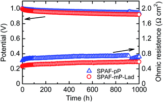 |
| | Fig. 7 OCV hold test of SPAF-pP and SPAF-mP-Lad cells at 80 °C and 30% RH with H2 and air. | |
 |
| | Fig. 8 IR-included polarization curves and ohmic resistance for the SPAF-mP-Lad cell at 80 °C, (a) 100% and (b) 30% RH after OCV hold test for 1000 h. | |
4. Conclusions
We have synthesized SPAF-P-Lad polymer membranes containing sulfone-bond ladder structure by simply treating SPAF-P polymers with oleum. The successful intra-polymer reaction with negligible cross-linked structure was confirmed by GPC (unimodal profiles), 1H NMR spectra (proton chemical shift to much lower magnetic field), and FT-IR spectra (appearance of the peaks assignable to the sulfone bonds). The concentration of the formed intra-sulfone bonds was 1.65 mmolSO2 g−1 for SPAF-pP-Lad, higher than that for SPAF-mP-Lad probably because unsubstituted p-phenylene groups were more reactive than m-phenylene groups in the intra-polymer dehydration reaction. Compared with the parent SPAF-P membranes, SPAF-P-Lad membranes exhibited higher water uptake indicative of enhanced water affinity after treating with oleum albeit little changes of IEC, resulting in the improvement of proton conductivity, especially under low humidity conditions. SPAF-P possessed low glass transition temperature (Tg = 72–90 °C at 60% RH) while the transition was not observed for SPAF-P-Lad under the same conditions since the rigid laddered polymer structure restricted the molecular motion contributing to improved thermo-mechanical stability. In the stress–strain properties, the rigid laddered structure provided SPAF-P-Lad membrane with higher Young's modulus and yield stress but lower maximum strain. SPAF-pP and SPAF-mP-Lad membranes were subjected to fuel cell performance test taking their conductivity and thermo-mechanical properties into account. The fuel cell performance of SPAF-mP-Lad were comparable to those of SPAF-pP at 100% RH and better than those of SPAF-pP at 30% RH because of higher proton conductivity under low humidified conditions. The SPAF-mP-Lad membrane endured open circuit voltage hold test for 1000 h with average decay of as small as 70 μV h−1. The post-analyses suggested negligible degradation of the membrane even under the accelerated testing conditions.
Conflicts of interest
There are no conflicts to declare.
Acknowledgements
This work was partly supported by the New Energy and Industrial Technology Development Organization (NEDO) and by the Ministry of Education, Culture, Sports, Science and Technology (MEXT) Japan through a Grant-in-Aid for Scientific Research (KAKENHI JP18K04746, JP18H02030, JP18H05515, JP18K19111).
References
- H. Zhang and P. K. Shen, Chem. Rev., 2012, 112, 2780 CrossRef CAS.
- Y. Wang, K. S. Chen, J. Mishler, S. C. Cho and X. C. Adroher, Appl. Energy, 2011, 88, 981 CrossRef CAS.
- M. Rikukawa and K. Sanui, Prog. Polym. Sci., 2000, 25, 1463 CrossRef CAS.
- R. S. R. Rafidah, W. Rashmi, M. Khalid and W. Y. Wong, Polymers, 2020, 12, 1061 CrossRef.
- V. Mehta and J. S. Cooper, J. Power Sources, 2003, 114, 32 CrossRef CAS.
- M. Ulbricht, Polymer, 2006, 47, 2217 CrossRef CAS.
- S. Ü. Celik, A. Bozkurt and S. S. Hosseini, Prog. Polym. Sci., 2012, 37, 1265 CrossRef CAS.
- A. Kusoglu and A. Z. Weber, Chem. Rev., 2017, 117, 987 CrossRef CAS.
- Z. Long, J. Miyake and K. Miyatake, J. Mater. Chem. A, 2020, 8, 12134 RSC.
- S.-H. Shin, A. Kodir, D. Shin, S.-H. Park and B. Bae, Electrochim. Acta, 2019, 298, 901 CrossRef CAS.
- M. P. Rodgers, L. J. Bonville, H. R. l. Kunz, D. K. Slattery and J. M. Fenton, Chem. Rev., 2012, 112, 6075 CrossRef CAS.
- M. A. Hickner, H. Ghassemi, Y. S. Kim, B. R. Einsla and J. E. McGrath, Chem. Rev., 2004, 104, 4587 CrossRef CAS.
- J. Miyake and K. Miyatake, Polym. J., 2017, 49, 487 CrossRef CAS.
- T. Mochizuki, M. Uchida and K. Miyatake, ACS Energy Lett., 2016, 1, 348 CrossRef CAS.
- Z. Long, J. Miyake and K. Miyatake, Bull. Chem. Soc. Jpn., 2020, 93, 338 CrossRef CAS.
- J. Miyake, M. Kusakabe, A. Tsutsumida and K. Miyatake, ACS Appl. Energy Mater., 2018, 1, 1233 CrossRef CAS.
- L. Zhang, D. Qi, G. Zhang, C. Zhao and H. Na, RSC Adv., 2014, 4, 51916 RSC.
- M. Li, G. Zhang, S. Xu, C. Zhao, M. Han, L. Zhang, H. Jiang, Z. Liu and H. Na, J. Power Sources, 2014, 255, 101 CrossRef CAS.
- Y. Zhang, Y. Wan, G. Zhang, K. Shao, C. Zhao, H. Li and H. Na, J. Membr. Sci., 2010, 348, 353 CrossRef CAS.
- M. Han, G. Zhang, K. Shao, H. Li, Y. Zhang, M. Li, S. Wang and H. Na, J. Mater. Chem., 2010, 20, 3246 RSC.
- J. Miyake, M. Watanabe and K. Miyatake, RSC Adv., 2014, 4, 21049 RSC.
- Y. Zhang, J. Miyake, R. Akiyama and K. Miyatake, Polymer, 2015, 77, 152 CrossRef CAS.
- J. A. Vanallan, J. Org. Chem., 1956, 21, 1152 CrossRef CAS.
- L. H. Klemm, W. Lane and E. Hall, J. Heterocycl. Chem., 1990, 27, 1969 CrossRef CAS.
- W. Kubo, K. Yamauchi, K. Kumagai, M. Kumagai, K. Ojima and K. Yamada, J. Phys. Chem. C, 2010, 114, 2370 CrossRef CAS.
- D. W. Shin, S. Y. Lee, C. H. Lee, K.-S. Lee, C. H. Park, J. E. McGrath, M. Zhang, R. B. Moore, M. D. Lingwood, L. A. Madsen, Y. T. Kim, I. Hwang and Y. M. Lee, Macromolecules, 2013, 46, 7797 CrossRef CAS.
- T. J. Peckham, J. Schmeisser and S. Holdcroft, J. Phys. Chem. B, 2008, 112, 2848 CrossRef CAS.
- M. Yoshida-Hirahara, S. Takahashi, M. Yoshizawa-Fujita, Y. Takeoka and M. Rikukawa, RSC Adv., 2020, 10, 12810 RSC.
- A. Morin, Z. Peng, J. Jestin, M. Detrez and G. Gebel, Solid State Ionics, 2013, 252, 56 CrossRef CAS.
- B. Yang, Y. Z. Fu and A. Manthiram, J. Power Sources, 2005, 139, 170 CrossRef CAS.
- M. Han, Y.-G. Shul, H. Lee, D. Shin and B. Bae, Int. J. Hydrogen Energy, 2017, 42, 30787 CrossRef CAS.
Footnote |
| † Electronic supplementary information (ESI) available. See DOI: 10.1039/d0ra08630d |
|
| This journal is © The Royal Society of Chemistry 2020 |
Click here to see how this site uses Cookies. View our privacy policy here. 
 Open Access Article
 This Open Access Article is licensed under a Creative Commons Attribution-Non Commercial 3.0 Unported Licence
 *abc
*abc


