
 Open Access Article
 This Open Access Article is licensed under a Creative Commons Attribution-Non Commercial 3.0 Unported Licence
Structure, microstructure and magnetic investigation of the hexagonal δ-FeSe nanophase produced by mechanochemical synthesis†
K. F. Ulbricha,
V. Z. C. Paesb,
J. Geshevb and
C. E. M. Campos *a
*a
aDepartamento de Física, Universidade Federal de Santa Catarina, Florianópolis 88040-970, Brazil. E-mail: carlos.campos@ufsc.br; Tel: +55 48 37212868
bInstituto de Física, Universidade Federal do Rio Grande do Sul, Porto Alegre 91501-970, Rio Grande do Sul, Brazil
First published on 27th October 2020
Abstract
We present a systematic structural, microstructural and magnetic characterization of the hexagonal δ-FeSe nanophase produced by a simple one-step mechanochemical synthesis route, by using conventional X-ray powder diffraction (XRPD), Rietveld refinement, transmission electron microscopy (TEM) and magnetometry techniques. We observed the simultaneous formation of tetragonal β-FeSe and δ-FeSe after 3 h of milling (with minor amounts of unreacted iron), followed by complete β-FeSe → δ-FeSe phase transition as milling time increases to 6 h (no unreacted iron). The average crystallite size of the δ-FeSe phase of about 16 nm after 3 h milling time decreases by about 31% up to the final milling time (24 h). TEM images and electron diffraction patterns confirm the nanometric size of the crystalline domains in the irregularly-shaped agglomerated particles. Two ferromagnetic phases with distinct coercivity spectra were assumed here by considering an assembly of randomly-oriented weakly-anisotropic ferromagnetic particles, mixed at a 4 to 6 volume ratio with other randomly-oriented ferromagnetic grains. Four years after synthesis, the aged samples milled for less than 9 h revealed a certain amount of the β-FeSe phase that slightly affects the δ-FeSe (micro)structure but causes some variations (decreasing) in magnetic parameters. Milling times as long as 12 h were shown to be necessary to guarantee the δ-FeSe nanophase stability and to retain its magnetic properties over time.
1. Introduction
The synthesis of nanoscaled inorganic materials has attracted great attention over the past decades because of their fascinating chemical and physical properties. Among these materials, transition metal chalcogenides represent an important family of compounds that have attracted great interest due to their unique semiconductor,1 superconductor,2 electronic and optoelectronic,3 thermoelectric4 and photovoltaic5 properties. Iron selenides are of particular interest because of their interesting structural and physical properties. Since the discovery of superconductivity in a PbO-type β-FeSe, with critical temperature Tc of ∼8 K,6 it has been fabricated by different syntheses routes7,8 and its properties (superconductivity,9 photocatalytic activity,10 electrochemical sensing10 and fuel-cell applications11) have been widely explored to this day. Although δ-FeSe (structure-type NiAs) has been very well-reported in the literature, it is frequently described as an impurity during the synthesis of β-FeSe superconductors7,12–15 and this phase has been less explored as a potential material for various applications. This is one of the reasons why this article sheds some light on this δ-FeSe nanophase.Hexagonal FeSe has been found to be magnetic with antiferromagnetic or ferrimagnetic behavior, depending on composition.16,17 The Fe–Se phase diagram reveals that the hexagonal δ-FeSe is a high-temperature phase with space group P63mmc that can be retained at room temperature by quenching or Se excess.18 In the same δ-FeSe field of the phase diagram there is a trigonal Fe7Se8 (space group P3121) that can be seen as a superstructure of δ-FeSe phase, which makes them almost impossible to be distinguished by crystallographic methods, especially when these are obtained as nanophases. On the other hand, δ-FeSe and its superstructure Fe7Se8 have completely different magnetic behavior as we showed by Mossbauer spectroscopy.19 Moreover, the local-density approximation and dynamical mean-field theory have shown that δ-FeSe resembles an orbital-selective insulating state.20
In this paper, a simple one-step mechanochemical synthesis of hexagonal δ-FeSe nanocrystalline powders is reported, starting from stoichiometric mixtures of elemental powders of Fe and Se and using high-energy ball milling at room temperature under argon atmosphere. We present how to tune the processing time to obtain specific structural and microstructural characteristics of hexagonal δ-FeSe nanophase. The characterization analyses were performed through conventional X-ray powder diffraction, Rietveld analysis, TEM and magnetization techniques. Four years after synthesis, the aged samples were again analyzed using XRPD and magnetometry techniques, which showed chemical instability and lower values of magnetic parameters.
2. Experimental section
2.1 Solid state synthesis
Starting mixtures of iron (Sigma-Aldrich 97% purity) and selenium (Sigma-Aldrich 99.5% purity) powders with nominal composition of Fe50Se50 were ball-milled in the presence of argon gas up to 24 h using a SPEX Mixer/mill, model 8000D high energy ball mill. The ball-to-powder weight ratio was 10![[thin space (1/6-em)]](https://www.rsc.org/images/entities/char_2009.gif) :1. The synthesis was stopped every third hour in order to fish out a small portion of the sample for ex situ characterization. More synthesis details are found in the earlier work.21 In the synthesis, we assume that the stoichiometry of δ-FeSe (final product after milling) is based on starting ratio powders prior to mechanochemical synthesis.
:1. The synthesis was stopped every third hour in order to fish out a small portion of the sample for ex situ characterization. More synthesis details are found in the earlier work.21 In the synthesis, we assume that the stoichiometry of δ-FeSe (final product after milling) is based on starting ratio powders prior to mechanochemical synthesis.
2.2 Characterizations
Room temperature X-ray powder diffraction (XRPD) measurements were carried out using a vertical-scan Panalytical Xpert Multi-Purpose diffractometer operating in Bragg–Brentano mode with a Cu-Kα radiation (λ = 1.5418 Å), equipped with a linear position-sensitive Xcelerator detector and generator setting: 45 kV and 40 mA. The scanning angle 2θ ranged from 13° to 152° with a step size of 0.06° and a scanning speed of 40 s per step. The aged samples were measurement using a monochromator in the diffraction beam in the 2θ range of 12–105° with a step size of 0.06° and counting time of 280 s per step. Phase identification was obtained by matching the experimental XRPD patterns with those retrieved from the ICSD database. Rietveld refinement was performed via the TOPAS program22 to obtain structural and microstructural parameters. The refinement procedures for this software were as follow: the background was described using Chebyshev polynomials and the order was taken as 8; peak profiles were described by the fundamental parameters approach;23 the Lorentzian and Gaussian contributions to the peak-broadening were refined and respectively associated with the crystal size and to micro-strain effects. Refinable isotropic thermal factors were individually attributed to all atoms of Fe and Se.TEM imaging and Selected Area Electron Diffraction (SAED) measurements were performed at a JEOL JEM-1011 transmission electron microscope operated at an accelerating voltage of 100 kV. JEMS electron microscopy simulation software24 was used to simulate the electron diffraction pattern from the data obtained in the Rietveld refinement.
Vibrating Sample Magnetometer (VSM) measurements were performed at Microsense EV9 system with magnetic field, H, ranging from −20 kOe to 20 kOe at room temperature.
Field-Cooling (FC) and Zero-Field-Cooling (ZFC) magnetization (at an applied field of 100 Oe) and magnetization hysteresis curves up to magnetic fields of 90 kOe were also measured using a Physical Properties Measurement System PPMS (Quantum Design, Dynacool).
3. Results and discussion
3.1 Structural and microstructural characterization
Fig. 1a shows the experimental XRPD patterns of Fe50Se50 samples obtained for different processing (milling) times. The main peaks observed for the sample milled for 3 h were well indexed to the hexagonal δ-FeSe phase with space group P63/mmc (ICSD 53542), accompanied by tetragonal β-FeSe phase and to a tiny quantity of residual cubic Fe (unreacted material). The δ-FeSe stoichiometry is based on starting ratio powders prior to mechanochemical synthesis. However, the Fe:Se ratio of 1:1 is no guarantee of correct δ-FeSe stoichiometry, because this phase can occur in the region from 49.5% to 58% of Se composition of the phase diagram.18 The recent study about the stoichiometry of tetragonal and hexagonal FexSe,25 shows that the FexSe region (from 0.95 to 1.05) is quite critical to the formation (or not) of superconducting phase, with maximum yield of β-Fe1.02±0.01Se occurring at sintering and annealing temperatures of 690 °C and 420 °C, respectively. Moreover, the authors revised the phase diagram in this region and showed that both phases co-exist as exsolution products when formed at temperatures > 350 °C.25
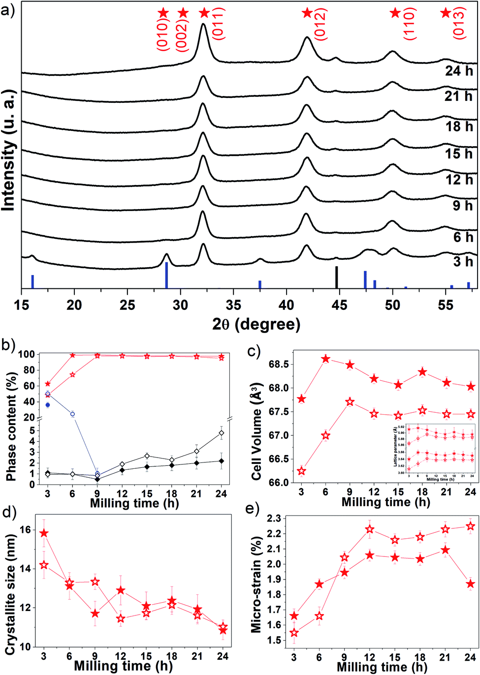 | ||
| Fig. 1 (a) Experimental XRPD patterns (black lines) of the Fe50Se50 fresh samples produced for different processing times. The blue and black bars represent the peak positions and relative intensity of β-FeSe (ICSD 169251) and cubic Fe (ICSD 53802), respectively. The red stars represent the peak positions of δ-FeSe (ICSD 53542). (b) Phase content as a function milling time. Evolution of the δ-FeSe phase parameters: (c) cell volume (with inset of lattice parameters) (d) average crystallite size and (e) micro-strain as a function of processing time. The closed symbols represent the fresh sample and the open ones the aged samples. | ||
The XRPD pattern collected for the sample milled up to 9 h shows only the Braggs peaks referred to the hexagonal δ-FeSe phase, which are broadened due to decreasing of the crystalline domains and/or defects increasing. For longer milling times, the hexagonal δ-FeSe remains as majority phase although traces of cubic Fe reappear in the XRPD patterns. This iron may have been released from the δ-FeSe phase or be due to contamination by milling media; so, we recommend to stop milling before 24 h.
The β → δ phase transition with milling time was proposed by Xia et al.26 that considered changes in the Gibbs free energy of the particles caused by changes in the crystallite size. According to the authors, the smaller the crystallite size the more numerous the atoms located at the interface, resulting in excess surfaces and increasing in the surface energy which consequently increases in Gibbs free energy. They observed that the β → δ phase transition occurs (on powders mixtures of iron and selenium (1:1)) when the crystallite size decreases to a critical dimension of about 15 nm (after 5 h of milling) and is completed when the crystallite size reaches 10 nm (after 10 h of milling). In this work we observed the completed phase transition in about 13 nm with 6 h of milling, in good accordance with Xia et al.
Chebli et al.27 synthesized Fe50Se50 alloy from pure elemental powder mixture by mechanical alloying it up to 39 h. For milling times up to 6 h, the δ-FeSe coexists with amorphous selenium and nanocrystalline α-Fe phases. They, however, observed that after prolonging the milling time to 39 h, there is a formation of β-FeSe phas0e (32.31%) together with δ-FeSe (57.92%) and also the nanocrystalline Fe (8.77%). The average crystallites size is 45 ± 5 nm for β-FeSe phase and 28 ± 5 nm for δ-FeSe phase after 39 h of milling. In this paper, we observed about of 98% of δ-FeSe (with 11 nm and 1.85% of microstrain) and 2% of residual Fe after 24 h of milling. The use of a higher energy mill results in greater processes of fracture and cold-welding mechanisms, reducing the size of crystallites.
Xia et al.26 used a high-energy shaker mill (GN-2, Shenyang Xinke Instrument & Equipment Co., Ltd., China) operated at 480 rpm and weight ratio between balls and powder of 8:1 in argon gas. Chebli et al.27 used a planetary ball mill (Fritsch Pulverisette 7) with rotation speed of 600 rpm and the obtained ball-to-powder mass ratio was 10:1 under argon atmosphere. Here, we used a SPEX Mixer/mill, model 8000D high-energy ball mill (working at 1425 rpm) with the ball-to-powder weight ratio 10:1 under argon atmosphere. These results show that, instead of milling time, the type of mill is a crucial factor in the formation, phase transitions and microstructure modifications of the hexagonal δ-FeSe nanophase.
The Rietveld analysis results are summarized in panels (b–e) of Fig. 1, where it can be seen (Fig. 1b) that after 3 h of milling the sample contains about 63% of δ-FeSe, 36% of β-FeSe and 1% of residual Fe. When increasing milling time, the δ-FeSe phase decreases slightly while the residual Fe increases; with 24 h we obtained 97.8% of δ-FeSe and 2.2% of residual Fe. The increase in residual Fe can be caused by contaminations with the Fe atoms from the steel balls and milling vials due to longer milling time. During milling, the powder particles get trapped between grinding medium, inducing the fracture process that makes the crystallite size domains to decrease, the surface area to increase and the formation of new fresh superficies to occur. The repeated collisions between grinding mediums cause wear and tear of the balls and the vial walls resulting in the incorporation of these impurities into the powder sample.28 One of the most common powder contaminations during milling using a SPEX8000 mill is iron from the steel grinding medium and the steel of the container.29,30
Rietveld analysis revealed that the δ-FeSe phase cell volume increases in the first 6 h of milling (Fig. 1c). The defects accumulated during milling generally cause a lattice expansion, just like the reduction in grain size may cause lattice distortion and an increase of unit cell volume. Fig. 1d shows that the crystallite size decreases significantly in this milling time interval, explaining the increase in the unit cell volume. However, it was observed that the cell volume decreases about 0.85% between 6 and 24 h of milling. The lattice parameters also show the same variation (see the inset in Fig. 1c). This contraction in cell volume and lattice parameter may be attributed to the compressive stress generated in the milling to fracture larger grains into small nanocrystalline fragments. The lattice parameters found by Rietveld refinement show that mechanochemistry introduces a small increase in the lattice parameter a when compared to other syntheses methods,31–33 but not as great as found in ref. 32,34 while the lattice parameter c does not show a clear tendency when compared with other synthesis methods, as shown in Table 1. Whereas, the FeSe@C with a 3D porous interconnected carbon framework the hexagonal-structure of FeSe exhibit lattice parameters a = 3.61 Å and c = 5.87 Å, smaller than those reported in Table 1.35
The average crystallite size of δ-FeSe phase with 3 h of milling is about 16 nm and, as the milling time increases up to 24 h, the crystallite size decreases about 31% (Fig. 1d), reaching its minimum value of about 11 nm. However, the δ-FeSe shows larger crystallite size of 49 nm in the form of thin film prepared by potentiostatic electrodeposition technique.36 The decrease in crystallite size implies in an increase of the micro-strain as seen in Fig. 1e. Micro-strain originates from a number of sources such as vacancies, defects (severe plastic deformation due to milling process which induces defects), shear planes, thermal expansions and contractions, etc. Micro-strain produces a distribution of both tensile and compressive forces, which cause peak broadening in the XRPD patterns. The micro-strain has increased continuously by increasing milling time up to 21 h of milling, when its maximum is achieved. Between 9 and 21 h, the average crystallite size remains almost constant, suggesting that the microstructure of the crystallites is steadily refined. This is in a good agreement with that observed for the micro-strain, which also remains almost constant. However, further milling up to 24 h leads to decrease of micro-strain, suggesting that the energy generated by longer milling times seems to be utilized partly to reduce the particle size and partly as a form of heat energy to reduce the lattice imperfections.37
Four years after synthesis, the aged samples were analyzed using XRPD (see Fig. S1†). We observed that the β-FeSe phase increases about 4% in the 3 h-milled sample and appears in the 6 h (24.6%) and 9 h (1%) samples as shown in Fig. 1b. The 6 h and 9 h fresh samples probably contained some very small amount of β-FeSe phase undetectable by XRPD that grows spontaneously and/or some amorphous content which tends to nucleate such phase using energy stored in defects at interfacial component. The β-FeSe phase growth in FexSe powders, with x = 1.00, 1.25 or 1.50, initially containing the β-FeSe and δ-FeSe phases, have already been reported by us.38 We observed that the β-FeSe phase is the most stable in nanocrystalline samples prepared by mechanochemistry, which can be explained by the defective nature of nanocrystaline phases due to physical mechanisms involved in mechanochemical synthesis, which promote the migration of a large number of atoms to the interfacial component between nanocrystalline domains. The high level of defects in the interfacial component may enhance the diffusivity of Fe and Se atoms, favoring the growth of δ-FeSe nanocrystals. The aging also affects the structure of the δ-FeSe nanocrystals, resulting in lower unit cell volume, indicating a compressive stress. A slight variation in the microstructure was observed with tendency of decreasing in the average crystallite size and increasing of micro-strain.
3.2 Morphological characterization
The microstructure of the Fe50Se50 sample milled for 9 h was studied using TEM. In Fig. 2a, the image collected at lower magnification shows that the sample consists of irregularly shaped aggregates of tiny nanocrystals. The grains are overlapped and though the boundaries of the grains are traceable, it is very difficult to measure the particle sizes via TEM technique. More detailed TEM image from the edge of one aggregate of particles is displayed in Fig. 2b, where crystallites from 6 to 16 nm can be observed. Within these aggregates, the presence of crystallites (randomly oriented) is imaged in the dark field image (Fig. 2d). This kind of morphologies for aggregated nanocrystals are expected since the mechanochemical processing is governed by successive fracture and cold-welding mechanisms. The indexed SAED pattern in Fig. 2c clearly reveals the presence of hexagonal δ-FeSe phase in the 9 h milled sample and confirms the polycrystallinity of the sample. The δ-FeSe obtained from elementary powders heated up to 700 °C for 24 h and ground in the agate mortar for 60 min shows morphology similar, with particle size of about 200 nm and without a well-defined shape.39 | ||
| Fig. 2 (a and b) Bright field TEM images of the Fe50Se50 sample milled for 9 h with different magnifications, (c) SAED pattern and (d) dark-field TEM image for comparison with its counterpart image (a). | ||
3.3 Magnetic characterization
Measurements of the major magnetization hysteresis loops were made at room temperature for the Fe50Se50 samples with different milling times. Fig. 3a shows the hysteresis loops obtained for different milling times (see Fig. S2† for hysteresis loops separately). The similar hysteresis loop shape was observed in δ-FeSe thin films grown by low temperature electrodeposition that exhibited a variation of saturation magnetization and remanence with variation of potential.40 All samples showed no complete magnetization saturation up 20 kOe fields. The M vs. H curves from 3 h up to 9 h of milling show a decrease of the maximum magnetization with the increase of the milling time due to iron disappearance as seen by XRPD. From 12 up to 24 h of milling, the loops have similar shapes, but the values of the maximum magnetization gradually rise with the increase of milling time (Fig. 3b). This behavior can be associated to an increase of residual Fe content. The Rietveld analysis results show that the residual Fe content varies with milling time (see Fig. 1b). We observed that when the residual Fe content increases the maximum saturation also rises. The sample Fe50Se50 with 3 h of milling has about 1.1% of Fe and maximum magnetization of 3.8 emu g−1. However, the sample milled during 24 h contains about 2.2% of residual Fe and maximum magnetization of 8.4 emu g−1. We believe that the increase in residual Fe can be due contaminations with the Fe atoms from the steel balls and vial used in the synthesis due longer milling times (higher than 9 h). Remanent magnetization and coercivity (HC), Fig. 3c and d, show a decrease for 12 h of milling sample, which implies in reducing the area of the hysteresis loop. For long milling times, the remanent magnetization increases while the coercivity remains almost constant. All these observations indicate the presence of coexisting magnetic phases, which ratio can be modified and controlled by the milling time. The M vs. H loops of the aged samples (see Fig. S2†) are very similar to the respective loops of the fresh samples, though with lower values of their magnetic parameters as shown in Fig. 3b and d, probably due to changes in microstructure. | ||
| Fig. 3 (a) VSM measurements of the Fe50Se50 samples milled for 3 h, 6 h, 9 h, 12 h, 15 h, 18 h, 21 h and 24 h. (b) Maximum magnetization, (c) remanent magnetization and (d) coercivity of the Fe50Se50 samples as a function of the milling time. The black and gray squares correspond to the fresh and aged samples, respectively. | ||
The magnetic properties of the 9 h milled Fe50Se50 sample were studied by using PPMS magnetometer at temperatures ranging from 2 to 300 K. Fig. 4a presents the hysteresis loops collected at different temperatures. At 300 K, the sample shows hysteresis loop with a remanent magnetization of 0.15 emu g−1 and HC of 0.14 kOe. The hysteresis loop is clearly opened at 2 K with remanent magnetization of about 0.5 emu g−1 and coercivity of 0.69 kOe (inset in Fig. 4a). As already mentioned, the ferromagnetic contribution can be attributed to the presence of a small amount of elemental unreacted Fe in the sample, which was not observed by XRPD. Both low and high temperature hysteresis loops in this figure show considerable positive slopes at the high-field region up to 90 kOe, which might be attributed to (i) existence of a superparamagnetic phase even at 2 K or, most-probably, to (ii) surface anisotropy which could exceed the anisotropy of the respective bulk material by several orders of magnitude, see, e.g., Chandra et al.41 This is supported by the fact that the loop traced at 2 K does not present effective saturation, i.e., there is no high-field range where the magnetization rotation is reversible.42
 | ||
| Fig. 4 Magnetization data of the Fe50Se50 9 h milled sample. (a) Hysteresis loops taken at 2 K (solid line) and 300 K (dashed line). The inset gives a simulated loop assuming a mixture of two ferromagnetic phases, see the main text. (b) Thermomagnetic magnetization curves (ZFC/FC), measured in an applied field of 100 Oe. | ||
Quite particularly, the low-temperature loop in Fig. 4a has a wasp-waisted (i.e., restricted at the origin) shape, observed in other studies on FeSe systems as well.43,44 Such a characteristic, in a particulate assembly, should be ascribed to a mixture of either superparamagnetic and ferromagnetic phases or of two ferromagnetic phases with distinct coercivities spectra.45–47 The latter case was assumed here and the simulated, for T = 2 K, hysteresis loop shown in the inset of Fig. 4a was obtained by considering an assembly of randomly-oriented weakly-anisotropic (uniaxial anisotropy field of 1.73 kOe) ferromagnetic particles, mixed at a 4 to 6 volume ratio with another randomly-oriented ferromagnetic grains, each with volume of 6.9 × 10⁻²² cm3, spontaneous magnetization of 15 emu cm−3 and uniaxial anisotropy constant equal to 9.1 × 10⁴ erg cm−3. The thermal fluctuations on the quasistatic magnetization processes of this second phase were taken into account. The qualitative agreement with the experiment seems rather good.
The temperature-dependent magnetization behavior of a representative sample was studied, to certain extent, by the zero-field-cooled/field-cooled (ZFC/FC) curves shown in Fig. 4b. The sample was first cooled to 2 K in zero magnetic field, and after application of low external magnetic field of 100 Oe, the ZFC magnetization was measured during warming up to 300 K. The FC curves were recorded during the cooling from 300 K down to 2 K in the same external field. The considerable splitting between FC and ZFC curves indicates that the applied field of 100 Oe is lower than the anisotropy field of this sample at 300 K.42
In order to estimate the effects of magnetic interactions in each of the samples, we employed δMR interaction plots,48 yield from recoil (minor) hysteresis loops of the aged samples. A recoil loop is measured as H is cycled between the maximum positive magnetic field, Hmax, and a smaller (normally negative) field, called recoil field, HR. In systems with uniaxial magnetic anisotropy, nonzero deviations of a δMR(H) are ascribed to magnetic coupling.
Representative major hysteresis loop and a recoil one (with HR = HC) are shown in Fig. 5a, together with the corresponding δMR plot. The δMR plots (also with HR = HC) for the samples ball-milled for periods ranging between 3 and 21 h are given in Fig. 5b. All plots are entirely negative, with very small maximum |δMR|/Mmax values (note that |δMR|/Mmax may attain, theoretically, a maximum value of 2); here Mmax = M(Hmax). It might seem that there is a significant difference between the δMR's amplitudes. However, it is worth noting that these are normalized to Mmax and not to the respective saturation magnetizations, which are impossible to estimate with the Hmax available. Thus, the differences between the δMR plots of our samples might be considered as negligible. The very weak negative (dipolar-like, stabilizing the demagnetized state) interactions inferred indicate a very good dispersion of the magnetic entities throughout each sample, i.e., with insignificant magnetic grains' aggregation.
 | ||
| Fig. 5 (a) Major hysteresis loop (dashed line), a recoil loop with recoil field equal to the coercivity (solid line), and the corresponding δMR plot of the aged Fe50Se50 sample ball-milled for 6 h. (b) δMR plots obtained for HR = HC and for different ball-milling times. | ||
4. Conclusions
Hexagonal δ-FeSe nanocrystallites were successfully synthesized from elemental powder mixture with Fe50Se50 composition by just a few hours of mechanochemical processing with tiny residual Fe in nanometric form. We observed the β → δ phase transition with milling time increasing caused by changes in the samples' microstructure, mainly in its crystallite size. The XRPD and TEM results attested the nanocrystalline character of the samples and allowed to characterize the microstructure for the δ-FeSe nanophase, showing average crystallite size of about 11 nm and micro-strain around 1.85% after 24 h of milling. The samples aged 4 years shows increasing or appearance of the β-FeSe phase for samples with milling time less than 9 h, indicating that the presence of a small amount (even invisible to XRPD) of the β-FeSe phase in the fresh samples tends to grow with the storage time. Magnetic measurements show that the samples have two ferromagnetic phases with distinct coercivities spectra consisting of an assembly of randomly-oriented weakly-anisotropic (uniaxial anisotropy field of 1.73 kOe) ferromagnetic particles, mixed at a 4 to 6 volume ratio with another randomly-oriented ferromagnetic grains, each with volume of 6.9 × 10⁻²² cm3, spontaneous magnetization of 15 emu cm−3 and uniaxial anisotropy constant equal to 9.1 × 10⁴ erg cm−3. Four years after synthesis, the aged samples milled for less than 9 h revealed certain amount of the β-FeSe phase that barely affect the δ-FeSe (micro)structure but causes some variations (decreasing) on magnetic parameters. Milling times as longer as 12 h showed to be determinant to guarantee the δ-FeSe nanophase stability and to keep its magnetic properties over the time.Conflicts of interest
The authors have no conflict of interest in the publication of this manuscript.Acknowledgements
We are grateful to the Brazilian agencies CNPq (grants 421747/2016-1, 310175/2016-0, 305796/2016-0, and 150535/2019-8) and CAPES (K. F. U PhD Scholarship) for financial support. The XRPD, VSM and TEM/SAED/EDS measurements were performed at Laboratório de Difração de Raios-X (LDRX), Laboratório Multiusuário de Caracterização Magnética de Materiais (LabCAM) and Laboratório Central de Microscopia Eletrônica (LCME) multiuser facilities at UFSC.References
- Y. Jun, J. Choi and J. Cheon, Angew. Chem. Int., 2006, 45, 3414–3439 CrossRef CAS.
- A. Subedi, L. Zhang, D. J. Singh and M. H. Du, Phys. Rev. B: Condens. Matter Mater. Phys., 2008, 78, 134514 CrossRef.
- T. Heine, Acc. Chem. Res., 2015, 48, 65–72 CrossRef CAS.
- C. Wan, X. Gu, F. Dang, T. Itoh, Y. Wang, H. Sasaki, M. Kondo, K. Koga, K. Yabuki, G. J. Snyder and R. Yang, Nat. Mater., 2015, 14, 622–627 CrossRef CAS.
- H. Tributsch, J. Electrochem. Soc., 1978, 125, 1086–1093 CrossRef CAS.
- F.-C. Hsu, J.-Y. Luo, K.-W. Yeh, T.-K. Chen, T.-W. Huang, P. M. Wu, Y.-C. Lee, Y.-L. Huang, Y.-Y. Chu, D.-C. Yan and M.-K. Wu, Proc. Natl. Acad. Sci., 2008, 105, 14262–14264 CrossRef CAS.
- Y. Mizuguchi, F. Tomioka, S. Tsuda, T. Yamaguchi and Y. Takano, Appl. Phys. Lett., 2008, 93, 152505 CrossRef.
- M. Ruck, Inorg. Chem., 2012, 51, 7370–7376 CrossRef.
- C. Chang, C. Wang, M. Wen, Y. Wu, Y. Hsieh and M. Wu, Solid State Commun, 2012, 152, 649–652 CrossRef CAS.
- A. K. Dutta, S. K. Maji, D. N. Srivastava, A. Mondal, P. Biswas, P. Paul and B. Adhikary, Appl. Mater. Interfaces, 2012, 2012, 1919–1927 CrossRef.
- R. Azadar, A. Badshah, F. Yasmin and M. Nawaz, J. Organomet. Chem. J., 2014, 769, 58–63 CrossRef.
- X. Li, Z. Ma, Y. Liu, M. Dong and L. Yu, IEEE Trans. Appl. Supercond., 2013, 23, 7000405 Search PubMed.
- C. Koz, M. Schmidt, H. Borrmann, U. Burkhardt, S. Rößler, W. Carrillo-Cabrera, W. Schnelle, U. Schwarz and Y. Grin, Zeitschrift fur Anorg. und Allg. Chemie, 2014, 640, 1600–1606 CrossRef CAS.
- H. Izawa, Y. Tanaka, Y. Mizuguchi and O. Miura, Jpn. J. Appl. Phys., 2016, 55, 053101 CrossRef.
- E. Pomjakushina, K. Conder, V. Pomjakushin, M. Bendele and R. Khasanov, Phys. Rev. B: Condens. Matter Mater. Phys., 2009, 80, 024517 CrossRef.
- T. Hirone, S. Maeda and N. Tsuya, J. Phys. Soc. Japan, 1954, 9, 496–499 CrossRef CAS.
- P. Terzieff and K. L. Komarek, Monatshefte ffir Chemie, 1978, 109, 1037–1047 CrossRef CAS.
- H. Okamoto, J. Phase Equilibria, 1991, 12, 368–372 Search PubMed.
- C. E. M. Campos, J. C. De Lima, T. A. Grandi, K. D. Machado and P. S. Pizani, Solid State Commun, 2002, 123, 179–184 CrossRef CAS.
- L. Craco and S. Leoni, Europhys. Lett., 2011, 92, 67003 CrossRef.
- K. F. Ulbrich and C. E. M. Campos, RSC Adv, 2018, 8, 8190–8198 RSC.
- Total Pattern Analysis System (TOPAS), G. Bruker AXS, Karlsruhe, 2009 Search PubMed.
- R. W. Cheary and A. Coelho, J. Appl. Crystallogr., 1992, 25, 109–121 CrossRef CAS.
- JEMS, v.4, Switzerland Search PubMed.
- M. Shahbazi, H. E. Cathey and I. D. R. Mackinnon, Supercond. Sci. Technol., 2020, 33, 075003 CrossRef.
- Y. Xia, F. Huang, X. Xie and M. Jiang, EPL (Europhysics Lett., 2009, 86, 37008 CrossRef.
- A. Chebli, A. Djekoun, J. J. Suñol and D. Nižňanský, J. Therm. Anal. Calorim., 2020, 140, 53–62 CrossRef CAS.
- C. Suryanarayana, Prog. Mater. Sci., 2001, 46, 1–184 CrossRef CAS.
- T. H. Courtney and Z. Wang, Scr. Metall. Mater., 1992, 27, 777–782 CrossRef CAS.
- E. Hellstern, H. J. Fecht, Z. Fu and W. L. Johnson, J. Appl. Phys., 1989, 65, 305 CrossRef CAS.
- R. S. Kumar, Y. Zhang, S. Sinogeikin, Y. Xiao, S. Kumar, P. Chow, A. L. Cornelius and C. Chen, J. Phys. Chem. B, 2010, 114, 12597–12606 CrossRef CAS.
- G. Hägg and A.-L. Kindström, Zeitschrift für Phys. Chemie, 1933, 22, 453–464 Search PubMed.
- P. Terzieff, H. Schicketanz and L. K. Komarek, Monatshefte fur Chemie, 1982, 113, 519–527 CrossRef CAS.
- D. J. Gawryluk, J. Fink-finowicki, A. Wiśniewski, R. Puźniak and V. Domukhovski, Acta Phys. Pol. A, 2010, 118, 331–335 CrossRef CAS.
- J. Deng, X. Huang, W. Gao, H. Liu and M. Xu, Sustain. Energy Fuels, 2020, 4, 4807–4813 RSC.
- S. Thanikaikarasan and R. Perumal, Mater. Today Proc., 2020, 1–10 Search PubMed.
- O. M. Lemine, Superlattices Microstruct, 2009, 45, 576–582 CrossRef CAS.
- K. F. Ulbrich and C. E. M. Campos, AIP Adv, 2019, 9, 045311 CrossRef.
- K. Wu, F. Chen, Z. Ma, B. Guo, Y. Lyu, P. Wang, H. Yang, Q. Li, H. Wang and A. Nie, Chem. Commun., 2019, 55, 5611–5614 RSC.
- S. Thanikaikarasan, R. Perumal and S. Roji Marjorie, J. Alloys Compd., 2020, 848, 156348 CrossRef CAS.
- S. Chandra, N. A. Frey Huls, M. H. Phan, S. Srinath, M. A. Garcia, Y. Lee, C. Wang, S. Sun, Ò. Iglesias and H. Srikanth, Nanotechnology, 2014, 25, 055702 CrossRef.
- A. Harres, M. Mikhov, V. Skumryev, A. M. H. De Andrade, J. E. Schmidt and J. Geshev, J. Magn. Magn. Mater., 2016, 402, 76–82 CrossRef CAS.
- H. Izawa, Y. Tanaka, Y. Mizuguchi and O. Miura, Jpn. J. Appl. Phys., 2016, 55, 053101 CrossRef.
- A. Galluzzi, M. Polichetti, K. Buchkov, E. Nazarova, D. Mancusi and S. Pace, Supercond. Sci. Technol., 2017, 30, 025013 CrossRef.
- A. P. Roberts, Y. Cui and K. L. Verosub, J. Geophys. Res., 1995, 100, 17909–17924 CrossRef.
- L. Tauxe, T. A. T. Mullender and T. Pick, J. Geophys. Res., 1996, 101, 571–583 CrossRef.
- L. H. Bennett and E. Della Torre, J. Appl. Phys., 2005, 97, 10E502 CrossRef.
- J. Geshev, J. Magn. Magn. Mater., 2018, 467, 135–138 CrossRef CAS.
Footnote |
| † Electronic supplementary information (ESI) available. See DOI: 10.1039/d0ra08519g |
| This journal is © The Royal Society of Chemistry 2020 |