 Open Access Article
Heterogeneous synthesis and electrochemical performance of LiMnPO4/C composites as cathode materials of lithium ion batteries†
Ju-Gong Zheng *a,
Guang-Yuan Rena,
Jun Shia,
Ting Yang*a,
Yue-Feng Tangb and
Yan-Feng Chenb
aFundamental Science on Radioactive Geology and Exploration Technology Laboratory, East China University of Technology, 418 Guanglan Avenue, Nanchang, Jiangxi 330013, China. E-mail: jgzheng@ecut.edu.cn; yt1551@126.com; Fax: +86-791-83896550; Tel: +86-791-83896550
bNational Laboratory of Solid State Microstructures, Nanjing University, 22 Hankou Road, Nanjing, Jiangsu,210093, China
First published on 2nd November 2020
Abstract
In this study, a facile yet efficient interfacial hydrothermal process was successfully developed to fabricate LiMnPO4/C composites. In this strategy, the walls of carbon nanotubes were employed as heterogeneous nucleation interfaces and biomass of phytic acid (PA) as an eco-friendly phosphorus source. By comparing the experimental results, a reasonable nucleation-growth mechanism was proposed, suggesting the advantages of interfacial effects. Meanwhile, the as-synthesized LiMnPO4/C samples exhibited superior rate performances with discharge capacities reaching 161 mA h g−1 at C/20, 134 mA h g−1 at 1C, and 100 mA h g−1 at 5C. The composites also displayed excellent cycling stabilities by maintaining 95% of the initial capacity over 100 continuous cycles at 1C. Electrochemical impedance spectroscopy showed that the superior electrochemical performances were attributed to the low charge-transfer resistance and elevated diffusion coefficient of lithium ions. In sum, the proposed approach for the preparation of LiMnPO4/C composites looks promising for future production of composite electrode materials for high-performance lithium-ion batteries.
1. Introduction
Over the past few decades, rechargeable lithium-ion batteries (LIBs) have widely been used as eco-friendly power sources in portable electronics and large applications, such as electric vehicles and energy storage devices, thanks to their high energy density, long cycle life and good safety.1,2 The current depleting energy resources and the pollution crisis have encouraged the development of clean power sources based on LIBs. One way to achieve this is through the synthesis of high performance materials3,4 as the core component of LIBs, in which cathode materials could directly affect the electrochemical performance and desirable eco-friendliness of the batteries. In recent years, tremendous efforts have been devoted to the development of LIBs materials, such as LiMPO4 (M = Mn, Fe) and LiMPO4 to replace cobalt oxide (LiCoO2) cathode materials used in commercial LIBs with relatively high toxicity, poor thermal stability, and high cost.1,2,5–7 So far, LiMnPO4 is the most promising cathode material for high energy systems8,9 but still suffers from high-current discharge, limiting its extensive applications.10Therefore, numerous modification strategies have been utilized to enhance its electrochemical performances, including improvement of particle dispersion and grain refinement by various synthetic techniques,6,11,12 use of ion doping and solid solution,9,13,14 and coating with electronically conducting agents.15–17 Among these, the hydrothermal strategy is widely adopted for homogeneous synthesis due to its mild operating conditions, non-toxicity, and environmental protection.10 However, LiMnPO4 primary grains are keen on rearranging and stacking along certain directions, leading to the assembly of secondary structures in hydrothermal systems.18–22 The building blocks would inhibit enhanced kinetics and high specific capacity. Therefore, well-dispersed primary particles are urgently expected in the synthesis process.
The rearrangement habits of LiMnPO4 grains are determined by its preferential growth direction. The preferential growth depends on the polarity and energy of the crystal plane.23 In the crystal lattice of LiMnPO4, the polarity of crystal plane is closely related to the areal density of atoms.24 Besides, the interface energy of (100), (010) and (001) planes in LiMnPO4 are differently influenced by the presence of additives and the heterogeneous nucleation interfaces are different.25 Therefore, the addition of additives and the use of heterogeneous nucleation systems could inevitably influence the structure and morphology of LiMnPO4. Wang Y. et al.26 reported a solvothermal synthesis of LiMnPO4/C composites using hexade-cyltrimethylammonium bromide (CTAB) as a surfactant. The authors determined that the morphology is mainly dependant on the amount of CTAB. M. K. Devaraju et al.10 introduced the effects of additives and surfactants on crystal size and morphology of LiMnPO4 nanocrystals in the presence of ascorbic acid. The decrease in particle size to less than 100 nm could be more effective in electrochemical reactions because nanoparticles provide short lengths for lithium ion diffusion during the charge/discharge process. Jing S. et al.27 reported a solvothermal synthesis of LiMnPO4 employing poly(vinyl pyrrolidone) (PVP) as the additive. The as-synthesized LiMnPO4 microstructures exhibit unique, well-shaped and favorable structures, which are self-assembled from microplates or microrods. The b axis is the preferred crystal growth orientation of the products, resulting in a shorter lithium ion diffusion path.
A facile hydrothermal strategy to synthesis well dispersed LiMnPO4 particles was developed by using phytic acid (PA) as phosphorus source. Ethanol, polyethylene glycol and carbon nanotubes were introduced into the ethanol or water to form heterogeneous nucleation system. The heterogeneous nucleation reaction system is highly desired to decrease particle size and increase dispersion of primary particles. The well dispersed LiMnPO4 particles will reduce the Li+ migration length and improve the kinetics of LiMnPO4. As-obtained LiMnPO4/C composites do show a high reversible specific capacity of 158 mA h g−1 at 0.1C, as well as the superior high-rate capability and excellent cycling stability.
2. Experimental
2.1 Synthesis of LiMnPO4 via homogeneous nucleation
In a typical synthesis, 2 mmol PA (Aladdin Chemistry Co., Ltd., 50%) and 36 mmol LiOH·H2O (Alfa Aesar, 98%) were successively dissolved in distilled water under stirring vigorously for 30 min to obtain a brownish yellow transparent solution. Afterward, 12 mmol MnSO4·7H2O (Sigma-Aldrich, 98%) aqueous solution was added to the above obtained brownish yellow solution under magnetic stirring and high-purity nitrogen continuous stream at room temperature for 30 min. Then the mixture was quickly transferred into a 100 mL Teflon-lined stainless-steel autoclave, heated at 180 °C for 6 h, and then naturally cooled to ambient temperature. The as-obtained precipitates were collected by centrifugation and followed by washing several times with distilled water and ethanol, and finally drying in an oven at 60 °C under air atmosphere for 10 h. To determine the appropriate calcination temperatures, the as-prepared precursors were characterized by thermogravimetry and differential scanning calorimetry (TG-DSC, STA449F1, NETZSCH, Germany). The as-prepared precursors were finally transferred to a tube furnace and calcined under a mixed atmosphere of Ar (90%) and H2 (10%). The resulting products were denoted as PA–LMP.2.2 Synthesis of LiMnPO4/C composites via heterogeneous nucleation
First, 300 mg carbon nanotubes (Shenzhen Nanotech Port Co. Ltd, L-MWNT-10-20, outer diameter is about 10–20 nm, length > 5 μm, purity > 75%) were dispersed in 150 mL distilled water to yield a uniform suspension. Next, 36 mmol MnSO4·7H2O were added to the suspension under magnetic stirring to form a heterogeneous nucleation system, which then was divided into three equal volumes for subsequent experiments. Meanwhile, three parts of 2 mmol PA and three portions of 36 mmol LiOH·H2O were separately dissolved into 30 mL distilled water, 30 mL ethanol/water and 30 mL PEG600/water to obtain three mixed solutions. Finally, three mixed solutions were severally dripped into the three heterogeneous nucleation systems with magnetic stirring to yield three different mixtures, which then were quickly transferred into a 100 mL Teflon-lined stainless-steel autoclave followed by reactions, washing, collection, drying and calcination as PA–LMP. The resulting products from water solvent suspension system were denoted as PA–LMP/C, those from ethanol/water solvent suspension system were named as ethanol–PA–LMP/C, and products issued from PEG600/water solvent suspension system were called PEG–PA–LMP/C.2.3 Cells assembly and electrochemical measurement
The fabrication of cathodes and assembly process of CR2032-type coin cells are provided in the ESI (Section I†). The electrochemical performances of LiMnPO4/C composites were evaluated by galvanostatic cycling using CR2032-type coin cells. The charge/discharge performances were collected on battery and cell equipment (Maccor S4000, USA) at different current densities in the voltage range of 2.5–4.5 V vs. Li+/Li. Electrochemical impedance spectroscopy (EIS) was carried out on the electrochemical work station (AUTOLAB PGSTAT30, Metrohm Ltd, Switzerland) over the frequency range of 100 kHz to 0.01 Hz and alternating voltage of 5 mV. All electrochemical measurements were performed in CR2032-type coin cells at room temperature.3. Results and discussion
3.1 TG-DSC analysis
The TG-DSC curves of the precursor are presented in Fig. S1.† The TG curve consisted of three stages with the first two stages showing two obvious weight losses attributed to the dehydration and decomposition of the organic components. In the third stage, an endothermic peak appeared at 550 °C and mainly due to the formation of crystalline phase.28 Almost no weight loss and no thermal effect were observed above 600 °C, indicating the absence of thermal decomposition. Therefore, a calcination temperature of 600 °C was selected and used as optimal value for the preparation of LiMnPO4 materials.3.2 Products prepared via homogeneous nucleation
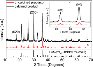
The XRD patterns of products prepared by homogeneous nucleation are presented in Fig. 1. The precursor (Fig. 1a) and calcined product PA–LMP (Fig. 1b) both confirmed the presence of single-phase LiMnPO4 with olivine structure indexed to orthorhombic (JCPDS 74-0375). Moreover, the relative intensities of the characteristic peaks of PA–LMP looked overall higher and more easily indexed than those of precursor. The partial enlargement of two patterns shows the characteristic peaks appeared at16.9° and 29.2° corresponding to (020) and (200) crystal planes. The peak width (FWHM) and the peak intensity of PA–LMP are higher than those of the precursor. Thus, the crystallinities of the products improved by the calcination process.
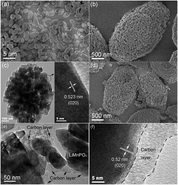
The SEM and TEM images of products prepared from homogeneous nucleation are shown in Fig. 2. The precursor was mainly composed of boat-shaped micro-ellipsoid with major diameters ranging from 3 to 5 μm (Fig. 2a and b). An HRTEM image of a single LiMnPO4 micro-ellipsoid is provided in Fig. 2c. The building blocks were assembled by many nanoparticles side by side in an ordered mode. The fringe spacing value was estimated to about 0.523 nm, consistent with the (020) crystal plane of orthorhombic phase LiMnPO4 with a Pnma space group. Most PA–LMP particles retained their original morphologies, even though scattering of a few primary grains occurred (Fig. 2d). The scattering phenomenon was related to carbonized products. In other words, organic components among the granules can be carbonized during the calcination process, leading to loosing or even separating of tiny blocks. As shown in Fig. 2e and f, the surface of each particle was coated with an unevenly distributed carbon layer. The existence of trace carbon in PA–LMP sample could be attributed to the carbon rings in PA molecules. The amount of carbon in PA–LMP sample determined by elemental analysis was about 1.7 wt%.
3.3 LiMnPO4/C composites synthesized by three heterogeneous nucleation systems
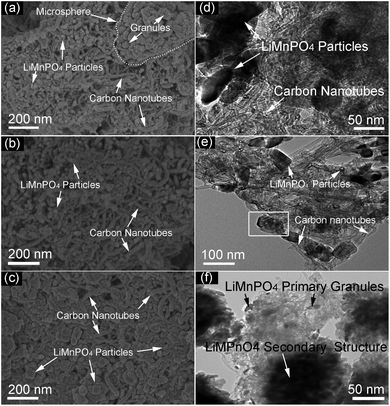 | ||
| Fig. 5 SEM and TEM images of the products synthesized from heterogeneous nucleation systems. (a and d) PA–LMP/C, (b and e) ethanol–PA–LMP/C, (c and f) PEG–PA–LMP/C. | ||
A possible growth mechanism of ethanol–PA–LMP/C composites was proposed based the structural analysis and the results are schematically illustrated in Fig. 6.
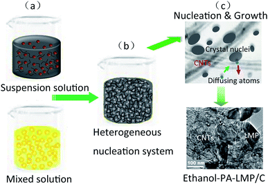 | ||
| Fig. 6 Schematic illustration for the ethanol/water solvent heterogeneous nucleation process of LiMnPO4/C composites. | ||
First, PA was fully dissolved in an ethanol–water mixed solvent, and MWNTs were uniformly dispersed in an aqueous solution containing Mn2+ ions (Fig. 6, step a). During the initial step of the hydrothermal process in the heterogeneous system, numerous tiny nuclei were generated and dispersed in solution or adhering to the walls of MWNTs. Thus PA formed homogeneous hydrogen-containing lithium salt, as well as PA cross-linked complexes with Mn2+ owing to the chelating (Fig. 6, step b).29 In following hydrothermal reaction, the atoms diffused from the solution to the nucleus surface, along with the reverse diffusion from the nucleus to solution. A great number of crystal nuclei were generated on the surface of MWNTs thanks to the relative diffusivity and heterogeneous nucleation caused by interfacial effect. On the other hand, the diffusion activation energy of MWNTs–nucleus interface is higher than that of liquid–nucleus interface. Hence, the surface atoms of MWNTs–nucleus interface could not easily overcome the activation barrier, thereby remained bound to the lattice. In the subsequent process, the crystal nucleus continued to grow up (Fig. 6, step c). By contrast, nucleus in the solution tend to dissolution and aggregate due to thermal undulation.29,31 This led to the assembly of small primary particles with different sizes into secondary microspheres, consistent with the Ostwald ripening theory.32
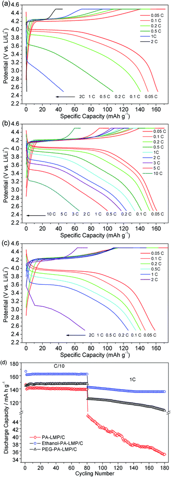 | ||
| Fig. 7 Charge and discharge profiles of PA–LMP/C (a), ethanol–PA–LMP/C (b), PEG–PA–LMP/C (c) and cycling performances of three LiMnPO4/C composites (d). | ||
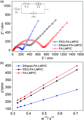
To gain a better understanding of the electrochemical behaviors and kinetics of the three LiMnPO4/C composites, electrochemical impedance spectroscopy (EIS) measurements were performed and the data are shown in Fig. 8. The Nyquist plots and corresponding equivalent circuits in Fig. 8a revealed each impedance spectrum composed of one semicircle component in the high-to-medium frequency range and sloping line component at low frequencies. The high frequency part of the semicircle was related to the formation of EIS films on the electrode surface. The medium frequency part corresponds to charge transfer process. The sloping line in the low-frequency range was associated with the Warburg impedance.37,38 The simulation results estimated the charge-transfer resistance (Rct) values of PA–LMP/C, ethanol–PA–LMP/C and PEG–PA–LMP/C to 274.6, 107.3 and 196.8 Ω, respectively. The EIS of ethanol–PA–LMP/C electrode exhibited a small semicircular domain, indicatingfast charge-transfer process. The charge transfer kinetics were consistent with the superior rate performance and excellent cycling stability.39,40 The Warburg impedance was related to the diffusion of lithium ions in the electrode. The diffusion coefficients of lithium ions (DLi) were calculated according to the following equation:
As shown in the insert of Fig. 8b, the value of σ represented the slope of the lines between the real resistance (Z′) and the inverse square root of the angular frequency (ω−1/2). The DLi values of PA–LMP/C, ethanol–PA–LMP/C and PEG–PA–LMP/C were determined as 1.98 × 10⁻¹³, 8.37 × 10⁻¹³ and 3.16 × 10⁻¹³ cm2 S−1, respectively. The diffusion of lithium ions in ethanol–PA–LMP/C was faster than those in PA–LMP/C and PEG–PA–LMP/C. The rapid diffusion can be attributed to the intrinsic structure of ethanol–PA–LMP/C, consisting of primary particles and continuous MWNTs. The nanosized particles shorten the diffusion distance and provide large current for high rate performance.2,41 In sum, the EIS resultsagree well with the superior electrochemical performance of ethanol–PA–LMP/C.
4. Conclusions
Homogeneous nucleation and heterogeneous nucleation techniquewere employed for the preparation of well-dispersed LiMnPO4/C composites using biomass of phytic acid as phosphorus source. The distribution and microstructure of LiMnPO4 particles can easily be controlled by adjusting the volume ratio of ethanol and dosage of MWNTs. By comparison, LiMnPO4 primary particles prepared by homogeneous nucleation strategy showed apparent aggregations. The products obtained by heterogeneous nucleation system displayed better distribution due to the heterogeneous nucleation interface of MWNTs. This greatly improved the conductivity and migration rate of Li ions. As a result, ethanol–PA–LMP/C samples exhibited superior rate performances with discharge capacities reaching 100 mA h g−1 at 5C, also displayed excellent cycling stabilities by maintaining 95% of the initial capacity over 100 continuous cycles at 1C. Superior rate and excellent cycling performances implies a great potential for use as cathode materials in LIBs. Furthermore, the proposed synthesis strategy could be useful for large-scale synthesis of other materials with eco-friendly and green development aspects.Conflicts of interest
There are no conflicts to declare.Acknowledgements
This research was supported by the National Natural Science Foundation of China (No. 51869002), a grant for National Laboratory of Solid State Microstructures (No. M29033), a grant for Fundamental Science on Radioactive Geology and Exploration Technology Laboratory (No. RGET1811), a project funded by Jiangxi New Energy Technology and Equipment Engineering Technology Research Center (JXNE2016-09), a Test Foundation of Nanjing University.References
- L. Liang, X. Sun, J. Zhang, L. Hou, J. Sun, Y. Liu, S. Wang and C. Yuan, Adv. Energy Mater., 2019, 9, 1802847 CrossRef.
- J. Li, S.-h. Luo, Q. Wang, S. Yan, J. Feng, X. Ding, P. He and L. Zong, J. Electrochem. Soc., 2019, 166, A118–A124 CrossRef CAS.
- W. Chen and H. Fang, J. Electrochem. Soc., 2019, 166, A2752–A2754 CrossRef CAS.
- K. Zhang, G.-H. Lee, M. Park, W. Li and Y.-M. Kang, Adv. Energy Mater., 2016, 6, 1600811 CrossRef.
- V. Ragupathi, P. Panigrahi and G. S. Nagarajan, Appl. Surf. Sci., 2019, 495, 143541 CrossRef CAS.
- N. H. Kwon, H. Yin, T. Vavrova, J. H. W. Lim, U. Steiner, B. Grobéty and K. M. Fromm, J. Power Sources, 2017, 342, 231–240 CrossRef CAS.
- X. Xu, T. Wang, Y. Bi, M. Liu, W. Yang, Z. Peng and D. Wang, J. Power Sources, 2017, 341, 175–182 CrossRef CAS.
- D. Choi, D. Wang, I. T. Bae, J. Xiao, Z. Nie, W. Wang, V. V. Viswanathan, Y. J. Lee, J. G. Zhang, G. L. Graff, Z. Yang and J. Liu, Nano Lett., 2010, 10, 2799–2805 CrossRef CAS.
- V. Aravindan, J. Gnanaraj, Y. S. Lee and S. Madhavi, J. Mater. Chem. A, 2013, 1, 3518–3539 RSC.
- M. K. Devaraju and I. Honma, Adv. Energy Mater., 2012, 2, 284–297 CrossRef CAS.
- J. Zheng, C. Qin, T. Wu, S. Xie, L. Ni, M. Peng, Y. Tang and Y. Chen, J. Mater. Chem. A, 2015, 3, 15299–15306 RSC.
- H. J. Zhu, W. Zhai, M. Yang, X. M. Liu, Y. C. Chen, H. Yang and X. D. Shen, RSC Adv., 2014, 4, 25625–25632 RSC.
- I. Seo, B. Senthilkumar, K.-H. Kim, J.-K. Kim, Y. Kim and J.-H. Ahn, J. Power Sources, 2016, 320, 59–67 CrossRef CAS.
- D. Y. Wang, C. Y. Ouyang, T. Drezen, I. Exnar, A. Kay, N. H. Kwon, P. Gouerec, J. H. Miners, M. K. Wang and M. Gratzel, J. Electrochem. Soc., 2010, 157, A225–A229 CrossRef CAS.
- W. Chen and H. Fang, J. Electrochem. Soc., 2019, 166, A2752–A2754 CrossRef CAS.
- J. G. Duan, Y. B. Cao, J. B. Jiang, K. Du, Z. D. Peng and G. R. Hu, J. Power Sources, 2014, 268, 146–152 CrossRef CAS.
- J. L. Liu, X. Y. Liu, T. Huang and A. S. Yu, J. Power Sources, 2013, 229, 203–209 CrossRef CAS.
- N. Priyadharsini, A. Shanmugavani, S. Surendran, B. Senthilkumar, L. Vasylechko and R. Kalai Selvan, J. Mater. Sci.: Mater. Electron., 2018, 29, 18553–18565 CrossRef CAS.
- J. Zhang, S. Luo, Q. Wang, Z. Wang, A. Hao, Y. Zhang, Y. Liu, Q. Xu and Y. Zhai, J. Alloys Compd., 2017, 701, 433–438 CrossRef CAS.
- Z. Gao, X. L. Pan, H. P. Li, S. K. Xie, R. X. Yi and W. Jin, Crystengcomm, 2013, 15, 7808–7814 RSC.
- T. Li, T. Mei, Y. C. Zhu, H. X. Gong, T. Huang and Y. T. Qian, Chem. Lett., 2011, 40, 837–839 CrossRef CAS.
- J. F. Ni and L. J. Gao, J. Power Sources, 2011, 196, 6498–6501 CrossRef CAS.
- L. Bao, Y. Chen, G. Xu, T. Yang and Z. Ji, Eur. J. Inorg. Chem., 2018, 2018, 1533–1539 CrossRef CAS.
- D. Z. Chen, W. Wei, R. N. Wang, X. F. Lang, Y. Tian and L. Guo, Dalton Trans., 2012, 41, 8822–8828 RSC.
- L. Wang, F. Zhou and G. Ceder, Electrochem. Solid-State Lett., 2008, 11, A94–A96 CrossRef CAS.
- Y. Wang, Y. Yang, Y. Yang and H. Shao, Solid State Commun., 2010, 150, 81–85 CrossRef CAS.
- J. Su, B. Q. Wei, J. P. Rong, W. Y. Yin, Z. X. Ye, X. Q. Tian, L. Ren, M. H. Cao and C. W. Hu, J. Solid State Chem., 2011, 184, 2909–2919 CrossRef CAS.
- J. Zheng, L. Ni, Y. Lu, C. Qin, P. Liu, T. Wu, Y. Tang and Y. Chen, J. Power Sources, 2015, 282, 444–451 CrossRef CAS.
- J. Su, X.-L. Wu, C.-P. Yang, J.-S. Lee, J. Kim and Y.-G. Guo, J. Phys. Chem. C, 2012, 116, 5019–5024 CrossRef CAS.
- A. Salah, P. Jozwiak, J. Garbarczyk, K. Benkhouja, K. Zaghib, F. Gendron and C. Julien, J. Power Sources, 2005, 140, 370–375 CrossRef CAS.
- A. Pimpinelli and J. Villain, Journal, 1998, 60–69 Search PubMed.
- B. P. Jia and L. Gao, Cryst. Growth Des., 2008, 8, 1372–1376 CrossRef CAS.
- A. K. Padhi, K. S. Nanjundaswamy and J. B. Goodenough, J. Electrochem. Soc., 1997, 144, 1188–1194 CrossRef CAS.
- L. F. Zhang, Q. T. Qu, L. Zhang, J. Li and H. H. Zheng, J. Mater. Chem. A, 2014, 2, 711–719 RSC.
- J. Moskon, M. Pivko, I. Jerman, E. Tchernychova, N. Z. Logar, M. Zorko, V. S. Selih, R. Dominko and M. Gaberscek, J. Power Sources, 2016, 303, 97–108 CrossRef CAS.
- Y. Hong, Z. L. Tang, Z. J. Hong and Z. T. Zhang, J. Power Sources, 2014, 248, 655–659 CrossRef CAS.
- J. H. Zheng, Discrete Continuous Dyn. Syst. - Ser. A, 2015, 35, 2273–2298 Search PubMed.
- Y. J. Zhu and C. S. Wang, J. Phys. Chem. C, 2011, 115, 823–832 CrossRef CAS.
- Y. Qian, C. Wang and F. Gao, Biosens. Bioelectron., 2015, 63, 425–431 CrossRef CAS.
- L. E. Li, J. Liu, L. Chen, H. Y. Xu, J. Yang and Y. T. Qian, RSC Adv., 2013, 3, 6847–6852 RSC.
- Y. Qian, F. Gao, L. Du, Y. Zhang, D. Tang and D. Yang, Biosensors and Bioelectronics, 2015, 74, 483–490 CrossRef CAS.
Footnote |
| † Electronic supplementary information (ESI) available. See DOI: 10.1039/d0ra08274k |
| This journal is © The Royal Society of Chemistry 2020 |

