 Open Access Article
Natural gradient composite made of aragonite nanofibers: the ligament of bivalve Acesta marissinica†
Xijin Pan * and
Gangsheng Zhang
School of Resources, Environment and Materials, Guangxi University, 100 Daxue Road, Nanning, Guangxi 53004, China. E-mail: xijinpan2020@163.com
First published on 10th November 2020
Abstract
Here we investigate the nanostructure of the fibrous ligament (FL) in bivalve Acesta marissinica, using scanning electron microscopy (SEM) and an image processing method. We find this FL is mirror symmetrical in its transverse section and consists of aragonite nanofibers and organic materials, the former of which are generally arranged in a featherlike pattern along the mirror plane. Further, we find this FL has a unique graded architecture. From its inner (near the mirror plane) to lateral part (near the ligament–shell junction), the nanofiber angle gradually increases from about 20° to 45°, the nanofiber volume fraction remarkably decreases from 70% to 14%, and the nanofiber diameter also changes from about 137 nm to 85 nm. This novel design allows this FL to be both resilient and strong to meet the biofunctional requirements. We expect the present findings may help us to develop new functionally graded materials (FGMs) and further understand bivalve life processes.
1. Introduction
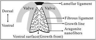
Bivalves are an abundant group of aquatic molluscs with at least 8000 living species.1 They are characterized by a shell composed of two valves joined dorsally by a ligament, the main part of which is called the fibrous (inner) ligament (FL) (Fig. 1).2–8 Although both the valve and FL are mineralized with CaCO3, the former commonly consists of calcite, aragonite, or both, with various structures9–13 and low content of organic matrix (often < 5% by weight).13 In contrast, the latter always consists of aragonite nanofibers3–8 (simplified as nanofibers hereafter) with higher content of organic materials (mainly proteins) (often >25% by weight).4 To date, the valve structure has been extensively studied due to its applications in bio-inspired design and fabrication of advanced materials.9–15 However, the structure of the FL has been neglected in materials science with little literature available. | ||
| Fig. 1 Schematic of the bivalve ligament of Spisula solidissima in transverse section (modified from ref. 3). This ligament consists of a thin lamellar and large fibrous ligament (FL), which grows downward at the ventral surface (growth front). In FL, aragonite nanofibers intersect the growth lines or ventral surface approximately at right angles. | ||
Historically, the FL has been the subject of zoologists and paleontologists for a long time for understanding the bivalve classification and evolution. Therefore, most previous works focus on, for example, its external morphology,16–19 function,20,21 and evolution.2 In addition, some works focus on the organic materials assumed to play a key role in the formation of the FL structure.7,8,22,23 Comparatively, less work focuses on the FL structure. To my knowledge, Trueman firstly studied this subject by optical microscopy (OM)24 and proposed a structural model, which was subsequently confirmed and refined by Kahler et al. by transmission electron microscopy (TEM) and OM (Fig. 1).3 In this model, the nanofibers are straight, discontinuous, and locally aligned with about 100 nm–200 nm in diameter. In addition, the dorsal (early formed) nanofibers vertically intersect the growth lines (laminae), while the ventral (newly formed) nanofibers vertically intersect the ventral surface. Later, Waller2 and Mano25 also got the similar conclusions and predicted that such structure is common to bivalves. However, this model is qualitatively descriptive, considering mainly the nanofiber orientation. Second, it neglects the variation of the nanofiber properties (such as diameter and volume fraction) within an individual FL.
Recently, Zhang et al. confirmed that the nanofibers consist of cobble-like nanograins with different sizes and shapes.6 In addition, Kubota et al. studied the complex formation mechanism of organic materials,7 and Suzuki et al. studied in detail the structure and function of the fusion interphase which connects the ligament to the shell valve.8 These above works greatly advance our understanding of the ligament. Nevertheless, to our knowledge, there are no works focusing on the graded architecture of the bivalve ligament so far.
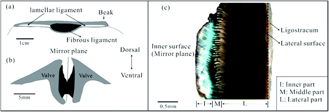
Here, we investigated the FL from Acesta marissinica (Bivalvia, Limidae). This species has a thin but large (up to 22 cm long) shell. Its life style is still not clear, but its relative species A. bullisi has been reported to be sessile (attached to a substrate) with limited swimming ability.26 In particular, this species has a large central FL flanked by two slender lamellar ligaments (Fig. 2a). In living state, this FL is often broken and corroded dorsally along its near mirror plane (Fig. 2b). So, it is easily fractured into two nearly equal halves with the separation of two valves. One half is shown in Fig. 2c. Visually or by OM, it can be roughly divided into three parts: an inner with a green color, middle with a serrated shape, and lateral part with a black color, which occupy about 20–30%, 10–20%, and 50–70% of total ligament thickness, respectively. In addition, a thin ligostracum27 that connects the ligament to the valves will not be discussed in this paper.
The purpose of this work is to examine location-related variation, particularly in the orientation, diameter, and volume fraction of nanofibers along the inner-lateral direction of the FL. We hope quantitative data from this study may help us to develop new FGMs and further understand bivalve life styles.
2. Materials and methods
We bought the specimens of A. marissinica from Sanya Shell Museum in Hainan province of southern China. The shells were washed with distilled water and air-dried for 2 days. Then we carefully separated the shell valves and removed the ligament. Next, using a single blade, we broke the FL in different directions for SEM analysis. Please note that, to minimize artifacts caused during sample preparation, we just air-dried the FL without any further treatment.We took the optical photos using a stereomicroscope (GL-99, GLO) which is connected to a CCD camera (TK-C921EC, JVC).
We examined the FL's structure using SEM (S-3400N, Hitachi) at 30 kV. Then, the SEM images were processed and analyzed using the Fovea Pro 4.0 plug-in (Reindeer Graphics, Asheville, NC) for Adobe Photoshop CS3 (Adobe, San Jose, CA).
3. Results
3.1. Axial arrangement of fibers
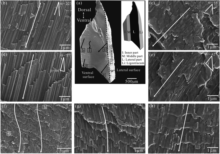
Fig. 3a is a full view of one half of the FL in transverse section, the inset of which is its schematic partition based on OM observation (Fig. 2c). For better describing the nanofiber orientation, we defined the nanofiber angle α as the acute angle between the nanofiber's long axis and lateral surface. | ||
| Fig. 3 SEM images of a half FL in transverse section. (a) A full view. The inset shows its schematic partition based on OM observation (see Fig. 2c). (b and d) Details of the inner part. (c and e) Details of the lateral part. (f) Details of the middle part. (g and h) Close view of marked areas in (f). Single arrow = the fiber axis; dashed line = the lateral surface; α = the angle between the fiber axis and lateral surface; β = the angle between the ventral (newly formed) fiber axis and ventral surface. | ||
SEM analysis shows that the nanofiber orientations, morphology, and packing density gradually change in the inner-lateral direction.
In the inner part (Fig. 3b and d), the nanofibers are continuous, densely packed, and highly aligned with a nanofiber angle α = 22°–17° (mean, ∼20°). Besides, they look like long prisms with a uniform diameter. On the contrary, in the lateral part (Fig. 3c and e), the nanofibers are disrupted, sparsely packed and commonly aligned with a greater nanofiber angle α = 48°–42° (mean, ca. 45°). Besides, they look like irregular spindles with a clearly uneven diameter. Particularly, both in the inner and lateral part, the ventral nanofibers are approximately normal to the ventral surface (β = 86°–98°) (Fig. 3d and e).
While in the middle part, the nanofibers are characterized by a wavy appearance (Fig. 3f). They seem continuous and uniform adjacent to the inner part (Fig. 3g), but are obviously disrupted with a necklace-like shape adjacent to the lateral part (Fig. 3h). Their other features such as the nanofiber angle and packing density lie between those in the inner and later part.
It should be emphasized that the nanofiber properties are gradually varied in the inner-lateral direction, that is, we could not find a clear boundary between above three parts. Thus, we predicted the nanofibers are gradiently arranged in the inner-lateral direction.
3.2. Cross-sectional arrangement of nanofibers
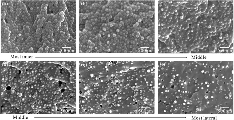
To further confirm the graded arrangement of nanofibers, we observed series of nanofiber's cross sections along the inner-lateral direction, the representative of which are shown in order in Fig. 4. These original images were firstly processed into binary images, from which the nanofiber's diameter and area fraction (=volume fraction for aligned nanofibers) (Table 1) were then extracted by software Fovea Pro 4.0. | ||
| Fig. 4 Representative SEM images of fiber's cross-sections placed in order from the inner (a and b), middle (c and d), and lateral part (e and f) of the fibrous ligament (FL). | ||
| Location | Volume fraction | Mean diameter ± standard deviation | |
|---|---|---|---|
| Inner part | (a) | 70 | 130 ± 12 (n = 613) |
| (b) | 56 | 144 ± 17 (n = 403) | |
| Middle part | (c) | 42 | 141 ± 22 (n = 310) |
| (d) | 39 | 113 ± 29 (n = 269) | |
| Lateral part | (e) | 19 | 83 ± 21 (n = 397) |
| (f) | 14 | 87 ± 23 (n = 272) | |
The result shows that nanofibers are hexagonal to polygonal with their volume fraction and diameter varying continuously along the inner-lateral direction. First, the nanofiber volume fraction decreases significantly from 70% in the most inner part to 14% in the most lateral part (Fig. 4 and Table 1). Second, broadly speaking, the nanofiber diameter, ranging in 130 nm–144 nm (mean, ca. 137 nm) in the inner part, is remarkably larger than that, ranging in 83 nm–87 nm (mean, ca. 85 nm) in the lateral part, thought it shows a slightly fluctuation.
3.3. New structural model for the FL
We have characterized one half of the FL in Section 3.1 and 3.2. Now, considering its mirror counterpart, we could propose a schematic structural model for an intact FL of A. marissinica (Fig. 5). This new model is similar in several aspects to the previous model (Fig. 1). First, the ventral nanofibers are always vertical to the ventral surface. Second, on opposite side of the mirror plane, the nanofibers are oblique to the lateral surface and extend from the lateral to the inner (or ventral) surface, resulting in a pinnate pattern. However, this new model is unique in its graded nanofiber architecture. On each side of the mirror plane, the nanofiber angle, morphology, volume fraction, and diameter vary gradually (Fig. 5c and d). It should be emphasized that the “growth lines” are not observed in the FL of A. marissinica.It should be noted that all bivalve FLs invariably consist of two phases: aragonite nanofibers and proteinaceous organic materials.3–8 The same is true for the FL of A. marissinica, as confirmed by the XRD (X-ray diffraction) and FTIR (Fourier transform infrared) analysis (Fig. S1†). However, these two phases cannot be distinguished by the SEM-EDS (energy dispersive X-ray spectra) because the current SEM-EDS cannot resolve the objects with size smaller than ∼1 μm (Fig. S2 to S4†). That is to say, it cannot resolve the nanofibers with diameter of 83 to 144 nm (Table 1) from the surrounding organic materials.
4. Discussion
In bivalve animals, the opening or closing of two valves is controlled by the ligament and another tissue named adductor muscle.4,16,20,28 When the muscle contracts, the two valves close, compressing the FL to gather elastic energy (Fig. 5a). When the muscle relaxes, the FL recoils, releasing the stored elastic energy to open the valves (Fig. 5b). Therefore, the FL's mechanical properties, especially the resilience and strength in compression, are vital for the surviving of the bivalves such as scallop and Mytilus edulis. For these bivalve FLs, their nanofiber (or CaCO3) content is inversely proportional to the resilience but is proportional to the strength in compression of the FL, as confirmed long ago by Kahler and Trueman.4,20 Based on their results, we hypothesize that the FL of A. marissinica is gradient in the resilience and strength in compression, since the nanofibers content varies gradiently with the location in this FL.Interestingly, the bivalves have evolved various FLs with different nanofiber content to adapt to their life styles. For example, the scallop ligament is nearly unmineralized, which makes it most resilient suitable for the swimming life.20 In this case, the animal is highly mobile enough to escape from predators. In contrast, the ligament in M. edulis is heavily mineralized with 65% nanofibers in weight, which makes it less resilient but strong suitable for the sessile life.4 In this case, the animal is immobile with a strong ligament to stop the valves from being opened by predators. However, in the case of A. marissinica, its ligament is uniquely mineralized with a more flexibly graded architecture. Therefore, we predicted that it may have both the sessile and swimming life style similar to that of A. bullisi.26
On the other hand, morphologically, the FL in A. marissinica is concave at both the dorsal and ventral side, so the area of cross-sections parallel to the mirror plane is not uniform, which gradually increases from the inner to lateral surface. This causes the mean stress (=force/area) acting on the cross-sections gradually decreases with local maximal stress concentrated on the inner surface. Therefore, in response to this stress gradient, the graded arrangement of nanofibers gives a best solution. For example, near the mirror plane where the stress is maximal, the high nanofiber volume fraction of 70% allows the ligament to be strong or stress resistant, while near the lateral surface where the stress is minimal, the low volume fraction of only 14% allows the ligament to be resilient.
Surprisingly, the organic materials in the FL of A. marissinica contain high content of sulphur up to ∼18 wt% (Fig. S3†). However, how it exists is currently unknown, because it needs detailed chemical analysis of the FL which is beyond the scope of this work. Nevertheless, Kahler et al. confirmed that the bivalve ligaments are similar in chemical composition, and mainly consist of aragonite and protein (in differing proportions) with <1 wt% carbohydrates (polysaccharides).3 Particularly, this protein is characterized by having sulfur-containing amino acids, namely, methionine and cystine/2. Recently, Suzuki et al. also confirmed that the ligament of Pinctada fucata consists of aragonite and protein without chitins (polysaccharides).8 Particularly, this protein is rich in methionine residues with ∼4 wt% sulphur by EDS. In addition, no authors report that bivalve ligament contains inorganic sulfates. Therefore, based on the above investigations, we propose that the sulphur in the FL of A. marissinica probably occurs only in the methionine and cystine/2 residues of protein. However, in different bivalve ligament, the protein content varies,3 resulting in that the sulphur content also varies.
Unfortunately, why and how this ligament has evolved the fascinating graded properties are currently unknown. In the future, we intend to further investigate the mechanical properties of the A. marissinica ligament. Particularly, we indent to perform the nanoindentation experiment to elucidate the graded mechanical properties of this ligament.
5. Conclusions
For the first time, we investigated the location-dependent variation of nanostructure in the FL of A. marissinica. We discovered that this ligament have a unique graded structure, in which, along the inner-lateral direction, the nanofiber angle gradually increases from about 20° to 45°, the nanofiber volume fraction decreases significantly from 70% to 14%, and the nanofiber diameter also change from about 137 nm to 85 nm. Therefore, the FL can be regarded as a typical FGM reinforced by nanofibers.Although this work proved that the FL in A. marissinica contains an unusual graded structure, its formation mechanism is still unknown. Obviously, the nanofiber deposition in this structure is controlled mainly by proteins based on the bio-mineralization theory. Moreover, the nanofiber distribution seems closely related with the graded stress distribution. Hence, how the protein and stress precisely control this graded structure needs further work.
Conflicts of interest
There are no conflicts to declare.Acknowledgements
We appreciate the financial support of the National Natural Science Foundation of China (Grant No. 41762004).References
- R. Bieler and P. M. Mikkelsen, J. Linn. Soc. London, Zool., 2006, 148, 223 CrossRef.
- T. R. Waller, The evolution of ligament systems in the Bivalvia, in The Bivalvia ed. B. Morton, Hong Kong University Press, Hong Kong, 1990, p. 49 Search PubMed.
- G. A. Kahler, R. L. Sass and F. M. Fisher, J. Comp. Physiol., 1976, 109, 209 CrossRef CAS.
- G. A. Kahler, F. M. Fisher and R. L. Sass, Biol. Bull., 1976, 151, 161 CrossRef CAS.
- Z. Q. Huang and G. S. Zhang, Micron, 2011, 42, 706 CrossRef CAS.
- J. Zhang, J. Yan and J. Sheng, J. Mater. Sci., 2015, 50, 3383 CrossRef CAS.
- K. Kubota, H. Kintsu, A. Matsuura, Y. Tsuchihashi, T. Takeuchi, N. Satoh and M. Suzuki, Front. Mar. Sci., 2018, 5, 373 CrossRef.
- M. Suzuki, K. Kubota, R. Nishimura, L. Negishi, K. Komatsu, H. Kagi, K. Rehav, S. Cohen and S. Weiner, Acta Biomater., 2019, 100, 1 CrossRef CAS.
- I. Kobayashi and T. Samata, Mater. Sci. Eng. C, 2006, 26, 692 CrossRef CAS.
- X. D. Li, JOM, 2007, 59, 71 CrossRef CAS.
- S. W. Lee, G. H. Kim and C. S. Choi, Mater. Sci. Eng. C, 2008, 28, 258 CrossRef.
- S. M. De Paula and M. Silveira, Micron, 2009, 40, 669 CrossRef CAS.
- E. M. Harper, J. Zool., 2000, 251, 179 CrossRef.
- D. Wallis, J. Harris, C. F. Böhm, D. Wang, P. Zavattieri, P. Feldner, B. Merle, V. Pipich, K. Hurle, S. Leupold, L. N. Hansen, F. Marin and S. E. Wolf, 2020, arXiv preprint arXiv, 05790.
- C. Petit, L. Montanaro and P. Palmero, Int. J. Appl. Ceram. Technol., 2018, 15, 820 CrossRef CAS.
- E. R. Trueman, Ligament, in Treatise on Invertebrate Paleontology, Pt. N, ed. R. C. Moore, The Geological Society of America and University of Kansas Press, Lawrence, 1969, vol. 1, p. 58 Search PubMed.
- T. R. Waller, Philos. Trans. R. Soc. London, Ser. B, 1978, 284, 345 Search PubMed.
- T. Ubukata, Paleobiology, 2003, 29, 369 CrossRef.
- A. F. Sartori and A. D. Ball, J. Molluscan Stud., 2009, 75, 295 CrossRef.
- E. R. Trueman, J. Exp. Biol., 1953, 30, 453 CrossRef.
- K. Ono, Y. Kikuch, K. Higashi, N. Tamiya and N. Yasuoka, J. Biomech., 1990, 23, 307 CrossRef CAS.
- M. Suzuki, T. Kogure, S. Sakuda and H. Nagasawa, Mar. Biotechnol., 2015, 17, 153 CrossRef CAS.
- K. Kubota, Y. Tsuchihashi, T. Kogure, K. Maeyama, F. Hattori, S. Kinoshita, S. Sakuda, H. Nagasawa, E. Yoshimura and M. Suzuki, J. Struct. Biol., 2017, 199, 216 CrossRef CAS.
- E. R. Trueman, Proc. Zool. Soc. London, 1949, 119, 717 CrossRef.
- K. Mano, Journal of Fossil Research, 2003, 3, 37 Search PubMed.
- B. Kohl and H. E. Vokes, Nautilus, 1994, 108, 9 Search PubMed.
- M. R. Carriker and R. E. Palmer, Science, 1979, 206, 691 CrossRef CAS.
- S. A. Wainwright, Nature, 1969, 224, 777 CrossRef.
Footnote |
| † Electronic supplementary information (ESI) available. See DOI: 10.1039/d0ra08035g |
| This journal is © The Royal Society of Chemistry 2020 |


