 Open Access Article
Microporous polymer membrane assisted water induced electricity generation based on triboelectrification and electrostatic induction
Prashant Shukla *a,
Pooja Saxena
 b,
Nitin Bhardwaja and
V. K. Jaina
aAmity Institute for Advanced Research and Studies (Materials & Devices), Amity University, Sector-125, Noida-201303, U.P., India. E-mail: drprashantdb1980@gmail.com
bG L Bajaj Institute of Technology and Management, Greater Noida, Uttar Pradesh, India
First published on 9th November 2020
Abstract
Water in its various forms has been found to be one of the most abundant sources of energy on the planet after solar energy, and hydroelectric power plays a key role in renewable-energy supplies. Traditionally, harvesting tremendous amounts of hydrodynamic energy requires the deployment of complex, bulky, and expensive electromagnetic generators, which become inefficient at lower volumes of flowing or falling water, and then the energy is stored when there is an excess, but these techniques remain largely unperfected. Regardless of the diversity of development strategies, adopted methodologies, and working mechanisms, there are a wide range of energy scavengers, to effectively harness environmental friendly alternative energy sources. Robust, sustainable and technologically effective water energy harvesting devices, especially hydroelectric nanogenerators, are in the research spotlight globally, due to their numerous benefits to society, including cost effectiveness, clean and continuous electricity generation, and environmental applicability. Here the design and working mechanism involved in the development of a microporous polymer membrane assisted unique hydroelectric generator (MPA-HEG) based on triboelectrification and electrostatic induction phenomena is reported, which scavenges energy from continuously dripping water droplets sliding onto the surface of a hydrophobic microporous polymer membrane. MPA-HEG utilizes a very simple architecture that consists of a hydrophobic microporous polymer, poly(tetrafluoroethylene) (PTFE), membrane on a single-sided copper-clad laminate as a substrate and an aluminium electrode. Unlike other reported water energy harvesting devices with similar functionalities, the rational design of MPA-HEG does not necessitate any technologically complex structures to be embedded in the substrate. It has also been revealed that the interaction of water droplets on the smooth, water-resistant solid polymer surface in MPA-HEG switches ‘ON’ and connects the originally disconnected equivalent electrical components at the solid–liquid–solid interfaces, giving an uninterrupted electrical circuit, and transmuting the conservative interfacial effects into a bulk mechanism. Consequently, the instantaneous power output shows a vast increase over equivalent devices that are constrained either to triboelectric interfacial effects or moisture-induced electricity generation. This could serve the purpose of validating the inherent advantages of developing self-powered electronic devices, and this approach can also be effectively exploited for boosted power generation with realistic future applications.
1. Introduction
Over the last few decades, human-induced global warming and environmental changes have become the most catastrophic ecological concerns since increasing utilization of fossil fuels. Alternative sources of power have become of utmost significant due to uncontrolled global energy demands and the devastating effects of air-pollutants on the Earth's atmosphere and environment. These hazardous and detrimental changes necessitate the search for alternative and renewable energy sources, such as solar energy, hydroelectric energy, tidal power, fuel cells, Li-ion batteries, super capacitors, and novel materials for frugal energy innovations for sustainable energy storage.1 The effective and efficient use of alternative energy sources in any form is termed energy harvesting. Harvesting of clean and sustainable energy from the environment is one of the most encouraging tactics used to combat rising power demands, to and to reduce environmental pollution threatening human lives. In particular, the speedy progress in handy miniature electronic devices, and hence, gradually growing demands for battery-free, micro/nano self-powered sensing systems, nanoelectromechanical systems (NEMS), microelectromechanical systems (MEMS) and medical implants and so on are expecting new innovations and developments in the different methods of energy harvesting.2 Recently, several advanced approaches and techniques to develop zero power consumption, highly efficient hybrid energy harvesters have been successfully demonstrated by Vivekananthan et al.3–5As a replenishable source of energy, water envelops nearly 70% of the total surface of the Earth, which shows that it is existing in many different forms starting from tiny rain drops, flowing rivers, ocean waves and tides and so on. Water takes up about 35% of the total solar energy received by Earth and contains an enormous energy of 75 × 1015 W in a variety of forms, namely, thermal, kinetic and chemical energy.6 The chemical energy can be utilized using electricity or photo catalyst assisted water splitting.7 Thermal energy is harnessed for salinity power generation.8 Kinetic energy is traditionally exploited by hydroelectric power stations, which form the foundation of the electricity supply. Typically, electricity generation using hydropower depends primarily on the conversion of the flow or fall of water using complex, heavy weights and bulky electromagnetic generators. Despite, having impressive energy conversion efficiency, hydropower generation on a large scale is most economical and efficient only at high frequencies of flow or fall of water.9,10 Whereas, an abundance of energy stored in the stumpy volume flow or fall of water such as in the form of raindrops, ocean waves and tides, remains mostly unutilized. In the past few years, several capable and advanced systems have been developed for efficient water energy harvesting such as the synthesis of innovatively tailored materials and technically advanced devices with superior transductive governing principles, namely, piezoelectric, triboelectric or electrokinetic effects to efficiently convert low volume and low frequency motion of water into usable electrical energy.11–20
Such abundantly available but still untapped energy content in water can theoretically be scavenged and harnessed using triboelectric nano-generators (TENG), that translate the external mechanical energy into electrical energy by an amalgamation of conventionally well-known triboelectric and electrostatic induction effects, have attracted considerable interest and their use has gathered pace in the energy field.21–26
Two materials which are dissimilar in polarities triboelectrically, can whenever they interact with each other cause the transfer of electrons/ions/material on the surface and as soon as they are parted from each other an electric potential difference is created between them. Whenever, materials with oppositely charged surfaces comes in contact with each other and are separated episodically, electrons are forced to drift via the external load and an unremitting output is generated. Typically, it is mandatory TENG needs a fairly arid environment so that a stable output can be generated, as contact electrification would vanish because of the existence of even traces of water.27
Solid–solid interaction assisted TENG was first technologically advanced by Wang and co-workers in 2012,19 which utilized two solid surfaces of different materials. Then in 2013, the liquid–solid interaction based TENG was proposed which utilized moving liquid interacting with the hydrophobic solid dielectric surface.28,29 The triboelectrification between water and water resistant dielectric polymer film based liquid–solid TENG has the benefit of empowering the direct harvesting of limitless, and easily available, untapped energy sources of water to generate electrical energy without an intricate energy conversion technique.
Porous poly(tetrafluoroethylene) (PTFE) membranes, invented in the 1970s, have recently been introduced as a microporous structured fluoropolymer.30 Its meritorious physical properties include excellent charge retention capacity and stability, low average mass density, high mechanical strength, exceptional biocompatibility and outstanding permeation to water vapours.31,32 The PTFE has also been widely accepted and used as a sensitive material for piezoelectric sensors and strainer sheaths for liquid decontamination.33–35 Due to the tremendously small pore size and the water repelling surface qualities of PTFE, microporous PTFE membranes have received considerable interest because of their broad applications in breathable fabrics.36–40
Lin et al. confirmed that water can also be considered as a promising triboelectric material to produce electrical energy. The triboelectrification phenomena between water and an insulating polymer surface were investigated to harness the energy content in a wave and also to detect the temperature and quantify the existence of alcohol in water.29
A water droplet is comprised of a couple of dissimilar energy types. Firstly, the mechanically influenced energy when it falls as a drop on a medium. Secondly, the electrostatic energy produced during the triboelectrification process with any insulating media which is in-contact with it. The present research work focuses on investigating how to collect both forms, especially the latter. To accumulate the electrostatic energy content in water and demonstrate electricity generation in naturally occurring atmospheric effects such as thunderstorms, Thompson (later Lord Kelvin) invented a water dropper in 1867.41 The water dropper invented by Thompson generated an electrostatically induced electric potential difference between two oppositely charged interconnected systems using the trigger of the non-equilibrium charge dispersal of dropping water.
Several previous research studies have reported that when a droplet of water freely falling from the sky or is allowed to flow through an insulating tube, triboelectricity is generated and then contributes to the water droplet charged surface.42–46 Choi et al. recorded a surface charge density of 4.5 μC m−2 from each water droplet falling out of a PTFE coated tip.42
In the present study, a unique, robust dripping water droplet driven hydroelectric generator is proposed, taking into account the underlying dynamic forces of the water droplets during the process of their contact with the hydrophobic triboelectric layer, which is noticeably unlike the operational principles of the water dropper invented by Thompson. By experimentally investigating the correlation between the dripping and sliding motion of a single droplet of water onto the surface of MPA-HEG and measuring the output parameters, chronological triboelectrification and electrostatic-induction processes are predicted to describe the governing phenomena behind the working of MPA-HEG.
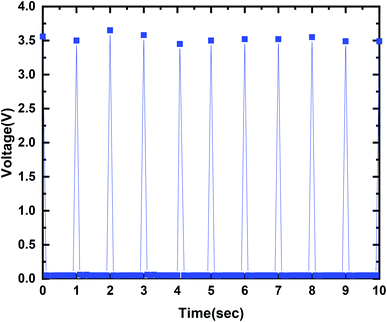
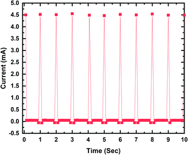
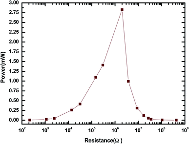
The output current–voltage of the MPA-HEG generated out of a 30 μL water droplet can attain a maximum voltage of 3.5 V and a maximum current of 4.5 mA. A maximum output power of 2.82 mW is seen when the MPA-HEG is connected to a 2 MΩ load resistance. The clean energy from the dripping water droplets collected by the MPA-HEG can be utilized to promptly energize 10–12 commercial LEDs and its rectified output can be used to charge commercial capacitors. The output characteristics of MPA-HEG can be additionally enhanced via incorporating more functional units. Because of the unpretentious structure, cost-effectiveness with easy fabrication and comparatively less complicated to develop compared to other energy scavenging devices, MPA-HEG delivers a clean and green substitute to outmoded approaches for scavenging relatively small amounts of abundantly available water energy in nature.
2. Experimental
2.1. Materials
Chemicals used for cleaning the substrates and laboratory glassware, for example, acetone and ethanol were procured from Merck Life Science Pvt Ltd. Commercially available microporous PTFE film (thickness: 40 μm with different porosities and pore distributions from 0.02 μm to 1 μm) was generously donated for research and development purposes by Blinex Filter Coat Pvt Ltd. (Mumbai, India). Commercially available FR4 grade single sided copper clad laminate (laminate thickness: 1.6 mm and copper sheet thickness: 35 μm) used as one of the electrodes was purchased from a local market based electronic component shop. A conductive aluminium foil based adhesive tape (thickness: 50 μm) used as the second electrode was also procured from a machine tools shop in the local market.2.2. MPA-HEG prototype fabrication
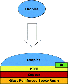
To fabricate the MPA-HEG prototype, the copper layer of a piece of copper clad laminate of size 40 mm × 30 mm × 1.6 mm was cleaned by physically rubbing it using a 320 grit commercially available emery cloth, and then it was cleaned properly with tissue paper using acetone and then ethanol for 2 min each. For fabrication of MPA-HEG a piece of the dielectric layer, i.e., PTFE film was manually fixed using an appropriate conductive glue on the cleaned copper layer, which acted as the first electrode (negative electrode or anode). The other exposed side of the copper clad laminate was already insulated with glass reinforced epoxy resin, which was one of the attributes of the copper clad laminate. A small piece of conducting aluminium tape of size of 1 mm × 5 mm × 50 μm which acts as the second electrode (positive electrode or cathode) was fixed onto the PTFE film. The as fabricated MPA-HEG prototypes had an active triboelectric area of 40 mm × 30 mm, as shown in Fig. 1, using the fluoro-polymer PTFE dielectric layer with high negativity as per the triboelectric series.47 With this device arrangement, the triboelectrification took place at the face of the dielectric layer which was in contact with water. The MPA-HEG utilizes a very simple architecture that comprises a hydrophobic microporous polymer PTFE membrane on a single sided copper clad laminate as substrate and an aluminium electrode. It was postulated that, with continuous dripping of water droplets, the PTFE, an efficient electret material that also has an excellent charge retention capacity and stability, could assist as an ultimate reservoir for charge storage, while inducing electrostatically, charges of the same amount but opposite nature on the substrate, i.e., a single sided copper clad laminate for feasible transfer of charge to the aluminium electrode.2.3. Characterization and electrical measurement set-up for MPA-HEG
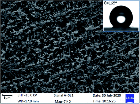
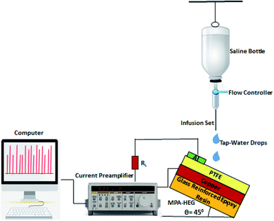
The surface morphology of a microporous PTFE thin film with a porosity of 90% and pore size of 1 μm was observed using a Zeiss EVO 18 scanning electron microscopy (SEM), under an accelerating voltage of 15 kV as shown in Fig. 2. Samples were sputter coated with gold prior to analysis. The PTFE thin film was observed to contain fibrillar and highly dense irregular microstructures. This property of PTFE played a vital role in this concept of efficient harvesting of the hydroenergy in the atmosphere. The hydrophobic nature of the microporous PTFE thin coating was examined by determining the contact angle of the water droplet on it using a GBX Digidrop contact angle meter with a high resolution camera and image processing software. Because, the hierarchical microstructures present within the PTFE film contain trapped air, the real area of contact between the PTFE surface and the water droplet is reduced, causing the PTFE surface to become superhydrophobic. The average value of the recorded contact angle of the PTFE membrane was found to be 165° (inset of Fig. 2). A contact angle >150° is a superhydrophobic surface and thus, the PTFE membrane was validated superhydrophobic.48To measure the output electrical parameters of the MPA-HEG and to demonstrate its proficiency to generate electricity from dripping water droplets, a 500 mL poly(propylene) bottle used for intravenous fluids, was filled with untreated tap-water, attached to an intravenous infusion set with a flow controller and plastic tubing was used to fix the volume of an individual water droplet. The volume of each water droplet was controlled to be 30 μL and allowed to drip down from a height of 20 cm. The dripping rate was also adjusted to 2 mL min−1 which was about 67 drops per min. The exact rate of dripping as well as the volume of the individual water droplet was calibrated by using a graduated measuring cylinder. The schematic diagram for the electrical measurement set-up for MPA-HEG is shown in Fig. 3.
For electrical measurements, all the MPA-HEG architecture and connecting leads were electrically shielded to avoid any short circuiting when the devices interacted with water. The output voltage was measured using an Agilent Technologies InfiniiVision DSOX2002A digital oscilloscope. The output current measurements of the MPA-HEG were performed using an Keithley Tektronix Model 6487 Picoammeter. Other electrical output parameters were recorded using a Keithley Tektronix Model 6514 high precision programmable electrometer, and a Stanford Research Model SR570 low noise current preamplifier, with an external load of 2 MΩ. All of the electrical measurements were performed in an ambient atmosphere, at a temperature of 30 ± 1 °C and relative humidity of 50 ± 2%. The output generated from a 30 μL water droplet can reach a maximum voltage of 3.5 V and a maximum current of 4.5 mA, signifying its potentially wide usage in real life applications. The as-fabricated MPA-HEG devices were kept tilted on a rigid insulating platform at an angle of 45° for rapid liquid detachment. Prior to each electrical measurement, the surface of the triboelectric layer of the MPA-TENG was blown with an ion fan from a distance of 10 cm for 20 s to preserve the consistency of the surface potential. The MPA-HEG was utilized to harvest the energy contained in rainwater drops, and the output current density was found to be 0.075 mA cm−2 and instantaneous power densities of 0.55 mW cm−2, have been achieved, which can light up 10–12 commercial LEDs.
2.4. Demonstration of powering LEDs by MPA-HEG
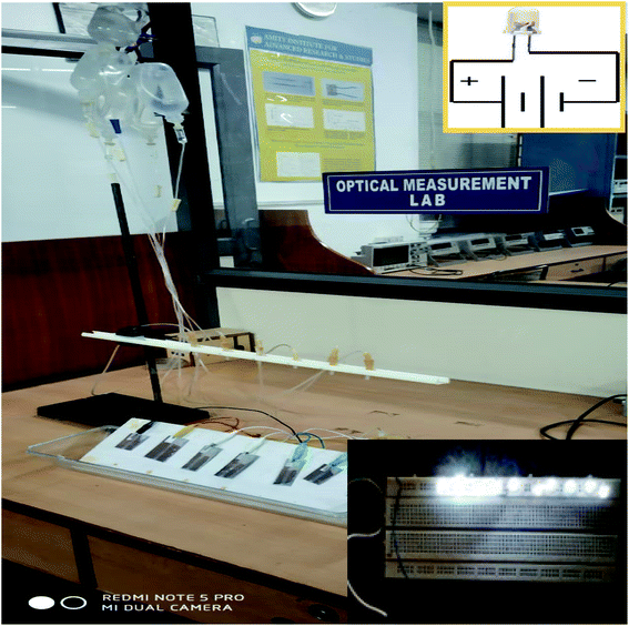
The MPA-HEG was rigidly fixed onto the surface of an insulated wooden panel. Commercially available white colour commercial LEDs (10–12) were connected in series to form an arrangement on a breadboard. The Cu electrode of the MPA-HEG was connected to one end of the LED arrangement. The other end of the LED arrangement was connected to the Al electrode. When the MPA-HEG was operated by dripping the water droplet, its output current would flow through the LED array and light it up as shown in Fig. 4.3. Results and discussion
The functioning mechanism of the MPA-HEG based on the triboelectricity generated from the contact electrification process with the PTFE thin film is shown in Fig. 4. The operation of the MPA-HEG is explained as dual-electrode mode. It should be noted that depending on the counter charges/ions, the water droplet interacts with, the charge on the water droplet can either be positive or negative. In accordance with the experimental data measured as shown in Fig. 3, it was assumed that the water droplet was positively charged to exemplify the procedure of transforming electrostatic energy to electrical energy. An instantaneous negative current was generated by this process. If the water droplet was dripped periodically and came in to contact with the PTFE membrane, an AC output could be continuously produced. To obtain the maximal electrical output, the water drop should be completely wiped off the surface of the PTFE surface before the next droplet was initiated, and this was the primary requirement for superhydrophobicity.Fig. 5 demonstrates the step-by-step representation of the generated and accumulated charges due to contact electrification when the water droplet dripped down on to the porous surface of the PTFE membrane. It is known that when a water droplet was dripping down and gliding onto a fluoropolymer surface, charges due to contact electrification would be generated and contribute to the charged water droplet and the polymer surface.49,50 When a water droplet dripped down and hit the PTFE membrane, the groups on the PTFE surface become ionized, and cause the PTFE film to be negatively charged.42,53 Consequently, an electrical double layer (EDL) which was positively charged, was developed on the contact surface of the water droplet to uphold electrical neutrality (Fig. 5c). As soon as the water droplet leaves the PTFE surface, a negative electric potential difference was established between the Cu electrode (anode) and the Al electrode (cathode). In the case of a short-circuit, negatively charged electrons migrate from the Cu electrode to Al electrode (Fig. 5d) until an equilibrium condition was reached (Fig. 5e). This process generated a prompt negative current. Because the PTFE thin film can retain the triboelectric charges for an extended period of time, when another water drop drips down to contact with the negatively charged PTFE surface, the negative charges on the PTFE will attract their counter charges/ions from the water droplet to develop another EDL which was positively charged and thus, a positive electric potential difference was established. As a result of this, the electrons would migrate from the Al electrode to the Cu electrode (Fig. 5f) until a new equilibrium condition was achieved (Fig. 5g). Consequently, an instant positive current was generated. A negative electric potential difference would be established between the Cu electrode and Al electrode, the moment the water droplet left the surface of the PTFE thin film. Electrons were relocated from the Cu electrode to Al electrode (Fig. 5d) and another new equilibrium condition was established (Fig. 5e). Once the succeeding water droplets were in contact with the PTFE membrane at regular intervals of time (Fig. 5e–h), a continuous output would be obtained.
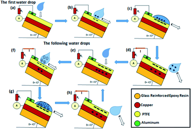 | ||
| Fig. 5 The working mechanism of MPA-HEG when the triboelectricity generated is governed by the contact electrification process of dripping water droplets with the PTFE thin film. | ||
Fig. 6 demonstrates a maximum output voltage of 3.5 V when contact between the dripping droplet of water and the PTFE thin film is made. When the output current value approached 4.5 mA, AC behavior was exhibited as shown in Fig. 7, with a similar number of electrons flowing in each cycle but in the reverse direction. The results 0f the investigation authenticated the governing mechanism for MPA-TENG as shown in Fig. 5. It is also shown that the current peak that corresponded to the separation of the water droplet from the PTFE film had a reduced magnitude but persisted longer than that during their contact. This can be explained on the basis of the fact that separation was a sluggish process, and thus contributed to a reduced but broader current signal.
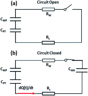
Looking at the MPA-TEG from the perspective of an electrical circuit, the spreading water droplet can be considered as a resistance, Rw and the PTFE film as a capacitor with capacitance, CPT, in which the water–PTFE interface functions as the upper plate and the PTFE–Cu interface as the lower plate. When the electrical circuit was switched OFF, no capacitor was established at the water–aluminium interface, and the circuit continued to be in an open state (Fig. 8a). However, when the circuit was switched ON, capacitors were activated at the water–PTFE interface and the water–Al interface, altering the originally open circuit into a closed loop (Fig. 8b). Given that the thickness of the PTFE was several orders of magnitude larger than that of the EDL at the water–solid interfaces, the capacitance of the capacitor CPT was negligible when compared with that of the capacitors formed at the water-PTFE interface, CWP and the water–aluminium interface CWA. In combination with the high-density surface charges stored in the PTFE, the voltage across CPT was dramatically higher than that across CWP and CWA. The RL and dQ(t)/dt in the circuit were, the impedance of the external load and the derivative of the charges transferred with respect to time, respectively.
Because the triboelectric charges created through the contact electrification process with surrounding air and the PTFE thin film may affect the output parameters of the MPA-HEG, it is important to illustrate and interpret the impact on contact electrification generated due to the distance from which the water droplets are dripping down. On assimilation of the output current peaks of the MPA-HEG obtained for the various heights of the water dripping source away from the PTFE surface, it could be inferred that the number of charges inductively transferred onto the Cu electrode, were always directly proportional to the triboelectrical power generated during the energy scavenging process. It has been experimentally proved that charges transferred inductively were increased with increasing falling heights of the water droplets, but became finally saturated at 20 cm as shown in Fig. 9, thus, confirming the maximal output of the MPA-HEG that a water droplet can yield. This validated the fact that triboelectricity existed only when the water droplet traversed through the air, interacted for a while and then slid down the polymer film, and also specified that it is a realistic concept to harvest the energy confined in rainwater drops.
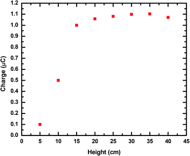 | ||
| Fig. 9 A height (cm) vs. charge (μC) curve showing the effects of the height of the fall of water droplets on the inductively transferred charge of MPA-HEG. | ||
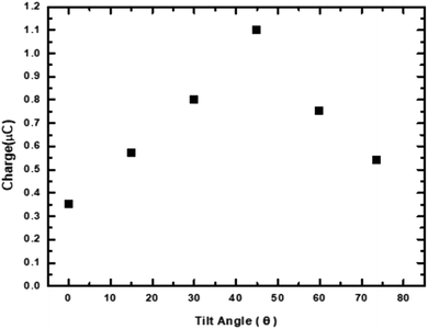
In the context of a wide variety of applications, an important factor of the as-fabricated MPA-TEG, which influenced the dynamics of water droplet interaction with the solid PTFE surface was the inclination or tilt angle (θ). Hence, the effect of increasing and decreasing θ on the inductively transferred charges of the MPA-HEG was examined. The angle θ is shown in the inset of Fig. 10. Fig. 10 represents the inductively transferred charges of the MPA-HEG at different θ varying from 0° to 75°. When θ was increased from 0° to 45°, the inductively transferred charges slightly increased from 0.35–1.1 μC. However, with a further increase in θ beyond 45–75°, the inductively transferred charges diminished back to 0.6 μC. As soon as θ crossed the 45° mark, the operational triboelectric area between the water droplets and MPA-TEG reduced, resulting in fewer water droplets striking the dielectric surface, hence reducing the inductively transferred charges. When θ was as small as 0–10°, water droplets that had fallen on the surface of MPA-TEG cannot slide away as swiftly as when θ was larger. The water retention on the dielectric surface would disrupt the effect of electrostatic induction for the successive water droplets falling down. Because of this quid pro quo between the triboelectric area and the tilt angle for the water droplets to glide away rapidly, the inductively transferred charges reached their maximum when θ was 45°. Because of the hydrophobic nature of the PTFE layer, the tilt angle θ has a small impact on the output of the MPA-TEG. Thus, the electrical output obtained for MPA-TEG at θ = 45° was in complete agreement with the results found in previously published reports.51,52
The electrical output parameters of the MPA-HEG were measured after connecting external loads of a variety of resistances, and the height of fall of the water droplets remained constant at 20 cm. As shown in Fig. 11, it was clear that when the value of the load resistance was less than 0.1 kΩ, the voltage rested close to 0 and there was no significant change in the current. When the resistance value was increased from 0.1 kΩ to 1000 MΩ, the voltage across the load resistance increased, but the current through the load resistance followed a reverse drift direction. Hence, the sudden power on the load remained small when the resistance was below 0.1 kΩ and reached its maximum of 2.82 mW at 2 MΩ for a single water droplet as shown in Fig. 12.
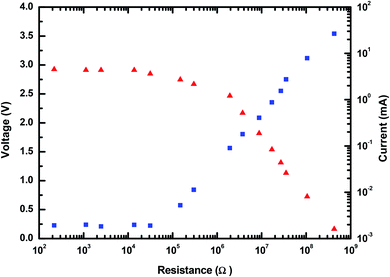 | ||
| Fig. 11 The dependence of the output voltage and current of MPA-HEG on the external load resistance. | ||
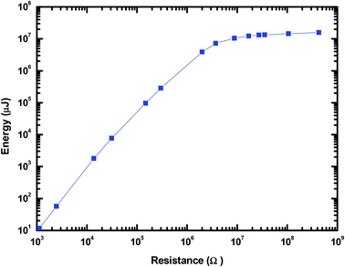
The time integral of I2R gave the output energy of MPA-HEG as calculated and shown in Fig. 13. The curve revealed that the output energy escalated with the escalation in load resistance, and it progressively become constant at a load resistance of 3.74 MΩ (7.2 J), which was five orders of magnitude larger than that of 1.1 kΩ (1.2 × 10⁻⁵ J). After the calculation, it was found that the energy conversion efficiency from the water-related energy to electrical energy for a single water droplet was about 2.1% at a resistance value of 3.74 MΩ. Although, the energy conversion efficiency was small, is believed that it will be improved by collecting the secondary energy of the water drop in the near future.
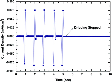
To show that MPA-TENG could be utilized to harness the water-related energy in the environment, and this could be important in the near future because it not only illustrates that the untapped wastewater energy could be collected from the surroundings in daily life but also that we are keen to move ahead to ascertain and expedite new alternative energy sources. To highlight its strong application potential, the MPA-TENG generated current output was divided by its dimensions to yield the output current density as shown in Fig. 14.
It was perceived that the maximum output current density could reach 0.075 mA cm−2 and the signal fluctuations were due to the unstable dripping of the water droplets. The output signal decreased to zero when the dripping of the water droplets was stopped, revealing that the output was generated only because of the water dripping from a fixed height. The AC output generated could be transformed to unidirectional pulsation output by attaching a full-wave rectifying bridge as shown in Fig. 15. The rectified output could be utilized to energize 10–12 commercial LEDs immediately (Fig. 4) and charge a 50 V 22 μF commercial capacitor (Fig. 16). The commercial LEDs were turned on at the very moment, the dripping water droplets contacted the surface of MPA-TENG and totally stopped when the dripping of the water droplets was stopped. The instantaneous peak to peak power density was calculated to be about 0.55 mW cm−2 when the water–TENG was connected to a 2 MΩ load resistor.
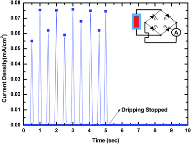 | ||
| Fig. 15 The AC output of MPA-TENG altered to unidirectional pulsation output via a full-wave rectifying bridge. The inset is a diagram of the corresponding circuit connection polarities. | ||
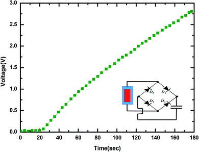 | ||
| Fig. 16 The rectified output used to charge a commercial capacitor of 50 V/22 μF. The inset is a diagram of the corresponding circuit connection polarities. | ||
Energy contained in water droplets such as raindrops is another promising source of energy for applications with little power consumption such as sensors, MEMS and miniaturized electronic devices.54 Recently, an energy harvester made up of a piezoelectric material comprising of PVDF and PZT has been reported to have potential in the conversion of mechanical impact energy of water droplets into electrical energy.55,56 However, there is still no TENG fabricated for collecting energy contained in a raindrop. In this research, it was not only proved that the MPA-HEG is a practical solution for scavenging electrostatic energy in a water droplet but it was also demonstrated that it could have potential for future real life applications.
4. Conclusions
In conclusion, a prototype MPA-HEG with superhydrophobic and self-cleaning features was developed, and it was verified that it had the potential to scavenge the energy contained in dripping water droplets, either from rain or those that were mechanically pipetted. By observing the experimental results obtained, correlation between the motion of a single water droplet on MPA-TENG and the produced output has been deduced, on the basis of which the working mechanism behind electricity generation by MPA-TENG is successfully explained. The output produced from a 30 μL water droplet can reach a maximum voltage of 3.5 V and a maximum current of 4.5 mA, establishing its practical applicability. MPA-TENG was utilized to accumulate the energy from dripping water droplets from a height, and output current and instantaneous power densities of 0.075 mA cm−2 and 0.55 mW cm−2, respectively, have been achieved, which could readily energize 10–12 commercial LEDs. The rectified outputs have also been proved to charge commercial capacitors. All these results clearly show that the innovative ideas behind the unique design of MPA-TENG will be a milestone for future TENG-related research and will also act as a source of inspiration for the development of TENG for determining and simplifying new renewable energy sources from our surroundings in daily life.Authors contribution
Prashant Shukla: methodology, investigation, conceptualization, visualization, writing of the original draft. Pooja Saxena: validation, graphic design, review of writing, and editing. Nitin Bhardwaj: experimental investigation, set up Establishment. V. K. Jain: supervision, review of writing, and editing.Conflicts of interest
The authors declare that there are no conflicts of interest. All authors have approved the manuscript and agree with the submission to your esteemed journal.Acknowledgements
The authors thank Dr Ashok K. Chauhan, founder president of Amity University, for his continuous support and encouragement. The authors would also like to thank other members of the AIARS (M&D) group, Amity University, for their support.References
- S. Xu, Y. Qin, C. Xu, Y. Wei, R. Yang and Z. L. Wang, Nat. Nanotechnol., 2010, 5, 366 CrossRef CAS.
- G. Zhu, J. Chen, T. Zhang, Q. Jing and Z. L. Wang, Nat. Commun., 2014, 5, 3426 CrossRef.
- V. Vivekananthan, N. Prashanth, M. J. Raj, N. Rao Alluri, Y. Purusothaman, A. Chandrasekhar and S.-J. Kim, Appl. Surf. Sci., 2020, 514, 145904 CrossRef CAS.
- V. Vivekananthan, N. R. Alluri, A. Chandrasekhar, Y. Purusothaman, A. Gupta and S.-J. Kim, J. Mater. Chem. C, 2019, 7(25), 7563–7571 RSC.
- V. Vivekananthan, A. Chandrasekhara, N. R. Alluria, Y. Purusothamana, G. Khandelwala, R. Pandeya and S.-J. Kim, Nano Energy, 2019, 64, 103926 CrossRef CAS.
- Z. Zhang, X. Li, J. Yin, Y. Xu, W. Fei, M. Xue, Q. Wang, J. Zhou and W. Guo, Nat. Nanotechnol., 2018, 13, 1109 CrossRef CAS.
- I. Roger, M. A. Shipman and M. D. Symes, Nat. Rev. Chem., 2017, 1, 0003 CrossRef CAS.
- J. M. Salamanca, O. Alvarez-Silva and F. Tadeo, Energy, 2019, 180, 548 CrossRef.
- Y. Zi, H. Guo, Z. Wen, M. H. Yeh, C. Hu and Z. L. Wang, ACS Nano, 2016, 10, 4797 CrossRef CAS.
- H. Kulah and K. Najafi, in Proceedings of the 17th IEEE Conference on Micro Electro Mechanical Systems, IEEE Press, Maastricht, Netherlands, 2004, p. 237 Search PubMed.
- J. H. Lee, H. J. Yoon, T. Y. Kim, M. K. Gupta, W. Seung, H. Ryu and S. W. Kim, Adv. Mater., 2015, 27, 5553 CrossRef CAS.
- J. H. Choi, K. J. Cha, Y. Ra, M. La, S. J. Park and D. Choi, Funct. Compos. Struct., 2019, 1, 045005 CrossRef CAS.
- M. La, J. H. Choi, J. Y. Choi, T. Y. Hwang, J. Kang and D. Choi, Micromachines, 2018, 9, 551 CrossRef.
- Z. H. Lin, G. Chang, S. Lee, K. C. Pradel and Z. L. Wang, Adv. Mater., 2014, 26, 4690 CrossRef CAS.
- W. Kim, H. J. Hwang, D. Bhatia, Y. Lee, J. M. Baik and D. Choi, Nano energy, 2016, 21, 19 CrossRef CAS.
- W. Tang, B. D. Chen and Z. L. Wang, Adv. Funct. Mater., 2019, 29, 1901069 CrossRef CAS.
- R. Hinchet, W. Seung and S. W. Kim, ChemSusChem, 2015, 8, 2327 CrossRef CAS.
- D. Bhatia, W. Kim, S. Lee, S. W. Kim and D. Choi, Nano Energy, 2017, 33, 515 CrossRef CAS.
- F. R. Fan, Z. Q. Tian and Z. L. Wang, Nano energy, 2012, 1, 328 CrossRef CAS.
- D. Jiang, M. Xu, M. Dong, F. Guo, X. Liu, G. Chen and Z. L. Wang, Renewable Sustainable Energy Rev., 2019, 115, 109366 CrossRef.
- G. S. P. Castle, J. Electrost., 1997, 40, 13 CrossRef.
- L. S. McCarty and G. M. Whitesides, Angew. Chem., Int. Ed., 2008, 47, 2188 CrossRef CAS.
- J. A. Wiles, B. A. Grzybowski, A. Winkleman and G. M. Whitesides, Anal. Chem., 2003, 75, 4859 CrossRef CAS.
- X. Cao, Y. Jie, N. Wang and Z. L. Wang, Adv. Energy Mater., 2016, 6, 1600665 CrossRef.
- Y. Jie, N. Wang, X. Cao, Y. Xu, T. Li, X. Zhang and Z. L. Wang, ACS Nano, 2015, 9, 8376 CrossRef CAS.
- L. Jin, B. Zhang, L. Zhang and W. Yang, Nano Energy, 2019, 66, 104086 CrossRef CAS.
- V. Nguyen and R. Yang, Nano Energy, 2013, 2, 604 CrossRef CAS.
- S. Chatterjee, S. Roy Burman, I. Khan, S. Saha, D. Choi, S. Lee and Z. H. Lin, Nanoscale, 2020, 12, 17663 RSC.
- Z. H. Lin, G. Lang, L. Lin, S. Lee and Z. L. Wang, Angew. Chem., Int. Ed., 2013, 52, 12545 CrossRef CAS.
- Z. Xia, A. Buchtemann, R. Danz, A. Wedel and J. Jian, in Proceedings of 11th International Symposium on Electrets, Melbourne, Victoria, Australia, 2002, p. 203 Search PubMed.
- Z. Xia, R. Gerhard-Multhaupt, W. Kunstler, A. Wede1 and R. Danz, J. Phys. D: Appl. Phys., 1999, 32, L83 CrossRef CAS.
- Z. Xia, A. Wede1 and R. Danz, IEEE Trans. Dielectr. Electr. Insul., 2003, 10, 102 CrossRef CAS.
- W. Künstler, Z. Xia, T. Weinhold, A. Pucher and R. Gerhard-Multhaupt, Appl. Phys. A, 2000, 70, 5 CrossRef.
- R. Gerhard-Multhaupt, W. Kunstler, T. Gome, A. Pucher, T. Weinhold, M. Seiss, Z. Xia, A. Wedel and R. Danz, IEEE Trans. Dielectr. Electr. Insul., 2000, 7, 480 CrossRef CAS.
- G. S. Neugschwandtner, R. Schwodiauer, S. Bauer-Gogonea and S. Bauer, Appl. Phys. A: Mater. Sci. Process., 2000, 70, 1 CrossRef CAS.
- M. V. Roey, J. Coated Fabr., 1991, 21, 20 Search PubMed.
- A. Kannekens, J. Coated Fabr., 1994, 24, 51 CrossRef.
- S. Hayashi, N. Ishikawa and C. Giordano, J. Coated Fabr., 1994, 23, 74 CrossRef.
- C. J. Painter, J. Coated Fabr., 1996, 26, 107 CrossRef CAS.
- P. W. Gibson, Polym. Test., 2000, 19, 673 CrossRef CAS.
- S. W. Thomson, Proc. R. Soc. London, 1867, 16, 67 Search PubMed.
- D. Choi, H. Lee, D. J. Im, I. S. Kang, G. Lim, D. S. Kim and K. H. Kang, Sci. Rep., 2013, 3, 2037 CrossRef.
- B. Ravelo, F. Duval, S. Kane and B. Nsom, J. Electrost., 2011, 69, 473 CrossRef.
- T. Takahashi, Rev. Geophys., 1973, 11, 903 CrossRef.
- S. K. Banerji and S. R. Lele, Nature, 1932, 130, 998 CrossRef.
- T. Paillat and G. Touchard, J. Electrost., 2009, 67, 326 CrossRef.
- Y. Xie, S. Wang, L. Lin, Q. Jing, Z.-H. Lin, S. Niu, Z. Wu and Z. L. Wang, ACS Nano, 2013, 7, 7119 CrossRef CAS.
- C. R. Crick and I. P. Parkin, Chem. Commun., 2011, 47, 12059 RSC.
- K. Yatsuzuka, Y. Mizuno and K. Asano, J. Electrost., 1994, 32, 157 CrossRef.
- M. Matsui, N. Murasaki, K. Fujibayashi, P. Y. Bao and Y. Kishimoto, J. Electrost., 1993, 31, 1 CrossRef CAS.
- Y. Liu, N. Sun, J. Liu, Z. Wen, X. Sun, S.-T. Lee and B. Sun, ACS Nano, 2018, 12, 2893–2899 CrossRef CAS.
- Q. Zhang, Q. Liang, Q. Liao, M. Ma, F. Gao, X. Zhao, Y. Song, L. Song, X. Xun and Y. Zhang, Adv. Funct. Mater., 2018, 28, 1803117 CrossRef.
- Z. H. Lin, G. Zhu, Y. S. Zhou, Y. Yang, P. Bai, J. Chen and Z. L. Wang, Angew. Chem., Int. Ed., 2013, 52, 5065 CrossRef CAS.
- S. Roundy and P. K. Wright, Smart Mater. Struct., 2004, 13, 1131 CrossRef.
- R. Guigon, J. J. Chaillout, T. Jager and G. Despesse, Smart Mater. Struct., 2008, 17, 015039 CrossRef.
- M. A. Ahmad and G. E. Jabbour, Electron. Lett., 2012, 48, 647 CrossRef.
| This journal is © The Royal Society of Chemistry 2020 |

