
 Open Access Article
 This Open Access Article is licensed under a Creative Commons Attribution-Non Commercial 3.0 Unported Licence
Ultrafast-charging and long cycle-life anode materials of TiO2-bronze/nitrogen-doped graphene nanocomposites for high-performance lithium-ion batteries†
Thanapat Autthawonga,
Yothin Chimupalabe,
Mitsutaka Harutac,
Hiroki Kuratac,
Tsutomu Kiyomurac,
Ai-shui Yu d,
Torranin Chairuangsrib and
Thapanee Sarakonsri*ae
d,
Torranin Chairuangsrib and
Thapanee Sarakonsri*ae
aDepartment of Chemistry, Faculty of Science, Chiang Mai University, Muang, Chiang Mai 50200, Thailand. E-mail: tsarakonsri@gmail.com
bDepartment of Industrial Chemistry, Faculty of Science, Chiang Mai University, Muang, Chiang Mai 50200, Thailand
cInstitute for Chemical Research, Kyoto University, Uji, Kyoto 611-0011, Japan
dDepartment of Chemistry, Fudan University, Yangpu, Shanghai 200438, China
eMaterial Science Research Center, Faculty of Science, Chiang Mai University, Muang, Chiang Mai 50200, Thailand
First published on 8th December 2020
Abstract
Emerging technologies demand a new generation of lithium-ion batteries that are high in power density, fast-charging, safe to use, and have long cycle lives. This work reports charging rates and specific capacities of TiO2(B)/N-doped graphene (TNG) composites. The TNG composites were prepared by the hydrothermal method in various reaction times (3, 6, 9, 12, and 24 h), while the N-doped graphene was synthesized using the modified Hummer's method followed by a heat-treatment process. The different morphologies of TiO2 dispersed on the N-doped graphene sheet were confirmed as anatase-nanoparticles (3, 6 h), TiO2(B)-nanotubes (9 h), and TiO2(B)-nanorods (12, 24 h) by XRD, TEM, and EELS. In electrochemical studies, the best battery performance was obtained with the nanorods TiO2(B)/N-doped graphene (TNG-24h) electrode, with a relatively high specific capacity of 500 mA h g−1 at 1C (539.5 mA g−1). In long-term cycling, excellent stability was observed. The capacity retention of 150 mA h g−1 was observed after 7000 cycles, at an ultrahigh current of 50C (27.0 A g−1). The synthesized composites have the potential for fast-charging and have high stability, showing potential as an anode material in advanced power batteries for next-generation applications.
Introduction
The necessity of exploring renewable and environmentally compatible alternative energy sources and energy storage systems cannot be underemphasized. Lithium-ion batteries (LIBs) are one of the most effective energy storage systems and have attracted an attention from researchers and industries.1–3 The LIBs draw an attraction for these applications due to high specific capacity, long cycle life, no memory effect, low self-discharge rate, and long shelf life. But despite the numerous advantages over other batteries, LIBs have limitations which limit their uses in applications such as in electric vehicles. These applications require high energy density, good cycling performance, high rate capability, safety in use, and low production cost.4–6 To address these requirements, research on the anode and cathode – principal parts of LIBs – have focused on enhancing their electrochemical properties.7 For anode materials, it is a challenge to obtain a high specific capacity along with the quick charge property, due to the kinetics of Li-ion diffusion in the anode structure. Safety is also an issue that needs to be considered.Currently, graphite is commonly used as a commercial anode material, although it has some severe disadvantages. Graphite allows only one Li-ion intercalated with six carbon atoms, and thus its theoretical capacity is only 372 mA h g−1. Besides, the low diffusion rate of Li-ions is 10−9 cm2 s−1, which proceed batteries with low power density. When graphite is lithiated at low potential (∼0.1 V vs. Li/Li+), an additional concern is also present: the lithium electroplating can cause a short circuit and thermal runaway conditions resulting in the combustion of organic electrolyte and catastrophic battery explosion.8,9 Therefore, industries are looking for new materials to replace graphite.
Si, Ge, and Sn elements that can alloy with lithium and deliver a high theoretical capacity of 4200, 1600, and 994 mA h g−1, respectively, have been investigated for high capacity anodes.10–12 However, problems of high-volume expansion (>400%), poor electron transport, capacity fading, and low coulombic efficiency (CE) have been observed. Nano-structural fabrication of these materials can alleviate these problems.13–15
Moreover, the effective strategy focuses on using a nanocomposite of these elements with various types of carbonaceous materials.16 Specifically, a 2D-graphene sheet, which provides stable and flexible matrices, acts as a mechanical buffering zone against the large volume change problem of the active materials.17,18 The large surface area can contain the active materials and provide the conducting backbone on the 2D-structure.19 Moreover, doping the graphene with atoms such as nitrogen can enhance the specific capacity of the anode material.
Recently, nitrogen-doped graphene (N-doped graphene) has become the trend of anode materials for next-generation LIBs due to its certain properties.20,21 First, electrode/electrolyte wettability is induced by the nitrogen defects on the surface. Second, the types of pyridinic-N and pyrrolic-N, which contained lone electron pairs, can establish a delocalized conjugated system with the sp2-hybridization carbon frameworks to enhance the electrical conductivity. Third, both pyridinic-N and quaternary-N enhance lithium intercalation and extraction, increasing the specific capacity of the anode. In the charged state, a negative field is generated by electron delocalization in pyridinic-N and quaternary-N which offer more active sites and enhance the Li-ion interaction in the graphene structure. Thus, N-doped graphene is a promising anode material for LIBs.22–25
Another alternative anode material is TiO2, which offers advantages of high Li-ion diffusion rate in lithiation processes (∼1.6 V vs. Li/Li+), safety in use, and good stability. Choosing an anode with a higher lithiation potential greatly reduces the chance of a battery explosion.26 Among the polymorphs, bronze-TiO2 (TiO2(B)) is attractive mainly due to high energy density related to the unit cell contains 8 Ti sites and 10 Li-ion sites, giving a theoretical capacity of 1.25 Li+/Ti (∼420 mA h g−1). The open structure of TiO2(B) provides 1D infinite channels, which can accommodate the volume changes.27–29 Interestingly, pseudocapacitive behavior was also reported for TiO2(B), in which the monoclinic crystal structure of TiO2(B) has a low-density crystal framework. These exhibit large channels and voids related to the size of Li-ion that result in a fast Li-ion diffusion rate during the charging/discharging. As a result, the fast charging performance is leaded.30–33 However, the TiO2(B) has a relatively low specific capacity and poor electrical conductivity. These drawbacks could be overcome by combining TiO2(B) with N-doped graphene, which has a high specific capacity and conductivity. The flexibility of the latter would also improve the cycling capability of the LIBs.
In this study, N-doped graphene and TiO2(B) were synthesized and investigated as composite materials by simple chemical method and heat treatment process. The TiO2(B)/N-doped graphene (TNG) composites are expected to have excellent anode material characteristics, having high specific capacity at high current density, adaptive fast charging capability, long life cycle, and high level of safety.
Experimental procedure
N-doped graphene synthesis
N-doped graphene, using a method previously developed by our group34,35 was synthesized using graphite powder as a precursor. To reduce the initial powder size, commercial graphite powder (Sigma-Aldrich, <20 microns, synthetic) was ball milled for 20 h. The modified Hummers' method, which provides an oxidation reaction, was then used to prepare graphene oxide (GO). The GO was obtained as a brown powder after it was dried in the oven at 60 °C and followed by thermal reduction at 800 °C for 5 h under an inert atmosphere to obtain reduced graphene oxide (rGO). Then, melamine (Sigma-Aldrich, 99%), used as a nitrogen source, was homogeneously mixed with the prepared rGO and heat-treated at 800 °C for 1 h under N2 atmosphere to obtain N-doped graphene.TNG composites preparation
In the procedures for synchronous TNG preparation (Fig. S1†), a hydrothermal method was used to prepare TNG composite products. The precursors of anatase-TiO2 (Ajax Finechem, 99%) and N-doped graphene powder in the ratio of 1![[thin space (1/6-em)]](https://www.rsc.org/images/entities/char_2009.gif) :1 were dispersed in 10 M NaOH solution (RCI Labscan, 99%). This suspension was continuously stirred followed by sonicated at room temperature, to obtain a homogeneous suspension. The mixed suspension was transferred into a Teflon autoclave reactor with 70% filling. To study the phase transformation, these suspensions were heated at 180 °C for various reaction times of 3, 6, 9, 12, and 24 h. The hydrothermal products were washed with deionized water to remove the excess NaOH until the pH was ∼7. After pH adjustment, these products were soaked in 0.1 M HNO3 solution (Merck, 65%) for 24 h to promote the ion-exchange process. The soaked products were collected and dried at 80 °C for 12 h. The intermediate samples were heat-treated at 400 °C for 5 h under N2 atmosphere to obtain the TNG composites. The nomenclatures used for the final products were TNG-xh, where x was the hydrothermal reaction time.
:1 were dispersed in 10 M NaOH solution (RCI Labscan, 99%). This suspension was continuously stirred followed by sonicated at room temperature, to obtain a homogeneous suspension. The mixed suspension was transferred into a Teflon autoclave reactor with 70% filling. To study the phase transformation, these suspensions were heated at 180 °C for various reaction times of 3, 6, 9, 12, and 24 h. The hydrothermal products were washed with deionized water to remove the excess NaOH until the pH was ∼7. After pH adjustment, these products were soaked in 0.1 M HNO3 solution (Merck, 65%) for 24 h to promote the ion-exchange process. The soaked products were collected and dried at 80 °C for 12 h. The intermediate samples were heat-treated at 400 °C for 5 h under N2 atmosphere to obtain the TNG composites. The nomenclatures used for the final products were TNG-xh, where x was the hydrothermal reaction time.
Materials characterization
Phases confirmation and crystallinity of the prepared products were analyzed using the powder X-ray diffraction (XRD Rigaku Miniflex II desktop diffractometer with Cu Kα radiation) technique. The morphology, distribution, and crystalline phase of the synthesized products were characterized by scanning electron microscopy (SEM, JEOL JSM-7800F-Prime), and high-resolution transmission electron microscopy (HRTEM, JEOL JEM-2200FS). The electron energy loss spectroscopy (EELS) was measured by scanning transmission electron microscopy equipped with an EELS spectrometer (STEM-EELS, JEM-ARM200F). XPS analysis was conducted using an AXIS ultra DLD spectrometer. Raman spectroscopy was performed with a Jobin Yvon Horiba, model T64000. The specific surface area of N-doped graphene was obtained by Brunauer–Emmett–Teller (BET, Quantachrome Autosorb 1-MP) method. A quantitative analysis was performed by the thermogravimetric analyzer (TGA, Mettler Toledo: TGA/DSC 3+ HT1600).Electrochemical measurement
The half-cells were fabricated in 2032 type coin cells based on the configuration of Li metal(−) |electrolyte| TNG composite(+) with a liquid electrolyte of 1 M lithium hexafluorophosphate (LiPF6) solution in 1:1 ethylene carbonate (EC)-dimethyl carbonate (DMC) + 10% fluoroethylene carbonate (FEC). Both sides of the electrodes were separated by polypropylene (PP, Celgard 2400) separator. To prepare the electrodes, active materials, and conductive Super-P (conductive carbon black, NCM HERSBIT Chemical Co. Ltd) and sodium alginate (SA) binder (Loba Chemie, 99%) were homogeneously mixed with a weight ratio of 70:15:15, which were coated onto a copper foil by a doctor blade. Then, the coated copper foil was dried in a vacuum at 100 °C for 12 h. The 2032 type coin cells were assembled in a glove box under argon atmosphere. The charge–discharge curves and cyclic stability were measured using a battery test system (Neware BTS-4000) at room temperature with the current density of 10C (1C = 539.5 mA g−1) and voltage cut-off between 0.01 and 3.00 V. The rate cycle performance was measured by varying the applied current density from 1C to 50C. In this work, the charge–discharge rates (C rate) of TNG anode are calculated based on the theoretical specific capacity of TiO2 (335 mA h g−1) and graphene (744 mA h g−1).
Results and discussion
N-doped graphene characterizations
The XRD patterns (Fig. S2†) of graphite, GO, rGO, and N-doped graphene were measured in a range of 10° to 60° 2θ. The XRD pattern of GO represented the (001) crystal plane of GO. The experimental d-spacing of graphite was expanded after oxidization in the presence of an oxidizing agent in acid condition. This step caused several oxygens containing groups in the oxidized graphite and then generated an oxygenated graphene layer corresponded to the physical appearance of brownish GO.36 The interlayers distance increased because the oxygen-containing groups were formed on each graphene layer. After the thermal reduction of GO, the XRD pattern of rGO was observed as a broadening diffraction peak at ∼26°. This was caused by poorly ordered graphene stacking and the expanded d-spacing to 3.70 Å. Significantly, the (002) plane of rGO was located at a slightly higher diffraction angle than that of the graphite because oxygen functional groups remained on rGO sheets. In the case of N-doped graphene, the diffraction peak of (002) crystal plane was slightly become a sharp peak compared to rGO. This suggested that nitrogen elements were doped in the graphene layers, substituting some oxygen functional groups, which remained on the graphene surface.Raman spectroscopy was used to study the structure and electronic properties of graphene. The Raman spectra of pristine graphite, GO, rGO, and N-doped graphene (Fig. 1) represented the characteristic spectra of carbon materials including D, G, and 2D bands. Generally, ideal single-layer graphene demonstrates two dominant G and 2D bands. The phonon vibration mode of sp2 of carbon was designated by G-band while the 2D-band was related to several graphene layers. In synthesized graphene, D-band was not only used to determine the defect of graphene sheets but also offered a clear view of defects due to doped nitrogen in the N-doped graphene. From the Raman spectra, the downshifted G peaks of the synthesized GO, rGO, and N-doped graphene products were displayed at 1586, 1579, and 1575 cm−1, respectively. The downshifted G peaks from GO to rGO suggested conjugated structure during the pyrolysis of the oxide functional group. Furthermore, the downshifted G peak of N-doped graphene corresponded to the electron-donating capability of N-heteroatoms.37,38 To estimate the disorder and defect of graphene, the intensities of D and G-bands in Raman spectra, denoted as ID and IG, were used to assign the ID/IG ratio. The ID/IG value of GO was 0.99. The value decreased to 0.91 for rGO because the oxygen functional groups which are distributed on GO were considered as defects. Comparing with N-doped graphene, the ID/IG of N-doped graphene was 1.25, which increased after the nitrogen-doping process. This suggested that N-doped graphene had more defects than rGO, indicating successful nitrogen doping on the graphene sheets. Also, nitrogen-doping induced a lot of topological defects on the graphene surface and increased disorder degree of graphene structure. These resulted in a further increase in lithium storage sites.39
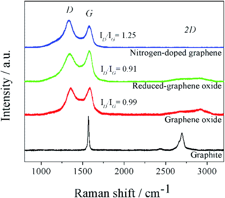 | ||
| Fig. 1 Raman spectra of pristine graphite, GO, rGO, and N-doped graphene. | ||
XPS technique was carried out to explore the binding configuration of the N-doped graphene structure. Three peaks of the XPS survey spectrum (Fig. 2(a)) were present at 284.3, 398.3, and 533.3 eV, corresponding to C 1s, N 1s, and O 1s, respectively. The O 1s peak came from the water absorption on the N-doped graphene surface, asides from oxygen residues in GO which had thermal stability.40,41 The high magnified XPS curve fitting of C 1s was displayed in Fig. S3† in the range of 275–300 eV. The C 1s spectrum of N-doped graphene shows fitting peaks. C 1s spectrum of N-doped graphene contained four peaks at the binding energy of 284.0, 285.0, 285.9, 286.7, 287.6, and 288.8 eV, corresponding to carbon (C–C), sp2 carbon (C![[double bond, length as m-dash]](https://www.rsc.org/images/entities/char_e001.gif) C), N-sp2 carbon (CN), C–O bonds, N-sp3 carbon (C–N) bonds and CO bonds, respectively.36,42 The C–C and CC bonds were assigned to conjugated carbons in a planar honeycomb lattice of graphene. The C–N and CN bonds could be generated from the substitution of nitrogen atoms located at the defect or edge of the graphene structure, confirming the formation of N-doped carbon. The schematic structure of nitrogen bonding configurations of N-doped graphene is illustrated in Fig. 2(c). The XPS N 1s spectra in Fig. 2(b) show three types of nitrogen states, including pyridinic-N (398.6 eV), pyrrolic-N (400.1 eV), and quaternary-N (401.5 eV).43,44 The high amount of nitrogen-doped was observed in pyridinic-N and pyrrolic-N. Both nitrogen functional groups had high electronegativity comparing to carbon which affected the cumulative escalation of the interaction between the carbon-nitrogen doped position in the carbon structure and Li-ions in the electrolyte. Moreover, the surface area of N-doped graphene was also measured at 714.03 m2 g−1, which was relatively high compared to that of the graphite precursor (45.19 m2 g−1). These properties give the increment of the reversible specific capacity of N-doped graphene.39
C), N-sp2 carbon (CN), C–O bonds, N-sp3 carbon (C–N) bonds and CO bonds, respectively.36,42 The C–C and CC bonds were assigned to conjugated carbons in a planar honeycomb lattice of graphene. The C–N and CN bonds could be generated from the substitution of nitrogen atoms located at the defect or edge of the graphene structure, confirming the formation of N-doped carbon. The schematic structure of nitrogen bonding configurations of N-doped graphene is illustrated in Fig. 2(c). The XPS N 1s spectra in Fig. 2(b) show three types of nitrogen states, including pyridinic-N (398.6 eV), pyrrolic-N (400.1 eV), and quaternary-N (401.5 eV).43,44 The high amount of nitrogen-doped was observed in pyridinic-N and pyrrolic-N. Both nitrogen functional groups had high electronegativity comparing to carbon which affected the cumulative escalation of the interaction between the carbon-nitrogen doped position in the carbon structure and Li-ions in the electrolyte. Moreover, the surface area of N-doped graphene was also measured at 714.03 m2 g−1, which was relatively high compared to that of the graphite precursor (45.19 m2 g−1). These properties give the increment of the reversible specific capacity of N-doped graphene.39
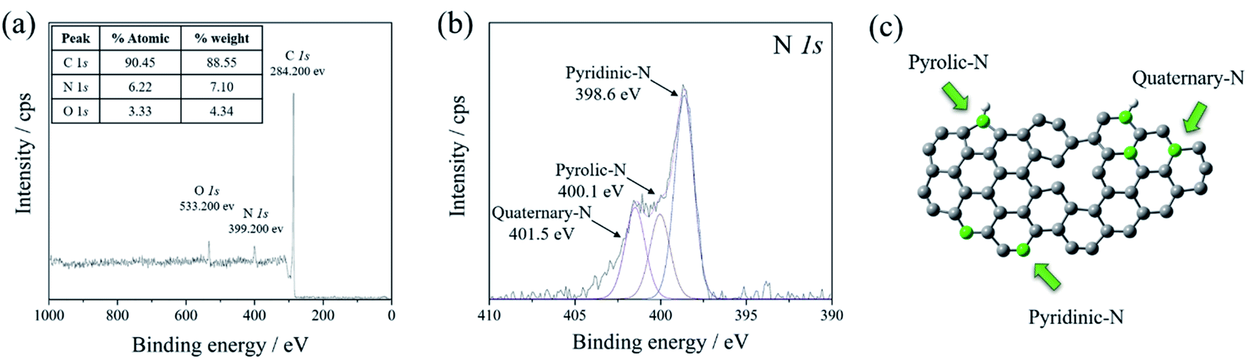 | ||
| Fig. 2 (a) XPS survey spectra of N-doped graphene, and the high magnified curve fitting of (b) N 1s spectra. (c) The schematic structure of nitrogen bonding configurations of N-doped graphene. | ||
As the graphene-based materials are intercalation materials, a huge specific surface area is an important characteristic of synthesized graphene that determines the interface interaction between graphene and Li-ion during charge–discharge processes. To determine the specific surface area of synthesized graphene, N2 adsorption is commonly used as the analytical technique, where the Brunauer–Emmett–Teller (BET) theory is generally used to analyze the adsorption data.45 The specific surface areas (SBET) of graphite, rGO, and N-doped graphene are shown in Table 1. The surface areas of rGO and N-doped graphene were larger than that of graphite due to the exfoliation of the graphitic layer.46 The results further show that more single-, few-layer structures were manufactured in rGO by thermal exfoliation at high temperature, hence has a higher specific surface area. Besides, heat-treating N-doped graphene with melamine could significantly shrink the graphene interlayers, indicated by the increased ID/IG value. The surface area difference between synthesized graphene and individual isolated graphene sheets47 which has the-theoretical surface area of 2630 m2 g−1, implied that rGO and N-doped graphene were composed of multilayered graphene sheets. This was consistent with the results of XRD, SEM, and Raman spectroscopy.
| Graphite | rGO | N-doped graphene | |
|---|---|---|---|
| Specific surface area, SBET (m2 g−1) | 120.00 | 949.10 | 714.03 |
TNG nanocomposites characterizations
The physical and structure information of prepared TNG composites materials were further characterized by several techniques, including XRD, SEM, HRTEM, and STEM-EELS. As shown in Fig. 3, the XRD patterns displayed the crystalline phase of TNG in various hydrothermal reaction time conditions. The characteristic peaks at 36–38° of anatase-phase TiO2 (JCPDS no. 21-1272) matched very well with the TNG-3h and TNG-6h samples, suggesting that the reaction times below 6 h were not enough to transform anatase phase to TiO2(B) phase (JCPDS no. 46-1238). However, the XRD patterns of TNG-9h were difficult to identify exactly as the TiO2(B) phase due to the weak intensity. Therefore, the exact crystalline phase needed to be identified by other techniques, namely HRTEM and STEM-EELS. In the case of TNG-12h and TNG-24h products, their XRD patterns could be clearly indexed as the TiO2(B) phase. Because the most intense peak of TiO2(B) (110) and N-doped graphene (002) was at 2θ of 24.5° and 26°, respectively.48,49 The XRD patterns of the composites appeared as a broad peak with a shoulder of the higher angle. These indicated the formation of mixed TiO2(B) and N-doped graphene in these prepared products.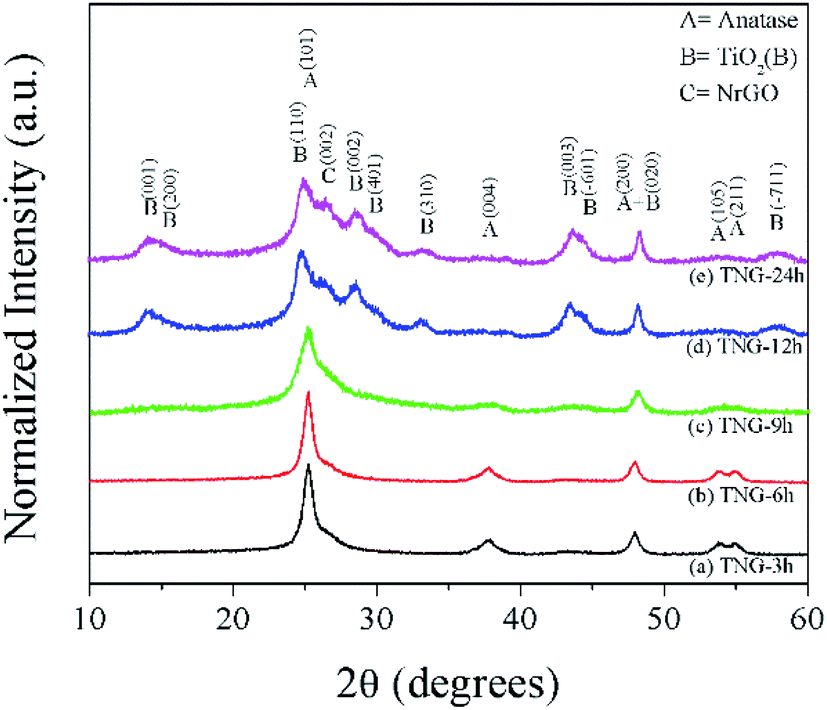 | ||
| Fig. 3 XRD patterns of the prepared products. The labels of diffraction patterns for anatase, TiO2(B), and N-doped graphene are shown for reference. | ||
To observe the morphology of the synthesized samples, SEM images of bare N-doped graphene and TNG in various reaction times are shown in Fig S4.† The surface topography of N-doped graphene (Fig S4(a)†) displays significantly delaminated graphene layers, forming a porous structure, as a result of thermal exfoliation. Normally, the main physical forms of TiO2(B) products after hydrothermal synthesis represent the one-dimensional morphologies such as rod, ribbon, tube, and wire. In this experiment, TNG-3h and TNG-6h, illustrated in Fig S4(b) and (c),† respectively, appeared as the small particle agglomeration of TiO2, decorating on N-doped graphene layers. Therefore, these particles belong to the anatase phase, in agreement with the XRD results. Fig. S4(d)† shows the SEM image of the TNG-9h product, in which TiO2 nanowire was well dispersed on the surface of N-doped graphene. Furthermore, the topography of TNG-12h and TNG-24h can also be seen in Fig S4(e)† and 7(f). These SEM images show the TiO2 nanorods, entangled on the N-doped graphene surface. The nanorod structure of the TiO2(B) phase was observed in the diameters of nanometres and length up to a hundred nanometres. However, the size of TiO2 nanorods in the TNG-24h composites was larger than those in TNG-12h composite because of the increasing degree of particle agglomeration and crystal growth under long hydrothermal reaction time.
So far, the structure of TNG composites was preliminarily characterized by XRD and SEM techniques. To consolidate further insights into the microstructures of the TNG nanocomposite products, TEM techniques, and HR-TEM were performed (Fig. 4). For the TNG-3h and TNG-6h samples (Fig. 4(a) and (c), respectively) the TEM images confirmed that the TiO2 nanoparticles were well dispersed on N-doped graphene had a nanoellipse shape with a diameter in the range of 10–20 nm. Nonetheless, a few small agglomerations of TiO2 nanoparticles were presented in the SEM image of TNG-6h. This growth state was induced to encourage an elongation of 2D-structure when increased the hydrothermal reaction time. For this reason, the nanotube structure of TiO2 decorated on N-doped graphene was presented in the TNG-9h product (Fig. 4(e)), corresponding to the appearance of nanowire structures in the low magnification of SEM image. The TiO2 nanotubes diameter ranged from 10–15 nm, whereas the lengths of the nanotubes varied from 50–300 nm. The low-magnification TEM images of TNG-12h and TNG-24h (Fig. 4(g) and (i), respectively), showed intermittent nanorods dissipated on N-doped graphene sheets. The length of nanorods in both samples was longer than 1 μm. In contrast, the diameter of nanorods in the TNG-24h sample was larger than those in the TNG-12h, thus the reaction time played an important role in nanorods crystal growth.
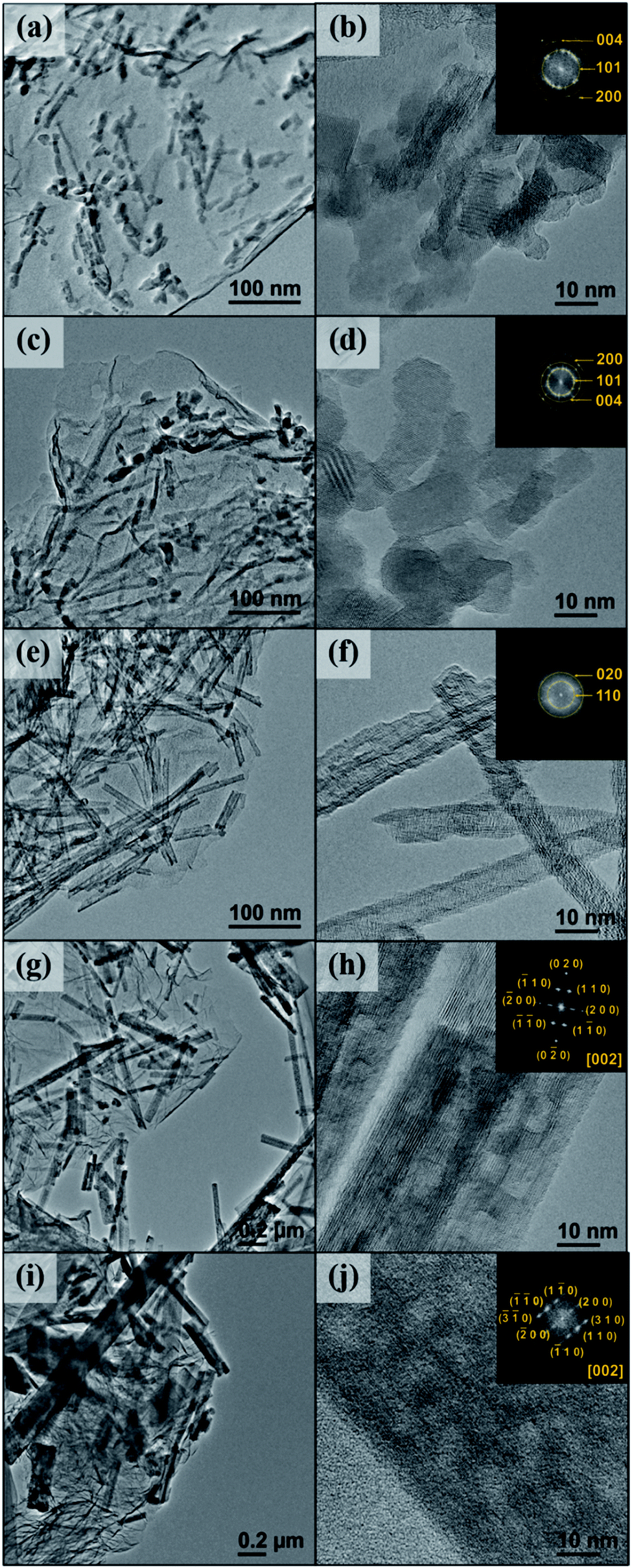 | ||
| Fig. 4 Bright-field TEM and HRTEM images of TiO2 composites on N-doped graphene and the corresponding FFT patterns inserted: (a and b) TNG-3h, (c and d) TNG-6h, (e and f) TNG-9h, (g and h) TNG-12h, and (i and j) TNG-24h. | ||
The HR-TEM images of the TNG composite materials are shown in Fig. 4, where the corresponded fast Fourier transform (FFT) patterns are inserted at the top right corner. The HR-TEM images represent the high-resolution views of TiO2 and FFT patterns which were obtained from the lattice fringe image of as-products. They could be used to determine the phase of synthesized products. From the calculated FFT patterns, the bright spots were due to the presence of highly crystalline TiO2 on the N-doped graphene sheets. These patterns are represented by the weak continuous circle patterns.
In agreement with the XRD study, the diffraction ring of FFT patterns in Fig. 4(b) and (d) revealed that nanoparticles were anatase TiO2 phase. Furthermore, the FFT inset of Fig. 4(f) confirmed that the nanotubes were successfully indexed as the TiO2(B) phase. In Fig. 4(h) and (j), the presence of FFT patterns taken from the TNG-12h and TNG-24h products provided the spot diffraction, which corresponded to the [002] orientation of TiO2(B) nanorods. To further investigate the phase transformation from anatase to TiO2(B), all TNG composites were identified by the STEM-EELS technique, discussed in the next section.
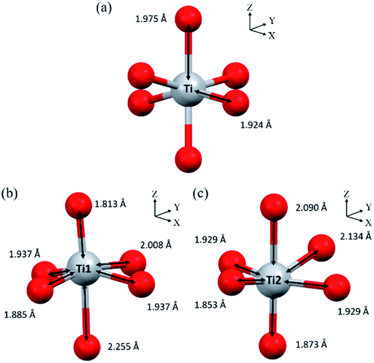
To further investigate the TiO2 structure of TNG composites, EELS spectra were taken from the area of as-prepared TiO2. Fig. 5 shows Ti L2,3-edge spectra taken from nanoparticles-, nanotube-, and nanorod-TiO2 of TNG products. There were two major contributions in L2 and L3 edges. They could be attributed to the crystal field splitting by the 2p core hole spin–orbit coupling into two sub-bands of t2g orbitals (dxy, dxz, and dyz) and eg orbitals (dz2 and dx2−y2) of Ti 3d state in octahedral coordination. The spectra from TNG-3h and TNG-6h showed a typical spectral feature of anatase45 where the eg peak of L3-edge had shoulder at 462 eV. On the other hand, the spectra from TNG-9h, TNG-12h, and TNG-24h clearly showed only one broad peak of eg band at 461 eV with positively skewed distribution, and eg peaks in L2-edge slightly shifted toward lower energies by around 1.5 eV. From the overall spectra, both TiO2 polymorphs represented a similar overall orbital splitting in t2g which related to the point between the oxygen neighbors and their π-type bond, besides the splitting of eg peak showed the major difference which related to the point directly toward the oxygen ligands forming p orbitals. Therefore, the eg band of both polymorphs showed different peaks because the crystal field splitting changed when the configurations of the oxygen ligands were slightly altered in different structures noted as bond lengths and bond angles.50 The primitive octahedral TiO6 unit of anatase and TiO2(b) are shown in Fig. 6. When focusing on the bond angles of O–Ti–O, the large distortion located out of the plane and main axis affected the splitting of eg peak in both phases.
 | ||
| Fig. 5 EELS spectra of Ti L2,3-edges taken from various morphologies of TiO2 in the TNG samples. | ||
 | ||
| Fig. 6 Primitive octahedral TiO6 units in (a) anatase and (b and c) TiO2(B). | ||
Hence, the number of different bond lengths not only contributed to the spectra but also leads to the splitting of eg state. The Ti–O bond lengths of octahedrons in anatase and TiO2(B) are shown in Fig. 6(a, b and c), respectively. In anatase local structure, the two-elongated Ti–O bonds along the z-axis (dz2) were about 1.975 Å, while the four equatorial Ti–O bonds along the x- and y-axis (dx2−y2) with a slightly smaller bond length of 1.924 Å.51 It suggested that the two peaks of eg splitting in L3-edge were obviously displayed in the EELS spectra of anatase. In the case of TiO2(B), two types of Ti4+ atom were occupied in the unit cell denoted as Ti1 and Ti2 in Fig. 6(b and c). It is well known that the crystal structure of TiO2(B) has low symmetry due to the imperfect octahedral unit located inside. Due to the EELS spectra reflect the local symmetry, the several bond length and distorted angle of octahedral TiO6 corresponded to an asymmetric broadening peak at 461.5 eV. Thus, this work is the first report about the novel information of the TiO2(B) EELS spectrum which can be used for an advanced TiO2(B) phase identification.
The model illustration of TNG composite morphology transformation from anatase to TiO2(B) is shown in Fig. 7. Due to the increase of hydrothermal reaction time, the morphology of investigated materials can be varied as nanoparticles, nanosheet, nanotube, and nanorods. As it was mentioned previously, it can be suggested that Ti–O–Ti bonds in the TiO2 precursor were broken to the TiO2 building blocks because OH− ions which came from NaOH solution attacked the former anatase structure. Next, the TiO2 building blocks grew during the hydrothermal reaction. In the case of short reaction time as 3 h, the anatase nanoparticles were attached to N-doped graphene sheets. When the reaction time was increased to 6 h, the small nanoparticles were closed to form nanosheets corresponding to the epitaxial crystal growth along the c-axis. When the reaction time up above 9 h, the exfoliation of the single-layered of Na2Ti6O13 sheets could be promoted in the solution. The interlayer space between the sheets was intercalated by Na+. It can cause the neutralization of negative charge in multi-layered structures of the TiO6 octahedral. Thus, these processes could lead to TiO2(B) formation. In the presence of TNG-9h, the flat nanosheets as well as the curved ones were eventually rolled up and scroll along the b-axis to strain-induced surface free energy changes of the curvature of the nanotube walls.30 Hence, the TiO2(B) nanotubes were observed in TNG-9h.52 When the reaction time was extended to 12 h, the nanosheets roll in further to transform into TiO2(B) nanorods. Finally, the nanorods were still observed in more various sizes at the reaction time of 24 h because of the TiO2(B) crystal growth along with the preferred orientation as well as reducing surface energy of the nanorods.53,54 To explain the reaction process and phase formation of the primary intermediate products, the XRD technique was used to characterize as represented in Fig. S5.† The XRD patterns in Fig S5(a)† of the hydrothermal product indexed as a hydrated form of NaTi3O6(OH)(H2O)2. It can be suggested that OH− and H2O molecules were retained inside the crystal structure because the removal of excess ion and drying processes is not enough. However, this product can be dehydrated to be a tropical Na2Ti6O13 product by DI-water washing and drying in an oven. For the dehydrated mechanism, the water molecules were removed as shown in the eqn (1).55
| 2NaTi3O6(OH)(H2O)2 → Na2Ti6O13 + 5H2O | (1) |
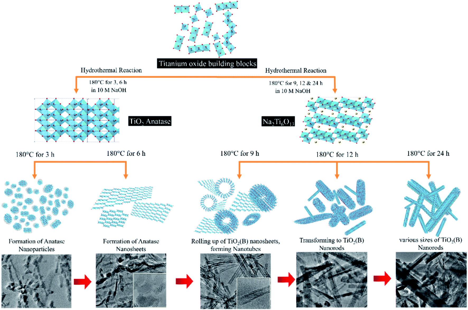 | ||
| Fig. 7 Schematic diagram of TiO2 morphology transformation with the corresponding TEM images according to reaction times of the hydrothermal synthesis. | ||
After the ion-exchange process, the product seems to match with the H2Ti3O7 reference pattern. Thus, the absence of sodium titanate peaks suggests that all the Na+ ions were replaced by H+ ions as confirmed by the XRD results in Fig. S5(b).† The XRD patterns of the final products after heat treatment in Fig. S5(c)† can be indexed to the monoclinic crystal structure of TiO2(B). These results show the phase transformation of titanate products during this procedure.
Besides the remarkable influence of phase composition, the morphology explained above also influenced the electrochemical properties of anode materials.56 To realize the active sites of Li-ion interaction via the charge–discharge process, this work has reported the specific surface areas of synthesized TNG nanocomposites (Table 2). The values were in good agreement with the individual morphology of TiO2. These suggested that nanoparticles of anatase in TNG-3h (240.54 m2 g−1) showed higher surface area than anatase nanosheet in TNG-6h (235.09 m2 g−1) because two-dimensional (2D) was formed by the agglomeration of small anatase nanoparticles. Because of the double-walled surface of nanotube57 TNG-9h (346.53 m2 g−1) consisted of TiO2(B) nanotube possesses a higher surface area than nanorods in TNG-12h (188.66 m2 g−1) and TNG-24h (174.80 m2 g−1) with relatively large size in one dimension of crystal growth. As these results have shown, the effect of high surface areas and unique surface energetics of synthesized materials play a major role in providing the high specific capacity and rates cycle performance.58 Hence, the electrochemical properties of all nanocomposites were examined to gain more quantitative insight.
| Sample | Specific surface area, SBET (m2 g−1) | BET C-constant |
|---|---|---|
| TNG-3h | 240.54 | 68.97 |
| TNG-6h | 235.09 | 75.86 |
| TNG-9h | 346.53 | 53.73 |
| TNG-12h | 188.66 | 78.08 |
| TNG-24h | 174.80 | 62.17 |
The successful quantitative analysis of TiO2 on N-dope graphene is also reflected in the thermal decomposition behavior (TGA curves) as presented in Fig. S6.† The TNG samples were heated in the range of RT-800 °C under air flow (20 ml min−1) with a heating rate of 10 °C min−1. In the initial TGA curves, it is believed to be due to the evaporation of physisorbed water. Then, the remaining oxygen functionalities in N-doped graphene were decomposed in the region of 150–300 °C. Thus, the samples exhibited negligible weight loss in the range of 300–500 °C, which was associated with the removal of more stable nitrogen-doped groups. Obviously, the major weight loss, represented above 500 °C, is most likely due to the pyrolysis of the carbon skeleton. Considering the TGA curved, the weight loss of TNG products was stabilized at temperature upon ∼725 °C. This implied that the remaining weight after the high temperature is TiO2, corresponding to its better thermal stability. From the TGA curves, it can indicate the intrinsic amount of N-doped graphene and titania in the as-prepared TNG products, represented in Table 3.
| Samples | The weight content (wt%) | |
|---|---|---|
| TiO2 | N-doped graphene | |
| TNG-3h | 42.71 | 57.29 |
| TNG-6h | 43.29 | 56.71 |
| TNG-9h | 48.56 | 51.44 |
| TNG-12h | 48.44 | 51.56 |
| TNG-24h | 49.34 | 50.66 |
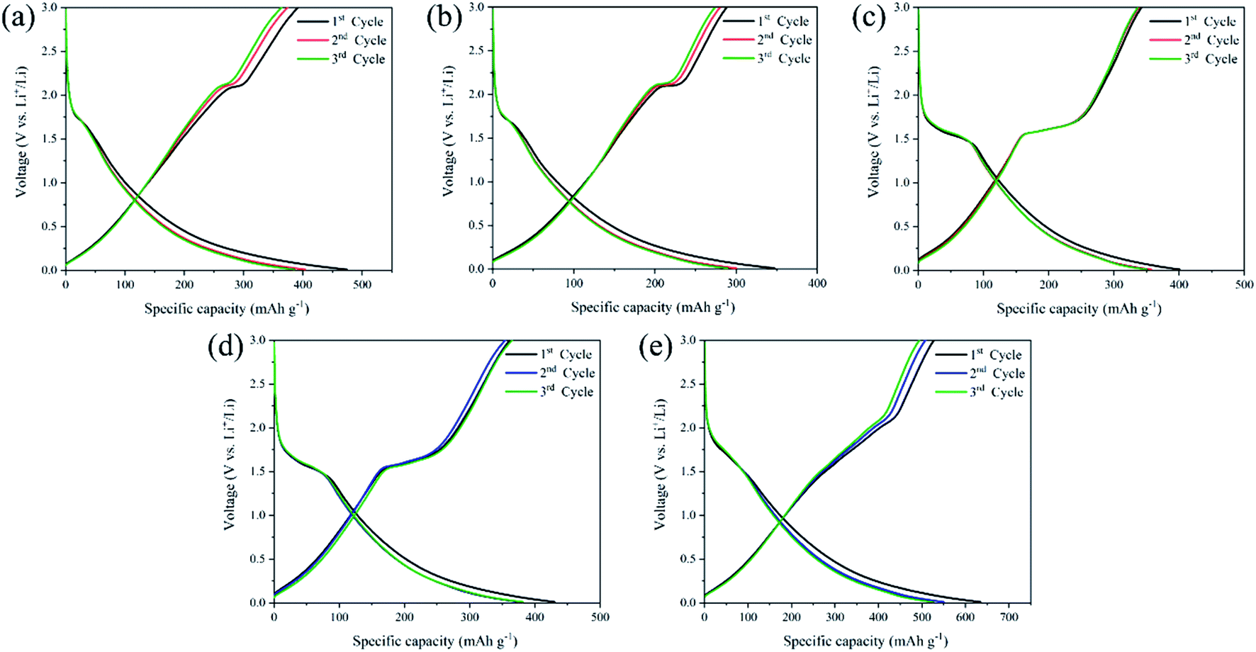
To reveal the correlation of Li-ion insertion/extraction reaction mechanism into the anode structure, the first three cycles galvanostatic charge–discharge (GCD) profiles were measured from TNG nanocomposites ranging from 0.01–3.00 V (vs. Li+/Li) at a current density of 1C rate (1C = 539.5 mA g−1), as illustrated in Fig. 8. The GCD curves demonstrated that the prepared electrodes were initially observed small potential plateaus below ∼0.5 V (vs. Li+/Li) corresponding to Li-ion intercalation into the graphene layers.59–61 The basic reaction mechanism of lithium-ion intercalation in the graphene electrode62 can be written as eqn (2):
| xLi+ + xe− + C3 ↔ LixC3 | (2) |
 | ||
| Fig. 8 GCD profiles at the first three cycles of (a) TNG-3h, (b)TNG-6h, (c)TNG-9h, (d)TNG-12h, and (e)TNG-24h nanocomposites. | ||
In the case of coulombic efficiency, these electrodes exhibited relatively low coulombic efficiency at the initial charging–discharging cycle as represented in Table S2.† It could be due to Li-ion storage at irreversible sites. It can be seen that the presence of the plateau at ∼0.6 V (vs. Li+/Li) is usually assigned to the formation of a solid-electrolyte-interphase (SEI) film.63,64 Because of the large specific surface areas of the N-doped graphene sheet, this could cause one of the reasons for higher irreversible capacity due to SEI formation at the interface with the electrolyte.65,66 Moreover, the decomposition reaction of the electrolytes is suppressed on the TNG surface. This may be attributed to the weak interaction between electrolyte and electrode.67 In the previous characterization, two phases of anatase and TiO2(B) were mainly obtained corresponding to S-shaped voltage curves of GCD in each TNG nanocomposite sample. For these reasons, the GCD profiles were clearly observed in two forms due to the different Li-ion intercalation mechanisms of anatase and TiO2(B). It is well known that the Li-ion insertion/extraction mechanism in TiO2 electrodes can be represented as eqn (3):
| xLi+ + xe− + TiO2 ↔ LixTiO2 | (3) |
The insertion coefficient (x) is related to different TiO2 polymorphs, morphology, and crystallographic orientation. The x in anatase is usually close 0.5.68 TiO2(B) lithiates to x = 0.7–0.8 when lithiation with stable and slow rate cycling.69–71
Obviously, the GCD profiles of TNG-3h and TNG-6h anodes in Fig. 8(a) and (b), respectively, provided the typical characteristic voltage plateaus of anatase with a clear plateau region at ∼1.75 V (vs. Li+/Li).33 This reflects the phase transition from the anatase to the orthorhombic Li0.5TiO2 phase.72 Fig. 8(c–e) shows the GCD profiles of TNG-9h, TNG-12h, and TNG-24h electrodes, respectively. These electrodes obtained the phase composition of TiO2(B). The dominated plateau between 1.4 and 1.6 V (vs. Li/Li+) are corresponding to Li-ion intercalation of TiO2(B).30 It has been reported that the Li-ion intercalation into TiO2(B) is significantly different from anatase because of a pseudo-capacitive process. The Li-ion diffusion process into TiO2(B) is effectively encouraged to store and transport Li-ion along with the structure.56 Amongst the titania polymorphs, much of the argument in the TiO2(B) monoclinic structure has the lowest density crystal framework (3.73 g cm−3) and larger open channels and pores.73
As illustrated in Fig. 9(a), three possible lithium-ion storage sites (A, B, and C sites) and lithium pathways were indicated in the schematic crystal structure of TiO2(B) with a space group of C2/m.74 The framework of the TiO2(B) structure is composed of ReO3 type blocks that consist of distorted TiO6 octahedral sharing the corners of other octahedral.75 “A” storage site act as a Li-ion diffusion pathway and favourable lithium insertion site.76,77 Thus, the pseudo-capacitive channel into TiO2(B), paralleling to the b-axis of its perovskite-like layered structure, propose the possibility of fast Li-ion diffusion pathways.78 Furthermore, the crystal voids in TiO2 polymorphs, anatase (Fig. 9(b)), and TiO2(B) (Fig. 9(c)) affect the amount of Li-ion storages. Therefore, the higher pores with large open channels in TiO2(B) compared to anatase provided the potential to allow Li-ion intercalation into the structure in order to reach an optimum theoretical charge capacity of around 335 mA h g−1. In addition, the first three discharge–charge capacities and coulombic efficiencies of TNG nanocomposite anodes at a current rate of 1C as shown in Table S1,† indicated the diminishing irreversible capacity losses with increasing cycles. Among all preparative TNG composites, the TNG-24h consisted of titania nanorods revealed superior initial specific capacity and delivers excellent first three coulombic efficiencies of 83.12%, 92.30%, and 94.01%, respectively. These could be due to the outstanding pseudocapacitive storage sites of the TiO2(B) and the high-conductivity of N-doped graphene, which is encouraged by electronic conductivity with small resistance.
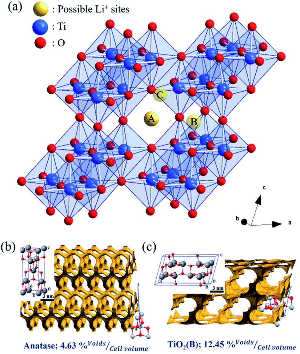 | ||
| Fig. 9 (a)Three possible Li-ion storage sites (yellow atoms) in the schematic crystal structure of TiO2(B) reported by Armstrong et al.79 The blue atoms are Ti atoms and the red one's O atoms. The crystal voids within the structures of (b) anatase and (c) TiO2(B) showing the available voids (yellow shading) and their relative percentage volume. These structures were reproduced from the report of Yothin et al.29 with permission from The Royal Society of Chemistry. | ||
As the interdependent effects of TNG composites that are suitable to individual applications as anode for LIBs, Fig. 10(a) shows the rate capability of the prepared electrodes at various rate current densities within the range of 1C to 50C. It is clearly seen that discharge specific capacity of TNG-24h electrodes at each current rate were observed to have relatively high-capacity retention. Especially, the specific capacity of 200 mA h g−1 was obtained in the TNG-24h electrode at an ultrafast charge state of 50C. Then, the specific capacity was rapidly increased to 500 mA h g−1 without the capacity lost when the current rate returned to the initial rate at 1C, suggesting excellent rate capability as well as good cycle performance. Compared to TNG-3h, TNG-9h, and TNG-12h based composites, the rate capacities were similarly obtained whereas the lowest capacity was obtained from TNG-6h.
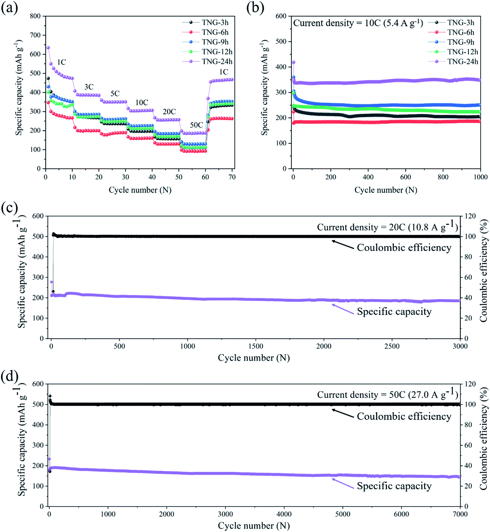 | ||
| Fig. 10 Electrochemical measurements of TNG electrodes: (a) the rate cycle performance at the current density in the range of 1C to 50C. (b) The cycle stability of TNG composites at a current density of 10C for 1000 cycles and (c and d) long-term cycling of TNG-24h electrode at current densities of 20C and 50C, respectively. | ||
To investigate the effect of the TiO2 morphology on LIBs performance, the cycling ability of TNG electrodes with different reaction times was conducted at 10C up to 1000 cycles, as shown in Fig. 10(b). The composite electrodes of TNG-3h, TNG-6h, TNG-9h, TNG-12h, and TNG-24h delivered the reversible capacities of 204.87, 186.39, 250.98, 223.72, and 347.55 mA h g−1, respectively. The highest capacity retention was provided by the nanorods-TiO2(B) in TNG-24h because high crystallinity structure favored the Li-ion intercalation process. The distinctive monoclinic crystal structure of TiO2(B) and its low-density crystal framework, exhibits larger channels and voids, and also a higher specific Li-ion storage capacity as compared to the tetragonal structures of anatase.30 In the case of nanotube-TiO2(B) morphology in the TNG-9h sample, both electronic and Li-ion transport in the composite electrode provided short Li-ion transportation length, facilitating the faster transport of Li-ion during the charge–discharge process. Besides, the double-sided characteristics of the nanotube can promote the active surface for Li-ion intercalation in the charging process. Thus, this behavior affects the specific capacity.
In the case of anatase-TiO2, the nanosheets-TiO2 in TNG-6h were generated from the agglomeration of nanoparticles-TiO2 found in TNG-3h. Because the surface area of nanosheets-TiO2 is lower than nanoparticles-TiO2, the Li-ion diffusion was limited by fewer active sites in the lithiation process, resulting in a lower specific capacity. The nanorods-TiO2(B) was growth on the high surface area of N-doped graphene sheets. Thus, the electron can be transferred easily through the interconnection between TiO2(B) and N-doped graphene. Besides, N-doped graphene in the TNG composites plays an important role in electrochemical performances. The nanosheets of N-doped graphene, which doped nitrogen element possess high electrical conductivity than bare graphene, which served as the interconnected bridges between TiO2 particles. Therefore, the conductivity was increased, while the internal resistance was decreased in LIBs.80,81
To study the long-term cycling capability, the superior current densities of 20C and 50C were applied to TNG-24h electrodes for 3000 and 7000 cycles, respectively. The capacity retention was recorded to 184.36 and 146.15 mA h g−1, respectively. These indicate that the TNG-24h electrode has excellent cycling stability in order to use the ultrafast-charge application. However, the small capacity fading was observed after the 3000th cycle. This could be caused by the cracking behavior corresponded to the extension and contraction of the electrode in the charge–discharge processes.82
The TNG composites with remarkable high-rate and long-life performances have a great potential to use as anodes for the next generation LIBs. Besides, the developed materials preparation technique in this work was facile processes and higher specific capacity and exhibited excellent stability at the ultra-high current density compared with some previous work of TiO2-based materials for LIBs. Although the alloying materials, i.e., Si, Sn, and Ge, have a much higher specific capacity than that commercial graphite and TiO2. However, the use of these elements is hampered by the pulverization of the particles due to the high volumetric change during lithiation and delithiation cycles, which leads to the destabilization of SEI film. These problems result in fast capacity fading and low coulombic efficiency. Comparing to other anodes, organic compounds are also desirable for anode materials, but the poor cycle stability and low power density limit their large-scale application.83 Owning to the major weakness, its capacity at a high current density cannot be maintained due to its poor conductivity, and also the time-/energy-consuming synthetic procedure is very complicated.84 Our report has claimed that these specific capacities, rate performances, and capacity retention are much higher than recent reports, as shown in Table 4. Obviously, the high-battery performance of the present TNG nanocomposites is among the best ones to be the most promising negative electrode materials in the next-generation of advanced LIBs.
| Materials | Year | Specific capacity (mA h g−1) | Current density (mA g−1) | Cycle number | Ref. |
|---|---|---|---|---|---|
| TiO2(B)/N-doped graphene | 2020 | 347.6 | 5400 (10C) | 1000 | This work |
| 184.4 | 10800 (20C) |
3000 | |||
| 146.2 | 27000 (50C) |
7000 | |||
| TiO2(B) nanowires | 2019 | 180 | 100 (0.6C) | 150 | 85 |
| 70 | 10000 (60C) |
10000 |
|||
| TiO2(B) hierarchical tubular structure | 2015 | 160 | 5C | 400 | 86 |
| TiO2(B) nanosheet/rGO | 2014 | 230 | 1C | 1000 | 87 |
| 175 | 20C | 1000 | |||
| TiO2(B) nanowires/N-doped graphene | 2015 | 220.7 | 10C | 1000 | 88 |
| Flower-liked TiO2(B)/Graphene | 2018 | 171 | 5C | 100 | 89 |
| TiO2(B) nanosheet/N-doped graphene | 2017 | 326.4 | 0.6C | 100 | 90 |
| TiO2/rGO | 2017 | 79 | 3400 (20C) | 100 | 91 |
| TiO2 nanorods/rGO | 2019 | 353.6 | 100 | 100 | 92 |
| TiO2/rGO | 2017 | 182 | 500 | 2000 | 93 |
| TiO2 nanotube/Graphene | 2013 | 150 | 4000 | 50 | 94 |
| 80 | 8000 | 2000 | |||
| N-doped TiO2 nanotube/N-doped graphene | 2014 | 169 | 1000 (6C) | — | 95 |
| 80 | 5000 (30C) | — | |||
| Petal-like TiO2 nanosheets | 2014 | 180 | 400 | 96 | |
| TiO2 microparticles/rGO | 2020 | 143 | 1C | 100 | 97 |
| Mesoporous TiO2 spheres/graphene | 2018 | 218 | 0.2C | 100 | 98 |
| Hollow TiO2−x porous microspheres | 2016 | 151 | 190 (1C) | 300 | 99 |
| TiO2/rGO | 2016 | 200 | 100 | 50 | 100 |
Conclusions
TNG composites were successfully synthesized using the hydrothermal method. The effect of reaction durations on the TiO2 phase and morphology transformation has been observed. The nanoparticle-anatase to nanorod-TiO2(B) structures distributed on a highly conductive N-doped graphene network. The as-prepared TNG composites exhibited long cycle stability and high-rate capability when evaluated as anode materials for rechargeable LIBs. Interestingly, the TNG-24h composited with TiO2(B) nanorods delivered a specific capacity of around 350 mA h g−1 at the high current density of 10C for 1000 cycles, due to the high crystal voids and pseudo-capacitive tunnels of TiO2(B) favor to diffuse and transport Li-ion along with the structure. This behaviour provided the best performance as high-capacity anode materials in LIBs. In long term cycling, the TNG-24h displayed excellent cycling stability with a high specific capacity of around 150 mA g−1 during ultrafast-charge of 50C. The synthesized TNG composites are considered promising anode materials for high-performance LIBs.Conflicts of interest
There are no conflicts of interest to declare.Acknowledgements
This work was supported by the Collaborative Research Program of Institute for Chemical Research, Kyoto University (Grant No. 2019-69) and the financial funding by the Office of National Higher Education Science Research and Innovation Policy Council (PMU B) in the Global Partnership Project, the Development and Promotion of Science and Technology Talents Project (DPST), Material Science Research Center and Energy Conservation Fund under the Energy Policy and Planning Office, Ministry of Energy, and Center of Excellence in Materials Science and Technology under the Administration of Materials Science Research Center of Chiang Mai University. The authors would also like to thank the Department of chemistry, Faculty of Science, Chiang Mai University, the National Metal and Materials Technology Center (MTEC) for sample preparation and characterizations. The authors are indebted to thanks Department of Chemistry, Fudan University for battery fabrication and electrochemical measurements, and Kyoto University Microstructural Characterization Platform sponsored by the Ministry of Education, Culture, Sports, Science, and Technology (MEXT), Japan (Grant No. JPMXP09A19KT0019).References
- Y.-K. Sun, S.-T. Myung, B.-C. Park, J. Prakash, I. Belharouak and K. Amine, Nat. Mater., 2009, 8, 320 CrossRef CAS.
- M. Armand and J.-M. Tarascon, Nature, 2008, 451, 652 CrossRef CAS.
- M. S. Whittingham, Chem. Rev., 2004, 104, 4271–4302 CrossRef CAS.
- J. Xie, X. Yang, S. Zhou and D. Wang, ACS Nano, 2011, 5, 9225–9231 CrossRef CAS.
- Z. Wang, Z. Wang, W. Liu, W. Xiao and X. W. (David) Lou, Energy Environ. Sci., 2013, 6, 87–91 RSC.
- A. S. Aricò, P. Bruce, B. Scrosati, J.-M. Tarascon and W. van Schalkwijk, Nat. Mater., 2005, 4, 366–377 CrossRef.
- C. Masarapu, V. Subramanian, H. Zhu and B. Wei, Adv. Funct. Mater., 2009, 19, 1008–1014 CrossRef CAS.
- K. Persson, V. A. Sethuraman, L. J. Hardwick, Y. Hinuma, Y. S. Meng, A. van der Ven, V. Srinivasan, R. Kostecki and G. Ceder, J. Phys. Chem. Lett., 2010, 1, 1176–1180 CrossRef CAS.
- N. A. Kaskhedikar and J. Maier, Adv. Mater., 2009, 21, 2664–2680 CrossRef CAS.
- K. Zhuo, M.-G. Jeong and C.-H. Chung, J. Power Sources, 2013, 244, 601–605 CrossRef CAS.
- M. Ge, J. Rong, X. Fang and C. Zhou, Nano Lett., 2012, 12, 2318–2323 CrossRef CAS.
- I.-S. Hwang, J.-C. Kim, S.-D. Seo, S. Lee, J.-H. Lee and D.-W. Kim, Chem. Commun., 2012, 48, 7061–7063 RSC.
- S. Goriparti, E. Miele, F. De Angelis, E. Di Fabrizio, R. Proietti Zaccaria and C. Capiglia, J. Power Sources, 2014, 257, 421–443 CrossRef CAS.
- Z. Zhang, Y. Du, Q.-C. Wang, J. Xu, Y.-N. Zhou, J. Bao, J. Shen and X. Zhou, Angew. Chem. Int. Ed., 2020, 59, 17504–17510 CrossRef CAS.
- M. Y. Congwei Tan Shipu Xu, J. Wu, S. Chen, Y. Zhao, C. Liu, Y. Zhang, T. Tu, T. Li, P. Gao and H. Peng, Acta Phys. Chim. Sin., 2020, 36, 1908030–1908038 Search PubMed.
- X. Ge, S. Liu, M. Qiao, Y. Du, Y. Li, J. Bao and X. Zhou, Angew. Chem. Int. Ed., 2019, 58, 14578–14583 CrossRef CAS.
- R. Mo, D. Rooney, K. Sun and H. Y. Yang, Nat. Commun., 2017, 8, 13949 CrossRef CAS.
- Y. Zhao, X. Li, B. Yan, D. Li, S. Lawes and X. Sun, J. Power Sources, 2015, 274, 869–884 CrossRef CAS.
- S. K. Tiwari, S. Sahoo, N. Wang and A. Huczko, J. Sci. Adv. Mater. Devices, 2020, 5, 10–29 CrossRef.
- C. Ma, X. Shao and D. Cao, J. Mater. Chem., 2012, 22, 8911–8915 RSC.
- Y. Fang, X. Xu, Y. Du, X. Zhu, X. Zhou and J. Bao, J. Mater. Chem. A, 2018, 6, 11244–11251 RSC.
- Z.-S. Wu, W. Ren, L. Xu, F. Li and H.-M. Cheng, ACS Nano, 2011, 5, 5463–5471 CrossRef CAS.
- H. Wang, C. Zhang, Z. Liu, L. Wang, P. Han, H. Xu, K. Zhang, S. Dong, J. Yao and G. Cui, J. Mater. Chem., 2011, 21, 5430–5434 RSC.
- H. Wang, T. Maiyalagan and X. Wang, ACS Catal., 2012, 2, 781–794 CrossRef CAS.
- H. Xu, L. Ma and Z. Jin, J. Energy Chem., 2018, 27, 146–160 CrossRef.
- Z. Chen, I. Belharouak, Y.-K. Sun and K. Amine, Adv. Funct. Mater., 2013, 23, 959–969 CrossRef CAS.
- Z. Yang, D. Choi, S. Kerisit, K. M. Rosso, D. Wang, J. Zhang, G. Graff and J. Liu, J. Power Sources, 2009, 192, 588–598 CrossRef CAS.
- M. Zukalová, M. Kalbáč, L. Kavan, I. Exnar and M. Graetzel, Chem. Mater., 2005, 17, 1248–1255 CrossRef.
- Y. Chimupala, P. Junploy, T. Hardcastle, A. Westwood, A. Scott, B. Johnson and R. Brydson, J. Mater. Chem. A, 2016, 4, 5685–5699 RSC.
- A. G. Dylla, G. Henkelman and K. J. Stevenson, Acc. Chem. Res., 2013, 46, 1104–1112 CrossRef CAS.
- F. T. Wagner, B. Lakshmanan and M. F. Mathias, J. Phys. Chem. Lett., 2010, 1, 2204–2219 CrossRef CAS.
- Y. Chimupala, G. Hyett, R. Simpson, R. Mitchell, R. Douthwaite, S. J. Milne and R. D. Brydson, RSC Adv., 2014, 4, 48507–48517 RSC.
- K. Li, B. Li, J. Wu, F. Kang, J. K. Kim and T. Y. Zhang, ACS Appl. Mater. Interfaces, 2017, 9, 35917–35926 CrossRef CAS.
- T. Autthawong, B. Chayasombat, V. Laokawee, N. Jarulertwathana, T. Masuda and T. Sarakonsri, Solid State Phenom., 2018, 283, 37–45 Search PubMed.
- T. Autthawong, O. Namsar, A. Yu and T. Sarakonsri, J. Mater. Sci. Mater. Electron., 2020, 31, 9126–9132 CrossRef CAS.
- F. T. Johra, J. W. Lee and W. G. Jung, J. Ind. Eng. Chem., 2014, 20, 2883–2887 CrossRef CAS.
- J. Xie, G. Wang, Y. Huo, S. Zhang, G. Cao and X. Zhao, Electrochim. Acta, 2014, 135, 94–100 CrossRef CAS.
- Z. Lin, G. Waller, Y. Liu, M. Liu and C. Wong, Adv. Energy Mater., 2012, 2, 884–888 CrossRef CAS.
- D. Cai, S. Wang, P. Lian, X. Zhu, D. Li, W. Yang and H. Wang, Electrochim. Acta, 2013, 90, 492–497 CrossRef CAS.
- H. Wang, C. Zhang, Z. Liu, L. Wang, P. Han, H. Xu, K. Zhang, S. Dong, J. Yao and G. Cui, J. Mater. Chem., 2011, 21, 5430–5434 RSC.
- D. Wei, Y. Liu, Y. Wang, H. Zhang, L. Huang and G. Yu, Nano Lett., 2009, 5, 1752–1758 CrossRef.
- J. J. Palacios and J. Fernandez-Rossier, Phys. Rev. B: Condens. Matter Mater. Phys., 2008, 77, 195428 CrossRef.
- H. L. Lord, W. Zhan and J. Pawliszyn, in Comprehensive Sampling and Sample Preparation, 2012, vol. 2, pp. 677–697 Search PubMed.
- Q. Liu, Z. Pu, C. Tang, A. M. Asiri, A. H. Qusti, A. O. Al-youbi and X. Sun, Electrochem. Commun., 2013, 36, 57–61 CrossRef CAS.
- J. F. Dai, G. J. Wang, L. Ma and C. K. Wu, Rev. Adv. Mater. Sci., 2015, 40, 60–71 CAS.
- N. Jarulertwathana, V. Laokawee, W. Susingrat, S.-J. Hwang and T. Sarakonsri, J. Mater. Sci. Mater. Electron., 2017, 28, 18994–19002 CrossRef CAS.
- Z. Sheng, L. Shao, J. Chen, W. Bao, F. Wang and X. Xia, ACS Nano, 2011, 5, 4350–4358 CrossRef CAS.
- T. Promanan and T. Sarakonsri, Rev. Adv. Mater. Sci., 2017, 52, 107–112 CAS.
- L. Stobinski, B. Lesiak, A. Malolepszy, M. Mazurkiewicz, B. Mierzwa, J. Zemek, P. Jiricek and I. Bieloshapka, J. Electron Spectrosc. Relat. Phenom., 2014, 195, 145–154 CrossRef CAS.
- U. Diebold, Surf. Sci. Rep., 2003, 48, 53–229 CrossRef CAS.
- B. Wen, Q. Hao, W.-J. Yin, L. Zhang, Z. Wang, T. Wang, C. Zhou, A. Selloni, X. Yang and L.-M. Liu, Phys. Chem. Chem. Phys., 2018, 20, 17658–17665 RSC.
- M.-J. Li, Z.-Y. Chi and Y.-C. Wu, J. Am. Ceram. Soc., 2012, 8, 1–8 Search PubMed.
- C. W. Lai, S. Bee Abd Hamid, T. L. Tan and W. H. Lee, J. Nanomater., 2015, 2015, 145360 Search PubMed.
- Q. Chen and L. Peng, Int. J. Nanotechnol., 2007, 4, 44–65 CrossRef CAS.
- Y. Chimupala and R. Drummond-Brydson, Solid State Phenom., 2018, 283, 23–36 Search PubMed.
- L. Kavan, M. Kalbáč, M. Zukalová, I. Exnar, V. Lorenzen, R. Nesper and M. Graetzel, Chem. Mater., 2004, 16, 477–485 CrossRef CAS.
- S. Li, J. Chen, F. Zheng, Y. Li and F. Huang, Nanoscale, 2013, 5, 12150–12155 RSC.
- P. G. Bruce, B. Scrosati and J.-M. Tarascon, Angew. Chem. Int. Ed., 2008, 47, 2930–2946 CrossRef CAS.
- K. Ji, J. Han, A. Hirata, T. Fujita, Y. Shen, S. Ning, P. Liu, H. Kashani, Y. Tian, Y. Ito, J. Fujita and Y. Oyama, Nat. Commun., 2019, 10, 275 CrossRef.
- R. Raccichini, A. Varzi, D. Wei and S. Passerini, Adv. Mater., 2017, 29, 1603421 CrossRef.
- F. Yao, F. Güneş, H. Q. Ta, S. M. Lee, S. J. Chae, K. Y. Sheem, C. S. Cojocaru, S. S. Xie and Y. H. Lee, J. Am. Chem. Soc., 2012, 134, 8646–8654 CrossRef CAS.
- L. Tian, Q. Zhuang, J. Li, Y. Shi, J. Chen, F. Lu and S. Sun, Chin. Sci. Bull., 2011, 56, 3204 CrossRef CAS.
- P. Guo, H. Song and X. Chen, Electrochem. Commun., 2009, 11, 1320–1324 CrossRef CAS.
- X.-B. Cheng, C. Yan, X. Chen, C. Guan, J.-Q. Huang, H.-J. Peng, R. Zhang, S.-T. Yang and Q. Zhang, Chem, 2017, 2, 258–270 CAS.
- X. Li, D. Geng, Y. Zhang, X. Meng, R. Li and X. Sun, Electrochem. Commun., 2011, 13, 822–825 CrossRef CAS.
- J. Hui, M. Burgess, J. Zhang and J. Rodríguez-López, ACS Nano, 2016, 10, 4248–4257 CrossRef CAS.
- H. Huang, W. K. Zhang, X. P. Gan, C. Wang and L. Zhang, Mater. Lett., 2007, 61, 296–299 CrossRef CAS.
- L. Kavan, J. Electrochem. Soc., 1996, 143, 394 CrossRef CAS.
- A. R. Armstrong, G. Armstrong, J. Canales, R. García and P. G. Bruce, Adv. Mater., 2005, 17, 862–865 CrossRef CAS.
- M. Inaba, Y. Oba, F. Niina, Y. Murota, Y. Ogino, A. Tasaka and K. Hirota, J. Power Sources, 2009, 189, 580–584 CrossRef CAS.
- A. R. Armstrong, G. Armstrong, J. Canales and P. G. Bruce, Angew. Chem. Int. Ed., 2004, 43, 2286–2288 CrossRef CAS.
- M. Wagemaker, R. van de Krol, A. P. M. Kentgens, A. A. van Well and F. M. Mulder, J. Am. Chem. Soc., 2001, 123, 11454–11461 CrossRef CAS.
- M. Søndergaard, Y. Shen, A. Mamakhel, M. Marinaro, M. Wohlfahrt-Mehrens, K. Wonsyld, S. Dahl and B. B. Iversen, Chem. Mater., 2015, 27, 119–126 CrossRef.
- Y. Harada, K. Hoshina, H. Inagaki and N. Takami, Electrochim. Acta, 2013, 112, 310–317 CrossRef CAS.
- T. Okumura, T. Fukutsuka, A. Yanagihara, Y. Orikasa, H. Arai, Z. Ogumi and Y. Uchimoto, J. Mater. Chem., 2011, 21, 15369–15377 RSC.
- A. R. Armstrong, C. Arrouvel, V. Gentili, S. C. Parker, M. S. Islam and P. G. Bruce, Chem. Mater., 2010, 22, 6426–6432 CrossRef CAS.
- C. Arrouvel, S. C. Parker and M. S. Islam, Chem. Mater., 2009, 21, 4778–4783 CrossRef CAS.
- Y. Zhang, Q. Fu, Q. Xu, X. Yan, R. Zhang, Z. Guo, F. Du, Y. Wei, D. Zhang and G. Chen, Nanoscale, 2015, 7, 12215–12224 RSC.
- A. R. Armstrong, C. Arrouvel, V. Gentili, S. C. Parker, M. S. Islam and P. G. Bruce, Chem. Mater., 2010, 22, 6426–6432 CrossRef CAS.
- C. Zha, D. He, J. Zou, L. Shen, X. Zhang, Y. Wang, H. H. Kung and N. Bao, J. Mater. Chem. A, 2014, 2, 16931–16938 RSC.
- B. Wang, J. Jin, X. Hong, S. Gu, J. Guo and Z. Wen, J. Mater. Chem. A, 2017, 5, 13430–13438 RSC.
- D. He, K. Cheng, T. Peng, M. Pan and S. Mu, J. Mater. Chem. A, 2013, 1, 2126–2132 RSC.
- C. Luo, O. Borodin, X. Ji, S. Hou, K. J. Gaskell, X. Fan, J. Chen, T. Deng, R. Wang, J. Jiang and C. Wang, Proc. Natl. Acad. Sci., 2018, 115, 2004 CrossRef CAS LP – 2009.
- B. Häupler, A. Wild and U. S. Schubert, Adv. Energy Mater., 2015, 5, 1402034 CrossRef.
- Y. Wang and J. Zhang, Ionics, 2020, 26, 1159–1164 CrossRef CAS.
- H. Hu, L. Yu, X. Gao, Z. Lin and X. W. Lou, Energy Environ. Sci., 2015, 8, 1480–1483 RSC.
- V. Etacheri, J. E. Yourey and B. M. Bartlett, ACS Nano, 2014, 8, 1491–1499 CrossRef CAS.
- X. Yan, Y. Li, M. Li, Y. Jin, F. Du, G. Chen and Y. Wei, J. Mater. Chem. A, 2015, 3, 4180–4187 RSC.
- J. F. Wang, J. J. Zhang and D. N. He, Nano-Struct. Nano-Objects, 2018, 15, 216–223 CrossRef CAS.
- Z. Han, J. Peng, L. Liu, G. Wang, F. Yu and X. Guo, RSC Adv., 2017, 7, 7864–7869 RSC.
- L. Yan, J. Yu and H. Luo, Appl. Mater. Today, 2017, 8, 31–34 CrossRef.
- Y. Ma, Y. Li, D. Li, Y. Liu and J. Zhang, J. Alloys Compd., 2019, 771, 885–891 CrossRef CAS.
- J. Li, J. Huang, J. Li, L. Cao, H. Qi, Y. Cheng, Q. Xi and H. Dang, J. Alloys Compd., 2017, 727, 998–1005 CrossRef CAS.
- J. Wang, Y. Zhou, B. Xiong, Y. Zhao, X. Huang and Z. Shao, Electrochim. Acta, 2013, 88, 847–857 CrossRef CAS.
- Y. Li, Z. Wang and X. J. Lv, J. Mater. Chem. A, 2014, 2, 15473–15479 RSC.
- F. Wu, Z. Wang, X. Li and H. Guo, Ceram. Int., 2014, 40, 16805–16810 CrossRef CAS.
- S. A. D. R. Madhusanka, R. D. L. Sandaruwan, M. M. Athar, M. Zaib and H. M. M. Munasinghe, Int. J. Electrochem. Sci., 2020, 15, 2792–2805 CrossRef CAS.
- T. Du, W. Zhang, H. Peng and G. Jain, Int. J. Electrochem. Sci., 2018, 13, 6229–6235 CrossRef CAS.
- C. Wang, F. Wang, Y. Zhao, Y. Li, Q. Yue, Y. Liu, Y. Liu, A. A. Elzatahry, A. Al-Enizi, Y. Wu, Y. Deng and D. Zhao, Nano Res., 2016, 9, 165–173 CrossRef CAS.
- H.-K. Kim, D. Mhamane, M.-S. Kim, H.-K. Roh, V. Aravindan, S. Madhavi, K. C. Roh and K.-B. Kim, J. Power Sources, 2016, 327, 171–177 CrossRef CAS.
Footnote |
| † Electronic supplementary information (ESI) available. See DOI: 10.1039/d0ra07733j |
| This journal is © The Royal Society of Chemistry 2020 |