 Open Access Article
First-principles calculations of an asymmetric MoO2/graphene nanocomposite as the anode material for lithium-ion batteries†
Qiuyu Zhang ,
Dongyang Zhu,
Xiaowei Li
 * and
Yihe Zhang
National Laboratory of Mineral Materials, Beijing Key Laboratory of Materials Utilization of Nonmetallic Minerals and Solid Wastes, School of Materials Science and Technology, China University of Geosciences (Beijing), Beijing 100083, China. E-mail: lixiaowei@cugb.edu.cn
First published on 7th December 2020
Abstract
Previous work on the synthesis and preparation of MoO2/graphene nanocomposites (MoO2/G) indicates that MoO2/G is a good anode material for lithium-ion batteries (LIBS). In this work, we used larger super-cells than those used previously to theoretically construct an asymmetric MoO2/G nanocomposite with smaller lattice mismatch. We then calculated the structural, electronic and Li atom diffusion properties of MoO2/G using first-principles calculations based on density functional theory. The results show that asymmetric MoO2/G has metallic properties, good stability and a low Li atom diffusion barrier because of the charge transfer induced by van der Waals interactions. The Li diffusion barriers in the interlayer of MoO2/G are in the range of 0.02–0.29 eV, depending on the relative positions of the Li atom and the MoO2 and the C atoms in the graphene layer. The Li diffusion barriers on the outside layers of the MoO2/G nanocomposite are smaller than those of its pristine materials (MoO2 and graphene). These results are consistent with experimental results. The adsorption of Li atoms in the interlayer of the nanocomposite further promotes the adsorption of Li atoms on the outside sites of the MoO2 layer. Hence, the specific capacity of the MoO2/G nanocomposite is larger than 1682 mA h g−1. These properties all indicate that MoO2/G is a good anode material for LIBS.
1. Introduction
Lithium-ion batteries (LIBS) are widely used as portable batteries in mobile phones, notebook computers, and electric vehicles, due to their high energy density, long life and good cycle performance.1–4 The performance of LIBS is largely determined by the electrode materials used; traditional commercial LIBS mainly use lower-cost graphene as the anode material. However, its theoretical capacity is only 372 mA h g−1,5,6 which cannot meet the high-capacity demand of lithium-ion batteries. In order to obtain a higher lithium storage capacity, transition metal oxides, such as TiO2, Fe3O4, Co3O4, MoO2, Fe2O3, SnO2 and NiO, may be used as they have high theoretical capacities, rate performance, may be recycled and are low cost. Of these, MoO2 stands out because of its good conductivity and high theoretical capacity of 838 mA h g−1, which is about 2.3 times that of graphene.7 However, MoO2 also has its significant disadvantages, for example, it experiences significant volume expansion and severe particle agglomeration during lithium atom insertion and extraction. This causes pulverization of the MoO2 powder, resulting in detachment of the electrode material and a rapid drop in capacity.8 There are two methods that can be used to improve the above problems. One is to prepare nanostructured MoO2, such as nanoparticles, nanospheres, nanobelts or nanowires.9–11 Compared to the bulk material, the nanomaterials have a larger ion contact area, are able to achieve high specific capacities and have shorter diffusion paths, which facilitates rapid diffusion and a high utilization of lithium ions. Another method is to form a composite of MoO2 and carbon, thereby slowing or solving the problem of volume expansion caused by lithium ion insertion and extraction.7Graphene is a two-dimensional planar sheet that exhibits sp2 bonding, has a specific atomic thickness, a high specific surface area, good room temperature carrier mobility and thermal conductivity. Therefore, graphene is a very suitable material for the formation of composites of MoO2 and carbon. In recent years, the preparation of MoO2/graphene (MoO2/G) nanocomposites and their properties have been investigated. Akkisetty Bhaskar12 used non-toxic citric acid and polyethylene glycol to reduce graphene oxide and synthesize a MoO2/G composite under conditions limiting graphene and MoO2 formation, thereby increasing the storage capacity and conductivity of the lithium atoms. Tang4 used ascorbic acid as a reducing agent to form MoO2 nanoparticles on graphene sheets via a two-step hydrothermal calcination to form a MoO2/G nanocomposite. The MoO2 particles were dispersed on the graphene to change the MoO2/G composite into an amorphous structure, thereby expanding the lithium atom capacity, reducing the charge transfer resistance and the aggregation of the graphene sheets.
Theoretical studies can observe and analyze the stability and electrochemical properties of materials, such as the lithium adsorption capacity, the stability and the electrical conductivity of the material, from the atomic level. Recently, Jiachen Ma13 used a smaller super-cell to theoretically construct a MoO2/G nanocomposite. It was found that the C–C bond length in the structure changed too much and the tensile strain was as high as 12%. However, these properties are difficult to achieve in an actual preparation process. Thus, in this work, via first-principles calculations based on density functional theory (DFT), we chose larger super-cells of MoO2 and graphene to construct a MoO2/G nanocomposite with smaller lattice mismatch. We then studied the geometric stability, electronic properties, and the Li atom adsorption and diffusion properties of the MoO2/G nanocomposite.
2. Calculation methods
All the calculations were carried out using DFT as implemented in the Vienna ab initio simulation package (VASP).14 The electronic exchange-correlation interaction was treated using the generalized gradient approximation (GGA) and the Perdew–Burke–Ernzerhof (PBE) functional.15 The electronic wave function was extended in the plane wave basis set and used a kinetic energy cutoff of 500 eV. K-point sampling in the Brillouin area used the Monkhorst–Pack method. The minimum density of the point was 2π × 0.04 Å−1. The convergences of energy and force were set as 1 × 10⁻⁵ eV, 0.04 eV Å−1. In the two-dimensional structural model, a 15 Å vacuum layer was placed in the non-periodic direction to ensure that there was no interaction between the periodic mirrors in this direction. To study the diffusion of Li in the nanocomposite, the nudged elastic band (NEB) method for determining the minimum energy path and energy barrier was implemented in VASP.163. Results and discussion
3.1 Structure
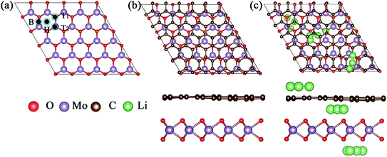
Because of the different lattice parameters of MoO2 and graphene, we constructed the asymmetric MoO2/G nanocomposite using a 6 × 6 graphene super-cell to match a 5 × 5 MoO2 super-cell. After structural optimization without any constraint, we found that the lattice mismatch was only 0.74%. As shown in Fig. 1a, we chose to assess four nanocomposites formed by varying the positions of the C atoms in graphene relative to the MoO2 layer. These nanocomposites were named T1, T2, H and B and describe the situation where one C atom in graphene is located directly above either the O atom, the Mo atom, a hollow site or a bridge site of MoO2, respectively. In order to determine the most stable structure, we calculated the binding energies of the four structures. The binding energy Eb was calculated using the following formula:17| Eb = (EMoO2 + EG − EMoO2/G) |
The calculated binding energies of nanocomposites T1, T2, H and B are 0.485, 0.503, 0.536, and 0.502 eV, respectively. Thus, we find that nanocomposite H is the most stable structure, the optimized structure of which is shown in Fig. 1b. The top view of the MoO2/G nanocomposite presents a hexagonal structure and the side view shows that the C atoms in the graphene layer are not strictly in plane. The distance between the graphene and MoO2 layers varies depending by which MoO2 site the C atom in graphene is located. The smallest distance is about 2.768 Å corresponding to the C atom located on the hollow site of MoO2, while the largest distance is about 3.111 Å corresponding to the C atom located on top of the O atom in MoO2. For the most stable MoO2/G nanocomposite, the calculated O–Mo bond length, O–O distance and O–Mo–O bond angle were about 2.068–2.070 Å, 2.424–2.906 Å, and 71.635–89.194°, which are slightly different from the results obtained for pristine MoO2 (2.05 Å, 2.47 Å and 87.4°).18,19 The calculated C–C bond length and C–C–C bond angle were about 1.395–1.404 Å and 119.87–120.135°, which are almost no different from the results seen in pristine graphene (1.426 Å and 120°). This is because of the unmatched lattice parameters and the interaction between graphene and MoO2 during the construction of the nanocomposite.
3.2 Adsorption properties
The adsorption capacity is one of the main properties used to evaluate the performance of lithium electrode materials. In order to obtain the adsorption properties of Li atoms at different sites, we calculated the adsorption energy (Ead) which is defined as:20| Ead = (EMoO2/G+nLi − EMoO2/G − nELi)/n |
For a low Li adsorption scenario, we model one Li adsorption in one super-cell. There are three adsorption layers, namely the interlayer between MoO2 and graphene (MoO2/Li/G), the outside of the MoO2 layer (Li/MoO2/G) and the outside of the graphene layer (MoO2/G/Li). Considering that the adsorption energy of Li on MoO2 is larger than that on graphene, Li is prone to adsorb on the surface of the MoO2 layer in the MoO2/G interlayer. For the adsorption on the surface of MoO2, on both the outside and the interlayer, four kinds of adsorption sites are considered. These are one hollow site, two top sites and one bridge site. For the adsorption on the outside of graphene, there are three adsorption sites, the hollow site of the carbon ring, on top of a C atom and on a bridge site of a C–C bond. The possible adsorption sites are shown in Fig. 1c.
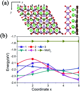
The more negative the adsorption energy, the more stable the structure is. The calculated adsorption energies are tabulated in Table 1. Of the three adsorption layers, the interlayer adsorption is more favorable. The absolute values of the adsorption energies follow the following trend MoO2/Li/G > Li/MoO2/G > MoO2/G/Li. However, the most stable adsorption site for different layers is the hollow site of a MoO2 or graphene carbon ring. It is worth noting that the Li atom adsorbed on the bridge site will move to its nearest hollow site after structural optimization. The calculated adsorption energies of MoO2/Li/G are in the range of −2.358 to −2.040 eV, depending on the relative positions of the C atoms and MoO2, which meets the requirements of an anode material for Li-ion batteries.21 As shown in Fig. 2, when one Li atom is adsorbed on pristine MoO2 the adsorption energy is −1.77 eV, which is larger than the adsorption energies of a Li atom in the interlayer. Therefore, the MoO2/G nanocomposite is conducive to the adsorption of Li atoms. Unexpectedly, when a Li atom is adsorbed on the outside of the graphene layer (the MoO2/G/Li structure), the calculated adsorption energy is negative, which is opposite to that of pristine graphene. The calculated adsorption energy of one Li on pristine graphene is 0.73 eV, which is slightly higher than the result reported by Das (0.71 eV).22 To analyze the mechanisms giving rise to the adsorption energy, we calculated the adsorption energy of a Li atom on pristine graphene using a lattice parameter similar to the nanocomposite. The calculated result demonstrates that the adsorption energy is also positive. So, we can conclude that van der Waals interactions between MoO2 and graphene will promote the adsorption of Li atoms on the surface of graphene. Additionally, the adsorption of a Li atom on the outside of the MoO2/G nanocomposite slightly reduces the interlayer distance, as shown in Table 1. Moreover, compared with the results found for the symmetric MoO2/G nanocomposites constructed by Ma,13 the asymmetric structure is more favorable for the adsorption of Li atoms on the surface of graphene. To further verify the adsorption performance of Li atoms on MoO2/G, a HSE06 functional was used to calculate the adsorption energies of one Li atom at the two outside sites and at the MoO2/G interlayer. For the most favorable adsorption sites at the two outside sites and at the interlayer, the calculated adsorption energies are −1.447, −2.171 and −0.049 eV, respectively. This result further demonstrates that the asymmetric structure of MoO2/G with smaller lattice mismatch will improve the adsorption performance of the material with respect to Li atoms.
| Structure | Ead (eV) | d (Å) |
|---|---|---|
| MoO2/G | — | 2.768–3.111 |
| MoO2/Li/G | −2.358 to −2.040 | 2.708–3.151 |
| Li/MoO2/G | −1.913 to −1.917 | 2.745–3.101 |
| MoO2/G/Li | −1.013 to −0.989 | 2.711–3.083 |
Due to the lattice mismatch between MoO2 and graphene, we calculated the adsorption energies of one Li atom at different hollow sites of the MoO2 in the interlayer. As shown in Fig. 2a, there are 25 (5 × 5) hollow MoO2 adsorption sites in one supercell, namely coordinates 1 to 5 along the x and y axis. The calculated adsorption energies are shown in Fig. 2b. We can see that a Li atom has a larger adsorption energy (−2.358 eV) at the site where the MoO2 ring overlaps with the carbon ring of graphene (coordinate (5,5) in Fig. 2a), while it has smaller adsorption energy (−2.040 eV) at the site where the MoO2 ring overlaps with the C atom of graphene (coordinate (2,2) in Fig. 2a). We also find that the lower the adsorption energy of the Li atom, the further away the C atom is from the center of the MoO2 ring, this result is consistent with that of the mechanical analysis.
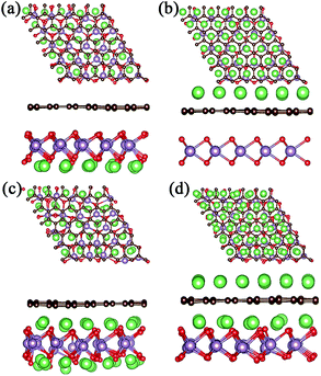
For a high Li atom adsorption scenario, we calculated multi-layer adsorptions as shown in Fig. 3 and Fig. 4. Due to larger adsorption energies in the interlayer, the first-layer of Li atoms are adsorbed in the MoO2/G interlayer with a calculated average Li atom adsorption energy of −1.256 eV. In order to verify the effect of interlayer adsorption on the adsorption at MoO2 and graphene outside sites, we undertook the following experiments. If we only adsorbed one layer of Li atoms on the outside of the MoO2 layer, the calculated average adsorption energy was −0.785 eV, as shown in Fig. 3a. This is obviously different from the value obtained for the second-layer Li adsorption on the outside of the MoO2 layer (−1.426 eV), as shown in Fig. 3c. When we adsorbed only one layer of Li atoms on the outside of the graphene layer, the calculated average adsorption energy was 0.374 eV, as shown in Fig. 3b. This is slightly larger than the value obtained for the second-layer Li adsorption on the outside of the graphene layer (0.323 eV), as shown in Fig. 3d. Therefore, it can be concluded that the interlayer adsorption of Li atoms will largely promote the adsorption of Li atoms on the outside sites of both the MoO2 layer and the graphene layer.
In order to further verify the stability of Li adsorption on the outside and in the interlayer of the MoO2/G nanocomposite, ab initio molecular dynamics (AIMD) simulations were carried out for the adsorption of three layers at 300 K, and the results are shown in Fig. S1.† It can be seen that after 5 ps Li atoms were adsorbed well on both the surface of the MoO2 layer and in the interlayer of the MoO2/G nanocomposite, and that only some of the Li atoms on the outside sites of the graphene layer were separated from their original positions. The AIMD results are consistent with the adsorption energies calculated above. More Li atoms on the outside sites of the graphene layer will be clustered because of the positive adsorption energy.
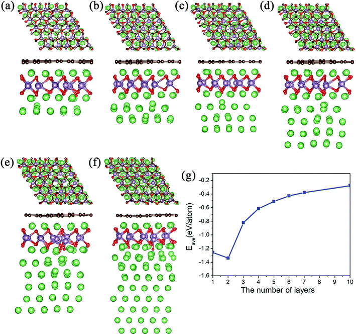
Meanwhile, we tested the specific capacity of the MoO2/G nanocomposite, since the average adsorption energy of the Li atoms on the outside sites of the MoO2 layer is negative, we preferred to adsorb multiple layers of Li atoms on the outside sites of the MoO2 layer. The geometric structures observed following the adsorption of 3 to 10 layers are shown in Fig. 4a–f. Each layer contains 25 Li atoms and it was found that the absolute value of the average adsorption energy decreased as the number of layers increased, as shown in Fig. 4g. The adsorption energy associated with the adsorption of ten layers of Li atoms is −0.278 eV, which means that more Li atoms could be adsorbed on the outside sites of the MoO2 layer. So, we can conclude that the MoO2/G nanocomposite can increase the specific capacity of Li atoms.
We also calculated the theoretical gravimetric capacity of MoO2/G using the formula: C = nF/(MMoO2/G + nMLi),23 where n is the number of adsorbed Li atoms and F is the Faraday constant (26![[thin space (1/6-em)]](https://www.rsc.org/images/entities/char_2009.gif) 801 mA h mol−1), MMoO2/G and MLi are the mole weights of the MoO2/G nanocomposite and Li atom. When adsorbing nine layers of Li atoms, the estimated total capacity is 1682 mA h g−1. Because the adsorption energy for nine layers of Li atoms is negative, we can conclude that the specific capacity of the MoO2/G nanocomposite will be larger than 1682 mAhg−1. Overall, the MoO2/G nanocomposite outperforms graphene and MoO2 as an anode material for LIBs because of its higher capacity.
801 mA h mol−1), MMoO2/G and MLi are the mole weights of the MoO2/G nanocomposite and Li atom. When adsorbing nine layers of Li atoms, the estimated total capacity is 1682 mA h g−1. Because the adsorption energy for nine layers of Li atoms is negative, we can conclude that the specific capacity of the MoO2/G nanocomposite will be larger than 1682 mAhg−1. Overall, the MoO2/G nanocomposite outperforms graphene and MoO2 as an anode material for LIBs because of its higher capacity.
3.3 Electronic properties
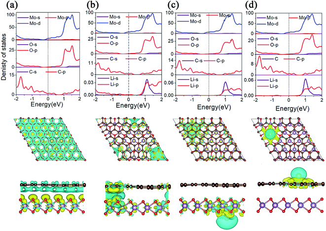
The conductivity of LIBS plays an important role in the evaluation of electrode materials. In order to gain a deep understanding of the electronic properties, we calculated the projected density of states (PDOS) and the charge density difference of MoO2/G before and after Li adsorption, as shown in Fig. 5. As shown in Fig. 5a, because the energy bands of the MoO2/G nanocomposite shift due to electron transfer from graphene to MoO2, the d orbital of the Mo atom in MoO2 and the p orbital of the C atom in graphene pass through the Fermi energy level. By comparing the PDOS of MoO2/G before and after Li adsorption, it is found that MoO2/G still retains its metallic properties, and that the d orbital of the Mo atom does not change much at the Fermi energy level. Thus, the MoO2/G nanocomposite, as an anode material for LIBS, has metallic properties and good conductivity. Conversely, when one Li atom is adsorbed in the interlayer, as shown in Fig. 5b, Li transfers charge with both the MoO2 and graphene layers. Bader charge analysis shows that 0.867|e| is donated to MoO2 and graphene. While one Li atom is adsorbed on the outside sites of the MoO2 or graphene layers, as shown in Fig. 5c and d, charge transfer only occurs between the Li atom and either the MoO2 or graphene layers. Bader charge analysis shows that 0.900|e| or 0.897|e| is donated to MoO2 or graphene, respectively.3.4 Diffusion properties
The charge/discharge rate of LIBS is closely related to the diffusion performance of Li atoms in the anode material. Therefore, we calculated the diffusion properties of Li atoms on the surface of MoO2 and the MoO2/G nanocomposite. The Li atom diffusion paths are shown in Fig. 6. The calculation uses the NEB method to insert three coordinates between the two nearest adjacent stable Li atom adsorption sites. As shown in Fig. 6a–c, the diffusion energy barriers for a Li atom on the surface of pristine MoO2 and on the outside sites of the MoO2/G nanocomposite are about 0.17 eV, 0.16 eV and 0.33 eV, respectively. So, the diffusion energy barriers for a Li atom on the surfaces of the MoO2/G nanocomposite are smaller than those on the pristine materials (the energy barrier of pristine graphene is 0.37 eV (ref. 6 and 22)). However, when a Li atom diffuses in the MoO2/G interlayer, the energy barrier is no longer periodic and depends on the relative positions of the Li atom and MoO2 and the C atom of graphene. As shown in Fig. 6d, the biggest energy barrier is up to 0.29 eV and the smallest one is 0.02 eV. Compared with the symmetric MoO2/G nanocomposites constructed by Ma,13 the diffusion of Li atoms in the asymmetric structure is more favorable. Through the above results, it can be seen that the diffusion performance of Li atoms is improved after the nanocomposite is constructed. Therefore, we can conclude that LIBS that use the MoO2/G nanocomposite as the anode material are more conducive to charge transport and have a faster charge/discharge rate, which is in line with the experimental results.12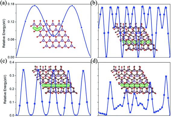 | ||
| Fig. 6 The Li atom diffusion paths and energy barriers. (a) On pristine MoO2. (b) and (c) On the outside of the MoO2 and graphene layers of the nanocomposite. (d) In the interlayer of MoO2/G. | ||
4. Conclusions
Through first-principles calculations, we systematically studied the electronic and Li-diffusion properties of an asymmetric MoO2/G nanocomposite. Our results show that the asymmetric MoO2/G nanocomposite has good stability and that Li atoms can be stably adsorbed in the interlayer and on the outsides of the nanocomposite without the occurrence of clustering. Importantly, because of the charge transfer between MoO2 and graphene, the asymmetric MoO2/G nanocomposite is metallic and has a small diffusion barrier which increases the conductivity of the MoO2/G nanocomposite. Moreover, the van der Waals interactions between MoO2 and graphene will promote adsorption on the two outside layers and on the interlayer of the MoO2/G nanocomposite. The interlayer adsorption of Li atoms can further promote the adsorption of Li atoms on the outside sites of the MoO2 layer, thus increasing the storage capacity. The theoretical specific capacity of the MoO2/G nanocomposite is larger than 1682 mA h g−1, which is much higher than that of graphene and MoO2. These results make MoO2/G an attractive LIBS anode material.Conflicts of interest
There are no conflicts to declare.Acknowledgements
This work is supported by the Fundamental Research Funds for the Central Universities (2652017333) and National Natural Science Foundation of China (Grant No. 11404294 and 51772279).References
- B. Wang, J. S. Chen, H. B. Wu, Z. Wang and X. W. Lou, J. Am. Chem. Soc., 2011, 133, 17146–17148 CrossRef CAS.
- Z. Wang, Z. Wang, W. Liu, W. Xiao and X. W. Lou, Energy Environ. Sci., 2013, 6, 87–91 RSC.
- Y. Gu, F. Wu and Y. Wang, Adv. Funct. Mater., 2013, 23, 893–899 CrossRef CAS.
- Q. Tang, Z. Shan, L. Wang and X. Qin, Electrochim. Acta, 2012, 79, 148–153 CrossRef CAS.
- K. Persson, V. A. Sethuraman, L. J. Hardwick, Y. Hinuma, Y. S. Meng, A. van der Ven, V. Srinivasan, R. Kostecki and G. Ceder, J. Phys. Chem. Lett., 2010, 1, 1176–1180 CrossRef CAS.
- C. Uthaisar and V. Barone, Nano Lett., 2010, 10, 2838–2842 CrossRef CAS.
- L. Zhou, H. B. Wu, Z. Wang and X. W. Lou, ACS Appl. Mater. Interfaces, 2011, 3, 4853–4857 CrossRef CAS.
- Y. Sun, Am. Chem. Soc., 2011, 5(9), 7100–7107 CAS.
- L. Yang, L. Liu, Y. Zhu, X. Wang and Y. Wu, J. Mater. Chem., 2012, 22, 13148 RSC.
- J. Nicks, J. Zhang and J. A. Foster, Chem. Commun., 2019, 55, 8788–8791 RSC.
- Y. Liang, S. Yang, Z. Yi, X. Lei, J. Sun and Y. Zhou, J. Mater. Sci. Eng. B, 2005, 121, 152–155 CrossRef.
- A. Bhaskar, M. Deepa, T. N. Rao and U. V. Varadaraju, J. Power Sources, 2012, 216, 169–178 CrossRef CAS.
- J. Ma, J. Fu, M. Niu and R. Quhe, Carbon, 2019, 147, 357–363 CrossRef CAS.
- G. Kresse, Phys. Rev. B: Condens. Matter Mater. Phys., 1996, 54(16), 11169–11185 CrossRef CAS.
- J. P. Perdew, K. Burke and M. Ernzerhof, Phys. Rev. Lett., 1996, 77, 3865–3868 CrossRef CAS.
- G. Henkelman, B. P. Uberuaga and H. Jónsson, J. Chem. Phys., 2000, 113, 9901–9904 CrossRef CAS.
- X. Lian, M. Niu, Y. Huang and D. Cheng, J. Phys. Chem. Solids, 2018, 120 Search PubMed.
- F. A. Rasmussen and K. S. Thygesen, J. Phys. Chem. C, 2015, 119, 13169–13183 CrossRef CAS.
- C. Ataca, H. Şahin and S. Ciraci, J. Phys. Chem. C, 2012, 116, 8983–8999 CrossRef CAS.
- S. Gong and Q. Wang, J. Phys. Chem. C, 2017, 121, 24418–24424 CrossRef CAS.
- H. J. Hwang, J. Koo, M. Park, N. Park, Y. Kwon and H. Lee, J. Phys. Chem. C, 2013, 117, 6919–6923 CrossRef CAS.
- D. Das, S. Kim, K. R. Lee and A. K. Singh, Phys. Chem. Chem. Phys., 2013, 15, 15128–15134 RSC.
- Q. Peng, K. Hu, B. Sa, J. Zhou, B. Wu, X. Hou and Z. Sun, Nano Res., 2017, 10, 3136–3150 CrossRef CAS.
Footnote |
| † Electronic supplementary information (ESI) available. See DOI: 10.1039/d0ra07690b |
| This journal is © The Royal Society of Chemistry 2020 |

