 Open Access Article
A functional modified graphene oxide/nanodiamond/nano zinc oxide composite for excellent vulcanization properties of natural rubber
Zhen Yang a,
Yan Huanga and
Yuzhu Xiong
 *ab
*ab
aCollege of Materials and Metallurgy, Guizhou University, Guiyang 550025, China. E-mail: xyzhu789@126.com
bGuizhou Provincial Rubber Composite Material Engineering Laboratory, China
First published on 17th November 2020
Abstract
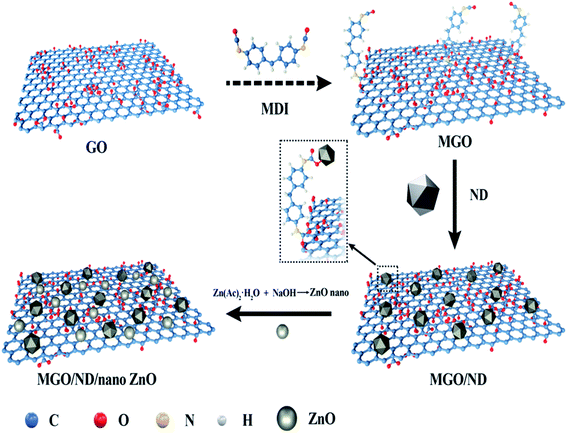
A modified graphene oxide/nanodiamond/nanozinc oxide (MGO/ND/nanoZnO) functional hybrid filler is designed and prepared to improve the vulcanization efficiency of a rubber composite and to reduce the use of ZnO. ND was grafted onto graphite oxide with the aid of 4,4′-methylene diphenyl diisocyanate (MDI). NanoZnO, with high surface activity, was then loaded onto the MGO/ND complex through the wet chemical method, in order to synthesize the MGO/ND/nanoZnO functional hybrid filler. Rubber composites were prepared using the rubber latex composite method and their vulcanization behaviors were investigated. Our results show that the MGO/ND/nanoZnO functional hybrid filler can remarkably improve the vulcanization behaviors of the rubber composite. Compared with that of pure natural rubber (NR), the vulcanization activation energy of the rubber composite was reduced by approximately 16%. Moreover, the vulcanization efficiency can be improved by 63% (i.e., the optimum cure time is shortened from the original 405 s to 150 s) after the same amount of traditional ZnO was replaced by the functional hybrid filler loaded with 1 wt% nanoZnO. The prepared MGO/ND/nanoZnO functional hybrid filler thus provides a promising alternative to improve the vulcanization efficiency of rubber composites.
1. Introduction
In-depth studies on rubber vulcanization behaviors and vulcanization kinetics have been conducted since the discovery of rubber vulcanization technology.1–3 Coran pointed out that scorching is an important part of rubber vulcanization behavior. In this process,4 various accelerants react with sulfur to form crosslinking precursors, which then react with active sites on the rubber chain during vulcanization to form S bonds between macromolecular chains. In order to better describe the vulcanizing and processing properties of NR, Ehabé et al. used Mooney torque relaxation method to characterize natural rubber and synthetic natural rubber, and found that the Maxwell and Wu–Abott models are most suitable for describing rubber vulcanization and processing performance.5 Among them, according to the classification of the curing system, it is divided into three types: conventional (CV), semi-efficient (SEV), and efficient (EV) curing systems, the classification standard is the ratio of sulfur to accelerator. Generally, conventional curing systems have better mechanical properties.6 In addition, ZnO also plays an important role in the vulcanization process. In the description of Mostoni et al., ZnO participates as an activator in the vulcanization process of rubber, the activation process consists of three steps. First, forming a zinc complex with stearic acid and then forming an active accelerator complex with an accelerator and sulfur, and finally reacts with the polymer to form multiple sulfide crosslinked products. With the process of curing reaction, the polysulfide bonds will gradually break to form stable, short sulfur cross-links and finally form a stable 3D network structure.7 Therefore, rubber vulcanization directly affects the quality of the 3D net structure, which supports various properties of the rubber material. In addition, the vulcanization behaviors of the rubber materials also directly influence their applications.ZnO has been widely used in the vulcanization process of NR recently years. Owing to the strict requirements of EU REACH Regulations for the environmental protection property of traditional ZnO, many researchers have focused on reducing the use of traditional ZnO,8 therefore, nanoZnO came into being. NanoZnO is a multifunctional material with extremely high surface activity. It has the characteristics of small particle size and large specific surface area, and has a good effect of promoting vulcanization.9 Kim et al. mixed nanoZnO into natural/butadiene composite rubber materials. They found that, in the silica-filled system, the high specific surface area and good dispersion of nanoZnO significantly promoted the vulcanization behavior and reduced both the scorch time and optimum curing time. Compared with conventional ZnO, 20% nanoZnO content can obtain similar vulcanization characteristics and mechanical properties.10 Thomas et al. and Roy et al. also found that nanoZnO increased the scorch time of rubber and reduced the optimum curing time. They inferred that this may be related to the formation of more crosslinked precursors, due to the high specific surface area of nanoZnO.11,12
Recent works have focused on the use of nanoZnO to partially or completely replace conventional ZnO for rubber vulcanization. Due to the nanometer effect of nanoZnO, it can significantly improve the vulcanization performance of rubber and the utilization rate of rubber vulcanizing agent with a small amount of addition.13 However, nanoZnO has high surface activity; when it is added independently, intense aggregation may occur in the rubber matrix,14 degrading the vulcanization-facilitating effect and adversely influencing the resulting mechanical properties. Therefore, it is particularly important to improve the dispersity of nanoZnO in the rubber matrix. Among the methods to improve the dispersion of nanoZnO, the most commonly used method is to load nanoZnO onto other functional fillers with good dispersion. Numerous studies have shown that loading nanoZnO particles on SiO2 can form a Si–O–Zn covalent bond, and finally makes nanoZnO uniformly dispersed in the rubber matrix along with SiO2, thereby improving the vulcanization efficiency of rubber.15–17 Lin et al. loaded nanoZnO onto the surface of graphene and found that nanoZnO inhibits the aggregation of graphene sheets. The results show that this new hybrid filler had a better vulcanization-facilitating effect.18 In addition, based on the assumption that increased availability of Zn2+ ions may result in a significant reduction of ZnO needed in rubber compounds, Heideman et al. used montmorillonite as a carrier to load Zn2+ ions through an ion exchange process to prepare a new type of vulcanization active agent, ZnClay. Studies have found that ZnClay can not only maintain the vulcanization and physical properties of rubber products of traditional ZnO, but also reduce the impact on the environment. Heideman et al. also found that GaO and MgO are suitable substitutes for ZnO.19,20
To improve the dispersion of nanoZnO in the rubber matrix by loading, it is crucial to select a suitable carrier material. As a derivative of graphene, graphene oxide (GO) contains hybridized carbon atoms with a 2D honeycomb structure; its surface is covered with abundant functional groups that react with numerous compounds. GO is a versatile functional material,21,22 and researchers have noticed the role of GO in rubber vulcanization. Bismark et al. found that reduced GO (rGO) can effectively promote the vulcanization of acrylonitrile-butadiene rubber, because the rGO can be dispersed well in the rubber matrix.23 Wu et al. investigated the effect of graphene addition on the vulcanization kinetics of natural rubber and found that the scorching period was shortened in the presence of graphene and the vulcanization rate was elevated under low graphene filling condition, but restricted under high filling condition; this phenomenon occurs as the basic groups on the graphene surface participate in the vulcanization.24 The strong van der Waals (VDW) forces between GO sheets is essential for the GO-filled polymer material, but the large agglomerates in the polymer matrix hinder the role of GO.25 Therefore, the dispersity of GO-reinforced polymers in the polymer matrix must be improved. Researchers have grafted macromolecular compounds onto GO sheets to inhibit their aggregation and improve their dispersity in the polymer matrix.26,27 Another method to improve dispersity is to prepare hybrid materials. Delville et al. used chemical grafting to prepare a hybrid material composed of molecular/nanoscale organic–inorganic units. This material has the characteristics of chemical and structural diversity, which can effectively improve the performance of polymers.28 Rattanasom et al. used a CB–silica dual phase filler to reinforce natural rubber and found that, when the silica percentage was 20%, the vulcanized rubber had better performance.29 GO has a 2D structure, so other nanoparticles can be imported onto GO sheets to reduce their aggregation. Moreover, the surface of GO contains a large number of active groups, which can provide active sites to form hybrid fillers, it is very suitable as a carrier material.30
Nano-diamond (ND) is a suitable intercalation material for GO because of its unique surface structure, abundant active groups and excellent thermal conductivity and stability.31 At the same time, this material can facilitate rubber vulcanization and epoxy resin curing.32,33 Owing to the active groups on its surface, ND can form hybridized fillers through the modification of grafted macromolecular substances and reactions between groups. However, there are few reports on ND grafted GO. Zhao et al. successfully grafted hydroxylated and aminated ND onto the surface of carbon fiber by covalent bonding. The results showed that the specific surface area of carbon fiber was enlarged by 58%.34 Because the particle size of ND is far smaller than GO sheet diameter, it is feasible to graft ND onto GO surface, and the hybrid of the two materials can greatly promote the vulcanization behavior of rubber.
In this work, we used GO as matrix, grafted ND particles onto GO sheets with coupling agent MDI and expanded the lamellar structure. The functional hybridized filler MGO/ND/nanoZnO was prepared through the in situ loading of nanoZnO onto the MGO/ND complex using the wet chemical method. Then, natural rubber and functional hybrid filler were mixed by rubber latex composite method. Using this method, drying of the obtained nanofiller in a hot oven or freeze dryer could be avoided; this can not only lower the production cost, but also prevent the aggregation of the hybrid materials.35,36 Moreover, the latex compounding method can effectively disperse fillers in polymer matrix and has been widely used.37 Finally, vulcanization behaviors, vulcanization kinetics, and mechanical properties of the resultant rubber composite are investigated, and the related action mechanism is discussed.
2. Experiment
2.1. Materials
Natural rubber (NR) with an average particle size of 1.06 μm and total solid content of 60% was provided by Shenzhen Jitian Chemical Co., Ltd. GO was acquired from Shenzhen Zhongsen Linghang Technology Co., Ltd. ND was obtained from Beijing Guoruisheng Co., Ltd. 4,4′-Methylene diphenyl diisocyanate (MDI), N,N-dimethylformamide (DMF), ethylene glycol, zinc acetate dihydrate (ZnC4H6O4·2H2O), and NaOH (97%) were brought from Shanghai Aladdin Reagent. Other rubber chemicals used were commercially available industrial products.2.2. Preparation of MGO/ND/nanoZnO functional hybridized filler
The preparation process of the functional hybridized material is shown in Fig. 1. A total of 1.8 g GO was dispersed in 50 ml DMF through ultrasonic bath, and the suspension was purged using nitrogen for 20 min. MDI powder was added and the reaction was carried out for 24 h at 60 °C. The mixture was then rinsed using DMF, and any excessive MDI was removed. Finally, MGO was obtained after being treated with the coupling agent. Then, 0.2 g of ND was added in 50 ml of DMF to form a suspension after ultrasonic bath treatment. The ND was then added into the MGO solution and underwent 10 min ultrasonic treatment. The reaction proceeded at 60 °C, with the reaction product continuously stirred for 2 d. The solid products were collected after centrifugation and rinsed using DMF and deionized water at least five times. The MGO/ND complex (i.e., ND adhered to MGO) was finally obtained.The MGO/ND complex (1.8 g, 2.0 g) and ZnC4H6O4·2H2O (1.35 g, 2.70 g, 4.05 g, 5.39 g) were dispersed in 40 ml of ethylene glycol under ultrasonic treatment. Based on the reaction yield (the yield can reach 80% in the case of excessive sodium hydroxide),38 in our experiment, sodium hydroxide was excessive. The mixture was heated to 120 °C while being stirred intensely. Sodium hydroxide, which was dissolved in distilled water, was added into the mixture. After 2 h of stirring, the mixture was cooled to room temperature, centrifuged, and rinsed using absolute ethyl alcohol and deionized water several times. The obtained product was freeze-dried to obtain the MGO/ND/nanoZnO functional hybridized fillers with different loading capacities of nanoZnO at 0.5, 1.0, 1.5, and 2.0 wt%, marked as MGO/ND/0.5 nanoZnO, MGO/ND/1.0 nanoZnO, MGO/ND/1.5 nanoZnO, and MGO/ND/2.0 nanoZnO, respectively. The specific surface area of the nano zinc oxide was measured by the N2 adsorption–desorption method.
2.3. Preparation of NR/MGO/ND/nanoZnO composite material
The composition of the rubber composite material is shown in Table 1. The NR composite material was prepared through latex composite technology, where NR latex and a certain amount of filler suspension were mixed and stirred for 30 min. The latex mixture was then co-solidified immediately, using 0.5% CaCl2 solution, and the solidified solid was dried to constant weight in an air-dry oven at 60 °C. The dried nanocomposite was incorporated with all kinds of rubber chemicals using an open-type, double-roller open mill at room temperature.| Sample code ingredient (phr) | NR | GO | ND | Nano-ZnO | Common-ZnO |
|---|---|---|---|---|---|
| a Phr, parts per hundred of natural rubber by weight. | |||||
| Pure NR | 100 | 0 | 0 | 0 | 5 |
| NR/GO | 100 | 2 | 0 | 0 | 5 |
| NR/MGO/ND | 100 | 1.8 | 0.2 | 0 | 5 |
| NR/MGO/ND/0.5 nanoZnO | 100 | 1.8 | 0.2 | 0.5 | 4.5 |
| NR/MGO/ND/1.0 nanoZnO | 100 | 1.8 | 0.2 | 1 | 4 |
| NR/MGO/ND/1.5 nanoZnO | 100 | 1.8 | 0.2 | 1.5 | 3.5 |
| NR/MGO/ND/2.0 nanoZnO | 100 | 1.8 | 0.2 | 2 | 3 |
Other rubber ingredients (phr): stearic acid (4), accelerator D (0.5), accelerator M (2.21), accelerator DM (1.18), accelerator TMTD (0.32), anti-aging agent 4020 (1.5), sulfur (1.71).
2.4. Characteristic description
The ultrasonic cleaner used was a KQ-100KDB (Kunshan Ultrasonic Instruments Co., Ltd.). Fourier Transform Infrared Spectroscopy (FTIR, Nicolet 6700 Thermo Scientific Co., Ltd., USA) was employed to analyze the change of characteristic groups on the filler surface after hybridization. The chemical compositions of the filler before and after hybridization were analyzed by X-ray photoelectron spectroscopy (XPS, K-Alpha, Thermo Scientific Co. Ltd., USA). X-ray diffraction (XRD, X'Pert-Pro MPD, Panalytical) was performed at 25 °C, Cu target was operated under 40 kV and 30 mA, and XRD data were collected from 4° to 80° at rate of 4° min−1. Thermogravimetric analysis (TGA, TGA5500, TA instrument) was used to investigate the thermal stability under nitrogen atmosphere at heating rate of 10 °C min−1. Ultrasonic treatment of hybridized filler was carried out for 30 min, followed by observation of microstructures under transmission electron microscope (Tecnai G2 F20, FEI Co., Ltd., USA). A temperature-variable magnetic resonance crosslink density spectrometer (VTMR20-010V-I NiuMai, Analytical Instrument Co. China) was used to test the crosslink density of the vulcanized rubber, the measurement was performed at 60 °C, the sample was 10 cm long and 2 cm wide, the instrument's hydrogen test probe coil was 10 mm, the magnet strength was 0.5 T, and the magnet temperature was 35 ± 0.01 °C. Then, 0.5 g of unvulcanized rubber compound sample cut into small pieces were soaked in toluene solution in a clean copper mesh of known quality at room temperature, which was replaced every 24 h for 72 h, and then soaked in acetone solution for 24 h to extract the methylbenzene in the specimen. The undissolved product was then dried to constant weight at 60 °C. The content of bonded rubber in the specimen was then calculated, based on the following formula:
 | (1) |
A swelling test was performed on the vulcanizate in toluene solvent, according to the GB/T 7763-1987 standard. Two complete samples (40–50 mg) were immersed in toluene at 30 °C for 4 hours, and the weights of the samples were measured after swelling. The swelling index of vulcanized rubber was measured according to the following formula; two specimens were measured for every case and the average values were taken:
 | (2) |
A universal testing machine (Hegewald & Peschke Co., Ltd., Germany) was used to measure the tensile strength and tear resistance of the rubber composite material at uniform crosshead velocity of 500 mm min−1, according to the GB/T528-1998 and GB/T529-1999 standards. The sample was obtained at a vulcanization temperature of 150 degrees. The vulcanization characteristic curves of the specimens under different temperatures were tested by MDR (MD-3000, High Speed Rail Technology Co., Ltd., China), according to the GB/T16584-1996 standard. To investigate the vulcanization kinetics of the rubber composites, the vulcanization degree α at a specific time is calculated through the data obtained by the rotor-less vulcameter, which is defined as follows:
 | (3) |
 | (4) |
3. Results and discussion
3.1. Structure and morphology of functional hybridized filler
The FT-IR graph of the filler is shown in Fig. 2(a). Pure GO had a characteristic peak of hydroxyl (–OH) at 3405 cm−1 and a characteristic peak of carbonyl (C![[double bond, length as m-dash]](https://www.rsc.org/images/entities/char_e001.gif) O) at 1730 cm−1. Compared with pure GO, MGO had a new peak at 2870 cm−1, corresponding to the alkyl group (–CH2) of the coupling agent.39 The (–NCO) peak (2230 cm−1) in MGO had disappeared, indicating that the aminoester reaction had occurred. A new (–NH–) stretching vibration peak appeared at 3309 cm−1, which further proved that MDI had been grafted onto GO. In addition, the new (–C
O) at 1730 cm−1. Compared with pure GO, MGO had a new peak at 2870 cm−1, corresponding to the alkyl group (–CH2) of the coupling agent.39 The (–NCO) peak (2230 cm−1) in MGO had disappeared, indicating that the aminoester reaction had occurred. A new (–NH–) stretching vibration peak appeared at 3309 cm−1, which further proved that MDI had been grafted onto GO. In addition, the new (–C![[double bond, length as m-dash]](https://www.rsc.org/images/entities/char_e001.gif) O) stretching vibration peak of MGO appeared at 1644 cm−1, which also proved that MDI was successfully grafted onto GO. According to the IR spectrogram of the MGO/ND/nanoZnO functional hybridized filler, a characteristic peak of ZnO appeared near 500 cm−1.40 Therefore, ZnO was successfully loaded onto the MGO/ND complex.
O) stretching vibration peak of MGO appeared at 1644 cm−1, which also proved that MDI was successfully grafted onto GO. According to the IR spectrogram of the MGO/ND/nanoZnO functional hybridized filler, a characteristic peak of ZnO appeared near 500 cm−1.40 Therefore, ZnO was successfully loaded onto the MGO/ND complex.
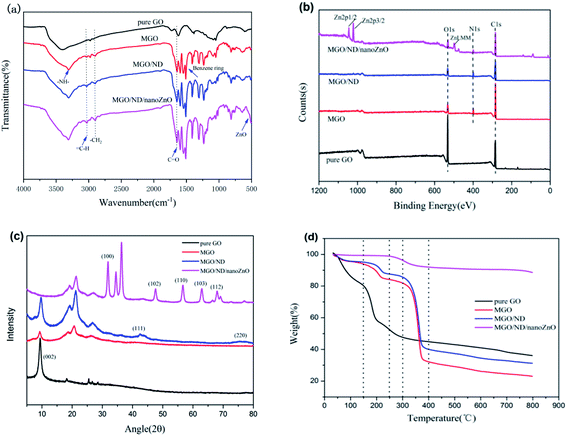 | ||
| Fig. 2 (a) FT-IR spectra, (b) XPS survey spectra, (c) X-ray diffraction pattern spectra, and (d) TGA of GO, MGO, MGO/ND, and MGO/ND/nanoZnO under nitrogen. | ||
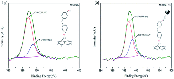
XPS testing was performed to further determine the chemical composition at the surface of the functional hybridized filler; the results are shown in Fig. 2(b). Additionally, the elemental quantitative analysis of hybrid fillers is shown in Table 2. MDI contained nitrogen, the N 1s peak was detected on the XPS graphs of MGO and MGO/ND, and the content of carbon increased and the content of oxygen decreased, corresponding to the reaction of the –NCO functional group, further proving the successful grafting of MDI. Fig. 3(a) and (b) show high-resolution single-scanning graphs of MGO and MGO/ND in N 1s region. Both specimens had two peak values under 398.7 and 399.5 eV, which correspond to –N![[double bond, length as m-dash]](https://www.rsc.org/images/entities/char_e001.gif) CO and N–C
CO and N–C![[double bond, length as m-dash]](https://www.rsc.org/images/entities/char_e001.gif) O groups, respectively. Compared with that in MGO, the –N
O groups, respectively. Compared with that in MGO, the –N![[double bond, length as m-dash]](https://www.rsc.org/images/entities/char_e001.gif) CO peak area in MGO/ND was reduced, to some degree, due to the further reaction of –OH and –N
CO peak area in MGO/ND was reduced, to some degree, due to the further reaction of –OH and –N![[double bond, length as m-dash]](https://www.rsc.org/images/entities/char_e001.gif) CO groups on the ND surface. This finding indicates that the coupling agent MDI successfully linked GO and ND.41 Three characteristic peaks of Zn appeared on the XPS graph of the MGO/ND/nanoZnO functional hybridized filler, and the zinc content accounted for a large proportion of the same quality, further confirming that nanoZnO was successfully loaded onto the surface of MGO/ND complex through the wet chemical method.
CO groups on the ND surface. This finding indicates that the coupling agent MDI successfully linked GO and ND.41 Three characteristic peaks of Zn appeared on the XPS graph of the MGO/ND/nanoZnO functional hybridized filler, and the zinc content accounted for a large proportion of the same quality, further confirming that nanoZnO was successfully loaded onto the surface of MGO/ND complex through the wet chemical method.
| Sample code element (%) | C | O | N | Zn |
|---|---|---|---|---|
| GO | 48.21 | 51.79 | 0 | 0 |
| MGO | 71.95 | 20.97 | 7.08 | 0 |
| MGO/ND | 67.9 | 24.25 | 7.85 | 0 |
| MGO/ND/nanoZnO | 27.82 | 9.69 | 3.15 | 59.34 |
The XRD graph is shown in Fig. 2(c). A new peak appeared in the MGO spectrum at 20°–30°, which corresponds to the structure formed by the grafting of MDI molecules onto GO. (111) and (220) peaks on the MGO/ND graph were characteristic planes of ND,37 proving that ND was successfully grafted from MDI onto the GO. The original characteristic peak and sheet spacing of GO were 2θ = 9.6° and d = 0.92 nm, respectively. After the MDI molecules were grafted onto GO sheets, the characteristic peak and sheet spacing of the MGO complex were 2θ = 9.3° and d = 0.95 nm, respectively. The average particle size of ND was 5–7 nm, which is too large to be inserted between the GO layers. Consequently, the d-spacing (0.95 nm) of the MGO/ND did not change significantly. After nanoZnO was loaded onto the MGO/ND complex, the MGO/ND/nanoZnO functional hybridized filler had numerous XRD peaks characteristic of ZnO;42 however, the characteristic peak of GO disappeared, possibly because nanoZnO exhibited a coating effect and uniformly covered the MGO/ND surface.
Considering the TGA under nitrogen data shown in Fig. 2(d), a mass loss of about 17% below 150 °C was observed, due to the evaporation of adsorbed water molecules. The most significant weight loss (about 40%) was observed between 150–200 °C, due to the pyrolysis of unstable oxygen-containing groups on the GO sheet. From 200 to 800 °C, about 20% of the mass loss was found to be caused by the pyrolysis of the carbon skeleton of GO. MGO and MGO/ND had almost no thermal weight loss below 150 °C, due to the large removal of adsorbed water during the preparation of MGO; the weight loss mainly occurred at about 150–250 °C (about 17%) and 250–400 °C (about 35%). This was due to the pyrolysis of residual oxygen-containing groups and MDI molecules, as well as the degradation of the GO carbon skeleton. The very small weight loss of MGO/ND/nanoZnO between room temperature and 250 °C was due to the evaporation of bound water, while the thermal weight loss between 250–800 °C was due to the pyrolysis of MDI molecules and the carbon skeleton. Nano zinc oxide has good thermal stability as a metal oxide. After densely attaching to the GO plate, the MGO/ND/nanoZnO hybrid functional filler had better thermal stability below 300 °C.
Fig. 4 shows the TEM graph of the functional hybridized filler. Single ND has a particle size of 5–7 nm. The particles showed intense aggregation tendency, being able to aggregate in solution and polymer matrix, and could bear ultrasonic treatment, as shown in Fig. 4(a) and (b).43 Fig. 4(c) and (d) show that the ND particles were well-adhered to the corrugated GO surface. Fig. 4(e) and (f) show the TEM graph regarding nanoZnO loading onto MGO/ND complex and the mapping graph of Zn. Zn uniformly covered the GO surface, certifying that nanoZnO was successfully deposited onto the GO sheets.
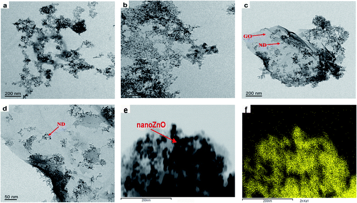 | ||
| Fig. 4 TEM images of (a) the pristine ND nanocluster, (b) magnified ND, and (c) MGO/ND, magnified (d) MGO/ND and (e) MGO/ND/nanoZnO, and (f) zinc element mapping. | ||
3.2. Distribution of functional hybridized filler in natural rubber matrix
Fig. 5 shows the TEM images of vulcanized rubbers with different formulations. Fig. 5(a) and (b) are the TEM images of NR/MGO and NR/MGO/ND vulcanized rubbers, respectively. As shown in the figure, there are smaller zinc oxide particles aggregated in NR/MGO/ND vulcanized rubber. The presence of ND can effectively inhibit the aggregation of GO sheets, thereby improving the distribution of ordinary zinc oxide in the matrix. Fig. 5(c) and (d) are TEM images of NR/MGO/ND/1.0 nanoZnO and NR/MGO/ND/2.0 nanoZnO composite rubbers, respectively. It can be seen from the figure that after loading nano zinc oxide on MGO/ND, not only the use of ordinary zinc oxide is reduced, but also the distribution of nano zinc oxide is promoted, so that the particle size of zinc oxide in rubber composite is significantly smaller, and the distribution of the filler is more uniform. With the increase of nano zinc oxide loading to 2.0 phr, the particle size of zinc oxide aggregates increased slightly. Obviously, excessive nano zinc oxide will increase the tendency of agglomeration. Therefore, the loading amount of nanoZnO should not be too large.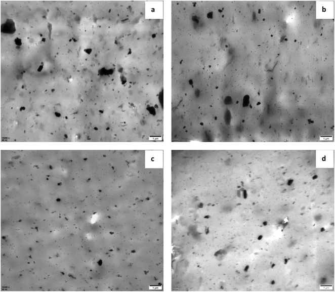 | ||
| Fig. 5 TEM images of vulcanized rubber with different formulations, (a) NR/MGO, (b) NR/MGO/ND, (c) NR/MGO/ND/1.0 nanoZnO, (d) NR/MGO/ND/2.0 nanoZnO. | ||
3.3. Vulcanization behaviors of rubber composite material
Fig. 6 shows the vulcanization curves of different rubber composite materials under four different temperatures. The rubber vulcanization process is well-known to be divided into the following three phases: scorching period, crosslinking period, and reversion period. The scorching period involves the crosslinking precursor formation process of sulfur and various rubber chemicals under a certain temperature. During this period, effective crosslinking is not formed; thus, the torque will not change, which signifies a safe processing period. The crosslinking period involves the reaction process between the crosslinking precursor formed in the previous period and active sites on the rubber chain, wherein the torque (as measured by a rheometer) increases to a maximum value during this period. The reversion period refers to the fracturing process of multi-sulfur bonds (R–Sx–R) formed in the crosslinking period, which results in poor physical properties of the resultant vulcanized rubber. Fig. 6(d) shows that, under high temperatures, the curing curve presents an obvious reversion phenomenon during vulcanization, where addition of the filler does not influence this phenomenon. It has been shown that the cause for this reversion phenomenon is the facilitating effect of high temperatures on the desulfurization reaction; namely, multi-sulfur bonds are easily formed in the crosslinking period fractures under high temperatures.44,45
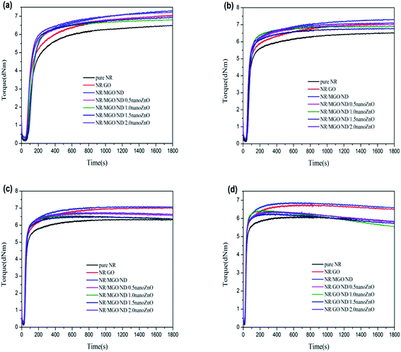 | ||
| Fig. 6 MDR curves of rubber composites at different vulcanization temperatures: (a) 130 °C, (b) 140 °C, (c) 150 °C, and (d) 160 °C. | ||
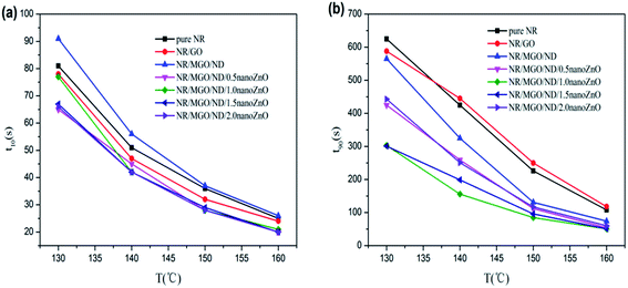
Fig. 7 shows the effects of temperature and different functional hybridized fillers on the scorch time (t10) and optimum curing time (t90) of the rubber composite material. The results show that both the scorch time and optimum curing time of the rubber composite material have an evident temperature dependence. The scorch time of both specimens tended to be identical under high temperatures, as well as their optimum curing time. As previously reported, scorch time is generally dominated by the accelerating activity of the accelerant under vulcanization temperature and mobility of the rubber chain.46 MGO/ND, which had good dispersity in the rubber matrix, effectively inhibited the flow of rubber chains and, thus, more heat had to accumulate to make the chain move. Thus, the NR/MGO/ND composite material had the longest scorch time. The shortening of scorch time after nanoZnO loading was associated with the higher accelerating activity of nanoZnO. The influence of temperature on optimum curing time was more remarkable than that on scorch time, where the long optimum curing time of the NR/GO composite material might be related to adsorption of accelerants onto the GO by active groups.47 Interestingly, the MGO/ND complex reduced the optimum curing time of vulcanized rubber. Based on analysis, this reduction was correlated with the high bound rubber content in the NR/MGO/ND composite material. In general, no rubber chemicals existed in the bound rubber, and high content of bound rubber means increased content of accelerant in the matrix, which serves to promote vulcanization. Another possible reason was that the MGO/ND complex enlarged the heat conductivity of rubber under vulcanization temperature, accelerated heat transfer, and then elevated the vulcanization rate.19
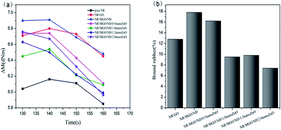
Fig. 8(a) displays the effect of various fillers on effective torque of vulcanized rubber. The effective torque declined under high temperature (160 °C), which was accompanied by a notable reversion phenomenon. The NR/MGO/ND composite material led to the maximum effective torque for the whole process. After in situ nanoZnO loading, the effective torque decreased.
Effective torque is measured as a value of crosslink density in the vulcanized rubber; in addition, crosslink density is an important parameter of vulcanized rubber, which mainly depends on the contents of sulfur and accelerant in the matrix, as well as the ratio of accelerant content to sulfur content.48–50 Moreover, crosslink density has a great impact on the modulus and mechanical properties of vulcanized rubber.51 In general, effective crosslink density in the rubber nanocomposite material involves the chemical crosslinking action of sulfur bonds between rubber chains and the possible physical entanglement (i.e., physical crosslinking) between rubber chains; this interaction does not cause decreased effectiveness in the deformation process.52 The crosslink density and swelling degree of each rubber composite material, as measured by a low-field nuclear magnetic crosslink density meter and the swelling experiment, are shown in Table 3. Based on formula (1), the bound rubber content of each mixed rubber was measured, as shown in Fig. 8(b) below.
| 1 | 2 | 3 | 4 | 5 | 6 | 7 | |
|---|---|---|---|---|---|---|---|
| Crosslink density (10−4 mol cm−3) | 2.11 | 2.38 | 2.54 | 2.44 | 2.17 | 2.13 | 2.12 |
| SI (%) | 4.33 | 4.19 | 3.72 | 4.06 | 4.24 | 4.21 | 4.29 |
Table 3 shows that the addition of filler increased the crosslink density of natural rubber, and that the swelling index also changed with crosslink density. Swelling of the vulcanizate is caused by the penetration of solvent molecules into the gaps between the rubber molecules. The greater the crosslink density of the rubber, the more crosslink points between molecular chains per unit length, which limits the expansion of the rubber chain caused by extensibility, making it difficult for the solvent to penetrate into the gap between the rubber chains, thereby reducing the expansion index.53 The vulcanized rubber with MGO/ND added had the maximum crosslink density, which increased by about 20% in comparison with that of pure natural rubber; at the same time, its swelling index was the smallest, which maintained a corresponding relationship with the crosslink density. The data of bound rubber in Fig. 8(b) show that the specimen with MGO/ND complex added had the maximum content of bound rubber, which indicates that the interaction between MGO/ND and the NR matrix is the strongest, as the ND particles inhibited the aggregation of GO sheets in the natural rubber matrix, making MGO/ND more dispersible in the NR matrix. However, after nanoZnO was loaded onto the MGO/ND complex, the content of bound rubber declined. The reason for this was that nanoZnO coated the MGO/ND complex and weakened the interfacial interaction between the rubber matrix and filler, thus decreasing the content of formed bound rubber.
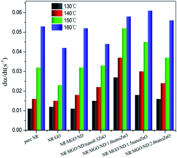
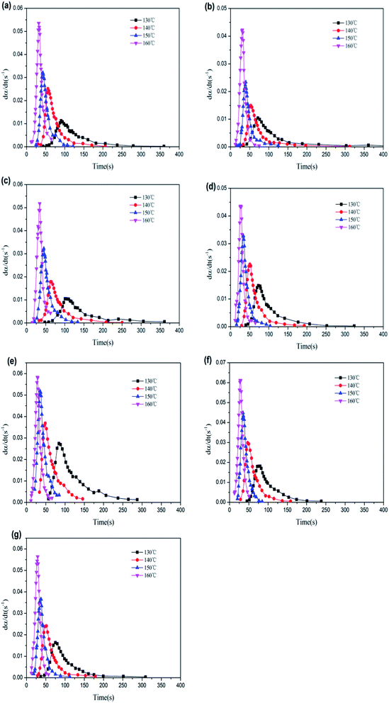
Fig. 10 gives the corresponding relationship between the vulcanization rate of rubber composites and time under different vulcanization temperatures. Vulcanization rates of all specimens were shown to firstly increase and then decrease with vulcanization time, accompanied by notable autocatalytic behavior, which could be explained by the competition between the vulcanization reaction dominated by chemical means and the vulcanization reaction dominated by physical means (i.e., viscosity increase). As predicted by the autocatalysis equation, the maximum reaction rate appeared at any time (except for the start of the reaction) as, during this chemical reaction process, the rubber vulcanization degree was not only related to both the unreacted sulfur and accelerant, but also to the multi-sulfur bonds formed by crosslinking.56
Many dynamical models describing the autocatalysis process have been used in related reports.57,58 The common Kamal–Sourour model used to describe the vulcanization kinetics is defined as follows:59
 | (5) |
 | (6) |
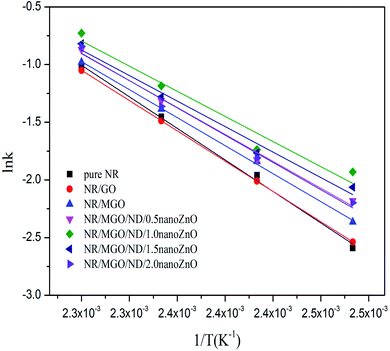
![[thin space (1/6-em)]](https://www.rsc.org/images/entities/char_2009.gif) k, as shown in Fig. 11. The values of k(T), m, n, and E, for all specimens, were fitted and calculated by non-linear regression. The results are listed in Table 4.
k, as shown in Fig. 11. The values of k(T), m, n, and E, for all specimens, were fitted and calculated by non-linear regression. The results are listed in Table 4.
| Sample code | Temp. (°C) | K | Reaction order | E (kJ mol−1) | R2 | |
|---|---|---|---|---|---|---|
| m | n | |||||
| Pure NR | 130 | 0.075 | 0.84 | 3.74 | 75.78 | 0.99 |
| 140 | 0.141 | 0.80 | 2.56 | |||
| 150 | 0.234 | 0.93 | 2.39 | |||
| 160 | 0.357 | 1.03 | 1.97 | |||
| NR/GO | 130 | 0.080 | 0.84 | 3.16 | 77.42 | 0.99 |
| 140 | 0.134 | 0.13 | 3.94 | |||
| 150 | 0.226 | 1.07 | 2.81 | |||
| 160 | 0.350 | 1.11 | 2.17 | |||
| NR/MGO/ND | 130 | 0.094 | 1.02 | 2.77 | 67.01 | 0.99 |
| 140 | 0.159 | 1.02 | 2.76 | |||
| 150 | 0.250 | 1.00 | 2.41 | |||
| 160 | 0.376 | 1.09 | 2.05 | |||
| NR/MGO/ND/0.5 nanoZnO | 130 | 0.113 | 0.86 | 2.97 | 64.44 | 0.98 |
| 140 | 0.161 | 0.87 | 2.67 | |||
| 150 | 0.269 | 1.08 | 2.31 | |||
| 160 | 0.419 | 1.33 | 2.01 | |||
| NR/MGO/ND/1.0 nanoZnO | 130 | 0.145 | 0.72 | 2.52 | 60.22 | 0.96 |
| 140 | 0.177 | 0.71 | 2.18 | |||
| 150 | 0.306 | 0.90 | 2.02 | |||
| 160 | 0.483 | 1.01 | 2.75 | |||
| NR/MGO/ND/1.5 nanoZnO | 130 | 0.127 | 0.85 | 2.70 | 61.14 | 0.97 |
| 140 | 0.171 | 0.18 | 2.31 | |||
| 150 | 0.278 | 0.92 | 2.04 | |||
| 160 | 0.441 | 1.18 | 1.76 | |||
| NR/MGO/ND/2.0 nanoZnO | 130 | 0.111 | 0.85 | 2.62 | 65.44 | 0.98 |
| 140 | 0.164 | 0.86 | 2.48 | |||
| 150 | 0.256 | 0.98 | 2.15 | |||
| 160 | 0.431 | 1.19 | 1.85 | |||
Table 4 shows that the addition of the functional hybridized filler reduced the activation energy of the rubber composite in the optimum curing period. Correspondingly, the vulcanization rate constant was enlarged, due to the high surface activity of nanoZnO; its facilitating effect on rubber vulcanization was remarkably superior to that of traditional ZnO. The vulcanization rate declined when the in situ loading capacity of nanoZnO was greater than 1 wt%. Thus, the optimal loading capacity of nanoZnO must be applied to realize the vulcanization-facilitating effect of the functional hybridized filler; this ability might be related to the aggregation of nanoZnO particles. In summary, the kinetic mechanism of rubber vulcanization is complicated and related to other causes (e.g., chemical catalytic action of the filler).
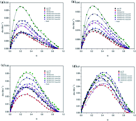
Fig. 12 shows the dα/dt–α relation curves of rubber composite materials under four temperatures. The reaction rate of the rubber composite material increased with the conversion rate at the beginning of the crosslinking period and reached a maximum value within 0.2 to 0.4, which was consistent with the autocatalysis model mentioned previously. Therefore, the experimental data were in good agreement with the model that we selected.
3.4. Mechanical properties of vulcanized rubber
The mechanical properties of vulcanized rubber are listed in Table 5. In general, the interaction between matrix and filler,60 and whether a network is formed between the matrix and the filler are important determinants of the mechanical properties of composite materials. As ND inhibits the aggregation of GO sheets, the dispersibility is improved, the elongation at break of NR/MGO/ND specimen declined, and the tensile strength increased, indicating that the composite rigidity was improved, to a certain degree. The tensile strength, tear strength, elongation at break, 100% stretching strength, and 300% stretching strength of the NR/MGO/ND/1.0 nanoZnO specimen, with the best vulcanization performance, were increased by 59%, 25%, 18%, 9%, and 14%, respectively.| Sample code | Tensile strength (MPa) | Tear strength (MPa) | Elongation break (%) | Stress at 100% strain (MPa) | Stress at 300% strain (MPa) |
|---|---|---|---|---|---|
| Pure NR | 11.39 | 25.23 | 458.86 | 0.99 | 2.71 |
| NR/GO | 11.95 | 25.58 | 516.70 | 1.06 | 2.82 |
| NR/MGO/ND | 6.34 | 26.99 | 365.09 | 1.38 | 4.23 |
| NR/MGO/ND/0.5 nanoZnO | 15.57 | 31.73 | 523.65 | 1.02 | 3.03 |
| NR/MGO/ND/1.0 nanoZnO | 18.16 | 31.47 | 543.19 | 1.08 | 3.11 |
| NR/MGO/ND/1.5 nanoZnO | 21.34 | 33.34 | 534.36 | 1.09 | 3.31 |
| NR/MGO/ND/2.0 nanoZnO | 23.15 | 33.22 | 529.57 | 1.16 | 3.54 |
4. Conclusions
ND and nanoZnO particles were added onto the surface of GO through chemical grafting and physical deposition, respectively, to prepare a MGO/ND/nanoZnO functional hybridized material for use in the latex composite method with GO as the carrier and 4,4′-methylene diphenyl diisocyanate (MDI) as the coupling agent. A vulcanization kinetics study indicated that the vulcanization of natural rubber conformed to the autocatalysis model, where pure GO had only a minor influence on the vulcanization behaviors of natural rubber. Meanwhile, the MGO/ND complex shortened the optimum curing time of natural rubber. When 1 wt% nanoZnO was loaded onto the MGO/ND complex, the activation energy of the rubber composite decreased by 16% in the crosslinking period and the vulcanization efficiency was improved by approximately 63%. This phenomenon was associated with the favorable dispersity of the hybridized filler in the rubber matrix and its high surface activity. Furthermore, the tensile strength, tear strength, elongation at break, 100% stretching strength, and 300% stretching strength of the NR/MGO/ND/1.0 nanoZnO specimen were elevated by 59%, 25%, 18%, 9%, and 14%, respectively, compared with those of pure NR. These results indicate that the prepared MGO/ND/nanoZnO functional hybridized filler can remarkably promote the vulcanization characteristics of natural rubber.Conflicts of interest
There are no conflicts of interest to declare.Acknowledgements
We gratefully acknowledge financial support from the National Natural Science Foundation of China (NSFC No. 51663003), Science and Technology Foundation of Guizhou Province (Grant No. [2019]2166).Notes and references
- J. E. Mark, B. Erman and M. Roland, The science and technology of rubber, Academic press, 2013 Search PubMed.
- R. Ding and A. I. Leonov, J. Appl. Polym. Sci., 1996, 61, 455–463 CrossRef CAS.
- L. M. Lopez, A. B. Cosgrove, J. P. Hernandez-Ortiz and T. A. Osswald, Polym. Eng. Sci., 2007, 47, 675–683 CAS.
- A. Y. Coran, Rubber Chem. Technol., 1965, 38, 1–14 CAS.
- E. Ehabé, F. Bonfils, C. Aymard, A. K. Akinlabi and J. Sainte Beuve, Polym. Test., 2005, 24, 620–627 CrossRef.
- N. Rattanasom, A. Poonsuk and T. Makmoon, Polym. Test., 2005, 24, 728–732 CrossRef CAS.
- S. Mostoni, P. Milana, B. D. Credico, M. D'Arienzo and R. Scotti, Catalysts, 2019, 9, 664 CrossRef.
- A. Ansarifar, L. Wang, R. J. Ellis and Y. Haile-Meskel, J. Appl. Polym. Sci., 2011, 119, 922–928 CrossRef CAS.
- B. Panampilly and S. Thomas, Polym. Eng. Sci., 2013, 53, 1337–1346 CrossRef CAS.
- I. J. Kim, W. S. Kim, D. H. Lee, W. Kim and J. W. Bae, J. Appl. Polym. Sci., 2010, 117, 1535–1543 CAS.
- S. P. Thomas, E. J. Mathew and C. V. Marykutty, J. Appl. Polym. Sci., 2012, 124, 3099–3107 CrossRef CAS.
- K. Roy, M. N. Alam, S. K. Mandal and S. C. Debnath, J. Sol-Gel Sci. Technol., 2014, 70, 378–384 CrossRef CAS.
- A. Moezzi, A. M. Mcdonagh and M. B. Cortie, Chem. Eng. J., 2012, 185, 1–22 CrossRef.
- E. Tang, G. Cheng, X. Ma, X. Pang and Q. Zhao, Appl. Surf. Sci., 2006, 252, 5227–5232 CrossRef CAS.
- M. Gaca, J. Pietrasik, M. Zaborski, L. Okrasa, G. Boiteux and O. Gain, Polymers, 2017, 9, 645 Search PubMed.
- A. Susanna, L. Armelao, E. Callone, S. Dirè, M. D'Arienzo, B. D. Credico, L. Giannini, T. Hanel, F. Morazzoni and R. Scotti, Chem. Eng. J., 2015, 275, 245–252 CAS.
- A. Susanna, M. D'Arienzo, B. D. Credico, L. Giannini, T. Hanel, R. Grandori, F. Morazzoni, S. Mostoni, C. Santambrogio and R. Scotti, Eur. Polym. J., 2017, 93, 63–74 CrossRef CAS.
- Y. Lin, Y. Chen, Z. Zeng, J. Zhu, Y. Wei, F. Li and L. Liu, Composites, Part A, 2015, 70, 35–44 CrossRef CAS.
- G. Heideman, J. W. M. Noordermeer, R. N. Datta and B. V. Baarle, Kautsch. Gummi Kunstst., 2003, 12, 650–656 Search PubMed.
- G. Heideman, J. Noordermeer, R. N. Datta and B. V. Baarle, Macromol. Symp., 2006, 245, 657–667 CrossRef.
- L. T. Tam, N. X. Dinh, N. V. Cuong, M. V. Quy, T. Q. Huy, D. Ngo, K. MØlhave and A. Le, J. Electron. Mater., 2016, 45, 5321–5333 CrossRef CAS.
- T. H. Fatt, Development of Graphene Oxide Based Functional Materials, 2014 Search PubMed.
- B. Mensah, K. C. Gupta, G. Kang, H. Lee and C. Nah, Polym. Test., 2019, 76, 127–137 CrossRef CAS.
- J. Wu, W. Xing, G. Huang, H. Li, M. Tang, S. Wu and Y. Liu, Polymer, 2013, 54, 3314–3323 CrossRef CAS.
- R. Scaffaro and A. Maio, Chem. Eng. J., 2016, 308, 1034–1047 CrossRef.
- B. Yin, J. Wang, H. Jia, J. He, X. Zhang and Z. Xu, J. Mater. Sci., 2016, 51, 5724–5737 CrossRef CAS.
- Y. T. Park, Y. Qian, C. Chan, T. Suh, M. G. Nejhad, C. W. Macosko and A. Stein, Adv. Funct. Mater., 2015, 25, 575–585 CrossRef CAS.
- M. H. Delville and A. Taubert, Hybrid Organic-Inorganic Interfaces: Towards Advanced Functional Materials, John Wiley & Sons, 2018 Search PubMed.
- N. Rattanasom, T. Saowapark and C. Deeprasertkul, Polym. Test., 2007, 26, 369–377 CrossRef CAS.
- M. Acik, G. Lee, C. Mattevi, A. Pirkle, R. M. Wallace, M. Chhowalla, K. Cho and Y. Chabal, J. Phys. Chem. C, 2011, 115, 19761–19781 CrossRef CAS.
- L. Zhang, K. Zhou, Q. Wei, L. Ma, W. Ye, H. Li, B. Zhou, Z. Yu, C. T. Lin, J. Luo and X. Gan, Appl. Energy, 2019, 233, 208–219 CrossRef.
- S. Rabiei and A. Shojaei, Eur. Polym. J., 2016, 81, 98–113 CrossRef CAS.
- X. Luo, X. Yu, Y. Ma, K. Naito and Q. Zhang, Thermochim. Acta, 2018, 663, 1–8 CrossRef CAS.
- F. Zhao, R. Liu, X. Yu, H. Ding, X. Qu and Q. Zhang, J. Nanosci. Nanotechnol., 2015, 15, 5807–5815 CrossRef CAS.
- D. Ponnamma, S. H. Sung, J. S. Hong, K. H. Ahn, K. T. Varughese and S. Thomas, Eur. Polym. J., 2014, 53, 147–159 CrossRef CAS.
- M. M. Senna, R. M. Mohamed, A. N. Shehab-Eldin and S. Ei-Hamouly, J. Ind. Eng. Chem., 2012, 18, 1654–1661 CrossRef CAS.
- S. Varghese and J. Karger-Kocsis, Polymer, 2003, 44, 4921–4927 CrossRef CAS.
- D. M. Khan, A. Kausar and S. M. Salman, J. Macromol. Sci., Polym. Rev., 2015, 55, 744–768 Search PubMed.
- Y. Zhang, K. Y. Rhee and S. J. Park, Composites, Part B, 2017, 114, 111–120 CrossRef CAS.
- T. L. Thanh, Q. L. A. Bao and H. N. Huu, Int. J. Nanotechnol., 2018, 15, 108–117 CrossRef.
- Y. Zhang and S. J. Park, Composites, Part A, 2018, 112, 356–364 CrossRef CAS.
- D. Fu, G. Han, Y. Chang and J. Dong, Mater. Chem. Phys., 2012, 132, 673–681 CrossRef CAS.
- R. Martín, P. C. Heydorn, M. Alvaro and H. Garcla, Chem. Mater., 2009, 21, 4505–4514 CrossRef.
- A. Khouider, J. Bouzon and J. M. Vergnaud, Thermochim. Acta, 1986, 98, 285–299 CrossRef CAS.
- G. Milani, E. Leroy, F. Milani and R. Deterre, Polym. Test., 2013, 32, 1052–1063 CrossRef CAS.
- N. Z. Noriman, H. Ismail and A. A. Rashid, Polym. Test., 2010, 29, 200–208 CrossRef CAS.
- A. D. Falco, A. J. Marzocca, M. A. Corcuera, A. Eceiza, I. Mondragon, G. H. Rubiolo and S. Goyanes, J. Appl. Polym. Sci., 2009, 113, 2851–2857 CrossRef.
- A. J. Marzocca, A. L. R. Garraza, P. Sorichetti and H. O. Mosca, Polym. Test., 2010, 29, 477–482 CrossRef CAS.
- A. J. Marzocca and M. A. Mansilla, J. Appl. Polym. Sci., 2007, 103, 1105–1112 CrossRef CAS.
- R. Hagen, L. Salmén and B. Stenberg, J. Polym. Sci., Part B: Polym. Phys., 1996, 34, 1997–2006 CrossRef CAS.
- Y. Lei, Z. Tang, L. Zhu, B. Guo and D. Jia, Polymer, 2011, 52, 1337–1344 CrossRef CAS.
- M. A. López-Manchado, J. L. Valentín, J. Carretero, F. Barroso and M. Arroyo, Eur. Polym. J., 2007, 43, 4143–4150 CrossRef.
- M. A. Kader and A. K. Bhowmick, Polym. Degrad. Stab., 2003, 79, 283–295 CrossRef CAS.
- Y. H. Chen, L. Deng, Z. B. Man and M. Yang, Adv. Mater. Res., 2011, 236–238, 1757–1760 CAS.
- S. Akhlaghi, M. Kalaee, S. Mazinani, E. Jowdar, A. Nouri, A. Sharif and N. Sedaghat, Thermochim. Acta, 2012, 527, 91–98 CrossRef CAS.
- G. Sui, W. H. Zhong, X. P. Yang and Y. H. Yu, Mater. Sci. Eng., A, 2008, 485, 524–531 CrossRef.
- H. S. Y. Hsich, J. Appl. Polym. Sci., 1982, 27, 3265–3277 CrossRef CAS.
- K. Jönsson and P. Flodin, J. Appl. Polym. Sci., 1991, 43, 1777–1787 CrossRef.
- M. R. Kamal and S. Sourour, Polym. Eng. Sci., 1973, 13, 59–64 CrossRef CAS.
- S. R. Dhakate and O. P. Bahl, Carbon, 2003, 41, 1193–1203 CrossRef CAS.
| This journal is © The Royal Society of Chemistry 2020 |

