 Open Access Article
Three-dimensional ordered macroporous ZIF-8 nanoparticle-derived nitrogen-doped hierarchical porous carbons for high-performance lithium–sulfur batteries†
Xinxin Ji a,
Qian Lib,
Haoquan Yua,
Xiaolin Hua,
Yuanzheng Luo
 *c and
Buyin Li*a
aHuazhong University of Science and Technology – Main Campus, China. E-mail: libuyin@hust.edu.cn
bWuhan National Laboratory for Optoelectronics, School of Optical and Electronic Information, Huazhong University of Science and Technology, China
cGuangdong Ocean University, China. E-mail: yuanzluo@163.com
First published on 18th November 2020
Abstract
Lithium–sulfur (Li–S) batteries have attracted considerable attention due to their ultra-high specific capacity and energy density. However, there are still problems to be resolved such as poor conductivity of sulfur cathodes and dissolution of polysulfides in organic electrolytes. Herein, a novel ZIF-8-derived nitrogen-doped connected ordered macro–microporous carbon (COM-MPC) was developed by a dual solvent-assisted in situ crystallization method within a face-centered cubic stacking sphere template, which acts as an advanced sulfur host for enhanced Li–S battery performance. Compared with the conventional predominant microporous C-ZIF-8, the unique hierarchical macro–microporous structure with nitrogen doping not only renders polysulfide intermediates enhanced entrapment by confining the effect of micropores and chemisorption of doping N atoms, but also facilitates electrolyte accessibility and efficient ion transport owing to the ordered macroporous structure. Benefitting from this, the COM-MPC@S cathode delivers a high initial specific capacity of 1498.5 mA h g−1 and a reversible specific capacity of 1118.9 mA h g−1. Moreover, the COM-MPC@S cathode exhibits 82.3% of capacity retention within 10th to 50th cycle at 0.5C and a large capacity of 608.5 mA h g−1 after 50 cycles at a higher rate of 1C, and this enhanced cycling stability and rate capability demonstrate great practical application potential in Li–S battery systems.
1 Introduction
Electric vehicles whose core components contain energy storage systems have expanded rapidly in recent years, driving the demand for high capacity batteries to increase sharply.1 Compared with transition metal-based cathodes in currently dominant Li-ion batteries (LIBs), sulfur could combine much more Li+ ions under the consumption of the same amount,2,3 endowing lithium–sulfur (Li–S) batteries with remarkable theoretical specific capacity (1675 mA h g−1) and energy density (2600 W h kg−1),4 which could greatly relieve the range anxiety of users for electric vehicles. Besides, the advantages of low cost, environmental friendliness and abundant reserve make sulfur quite appropriate for commercial applications. However, except for the theoretical capacity, the state-of-the-art Li–S batteries are not a patch on LIBs in almost all respects, making it merely a potential rather than actual successor at present. In terms of cathode, extremely low conductivity of sulfur and lithium sulfide, severe volume variation (∼80%) upon cycling and, most importantly, the reaction intermediate polysulfide dissolving and freely shuttling in the electrolyte, which lead to a series of problems such as self-discharge, anode corrosion and electrolyte depletion, are the main barriers that need to be handled in pursuit of good practical cell performance.To overcome the aforementioned technical obstacles, various efforts have been devoted to optimizing the structure of conductive cathodes by adopting novel materials,5,6 altering the constitution of liquid electrolytes or using solid electrolytes,7–11 and protecting and stabilizing Li-metal anodes.12,13 Most of these studies have focused on designing cathodes such as porous carbons,14,15 graphene/graphene oxide nanosheets,16,17 conductive polymers18,19 and metal oxides/chalcogenides,5,20 which have been explored to improve Li–S battery performance. Particularly, porous carbon materials are considered as most promising candidates, which can not only improve active sulfur utilization via enhancing the electronic conductivity of composite materials and accommodate volume expansion by means of abundant porosity, but also alleviate the “shuttle effect” of polysulfides via physical restriction of their narrow pores.21,22 According to the pore size, porous carbons are classified into three categories: (i) microporous carbons (<2 nm), which have been proved as the excellent container for sulfur homogenization and confining, tend to demonstrate abnormal electrochemical properties when the pore were extremely cramped;23,24 (ii) mesoporous carbons (>2 nm and <50 nm), which can sustain high sulfur loadings on account of the larger pore, enhance sulfur encapsulation as well as lithium ion transport of Li–S batteries;15 (iii) macroporous carbons (>50 nm), owing to their tremendous pore size,25,26 usually act as an auxiliary structure to promote electrolyte immersion. To comprehensively utilize the advantages of the different aforementioned apertures, the construction of a hierarchical porosity structure whose effects have been frequently reported previously for electrochemical energy storage/conversion applications, such as in LIBs,27,28 Li–O2 batteries,29 EDLC,30,31 hydrogen storage devices32,33 and fuel cells34,35 was very important.
Recently, metal–organic framework (MOF) materials, which consist of metal ions bridged by multidentate organic ligands through coordinate bonds, have been widely applied for electrochemical energy storage and conversion domains including sulfur immobilization benefiting from their ample porosity, diverse structures, tunable pore size, massive surface area and stable chemical properties.36 Moreover, most pristine MOFs possess poor electronic conductivity; therefore, using MOFs as sacrificial templates to obtain porous carbons by a simple one-step calcination process also attracts much attention.37 Apart from inheriting properties of abundant porosity, high surface area from the precursor to boost the electron contact with sulfur and redox activity, the MOF-derived porous carbons achieve homogeneous heteroatom doping owing to organic ligands, which could restrain the migration of polysulfides by chemisorption.38 However, the ordered coordination between metal cations and organic ligands results in a relatively narrow pore distribution, mainly microporosity, of most MOFs, which limits the performance of MOFs and derived carbons in lithium–sulfur batteries. In fact, predominant microporosity in the cathode obstruct electrolyte immersion as well as Li+ ion transportation, causing redox kinetics inhibition and poor cycle stability,39 while pure macropores are unable to prevent polysulfides from shuttling. Thus, the rational design of MOF-derived carbons with hierarchical pore structures is essential and important in pursuing for high capacity, enhanced rate capability and long-term cycle stability.
Herein, we report the fabrication of ZIF-8-derived nitrogen-doped connected ordered macro–microporous carbons (denoted as COM-MPCs) by a dual solvent-assisted in situ crystallization method within face-centered cubic (fcc) stacking sphere templates. Based on abundant micropores inherited from ZIF-8, the COM-MPC introduces 3D interconnected ordered macropores that stem from removing the fcc template to obtain a hierarchical porous structure. The COM-MPC@S composite cathode was then prepared by a melt-diffusion process, delivering an initial discharge capacity of 1498.5 mA h g−1 and retaining 828.1 mA h g−1 after 30 cycles at 0.1C. Furthermore, benefiting from better electrolyte accessibility and efficient ion transport of the macroporous structure, the composite material demonstrates better rate capability than some other materials.25,40,41 The COM-MPC@S cathode exhibits a capacity retention of 82.3% within 10th to 50th cycle at 0.5C and still maintains a large capacity of 608.5 mA h g−1 after 50 cycles at a higher rate of 1C, with a coulombic efficiency of over 97%. These excellent electrochemical properties make the hierarchical porous carbon materials with connected ordered macropores and micropores promising candidates in lithium–sulfur battery systems.
2 Experimental section
2.1 Materials and synthesis
Fcc-PS templates were prepared by a quick self-assembly method with the help of centrifugal force. The aforementioned emulsion was ultrasonicated for 30 min to be well dispersed and then centrifuged at 2000 rpm for 36 h. Drying the precipitations at 60 °C overnight, we obtained the 3D ordered polymer sphere templates.
![[thin space (1/6-em)]](https://www.rsc.org/images/entities/char_2009.gif) :
:![[thin space (1/6-em)]](https://www.rsc.org/images/entities/char_2009.gif) 1 ratio, by volume) under −0.6 MPa for 3 min before the mixture stood at normal temperature and pressure for 24 h. At this stage, preZIF-8@Fcc-PS would split into pieces resulting from the crystallization force. Subsequently, the mixed solvent was poured away and the obtained fragments were dried for several hours (ZIF-8@Fcc-PS). At last, ZIF-8@Fcc-PS was immersed into dimethyl formamide (DMF, Sinopharm, AR) for 24 h to remove the polystyrene sphere templates, and this process was repeated 5 times in order to wash completely.
1 ratio, by volume) under −0.6 MPa for 3 min before the mixture stood at normal temperature and pressure for 24 h. At this stage, preZIF-8@Fcc-PS would split into pieces resulting from the crystallization force. Subsequently, the mixed solvent was poured away and the obtained fragments were dried for several hours (ZIF-8@Fcc-PS). At last, ZIF-8@Fcc-PS was immersed into dimethyl formamide (DMF, Sinopharm, AR) for 24 h to remove the polystyrene sphere templates, and this process was repeated 5 times in order to wash completely.![[thin space (1/6-em)]](https://www.rsc.org/images/entities/char_2009.gif) :
:![[thin space (1/6-em)]](https://www.rsc.org/images/entities/char_2009.gif) 3 mass ratio in a quartz mortar via grinding and then the mixture was sealed in a Teflon container filled with argon. After that, the container was thermally treated at 155 °C for 24 h to promote sulfur infiltration thoroughly into the holes of the COM-MPC. As a contrast, C-ZIF-8 was treated using the same procedure (denoted as C-ZIF-8@S).
3 mass ratio in a quartz mortar via grinding and then the mixture was sealed in a Teflon container filled with argon. After that, the container was thermally treated at 155 °C for 24 h to promote sulfur infiltration thoroughly into the holes of the COM-MPC. As a contrast, C-ZIF-8 was treated using the same procedure (denoted as C-ZIF-8@S).2.2 Material characterization
Scanning electron microscopy (SEM, ZEISS – GeminiSEM 300, 2 kV) was used for investigating the microstructure of the samples prepared in this study. X-ray diffraction (XRD, BRUKER – D8 Advance) was applied to analyse the phase of the samples with Cu(Kα) radiation. To ascertain the sulfur loading of COM-MPC@S and C-ZIF-8@S, thermogravimetric analysis (TGA, NETZSCH – sta449c) was conducted in argon by heating up to 550 °C at a rate of 15 °C min−1. The surface chemical state of the COM-MPC was probed by X-ray photoelectron spectroscopy (XPS, Thermo Fisher – ESCALAB 250Xi) with monochromatic Al Kα radiation. Raman spectra analysis was performed using a Thermo Fisher DRX at a laser wavelength of 633 nm. The nitrogen adsorption–desorption analysis was performed using a Micromeritics ASAP 2460 after 14 h degassing at 200 °C, and the values were calculated by the Brunauer–Emmett–Teller (BET), Barrett–Joyner–Halenda (BJH) and Horvath–Kawazoe (HK) methods.2.3 Electrochemical measurements
To prepare the cathode slurry, 70 wt% COM-MPC@S (or C-ZIF-8@S) composite, 20 wt% acetylene carbon black and 10 wt% polyvinylidene fluoride (PVDF) were uniformly blended in a N-methyl pyrrolidone (NMP) solvent under magnetic stirring for 4 h. The slurry was blade-coated on an aluminum foil and then dried successively in a blast and vacuum drying oven at 60 °C overnight. After drying, the composite was tailored into discs of 13 mm diameter and tabletting under 6 MPa to form the working electrode. In order to examine the electrochemical performance of the COM-MPC@S cathode and comparison samples, the working electrode was assembled into a 2032-type coin cell with a lithium foil serving as the counter electrode and Celgard 2400 polypropylene as the separator in a glovebox full of argon. The electrolyte (70 μL per cell) was constituted by 1 M lithium bis-trifluoromethanesulfonimide (LiTFSI) dissolving in a mixed solvent of 1,3-dioxolane and 1,2-dimethoxyethane (DOL and DME, 1![[thin space (1/6-em)]](https://www.rsc.org/images/entities/char_2009.gif) :
:![[thin space (1/6-em)]](https://www.rsc.org/images/entities/char_2009.gif) 1 ratio, by volume), with 1 wt% LiNO3 as the additive. Cyclic voltammetry (CV) and electrochemical impedance spectroscopy (EIS) tests were carried out using a CS310H (CorrTest Co., Ltd, Wuhan) electrochemical workstation. CV tests were performed at a potential window of 1.5–2.8 V versus Li+/Li at a scan rate of 0.1 mV s−1, while the EIS was collected within the frequency range of 100 kHz to 0.01 Hz. Galvanostatic charge/discharge measurement was conducted using a LAND CT 2100A (LANHE Co., Ltd, Wuhan) battery tester.
1 ratio, by volume), with 1 wt% LiNO3 as the additive. Cyclic voltammetry (CV) and electrochemical impedance spectroscopy (EIS) tests were carried out using a CS310H (CorrTest Co., Ltd, Wuhan) electrochemical workstation. CV tests were performed at a potential window of 1.5–2.8 V versus Li+/Li at a scan rate of 0.1 mV s−1, while the EIS was collected within the frequency range of 100 kHz to 0.01 Hz. Galvanostatic charge/discharge measurement was conducted using a LAND CT 2100A (LANHE Co., Ltd, Wuhan) battery tester.
3 Results and discussion
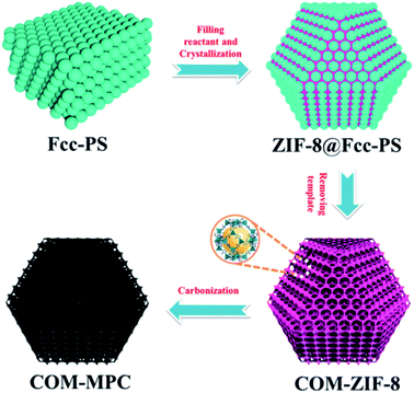
Fig. 1 schematically outlines the preparation process of the COM-MPC. First, the highly ordered fcc stacking polystyrene sphere (PS) templates were obtained by centrifuging the monodisperse PS emulsion at a suitable speed. The interspace of the templates was then crammed with a concentrated methanol solution of zinc nitrate hexahydrate and 2-methylimidazole. Subsequently, under the effect of the methanol/ammonia mixture, the reactants in PS templates were induced to grow into ZIF-8 crystals, yielding ZIF-8@Fcc-PS. Finally, after eliminating PS templates by dissolving in excess dimethylformamide (DMF), the product, i.e., connected ordered macroporous ZIF-8 (COM-ZIF-8), was thermally treated at 800 °C to implement carbonization, and the COM-MPC was acquired. As a contrast, pure microporous N-doping carbon was also synthesized via straightly carbonizing the conventional ZIF-8 (denote as C-ZIF-8).Fig. 2 displays the SEM images of samples after carbonization, which unmasks the difference in morphology between the COM-MPC and C-ZIF-8. The ordered periodic macroporous array inherited from fcc stacking PS templates (Fig. 2a) with a pore size of ∼210 nm was merely observed within the COM-MPC. Moreover, unlike the truncated rhombic dodecahedron shape of C-ZIF-8 (Fig. 2d) consisting of quadrates and hexagons, the microstructure of COM-ZIF-8 is composed of 6 square faces and 8 triangular faces, presenting the appearance of a cuboctahedron, as shown in Fig. 2b and c. In our previous work,44 the effect of PS templates on MOF crystallization has been demonstrated. In brief, as shown in Fig. S1,† every sphere in periodic fcc stacking structure is tightly encircled by 12 other spheres, which divide the space into 14 parts with 6 {100} orientations and 8 {111} orientations. Thus, the reactant in templates can only grow towards these directions and eventually form a cuboctahedron with 14 facets. During the carbonization process, the frame structure of the precursor was well preserved and the unconventional COM-MPC was obtained.
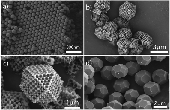 | ||
| Fig. 2 (a) SEM images of fcc stacking PS templates. (b and c) SEM images at different magnifications of the COM-MPC. (d) SEM images of C-ZIF-8. | ||
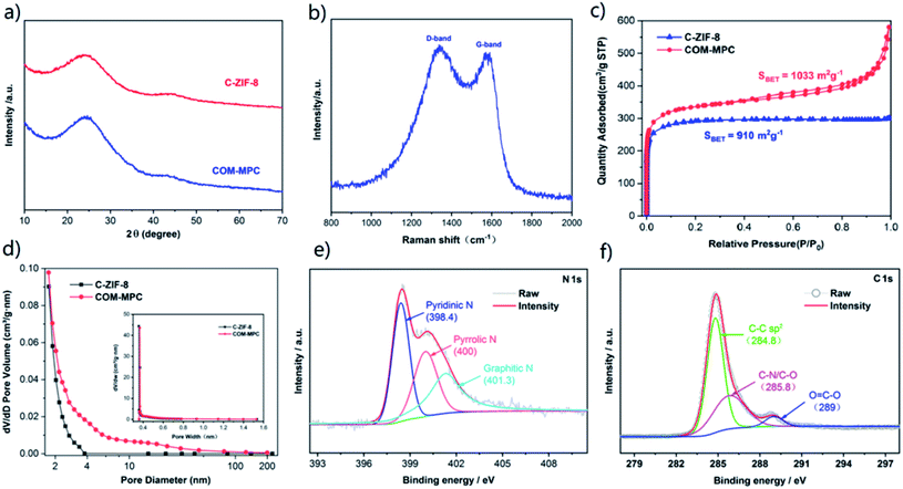
To analyze the crystallography of carbonized samples, the XRD patterns of the COM-MPC and C-ZIF-8 were collected. As shown in Fig. 3a, both of the diffraction spectra were highly consistent. According to Bragg's law, the wide diffraction peaks around 25° and 44° corresponding respectively to the {002} and {101} facets of graphite indicated that the interlayer distances vary to a large extent, confirming the formation of amorphous carbons. In addition, the absence of other impurity phases verified that zinc was completely eliminated during the procedure of pyrolysis and pickling. As a contrast, the samples before carbonization were also analyzed by XRD (Fig. S2†), which displays highly coincident diffraction peaks between these samples and the simulated pattern, demonstrating good crystallinity. For further quantifying the degree of graphitization, Raman spectroscopic investigation was carried out and the result is shown in Fig. 3b. Two distinct peaks centered around 1337 cm−1 and 1571 cm−1 could be assigned to the D-band and G-band of carbons, which were usually derived from the disordered structure of sp3 hybridization defects and the in-plane stretching vibration of graphite flakes, respectively.45 The intensity ratio value of the D-band and G-band (ID/IG) of the COM-MPC was 1.04, representing a relatively low graphitization degree.
N2 adsorption–desorption analysis was employed to study the pore structure of the COM-MPC and the comparison sample. As shown in Fig. 3c, the type-I isotherms of C-ZIF-8 indicate a predominant microporosity with a BET surface of 910 m2 g−1, while the COM-MPC displays a larger BET surface of 1033 m2 g−1 and a curve with combined type-I and type-IV isotherms, which indicate a hybrid structure of micropores (type-I) coupled with mesopores (type-IV). Moreover, the ever-rising adsorption amount at the end of curve of the COM-MPC proves the existence of macroporous structures.26 The detailed pore size distribution of samples is illustrated in Fig. 3d. The COM-MPC possesses a bigger pore volume (0.708 cm3 g−1 vs. 0.459 cm3 g−1) and a more diverse pore size above 2 nm than C-ZIF-8, while the microporous part inherited from ZIF-8 was highly consistent (as shown in inset). Compared with the narrow pore size distribution within C-ZIF-8, such a hierarchical porous structure with enhancement in meso/macroporosity is expected to extra accelerate the electrolyte immersion and Li+ transfer.
XPS analysis was performed to determine the elemental composition and chemical state of the COM-MPC. The comprehensive XPS spectrum displayed in Fig. S3† shows that only C, N and O elements can be detected on the surface of the COM-MPC. Owing to the inexistence of oxygen elements in the COM-ZIF-8 precursor, the oxygen signal is probably assigned to oxygen or water adsorbed within pores being combined into the carbon framework chemically under the action of high temperature during carbonization.46 In addition, we successfully achieved uniform in situ nitrogen doping in the porous carbon with a N content of 8.78% originating from the 2-methylimidazole ligand. According to the N 1s high-resolution spectrum (Fig. 3e), the N element in the COM-MPC mainly exists in three forms, namely pyridinic-N with a binding energy of 398.4 eV, pyrrolic-N with 400 eV and graphitic-N with 401.3 eV, accounting respectively for 38.7%, 29.6%, and 31.7% of the total nitrogen content. Owing to the strong chemical interaction between Li–N, the doped nitrogen, mainly pyridinic-N and pyrrolic-N, is expected to serve as a reacting active site to immobilize polysulfides via this chemical adsorption effect, thereby improving the battery capacity and coulombic efficiency. Moreover, as illustrated in the C 1s high-resolution spectrum (Fig. 3f), three peaks located at 284.8, 285.8 and 289 eV correspond to the sp2 carbon, C–N/C–O, and O![[double bond, length as m-dash]](https://www.rsc.org/images/entities/char_e001.gif) C–O bonds, respectively.
C–O bonds, respectively.
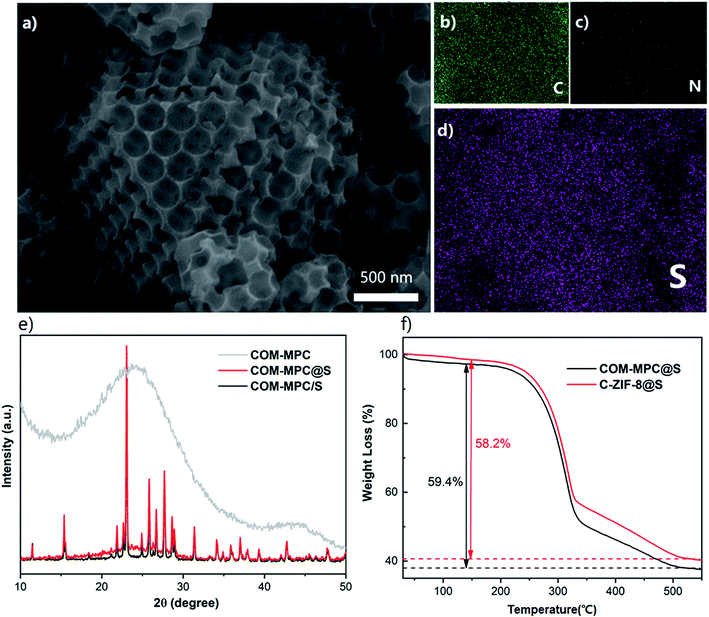
The COM-MPC@S and C-ZIF-8@S composites were prepared by a simple melt-diffusion process. As shown in Fig. 4a, the cuboctahedron shape with ordered macropores of the COM-MPC was well preserved after loading sulfur. Furthermore, a fraction of sulfur coat on the external surface without any aggregation of sulfur being observed and the element mapping (Fig. 4d) illustrate the homogeneous distribution of sulfur. These results indicated that element sulfur was successfully impregnated into porous carbons via capillary forces during the melt-diffusion process. The XRD patterns of the composite (Fig. 4e) further confirmed the incorporation of sulfur. Compared with the COM-MPC/S mixture that was only ground, the hot-melted COM-MPC@S cathode had a broad peak at around 25° corresponding to the amorphous carbon while the diffraction peaks corresponding to sublimed sulfur were still distinct, which indicated that a part of sulfur was embedded in the porous wall, while another part remained on the external surface. The test results of C-ZIF-8@S are displayed in Fig. S4,† which is in good agreement with the COM-MPC@S cathode in terms of sulfur impregnation. To ascertain the sulfur content in these composites, TGA analysis was performed as illustrated in Fig. 4f. The main mass loss in the temperature region from 220 °C to 515 °C was attributed to the thermal escape of sulfur, which can be divided into two different stages. The rapid quality decrease of the sample between 220 °C and 340 °C corresponded to the evaporation of sulfur on the external surface of the host where the sulfur could escape easily, while the slower process between 340 °C and 515 °C was assigned to the sulfur encapsulated in the porous wall limited by the narrow pore size.47 Here, 59.4% sulfur was loaded in the COM-MPC@S composite (58.2% for C-ZIF-8@S), in accordance with the mass ratio during synthesis process.
In order to study the electrochemical performance of the COM-MPC@S cathode, the composite material, conductive agent and binder were mixed in proportion to prepare the working electrode, and the coin cells were assembled using lithium metal as the counter electrode. The cyclic voltammetry curve of the COM-MPC@S cathode for the first three cycles is shown in Fig. 5a. The two reduction peaks at 2.35 V and 2.03 V during the cathodic scan corresponded respectively to the process of S8 ring molecule transforming into soluble Li2Sn (4 ≤ n ≤ 8) and further reducing to insoluble Li2S2/Li2S, while the peak at 2.47 V during the anodic scan corresponded to Li2S2/Li2S being oxidized to S8. In addition, apart from the typical two-step reduction of element sulfur, the potential hysteresis phenomenon that large discharge current retains in the range of 1.5 V to 1.9 V after the second reduction peak was observed. This phenomenon is more common in positive electrode materials with abundant micropores,23,24 where the sulfur needs extra energy to overcome the strong adsorption force caused by the restriction of narrow pore size and the low-order small sulfur molecules (S2–4) are unstable due to their high energy state,23 indicating that the microporous structure of the COM-MPC well limits the sulfur. Furthermore, the curves at different cycles show no obvious change, demonstrating the good electrochemical reversibility and cycle stability of COM-MPC@S materials.
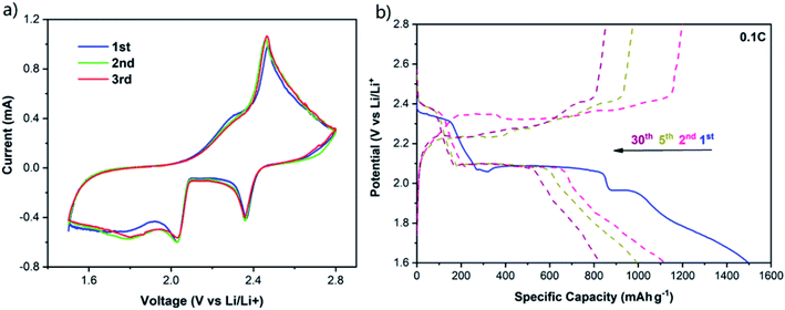 | ||
| Fig. 5 (a) CV curves of the COM-MPC@S cathode at 0.1 mV s−1. (b) Galvanostatic charge/discharge profiles of the COM-MPC@S cathode at 0.1C. | ||
Galvanostatic charge/discharge profiles of the COM-MPC@S cathode at 0.1C is shown in Fig. 5b (the comparison sample is shown in Fig. S5†), and two obvious discharge plateaus and the potential hysteresis phenomenon can be observed, which agrees well with the CV curves. Moreover, the C-ZIF-8@S composite possessed an excellent initial discharge specific capacity of 1306.4 mA h g−1, while the COM-MPC@S cathode with large pores showed a higher capacity of 1498.5 mA h g−1 which was close to 90% of Li–S batteries' theoretical capacity. In the second cycle, the C-ZIF-8@S and COM-MPC@S composites severally exhibited reversible specific capacities of 945 mA h g−1 and 1118.9 mA h g−1, and then decayed to 636.5 mA h g−1 and 828.1 mA h g−1 after 30 cycles, which were 67.4% and 74.0% of their initial values, respectively. The outstanding performances of these two materials benefit first from the highly dispersing sulfur in the porous material and then from the spatial confinement of its micropores and the chemical adsorption of the doping N elements, which can effectively alleviate the dissolution and shuttle of polysulfide ions. Besides, it can be seen that the COM-MPC@S material is superior to the traditional C-ZIF-8@S in terms of the initial capacity and capacity retention rate, proving that the introduction of the macroporous structure effectively improves the performance of the Li–S battery.
To further study the effect of the connected macroporous–microporous structure, the cycle performances of the COM-MPC@S cathode at rates of 0.5C and 1C were tested with C-ZIF-8@S serving as a comparison. At a relatively large rate of 0.5C (Fig. 6a and b), the COM-MPC@S cathode displayed an initial specific capacity of 1341.7 mA h g−1 and still retained a reversible capacity of 707.2 mA h g−1 after 50 cycles. The capacity retention rate within 10–50 cycles was 82.3% with the corresponding coulombic efficiency of above 97%, showing good cycle stability and recoverability. In contrast, the performance of C-ZIF-8@S was slightly worse, demonstrating a lower initial specific capacity of 1171.6 mA h g−1 with only 574.8 mA h g−1 left after 50 cycles, and the capacity retention within 10–50 cycles was 75.8%. When the rate was further increased to 1C (Fig. 6c and d), the performance gap between the two became more obvious. The initial discharge specific capacity of the COM-MPC@S cathode can reach 1221.8 mA h g−1, and a capacity of 608.5 mA h g−1 can be maintained after 50 cycles, while C-ZIF-8@S has only a low capacity of 438.9 mA h g−1 after 50 cycles. In addition, the C-ZIF-8@S electrode produces a huge drop immediately in capacity in the second cycle compared with the initial cycle, while the COM-MPC@S cathode has no difference from the discharge trend at low rates, indicating that the latter is more suitable for cycling under the large rate. The good capacity and stability of the COM-MPC@S cathode at high rates are mainly attributed to the introduction of the ordered macropore structure. The connected macropores promote the unimpeded circulation of the electrolyte in it, better infiltrating the active material, shortening the diffusion path and accelerating the transmission rate of Li+ ions, so it can withstand the charge transmission requirements of large current at high rates. Moreover, a larger specific surface area can expose more pyridine nitrogen/pyrrole nitrogen active sites and hence effectively absorb the polysulfide ions in the reaction process, inhibit their shuttle in the electrolyte and improve the cycle stability of Li–S batteries.
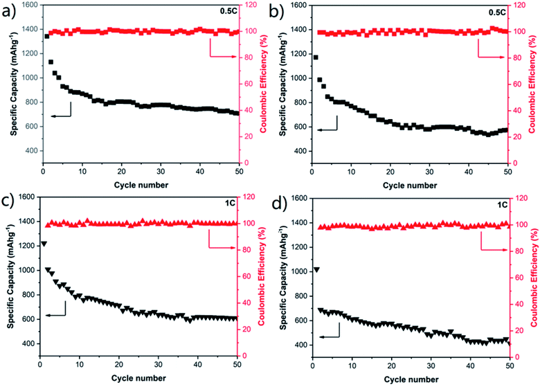 | ||
| Fig. 6 Cycling performances of (a) COM-MPC@S and (b) C-ZIF-8@S composite electrodes at a rate of 0.5C. Cycling performances of (c) COM-MPC@S and (d) C-ZIF-8@S composite electrodes at a rate of 1C. | ||
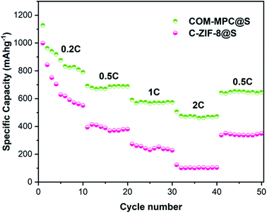
The rate performance of the COM-MPC@S composite was tested, and C-ZIF-8@S was still used as a reference. As shown in Fig. 7, as the current increases, the internal polarization resistance of the battery becomes larger, resulting in a rapid decrease in the output voltage and a gradual decrease in capacity. The COM-MPC@S cathode demonstrated a reversible specific capacity of 688.4 mA h g−1, 573.9 mA h g−1 and 472.3 mA h g−1 at 0.5C, 1C, and 2C, respectively, and back to 652.6 mA h g−1 when the current returns to 0.5C, indicating the good structural stability, electrochemical reversibility and capacity recovery of the COM-MPC host. In contrast, the rate performance of C-ZIF-8@S was slightly worse, possessing a specific capacity of 380.4 mA h g−1 and 227.6 mA h g−1 at the rate of 0.5C and 1C respectively, and only an extremely low capacity of 103.3 mA h g−1 at 2C. Additionally, with the increase in the charge/discharge rate, the gap of capacity released by C-ZIF-8@S and COM-MPC@S composites continuously increased, indicating that the latter has more excellent large rate performance and cycle stability.
To further uncover the charge transport and lithium ion diffusion process at the electrode interface of this hierarchical porous carbon-based material and study its electrical conductivity, electrochemical impedance spectroscopy (EIS) was carried out on the COM-MPC@S composite cathode material that has not discharged, and the C-ZIF-8@S composite participated as a contrast. The results of the Nyquist plot of these two materials are presented in Fig. 8, both of which are composed of a semicircle in the high-frequency region and an inclined straight line in the low-frequency region. The intercept between the plots and the Z′-axis represents the internal resistance Re, which includes the inherent ohmic resistance of the electrode and electrolyte. The Re value of COM-MPC@S and C-ZIF-8@S are 3.54 Ω and 2.54 Ω respectively, indicating the good conductivity of these composites. The diameter of the semicircle in the high-frequency region is related to the charge transfer resistance (Rct), which represents the difficulty of the electrode reaction.48 The Rct value of the COM-MPC@S composite is 74.4 Ω, which is obviously smaller than 85 Ω of the C-ZIF-8@S, proving that the introduction of macropores promotes the infiltration between the electrode material and the electrolyte, resulting in a higher transmission efficiency of lithium ions in the matrix and shortened diffusion distance, making the electrode reaction easier to proceed.
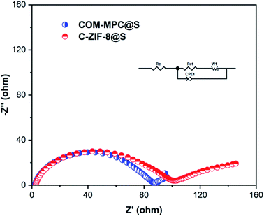 | ||
| Fig. 8 Nyquist plots and the equivalent circuit model (inset) of COM-MPC@S and C-ZIF-8@S composites before discharge. | ||
4 Conclusion
In summary, we have synthesized novel connected ordered macroporous ZIF-8 by a dual solvent-assisted in situ crystallization method within the fcc stacking sphere template, which was then carbonized to prepare COM-MPCs and used as a sulfur host. Due to its unique macro–microporous structure with nitrogen doping, this composite possesses an outstanding capacity and cycling stability. The as-prepared COM-MPC@S cathode delivers a high initial specific capacity of 1498.5 mA h g−1 and a reversible specific capacity of 1118.9 mA h g−1. Apart from that, compared with traditional predominant microporous C-ZIF-8@S, COM-MPC@S exhibits enhanced cycling stability and rate capability. The capacity retention reaches 82.3% within 10th to 50th cycle at 0.5C and still maintains a capacity of 608.5 mA h g−1 after 50 cycles at a higher rate of 1C, with a coulombic efficiency of over 97%. The improved performances can give the credit to the well-defined hierarchical macro–microporous structure of the COM-MPC host, which renders element sulfur enhanced electrical conductance, allows for entrapment of polysulfide intermediates by the confined effect of micropores and chemisorption of doping N atoms, and facilitates electrolyte accessibility and efficient ion transport benefitting from the macroporous structure. These excellent electrochemical properties endow the hierarchical porous carbon materials having connected and ordered macro–micropores with great practical application potential in lithium–sulfur battery systems.Author information
All authors contributed to the preparation of this manuscript. Ji Xinxin and Li Qian contributed equally to this work. Ji Xinxin conceived the idea. Ji Xinxin, Li Qian conducted the experiments, data collection. Yu Haoquan and Hu Xiaolin synthesized C-ZIF-8. Li Buyin and Luo Yuanzheng helped with discussion and explanation of results. Li Buyin and Luo Yuanzheng contributed equally to this work. All authors reviewed the manuscript.Conflicts of interest
There are no conflicts to declare.Acknowledgements
This work was financially supported by the Fundamental Research Funds for the Central Universities (HUST: no. 2016YXMS205), the Creative Technology Project of Hubei Province: no. 2016AAA048, and the scientific research start-up funds of Guangdong Ocean University.References
- A. Fotouhi, D. J. Auger, K. Propp, S. Longo and M. Wild, Renewable Sustainable Energy Rev., 2016, 56, 1008–1021 CrossRef CAS.
- A. Manthiram, Y. Fu, S. H. Chung, C. Zu and Y. S. Su, Chem. Rev., 2014, 114, 11751–11787 CrossRef CAS.
- R. Xu, J. Lu and K. Amine, Adv. Energy Mater., 2015, 5, 1500408 CrossRef.
- S. Q. Luo, W. W. Sun, J. H. Ke, Y. Q. Wang, S. K. Liu, X. B. Hong, Y. J. Li, Y. F. Chen, W. Xie and C. M. Zheng, Nanoscale, 2018, 10, 22601–22611 RSC.
- Z. W. Seh, W. Y. Li, J. J. Cha, G. Y. Zheng, Y. Yang, M. T. McDowell, P. C. Hsu and Y. Cui, Nat. Commun., 2013, 4, 1331–1337 CrossRef.
- C. Hu, H. Chen, Y. Shen, D. Lu, Y. Zhao, A. H. Lu, X. Wu, W. Lu and L. Chen, Nat. Commun., 2017, 8, 479 CrossRef.
- L. N. Wang and H. R. Byon, J. Power Sources, 2013, 236, 207–214 CrossRef CAS.
- Q. Pang and L. F. Nazar, ACS Nano, 2016, 10, 4111–4118 CrossRef CAS.
- R. Demir-Cakan, J. Power Sources, 2015, 282, 437–443 CrossRef CAS.
- J. Hassoun and B. Scrosati, Adv. Mater., 2010, 22, 5198–5201 CrossRef CAS.
- T. Hakari, M. Nagao, A. Hayashi and M. Tatsumisago, Solid State Ionics, 2014, 262, 147–150 CrossRef CAS.
- D. Aurbach, E. Pollak, R. Elazari, G. Salitra, C. S. Kelley and J. Affinito, J. Electrochem. Soc., 2009, 156, A694–A702 CrossRef CAS.
- X. L. Ji, D. Y. Liu, D. G. Prendiville, Y. C. Zhang, X. N. Liu and G. D. Stucky, Nano Today, 2012, 7, 10–20 CrossRef CAS.
- G. He, X. L. Ji and L. Nazar, Energy Environ. Sci., 2011, 4, 2878–2883 RSC.
- X. Ji, K. T. Lee and L. F. Nazar, Nat. Mater., 2009, 8, 500–506 CrossRef CAS.
- L. Ji, M. Rao, H. Zheng, L. Zhang, Y. Li, W. Duan, J. Guo, E. J. Cairns and Y. Zhang, J. Am. Chem. Soc., 2011, 133, 18522–18525 CrossRef CAS.
- J. Z. Wang, L. Lu, M. Choucair, J. A. Stride, X. Xu and H. K. Liu, J. Power Sources, 2011, 196, 7030–7034 CrossRef CAS.
- X. G. Yu, J. Y. Xie, J. Yang, H. J. Huang, K. Wang and Z. S. Wen, J. Electroanal. Chem., 2004, 573, 121–128 CAS.
- G. C. Li, G. R. Li, S. H. Ye and X. P. Gao, Adv. Energy Mater., 2012, 2, 1238–1245 CrossRef CAS.
- J. E. Trevey, C. R. Stoldt and S. H. Lee, J. Electrochem. Soc., 2011, 158, A1282–A1289 CrossRef CAS.
- X. Y. Tao, J. G. Wang, C. Liu, H. T. Wang, H. B. Yao, G. Y. Zheng, Z. W. Seh, Q. X. Cai, W. Y. Li, G. M. Zhou, C. X. Zu and Y. Cui, Nat. Commun., 2016, 7, 11203 CrossRef CAS.
- M. J. Klein, G. M. Veith and A. Manthiram, J. Am. Chem. Soc., 2017, 139, 9229–9237 CrossRef CAS.
- B. Zhang, X. Qin, G. R. Li and X. P. Gao, Energy Environ. Sci., 2010, 3, 1531–1537 RSC.
- S. Xin, L. Gu, N. H. Zhao, Y. X. Yin, L. J. Zhou, Y. G. Guo and L. J. Wan, J. Am. Chem. Soc., 2012, 134, 18510–18513 CrossRef CAS.
- B. Ding, C. Yuan, L. Shen, G. Xu, P. Nie and X. Zhang, Chem.–Eur. J., 2013, 19, 1013–1019 CrossRef CAS.
- C. Zhao, L. Liu, H. Zhao, A. Krall, Z. Wen, J. Chen, P. Hurley, J. Jiang and Y. Li, Nanoscale, 2014, 6, 882–888 RSC.
- Y. Xing, S. Wang, B. Fang, G. Song, D. P. Wilkinson and S. Zhang, J. Power Sources, 2018, 385, 10–17 CrossRef CAS.
- Y. Xing, Y. Wang, C. Zhou, S. Zhang and B. Fang, ACS Appl. Mater. Interfaces, 2014, 6, 2561–2567 CrossRef CAS.
- D. Liu, X. Zhang, Y.-J. Wang, S. Song, L. Cui, H. Fan, X. Qiao and B. Fang, Nanoscale, 2020, 12, 9524–9532 RSC.
- B. Fang, J. H. Kim, M.-S. Kim, A. Bonakdarpour, A. Lam, D. P. Wilkinson and J.-S. Yu, J. Mater. Chem., 2012, 22, 19031–19038 RSC.
- B. Fang, Y. Z. Wei and M. Kumagai, J. Power Sources, 2006, 155, 487–491 CrossRef CAS.
- Y. Xing, B. Fang, A. Bonakdarpour, S. Zhang and D. P. Wilkinson, Int. J. Hydrogen Energy, 2014, 39, 7859–7867 CrossRef CAS.
- B. Fang, M. Kim, J. H. Kim and J.-S. Yu, Langmuir, 2008, 24, 12068–12072 CrossRef CAS.
- B. Fang, J. H. Kim, M.-S. Kim and J.-S. Yu, Acc. Chem. Res., 2013, 46, 1397–1406 CrossRef CAS.
- B. Fang, A. Bonakdarpour, B. A. Pinaud and D. P. Wilkinson, ECS Trans., 2017, 77, 1367–1373 CrossRef CAS.
- W. Xia, A. Mahmood, R. Zou and Q. Xu, Energy Environ. Sci., 2015, 8, 1837–1866 RSC.
- J. K. Sun and Q. Xu, Energy Environ. Sci., 2014, 7, 2071–2100 RSC.
- Y.-J. Li, J.-M. Fan, M.-S. Zheng and Q.-F. Dong, Energy Environ. Sci., 2016, 9, 1998–2004 RSC.
- Z. Q. Wang, B. X. Wang, Y. Yang, Y. J. Cui, Z. Y. Wang, B. L. Chen and G. D. Qian, ACS Appl. Mater. Interfaces, 2015, 7, 20999–21004 CrossRef CAS.
- Y. Yan, M. Shi, Y. Wei, C. Zhao, M. Carnie, R. Yang and Y. Xu, J. Alloys Compd., 2018, 738, 16–24 CrossRef CAS.
- K. Xi, S. Cao, X. Peng, C. Ducati, R. Vasant Kumar and A. K. Cheetham, Chem. Commun., 2013, 49, 2192–2194 RSC.
- K. Shen, L. Zhang, X. D. Chen, L. M. Liu, D. L. Zhang, Y. Han, J. Y. Chen, J. L. Long, R. Luque, Y. W. Li and B. L. Chen, Science, 2018, 359, 206–210 CrossRef CAS.
- J. Cravillon, R. Nayuk, S. Springer, A. Feldhoff, K. Huber and M. Wiebcke, Chem. Mater., 2011, 23, 2130–2141 CrossRef CAS.
- Q. Li, Z. Dai, J. Wu, W. Liu, T. Di, R. Jiang, X. Zheng, W. Wang, X. Ji, P. Li, Z. Xu, X. Qu, Z. Xu and J. Zhou, Adv. Energy Mater., 2020, 1903750, DOI:10.1002/aenm.201903750.
- X. Zhou, L. Chen, W. Zhang, J. Wang, Z. Liu, S. Zeng, R. Xu, Y. Wu, S. Ye, Y. Feng, X. Cheng, Z. Peng, X. Li and Y. Yu, Nano Lett., 2019, 19, 4965–4973 CrossRef CAS.
- D. S. Yu, Y. H. Xue and L. M. Dai, J. Phys. Chem. Lett., 2012, 3, 2863–2870 CrossRef CAS.
- J. Zhang, M. Huang, B. Xi, K. Mi, A. Yuan and S. Xiong, Adv. Energy Mater., 2018, 8, 1701330 CrossRef.
- J. Zhou, R. Li, X. Fan, Y. Chen, R. Han, W. Li, J. Zheng, B. Wang and X. Li, Energy Environ. Sci., 2014, 7, 2715 RSC.
Footnote |
| † Electronic supplementary information (ESI) available. See DOI: 10.1039/d0ra07114e |
| This journal is © The Royal Society of Chemistry 2020 |

