 Open Access Article
Creative Commons Attribution 3.0 Unported Licence
Lichen-like anchoring of MoSe2 on functionalized multiwalled carbon nanotubes: an efficient electrode for asymmetric supercapacitors†
Swapnil S. Karadea,
Ajaysing S. Nimbalkarbc,
Jeong-Hyun Euma and
Hansung Kim *a
*a
aElectrochemical Energy Laboratory, Department of Chemical and Biomolecular Engineering, Yonsei University, 50 Yonsei-ro, Seodaemun-gu, Seoul-03722, Republic of Korea. E-mail: elchem@yonsei.ac.kr
bKorea Research Institute of Chemical Technology, Yusong-gu, Republic of Korea
cUniversity of Science and Technology, Daejeon, Republic of Korea
First published on 4th November 2020
Abstract
In the present study, we have developed a composite electrode of MSNT using a simple and scalable two-step scheme to synthesize a composite electrode material comprising MoSe2/multiwalled carbon nanotubes (MoSe2/MWCNTs) for supercapacitor applications. First, a MWCNT thin film was deposited on a stainless steel substrate by using a “dip and dry” coating technique. Subsequently, MoSe2 was deposited onto the MWCNT thin film using the successive ionic layer adsorption and reaction method. The lichen-like growth of MoSe2 on the MWCNT network provided dual charge storage and an effective ion transfer path. The composite electrode of MSNT has been studied systematically with different electrolytes and concentrations of electrolyte. As a result, the MoSe2/MWCNT (MSNT) electrode exhibited excellent electrochemical properties such as a specific capacity of 192 mA h g−1 and a capacitance retention of 88% after 2000 cycles in 1 M LiCl electrolyte. The results demonstrated the huge potential of the MSNT composite electrode for practical application in supercapacitors. The aqueous symmetric cell fabricated using the MSNT composite as both the anode and cathode showed an energy density of 17.9 W h kg−1. Additionally, the energy density improved by designing an asymmetric device of MSNT//MnO2 and notably, it reveals two-fold improvement in the energy density compared to a symmetric MSNT cell. The MSNT//MnO2-based asymmetric cell exhibited a maximum specific capacitance of 112 F g−1 with a high energy density of 35.6 W h kg−1.
1. Introduction
Carbon-based materials such as carbon nanotubes (CNTs), graphene, reduced graphene oxide (rGO), and activated carbon (AC) demonstrate electrochemical double-layer capacitive behavior. These materials exhibit large surface areas, less degradation, high stability, and good electrical conductivity. However, carbon-based materials suffer from low capacitance.1,2 Nanostructured inorganic and organic materials such as metal oxides/hydroxides, metal chalcogenides, and conducting polymers show pseudocapacitive charge storage behavior.3–6 Recently, metal phosphides are coming into the picture of supercapacitive materials with a superior electrochemical performance.7–9 Zhou et al.7 developed a pseudocapacitive Ni2P nanosheet directly grown on Ni foam via phosphorization. The Ni2P electrode shows remarkable specific capacitance of 2141 F g−1 with a good retention of 1109 F g−1 even at a high current density of 83.3 A g−1. Further, an asymmetric device of Ni2P as a positive electrode and activated carbon (AC) as a negative electrode shows significant results with a specific capacitance of 96 F g−1 and energy density of 26 W h kg−1. Zhang et al.8 fabricate a high-performance asymmetric supercapacitor using bimetallic phosphide of CoxNi1−xP on carbon nanofibers (CNF) as a positive electrode and AC as negative electrode. It reveals significant electrochemical properties with a potential window of 1.4 V, specific capacitance of 85 F g−1 and energy density of 32.2 W h kg−1. Also, Zhang et al.9 reported CoP/CNF prepared by using chemical reduction and used as a negative electrode to made a high-performance asymmetric supercapacitor with a NiP/CNF as a positive electrode. Notably, the asymmetric device delivers maximum specific capacitance of 164 F g−1 with a high energy density of 56 W h kg−1 and long-term stability up to 5000 cycles. As compared to carbon-based materials, these materials show high capacitance; however, they degrade during the charge–discharge process, and hence show poor cycling stability.3–6,10,11 Therefore, various nanocomposites have been prepared in order to overcome the limitations and improve the electrochemical performance of single materials.In the last decade, metal dichalcogenides have gained significant attention in the field of energy storage and conversion owing to their chemical, physical, optical, electrical, and mechanical properties.12–16 In addition, their layered graphene-like structure, higher electrical conductivity than that of metal oxides, multivalent oxidation states, earth abundance, and nontoxicity make them promising candidates for commercial applications.5,17,18 Molybdenum- and tungsten-based chalcogenides are two-dimensional (2D) materials with nanosheets and flower-like nanostructures.19,20 Soon and Loh et al. demonstrated the use of transition metal chalcogenide-based materials for supercapacitor applications. In 2007, MoS2 nanowall films with an electrochemical double-layer capacitance were reported.21 Since then, various developments have been made in the preparation of molybdenum- and tungsten-based chalcogenides for supercapacitor applications.22–30
At present, numerous reports are available on the use of MoS2, MoSe2, and MoTe2 as supercapacitor electrodes. Balasingam et al. synthesized few-layered MoSe2 nanosheets for supercapacitor applications by using a hydrothermal method. When used as an electrode, these nanosheets exhibited a significant specific capacitance of 199 F g−1 at a scan rate of 2 mV s−1 in 0.5 M H2SO4 as the electrolyte.31 The authors extended their work by developing complex MoSe2/rGO nanosheets and obtained a higher specific capacitance of 211 F g−1 at the scan rate of 2 mV s−1.32 In addition, Huang et al. reported a simple hydrothermal strategy for the synthesis of MoSe2 and its direct deposition on Ni foam. The resulting MoSe2/Ni foam electrode showed a high capacitance of 744 F g−1 and the faradaic charge storage behavior in 6 M KOH as the electrolyte.33 A binder-free approach based on the highly efficient electrodeposition method was successfully utilized for the deposition of 2D MoSe2 on a Ni foam.34 The resulting electrode showed a battery-type charge storage behavior with a capacity of 548 mA h g−1. Furthermore, a highly porous net-like acetylene black-supported MoSe2 composite electrode was synthesized by using the hydrothermal method. The MoSe2-acetylene black composite electrode showed an outstanding specific capacitance of 2020 F g−1 and an excellent cyclic retention of 107% after 1500 cycles.35 In addition to bare MoSe2 and carbon–MoSe2 composites, high-performance heterostructural composites such as NiSe@MoSe2 and CoNi2S4–graphene–MoSe2 have also been reported.36,37
Developing a hybrid nanostructure with a carbon matrix is an efficient approach to improve the performance of MoSe2 electrodes. Owing to their one-dimensional (1D) structure, large surface area, good chemical stability, and mechanical flexibility, multiwalled carbon nanotubes (MWCNTs) are considered as the most promising matrix materials for supporting the host materials.38–40 Furthermore, the 1D structure of MWCNTs provides good electrical conductivity and efficient electron transfer pathways. In addition, the MWCNT surface reduces the aggregation of the host material. Therefore, in this study, we developed a simple, scalable, and binder-free two-step chemical process. A MWCNT thin film was fabricated using the “dip and dry” coating method followed by the deposition of MoSe2 using the successive ionic layer adsorption and reaction (SILAR) method. The structure and morphology of the MoSe2/MWCNT (MSNT) composite thin film were analyzed. The charge storage behavior of the composite thin film in various electrolytes (with different concentrations) was investigated. The MSNT composite electrode showed enhanced electrochemical properties compared to the pristine MoSe2 electrode, suggesting that the MSNT composite thin film possesses great potential for application as an electrode material for supercapacitor devices. The symmetric and asymmetric cells demonstrated good electrochemical performance.
2. Experimental
2.1. Materials
Stainless steel (SS) strips (grade 306) were used as the substrate. All the commercially available analytical reagents, i.e., ammonium heptamolybdate [(NH4)6Mo7O24], citric acid (C6H8O7), sodium borohydride (NaBH4), Na2SO3 (sodium sulfite), and selenium (Se) metal powder were purchased from Sigma-Aldrich and used without further treatment. Chemical vapor-deposited MWCNTs were purchased from Nano Amor (Houston, USA). To prepare all the solutions, double-distilled water (DDW) was used as the solvent in all the experiments. The sodium selenosulfite (Na2SeSO3) precursor was prepared using a previously optimized procedure.41 A bath containing 5 g of Se mixed with 15 g of Na2SO3 in 200 mL of DDW was refluxed at 90 °C for 9 h to obtain a clear solution of Na2SeSO3. The prepared Na2SeSO3 solution was then stored in an airtight container and used as the Se source.2.2. Synthesis of the MoSe2/MWCNTs composite thin film
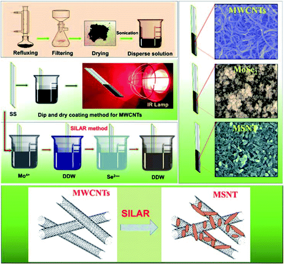
First, functionalized MWCNTs were deposited on the SS substrate.6 In brief, the commercially available MWCNTs were purchased from Nano Amor (Houston, USA) and were then refluxed with H2O2 at 90 °C for 48 h to remove amorphous carbon derivatives and generate oxygenated functional groups. The obtained filtrate was repeatedly rinsed with DDW and dried overnight in an oven at 60 °C. The functionalized MWCNTs (0.250 g) were mixed in a 50 mL solution of DDW and the Triton X-100 surfactant (Tritonx, 100![[thin space (1/6-em)]](https://www.rsc.org/images/entities/char_2009.gif) :
:![[thin space (1/6-em)]](https://www.rsc.org/images/entities/char_2009.gif) DDW = 1
DDW = 1![[thin space (1/6-em)]](https://www.rsc.org/images/entities/char_2009.gif) :
:![[thin space (1/6-em)]](https://www.rsc.org/images/entities/char_2009.gif) 100). The obtained solution was sonicated for 1 h to obtain a stable dispersion. A mirror-polished SS substrate was vertically immersed in the solution for 10 s for the adsorption of the MWCNTs onto the SS substrate; the SS was then dried under an infrared (IR) lamp to evaporate the solvent. This process was repeated 12 times to obtain a terminal thickness of MWCNTs on the SS and to form adequate nucleation sites with a web-like porous nanonetwork and large surface area for the deposition of MoSe2.
100). The obtained solution was sonicated for 1 h to obtain a stable dispersion. A mirror-polished SS substrate was vertically immersed in the solution for 10 s for the adsorption of the MWCNTs onto the SS substrate; the SS was then dried under an infrared (IR) lamp to evaporate the solvent. This process was repeated 12 times to obtain a terminal thickness of MWCNTs on the SS and to form adequate nucleation sites with a web-like porous nanonetwork and large surface area for the deposition of MoSe2.
In the second step, the MoSe2 thin film was deposited by alternately immersing the SS and precoated SS/MWCMT substrates in separate cationic and anionic precursors at ambient temperature. The first beaker consisted of 20 mL of 25 mM ammonium heptamolybdate as the source of Mo ions with 5 mL of 1 M citric acid and 1 mL of 1% sodium borohydride as reducing agents. The second beaker was filled with DDW to remove the loosely bound complexed cation species. The third beaker contained 25 mL of a 0.25 N Na2SeSO3 solution with 1 mL of a 1% sodium borohydride solution as the reducing agent. The fourth beaker was filled with DDW for the second rinsing to remove the loosely bound molecules and unreacted ion species. The SS and precoated MWCNT substrates were sequentially immersed in the four beakers for 20, 10, 20, and 10 s, representing one complete SILAR cycle. Twenty consecutive SILAR cycles were sufficient to obtain a MoSe2 thin film with a desired thickness. The dipping area 3 cm × 3 cm of the stainless-steel sample was coated by MoSe2 and MSNT thin films. The adhesion of MWCNT thin film is quite good enough to stable during SILAR process. Fig. S1† shows deposition of MSNT composite thin film which clearly shows MWCNT has good adhesion on SS substrate which does not lose a physical contact during SILAR process (ESI S1†). Basically, weight difference method was used to measure the loading of MoSe2 and MSNT thin films.
| m = m2 − m1 | (1) |
In which, ‘m’ is loading of active materials, ‘m1’ is weight of substrate before deposition and ‘m2’ is weight of substrate after deposition of thin films. Fig. 1 shows the schematic of the preparation of the MWCNTs, MoSe2, and MSNT thin films. The samples were characterized using various analytical techniques (ESI S2†).
2.3. Electrochemical setup
The prepared MoSe2 and MSNT electrodes were used as the working electrodes and a Pt wire and Ag/AgCl as the counter and reference electrodes, respectively. The electrochemical properties of the electrodes were investigated using a potentiostat/galvanostat (PARSTAT 4000, Princeton Applied Research, USA). The mass loading played an important role in the evaluation of the specific electrochemical parameters of the electrodes. The weights of the MoSe2 and MSNT electrodes were 0.23 and 0.40 mg cm−2, respectively.3. Results and discussion
3.1. Reaction kinetics
Lichen-like MoSe2 nanoparticles were deposited on the MWCNT surface via the electrostatic adsorption of cations and their reaction with anions. Initially, (NH4)6Mo7O24 was used as the Mo source, which dissociated in DDW to form heptamolybdate ions.42| (NH4)6Mo7O24 → 6NH4+ + Mo7O246− | (2) |
After the addition of citric acid, these heptamolybdate ions formed a complex with citrate ions [C3H5O(COO)33−], as shown below :43
| Mo7O246− + 2C3H5O(COO)33− → [Mo–2C3H5O(COO)3] + 12O2 | (3) |
NaBH4 (reducing agent) reduced the Mo6+ ions in the precursor to Mo4+ according to the following reaction:39,41,43
| [Mo–2C3H5O(COO)3] + 2BH4− + 2H2O → Mo4+ + 2C6H8O7 + 2BH3 + O2↑ | (4) |
The bare SS and MWCNT-coated SS substrates were immersed in the aforementioned solution for the adsorption of Mo4+ ions.
The dissociation of Na2SeSO3 produced Na+and SeSO32−, which were further reduced in the presence of NaBH4 (reducing agent) to form Se2− ions.
| SeSO32− + 2BH4− → Se2− + 2BH3 + H2↑ + SO32− | (5) |
Finally, the Mo4+ ion-adsorbed bare SS and MWCNT-coated SS substrates were immersed in the aforementioned solution containing Se2− ions to form MoSe2.
| Mo4+ + 2Se2− → MoSe2 | (6) |
The aforementioned process was repeated several times by immersing the bare SS and MWCNT-coated SS substrates in the respective solutions (Mo4+ and Se2−) to deposit a uniform and well-adhering thin layer of MoSe2 on the substrates.
3.2. Structural analysis
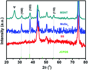
The structures of the MSNT composite and MoSe2 thin films were analyzed using wide-angle X-ray diffraction (XRD) (Fig. 2). The films showed major diffraction peaks at 2θ = 31.4°, 37.8°, and 55.8° corresponding to the (100), (103), and (110) planes of hexagonal MoSe2 (JCPDS No. 87-2419), respectively, while the other peaks listed in the JCPDS card could not be observed because of their low intensity and the relatively high-intensity peaks of the SS substrate. Furthermore, the broad peak observed at 2θ = 26° in the XRD pattern of the MSNT thin film denoted by Ψ was attributable to the characteristic peak of the graphitic carbon of the MWCNTs. The surface elemental compositions of the thin films were analyzed using X-ray photoelectron spectroscopy (XPS). Fig. 3a shows the XPS survey profile of the MSNT composite film. As can be observed from the figure, the film showed peaks corresponding to the Se 3d, Mo 3d, and C 1s orbitals. This further confirmed the formation of the MSNT composite thin film. Fig. 3b shows the core C 1s profile of the film. Two prominent peaks were observed at the binding energies of 284.1 and 286.3 eV corresponding to the graphitic carbon of the MWCNTs and the carbon–oxygen bonds, respectively. The narrow-scan Mo 3d XPS profile of the film (Fig. 3c) showed two distinct peaks at 234.2 and 237.3 eV, indicating that the oxidation state of Mo was 4+.32,39,44–46 In addition, Fig. 3d shows the Se 3d XPS profile of the film. The Se 3d peak of the composite film could be deconvoluted into two peaks at 55.2 and 56 eV, indicating that the oxidation state of Se was 2−.32,36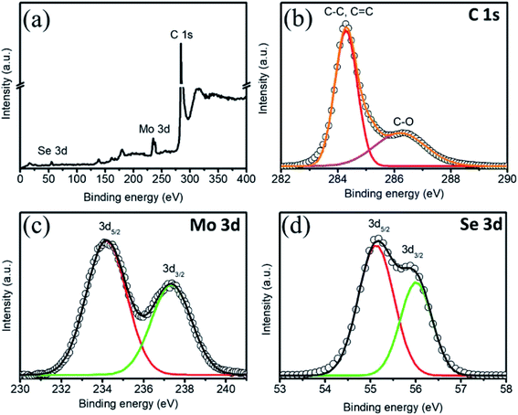 | ||
| Fig. 3 (a) XPS profile of the MSNT composite. Core-level (b) C 1s, (c) Mo 3d, and (d) Se 3d XPS profiles. | ||
3.3. Surface morphology
The surface microstructure of a material significantly affects its charge storage capacity. Fig. 4a shows the microscopic image of the surface of the MWCNT thin film deposited on the SS substrate. Owing to its uniform network-like structure, the MWCNT thin film showed a large surface area and 1D conduction path for electron transfer. The successive cation adsorption and anion reaction resulted in the colonial growth of MoSe2 nanoparticles on the MWCNT thin film, as shown in Fig. 4b and c. Electrodes with a porous structure show large surface area and numerous active sites for interaction with electrolyte ions, and hence offer significant storage ability.47 In the MSNT composite thin film, the lichen-like growth of MoSe2 on the MWCNTs (Fig. 4d and e) reduced the ion diffusion path length and exhibited strong interfacial conjugation. In addition, the porous structure of the MSNT composite provided large effective surface area for the interaction of the electrolyte ions during the electrochemical process, which in turn improved the electrochemical performance of the composite. Fig. 3f shows the energy-dispersive spectroscopy (EDS) mapping of the MSNT composite thin film, which revealed that the film consisted of 72.6% C, 8.8% Mo, and 18.6% Se, confirmed the formation of the MoSe2/MWCNT composite structure.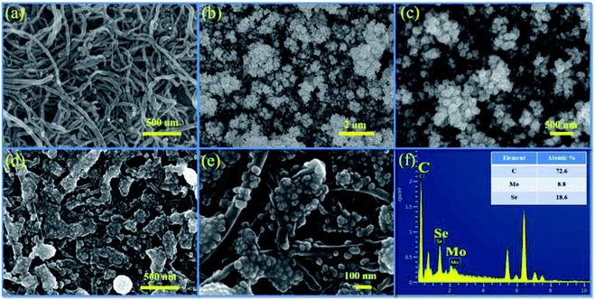 | ||
| Fig. 4 FESEM images of (a) MWCNTs, (b and c) MoSe2, and (d and e) the MSNT composite thin film at different magnifications; and (f) EDS mapping of the MSNT composite thin film. | ||
The transmission electron microscopy (TEM) image of the MSNT composite is shown in Fig. 5a. It clearly reveals the lichen-like growth of MoSe2 nanoparticles on the MWCNTs. The oxygenated functional groups generated during the reflux of the MWCNTs with H2O2 acted as active sites for the growth of MoSe2 on the MWCNTs. Fig. 5b shows the high-magnification TEM image of the MSNT composite film. The lattice fringes with the interplanar spacings of 0.29 nm and 0.24 nm correspond to the (002) plane of graphitic carbon in the MWCNTs and the (103) plane of the hexagonal MoSe2 crystal, respectively (Fig. 5c and d). The selected area electron diffraction (SAED) pattern of the composite film showed concentric rings, indicating its polycrystalline nature (Fig. 5e). The elemental distribution of the MSNT composite sample was analyzed by obtaining its energy-filtered TEM (EFTEM) images (Fig. 5f–i), which confirmed the formation of the MSNT composite.
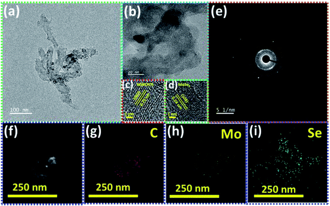 | ||
| Fig. 5 (a) TEM and (b–d) high-resolution TEM images of the MSNT film with the corresponding enlarged view of the lattice fringes, (e) SAED pattern and (f–i) EFTEM mapping of the MSNT film. | ||
3.4. Electrochemical analysis
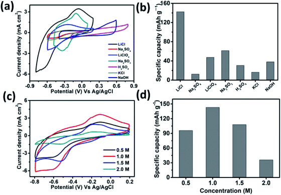
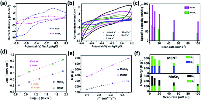
The performance of the MSNT electrode was analyzed using a conventional three-electrode system in a suitable electrolyte with an optimum concentration. Aqueous LiCl, Na2SO4, LiClO4, Na2SO3, H2SO4, KCl, and NaOH (1 M) were used as the electrolytes at a constant scan rate of 20 mV s−1 (Fig. 6a) under Ag/AgCl as reference electrode. The low thermodynamic stability of water is a major disadvantage for aqueous electrolytes.48 The thermodynamic stability of water under the potential limit varies as a function of the pH of the electrolyte solution. Therefore, the cyclic voltammetry (CV) curves of the MSNT electrode showed different potential windows for different electrolytes (Fig. 6a). Fig. 6b shows the specific capacitance values of the electrodes in the different electrolytes used. The aqueous 1 M LiCl electrolyte exhibited the highest specific capacity of 142 mA h g−1 at the scan rate of 20 mV s−1. It is well-known that the specific capacity of an electrode is a charge-dependent quantity, and the electrolyte concentration determines the quantity of charges. Hence, the effect of the LiCl concentration (0.5–2 M) on the CV performance of the MSNT composite electrode at a fixed scan rate of 20 mV s−1 was investigated (Fig. 6c). Fig. 6d shows the effect of the LiCl concentration on the specific capacity of the MSNT composite electrode. As can be observed from the figure, the specific capacity of the electrode increased with an increase in the LiCl concentration from 0.5 to 1 M. With a further increase in the LiCl concentration, the specific capacity of the electrode decreased. This is because at higher LiCl concentrations, the channels within the electrode layer were effectively consumed by the electrolyte ions. The ion activity decreased with an increase in the LiCl concentration because of the deceleration of the water hydration reaction, which reduced the mobility of the electrolyte ions.6,46 The optimum LiCl concentration was found to be 1 M. This concentration was used for the electrochemical analyses of the MoSe2 and MSNT thin film electrodes.The CV curves of the MoSe2 and MSNT electrodes at the fixed scan rate of 20 mV s−1 and over the potential range of −0.8–0.2 V vs. Ag/AgCl are shown in Fig. 7a. The MSNT electrode showed higher current distribution than the MoSe2 electrode because of the synergistic effect and good interfacial conjugation between MoSe2 and the MWCNTs. In the 1 M aqueous LiCl electrolyte, the MoSe2 and MSNT electrodes showed a faradaic charge storage behavior characterized by two distinguishable oxidation and reduction peaks. Fig. 7b shows the CV curves of the MSNT composite electrode at different scan rates ranging from 5 to 100 mV s−1. The CV curves of the bare MoSe2 electrode is shown in the ESI S3 (Fig. S2†). The current distribution under the CV curves of both the electrodes increased with an increase in the scan rate, indicating the capacitive nature of the electrodes. In both the electrodes, two charge storage processes occurred during the CV cycling, as indicated by the shape of the CV curves of the electrodes.49 One of these processes could be attributed to the surface adsorption at the interface between the electrode and the electrolyte. A double layer was formed at the electrode/electrolyte interface.
| (MoSe2)surface + xLi+ + xe− ⇌ (Lix–MoSe2)surface | (7) |
The second process corresponded to the reversible faradaic reaction based on the intercalation/deintercalation of Li-ion species.
| MoSe2 + xLi+ + xe− ⇌ LixMoSe2 | (8) |
Thus, the electrochemical properties of these electrodes were achieved by utilizing the overall mass of the electrode material through the surface adsorption and intercalation processes. Fig. 7c shows the correlation between the gravimetric capacity and scan rate for both the electrodes. The MSNT composite electrode showed the maximum capacitance, which was more than two times higher than that of the bare MoSe2 electrode. The capacitance decreased with an increase in the scan rate. At higher scan rates, the ion concentration on the surface of the electrode decreased with an increase in the current, and the ions diffused slowly during the charge–discharge process. In addition, a decrease in the capacitance was observed with an increase in the scan rate because the inner active sites of the electrode could not be sufficiently utilized and could not sustain the complete intercalation/deintercalation process at high scan rates because of time constraints.50 The unique nanostructure with lichen-like MoSe2 on the 1D porous MWCNT network facilitated rapid ion/electron transfer for the intercalation/deintercalation of ions and induced a strong synergistic effect, thus improving the electrochemical properties of the MSNT composite electrode.51 Thus, a very high capacitance of 690 F g−1 was obtained at a low scan rate of 5 mV s−1 because of the effective utilization of all the active sites. The charge storage mechanisms of the electrodes were examined by obtaining their CV curves. The relationship between the current and scan rate can be expressed as follows.52
| I = aνb | (9) |
| Qt = Qs + Qd | (10) |
Considering the semi-infinite linear diffusion, the Qs of the electrodes could be determined by plotting the graph of Qt as a function of the reciprocal square root of the scan rate, as shown in Fig. 7e.
| Qt = Qs + cv−1/2 | (11) |
The surface capacitive and diffusion-controlled charges contributed to the total charge stored by the MoSe2 and MSNT electrodes (Fig. 7f), indicating that the charge storage mechanisms of the electrodes were mainly governed by their redox reactions.
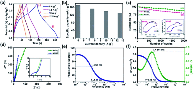
The correlation between the potential of the electrodes and time at the constant current densities of 2–5 mA cm−2 was investigated by obtaining their galvanostatic charge–discharge (GCD) curves. Fig. 8a shows the GCD curves of the MSNT composite electrode. The deviated triangular shape of the curves was due to the faradaic charge storage behavior of the MSNT electrode. In addition, the discharge curve of the electrode could be divided into three parts (Fig. 8a)—(I) an initial potential drop due to the internal resistance of the electrode, (II) a linear deviation because of the charge separation due to the non-faradaic reaction at the interface between the electrode and the electrolyte, and (III) an inclined aberration indicating the faradaic charge storage caused by the reversible intercalation/deintercalation of Li+ ions.53–55 Fig. 8b shows the specific capacities of the MSNT electrode at various current densities, as calculated from its GCD curves. The electrode showed a maximum specific capacity of 171 mA h g−1 at 5 A g−1 and could retain a specific capacity of 130 mA h g−1 at a high current density of 12.5 mA h g−1.
Long-term electrochemical stability is a prerequisite for realizing the practical applications of an electrode. The stability of the MSNT electrode was investigated over 2000 CV cycles at a fixed scan rate of 100 mV s−1 in a 1 M aqueous LiCl electrolyte. Fig. 8c shows the capacity retention of the electrodes over 2000 CV cycles. The MSNT composite electrode showed a capacity retention of 88%, which was higher than that of the bare MoSe2 electrode (80%). The improved stability of the MSNT electrode compared to that of the bare MoSe2 electrode can be attributed to the strong synergistic effect and interfacial conjugation between MoSe2 and the MWCNTs.
Electrochemical impedance spectroscopy (EIS) was used to analyze the capacitive and resistance parameters of the electrodes over the frequency range of 0.1 mHz to 10 kHz at the bias potentials of 0 and 10 mV. Fig. 8d shows the imaginary (Z′′) and real (Z′) parts of the impedance of the MoSe2, and MSNT electrodes. The Nyquist plots of the electrodes showed an intercept with a semicircular arc in the high-frequency region and a straight line in the low-frequency region. The non-zero intercept on the real-axis indicates the equivalent series resistance (Rs), which is the combination of the solution resistance, internal resistance of the active electrode, and the resistance between the active electrode and the current collector. The semicircle corresponds to the faradaic reversible reaction that occurs during the charge storage and the diameter of the semicircle indicates the charge transfer resistance (Rct) associated with the electrode parallel to the double-layer capacitor (Cdl). The Rs and Rct values of the MoSe2, and MSNT electrodes were 0.95 and 0.41; and 2.71 and 2.01 Ω respectively. These considerably small Rs and Rct values indicate an intimate interfacial contact between the electrode and the Li+ ions in the electrolyte.55,56
The frequency-dependent phase angles of the electrodes were determined by obtaining their Bode plots (Fig. 8e). The phase angle of the MSNT electrode increased with a decrease in the frequency and became approximately −90° as the frequency approached the minimum value. This indicates that the MSNT electrode showed a capacitive behavior of the MSNT electrode.57–59 Additionally, the steeply oblique line at low frequency region suggests the MSNT electrode reveals rapid response of electrolyte ion diffusion during charge–discharge.59 Furthermore, the ideal capacitive behavior of the electrode could be assessed by determining the frequency at which the phase angle crossed 45°.58 The MSNT electrode exhibited a frequency of 3.89 Hz when the phase angle crossed 45°, indicating a capacitive behavior with rapid frequency response. Furthermore, the capacitive performance of the electrode could be evaluated by considering the real and imaginary parts of its capacitance with respect to the frequency:
| C(ω) = C′(ω) − jC′′(ω) | (12) |
 | (13) |
 | (14) |
3.5. Symmetric and asymmetric supercapacitor cell
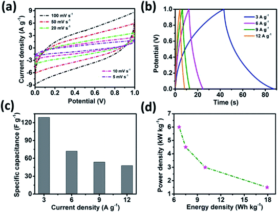
The potential of the MSNT composite electrode for supercapacitor applications was evaluated by fabricating a symmetric supercapacitor cell. The symmetric cell was fabricated using the MSNT composite as both the cathode and anode separated by a Whatman filter paper soaked with 1 M aqueous LiCl as the electrolyte. Fig. 9a shows the CV curves of the cell at scan rates in the range of 5–100 mV s−1 over the potential window of 0–1 V. These curves indicated that the cell showed a pure capacitive behavior. The shape of the CV curves remained almost constant at different scan rates, indicating that the cell showed significant reversibility. Furthermore, the GCD plots of the MSNT symmetric cell at different current densities (3–12 A g−1) are shown in Fig. 9b. The MSNT symmetric cell delivered a maximum specific capacitance of 129 F g−1 at 3 A g−1 (Fig. 9c). The Ragone plots of the cell showing the correlation between its specific energy and specific power are shown in Fig. 9d. The MSNT symmetric cell delivered a significant specific energy of 17.9 W h kg−1 at a specific power of 1.5 kW kg−1. Table 1 lists the specific capacitance, specific energy, and specific power of the MSNT symmetric cell.| Current density (A g−1) | Specific capacitance (F g−1) | Energy density (W h kg−1) | Power density (W kg−1) |
|---|---|---|---|
| 2 | 129 | 17.9 | 1500 |
| 6 | 72 | 10 | 3000 |
| 9 | 54 | 7.5 | 4500 |
| 12 | 48 | 6.7 | 6000 |
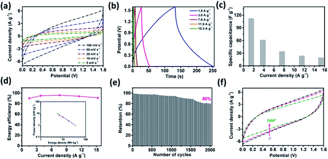
An asymmetric supercapacitor cell was employed to achieve a high energy density over a wide working potential window. A MnO2 thin film was used as the positive electrode to fabricate the MSNT//MnO2 asymmetric supercapacitor.65 The charge contribution of the positive (MnO2) and negative (MSNT) electrodes (CV curves) and the potential stability of the asymmetric cell (GCD plots) are shown in Fig. S3 (ESI S4†). The CV curves of the cell at different scan rates (5–100 mV s−1) are shown in Fig. 10a. The asymmetric cell showed a wide potential window of 1.6 V with no significant polarization. In addition, the shape of the CV curves remained unchanged at high scan rates, indicating the excellent rate capability of the fabricated asymmetric cell. Fig. 10b shows the GCD plots of the MSNT//MnO2 asymmetric cell at different current densities ranging from 1.5 to 15.3 A g−1. The specific capacitance of the cell is shown in Fig. 10c. The maximum specific capacitance of 112 F g−1 was achieved at the current density of 1.5 A g−1. The cell retained a specific capacitance of 19 F g−1 at 15.3 A g−1. The inset of Fig. 10d shows the Ragone plot (specific energy vs. specific power) of the cell. The MSNT//MnO2 cell showed a maximum specific energy of 35.6 W h kg−1 at the power density of 964 W kg−1 and maintained a significant specific energy of 5.7 W h kg−1 even at the high power density of 9327 W kg−1. The asymmetric cell showed a significantly higher specific energy than the symmetric MSNT supercapacitor cell because of its wide working potential. The MSNT//MnO2 asymmetric cell could retain up to 90–96% of its energy efficiency (Fig. 10d). This indicated that the asymmetric cell showed minimum energy loss during the discharging process. Table 2 lists the specific capacitance, specific energy, and specific power of the MSNT/MnO2 asymmetric cell. The long-term cycling stability of the cell was evaluated by obtaining its CV curves at a fixed scan rate of 100 mV s−1 for 2000 cycles (Fig. 10e). The MSNT//MnO2 asymmetric cell could retain 80% capacitance after 2000 cycles. The effect of cycling on the CV curves of the cell is shown in Fig. 10f. The area of the CV curve decreased with an increase in the number of cycles because of the degradation of the electrode material during cycling. Table 3 summarize the electrochemical performance of the MnO2//MSNT asymmetric supercapacitor cell and cells from literature.7–9,66–76
| Current density (A g−1) | Specific capacitance (F g−1) | Energy density (W h kg−1) | Power density (W kg−1) |
|---|---|---|---|
| 1.5 | 112 | 35.6 | 964 |
| 3.8 | 62 | 17.8 | 2347 |
| 7.6 | 34 | 9.9 | 4752 |
| 11.5 | 24 | 6.8 | 6994 |
| 15.3 | 19 | 5.7 | 9327 |
| Cell configuration | Electrolyte | Cell potential (V) | Specific capacitance (F g−1) | Energy density (W h kg−1) | Stability retention@cycles | Ref. |
|---|---|---|---|---|---|---|
| MnO2//MSNT | 1 M LiCl | 1.6 | 112 | 35.6 | 80%@2000 | This work |
| Ni2P//AC | 6 M KOH | 1.4 | 96 | 26 | 91%@5000 | 7 |
| NiCo2O4-rGO//AC | 1 M NaOH | 1.7 | — | 12 | — | 66 |
| NiCo2O4/AC | 1 M NaOH | 1.7 | — | 17.72 | 100%@2000 | 67 |
| RuCo2O4//AC | 2 M KOH | 1.4 | 133 | 32.6 | 82%@2500 | 68 |
| PPy-NTs//N-CNT | 1 M H2SO4 | 1.4 | 109 | 28.95 | 90%@2000 | 69 |
| Co(OH)2//GO | 1 M KOH | 1.2 | 59 | 11.9 | — | 70 |
| Ni(OH)2-CNT//rGO | 1 M KOH | 1.8 | 78 | 35.24 | — | 71 |
| ZnCo2O4//AC | 3 M KOH | 1.6 | 82 | 27.78 | 178%@2000 | 72 |
| NoCo2S4//AC | 3 M KOH | 1.6 | 72 | 25.5 | 86%@4000 | 73 |
| α-NiMoO4//rGO | 3 M KOH | 1.1 | 73 | 12.31 | 85%@2000 | 74 |
| NaMnO2//AC | 0.5 M Na2SO4 | 1.9 | 39 | 19.5 | 97%@10![[thin space (1/6-em)]](https://www.rsc.org/images/entities/char_2009.gif) 000 000 |
75 |
| Co0.1Ni0.9P//AC | 2 M KOH | 1.4 | 119 | 32.2 | 72%@10![[thin space (1/6-em)]](https://www.rsc.org/images/entities/char_2009.gif) 000 000 |
8 |
| FeCo2O4//AC | 6 M KOH | 1.4 | 88 | 24 | 94%@5000 | 76 |
| NiP-CNT//CoP-CNT | 2 M KOH | 1.4 | 151 | 41.1 | 70%@10![[thin space (1/6-em)]](https://www.rsc.org/images/entities/char_2009.gif) 000 000 |
9 |
4. Conclusion
In this study, we developed a novel simple, scalable, and efficient approach to prepare composite electrodes with excellent charge storage performance. We synthesized MSNT composite thin films using the SILAR method for supercapacitor applications. MoSe2 (lichen-like growth) was deposited on a MWCNT nanonetwork, and the resulting MSNT film showed excellent electrochemical properties such as a specific capacity of 192 mA h g−1 and a cyclic stability of 88%. This excellent electrochemical performance of the composite film can be attributed to the large surface area of the MWCNT nanonetwork with a good conductive path and the effective synergistic effect and interfacial conjugation between MoSe2 and the MWCNTs. This study provides a new pathway for the synthesis of hybrid carbon- and metal selenide-based thin films for energy storage applications. Inspired by the enhanced electrochemical performance of the MSNT composite electrode, an aqueous asymmetric cell was fabricated using MnO2 as the pseudocapacitive positive electrode. The MSNT//MnO2 asymmetric cell delivered a high specific capacitance of 112 F g−1 with an energy density of 35.6 W h kg−1 and a capacitance retention of 80% after 2000 cycles.Conflicts of interest
There are no conflicts of interest to declare.Acknowledgements
This work was supported by a National Research Foundation (NRF) grant funded by the Ministry of Science, ICT, and Future Planning [grant number NRF-2018M3A7B4071535] and Priority Research Centers Program through the National Research Foundation of Korea [grant number NRF-2019R1A6A1A11055660].References
- D. P. Dubal, O. Ayyad, V. Ruiz and P. Gomez-Romero, Hybrid energy storage: the merging of battery and supercapacitor chemistries, Chem. Soc. Rev., 2015, 44, 1777 RSC
.
- G. Derrien, J. Hassoun, S. Panero and B. Scrosati, “Nanostructured Sn–C Composite as an Advanced Anode Material in High-Performance Lithium-Ion Batteries, Adv. Mater., 2007, 19, 2336 CrossRef CAS
.
- C. D. Lokhande, D. P. Dubal and O. S. Joo, Metal oxide thin film based supercapacitors, Curr. Appl. Phys., 2011, 11, 255 CrossRef
.
- J. Chang, M. Park, D. Ham, S. B. Ogale, R. S. Mane and S. M. Han, Liquid-phase synthesized mesoporous electrochemical supercapacitors of nickel hydroxide, Electrochim. Acta, 2008, 53, 5016 CrossRef CAS
.
- M. Xu, T. Ling, M. Shi and H. Chen, Graphene-Like Two-Dimensional Materials, Chem. Rev., 2013, 113, 3766 CrossRef CAS
.
- S. S. Karade and B. R. Sankapal, Room temperature PEDOT: PSS encapsulated MWCNTs thin film for electrochemical supercapacitor, J. Electroanal. Chem., 2016, 771, 80 CrossRef CAS
.
- K. Zhou, W. Zhou, L. Yang, J. Lu, S. Cheng, W. Mai, Z. Tang, L. Li and S. Chen, Ultrahigh-Performance Pseudocapacitor Electrodes Based on Transition Metal Phosphide Nanosheets Array via Phosphorization: A General and Effective Approach, Adv. Funct. Mater., 2015, 25, 7530 CrossRef
.
- N. Zhang, Y. Li, J. Xu, J. Li, B. Wei, Y. Ding, I. Amorim, R. Thomas, S. M. Thalluri, Y. Liu, G. Yu and L. Liu, High Performance Flexible Solid-State Asymmetric Supercapacitors Based on Bi-Metallic Transition Metal Phosphide Nanocrystals, ACS Nano, 2019, 13, 10612 CrossRef CAS
.
- N. Zhang, J. Xu, B. Wei, J. Li, I. Amorim, R. Thomas, S. M. Thalluri, Z. Wang, W. Zhou, S. Xie and L. Liu, Mille-Crêpe-like Metal Phosphide Nanocrystals/Carbon Nanotube Film Composites as High-Capacitance Negative Electrodes in Asymmetric Supercapacitors, ACS Appl. Energy Mater., 2020, 3, 4580 CrossRef CAS
.
- D. P. Dubal, N. R. Chodankar, D. H. Kim and P. Gomez-Romero, Towards flexible solid-state supercapacitors for smart and wearable electronics, Chem. Soc. Rev., 2018, 47, 2065 RSC
.
- S. H. Ng, J. Wang, D. Wexler, K. Konstantinov, Z. P. Guo and H. K. Liu, “Highly reversible lithium storage in spheroidal carbon-coated silicon nanocomposites as anodes for lithium-ion batteries”, Angew. Chem., Int. Ed., 2006, 45, 6896 CrossRef CAS
.
- K. F. Mak, K. L. He, J. Shan and T. F. Heinz, Control of valley polarization in monolayer MoS2 by optical helicity, Nat. Nanotechnol., 2012, 7, 494 CrossRef CAS
.
- H. L. Zeng, J. F. Dai, W. Yao, D. Xiao and X. D. Cui, Valley polarization in MoS2 monolayers by optical pumping, Nat. Nanotechnol., 2012, 7, 490 CrossRef CAS
.
- S. Ithurria, M. D. Tessier, B. Mahler, R. Lobo, B. Dubertret and A. Efros, Colloidal nanoplatelets with two-dimensional electronic structure, Nat. Mater., 2011, 10, 936 CrossRef CAS
.
- B. Radisavljevic, S. Radenovic, J. Brivio, V. Giacometti and A. Kis, Single-layer MoS2 transistors, Nat. Nanotechnol., 2011, 6, 147 CrossRef CAS
.
- Y. Ding, Y. L. Wang, J. Ni, L. Shi, S. Q. Shi and W. H. Tang, First principles study of structural, vibrational and electronic properties of graphene-like MX2 (M= Mo, Nb, W, Ta; X= S, Se, Te) monolayers, Physica B, 2011, 403, 2254 CrossRef
.
- S. Z. Butler, S. M. Hollen, L. Cao, Y. Cui, J. A. Gupta, H. R. Gutiérrez, T. F. Heinz, S. S. Hong, J. Huang, A. F. Ismach, E. Johnston-Halperin, M. Kuno, V. V. Plashnitsa, R. D. Robinson, R. S. Ruoff, S. Salahuddin, J. Shan, L. Shi, M. G. Spencer, M. Terrones, W. Windl and J. E. Goldberger, Progress, challenges, and opportunities in two-dimensional materials beyond graphene, ACS Nano, 2013, 7, 2898 CrossRef CAS
.
- M. Chhowalla, H. S. Shin, G. Eda, L. J. Li, K. P. Loh and H. Zhang, The chemistry of two-dimensional layered transition metal dichalcogenide nanosheets, Nat. Chem., 2013, 5, 263 CrossRef
.
- X. Huang, Z. Zeng and H. Zhang, Metal dichalcogenide nanosheets: preparation, properties and applications, Chem. Soc. Rev., 2013, 42, 1934 RSC
.
- C. Tan and H. Zhang, Two-dimensional transition metal dichalcogenide nanosheet-based composites, Chem. Soc. Rev., 2015, 44, 2713 RSC
.
- J. M. Soon and K. P. Loh, Electrochemical double-layer capacitance of MoS2 nanowall films, Electrochem. Solid-State Lett., 2007, 10, 250 CrossRef
.
- M. Liu, G. Li and X. Chen, One-Pot Controlled Synthesis of Spongelike CuInS2 Microspheres for Efficient Counter Electrode with Graphene Assistance in Dye-Sensitized Solar Cells, ACS Appl. Mater. Interfaces, 2014, 6, 2604 CrossRef CAS
.
- B. Hu, X. Qin, A. M. Asiri, K. A. Alamry, A. O. Al-Youbi and X. Sun, “WS2 nanoparticles–encapsulated amorphous carbon tubes: A novel electrode material for supercapacitors with a high rate capability”, Electrochem. Commun., 2013, 28, 75 CrossRef CAS
.
- B. Hu, X. Qin, A. M. Asiri, K. A. Alamry, A. O. Al-Youbi and X. Sun, Synthesis of porous tubular C/MoS2 nanocomposites and their application as a novel electrode material for supercapacitors with excellent cycling stability, Electrochim. Acta, 2013, 100, 24 CrossRef CAS
.
- K. J. Huang, J. Z. Zhang, G. W. Shi and Y. M. Liu, Hydrothermal synthesis of molybdenum disulfide nanosheets as supercapacitors electrode material, Electrochim. Acta, 2014, 132, 397 CrossRef CAS
.
- K. J. Huang, L. Wang, Y. J. Liu, Y. M. Liu, H. B. Wang, T. Gan and L. L. Wang, Layered MoS2-graphene composites for supercapacitor applications with enhanced capacitive performance, Int. J. Hydrogen Energy, 2013, 38, 14027 CrossRef CAS
.
- X. Zhou, B. Xu, Z. Lin, D. Shu and L. Ma, Hydrothermal synthesis of flower-like MoS2 nanospheres for electrochemical supercapacitors, J. Nanosci. Nanotechnol., 2014, 14, 250 CrossRef
.
- K. Gopalakrishnan, S. Sultan, A. Govindaraj and C. N. R. Rao, Supercapacitors based on composites of PANI with nanosheets of nitrogen-doped RGO, BC1. 5N, MoS2 and WS2, Nano Energy, 2015, 12, 52 CrossRef CAS
.
- A. Ramadoss, T. Kim, G.-S. Kim and S. J. Kim, Enhanced activity of a hydrothermally synthesized mesoporous MoS2 nanostructure for high performance supercapacitor applications, New J. Chem., 2014, 38, 2379 RSC
.
- L. Cao, S. Yang, W. Gao, Z. Liu, Y. Gong, L. Ma, G. Shi, S. Lei, Y. Zhang, S. Zhang, R. Vajtai and P. M. Ajayan, “Direct Laser-Patterned Micro-Supercapacitors from Paintable MoS2 Films”, Small, 2013, 9, 2905 CrossRef CAS
.
- S. K. Balasingam, J. S. Lee and Y. Jun, Few-layered MoSe2 nanosheets as an advanced electrode material for supercapacitors, Dalton Trans., 2015, 44, 15491 RSC
.
- S. K. Balasingam, J. S. Lee and Y. Jun, Molybdenum diselenide/reduced graphene oxide based hybrid nanosheets for supercapacitor applications, Dalton Trans., 2016, 45, 9646 RSC
.
- K. J. Huang, J. Z. Zhang and Y. Fan, Preparation of layered MoSe2 nanosheets on Ni-foam substrate with enhanced supercapacitor performance, Mater. Lett., 2015, 152, 244 CrossRef CAS
.
- V. K. Mariappan, K. Krishnamoorthy, P. Pazhamalai, S. Sahoo and S. J. Kim, Electrodeposited molybdenum selenide sheets on nickel foam as a binder-free electrode for supercapacitor application, Electrochim. Acta, 2018, 265, 514 CrossRef CAS
.
- X. Liu, J. Z. Zhang, K. J. Huang and P. Hao, “Net-like molybdenum selenide–acetylene black supported on Ni foam for high-performance supercapacitor electrodes and hydrogen evolution reaction”, Chem. Eng. J., 2016, 302, 437 CrossRef CAS
.
- H. Peng, J. Zhou, K. Sun, G. Ma, Z. Zhang, E. Feng and Z. Lei, High-Performance Asymmetric Supercapacitor Designed with a Novel NiSe@MoSe2 Nanosheet Array and Nitrogen-Doped Carbon Nanosheet, ACS Sustainable Chem. Eng., 2017, 5, 5951 CrossRef CAS
.
- J. Shen, J. Wu, L. Pei, M. T. F. Rodrigues, Z. Q. Zhang, F. Zhang, X. Zhang, P. M. Ajayan and M. Ye, “CoNi2S4-Graphene-2D-MoSe2 as an Advanced Electrode Material for Supercapacitors”, Adv. Energy Mater., 2016, 6, 1600341 CrossRef
.
- R. R. Salunkhe, J. Lin, V. Malgras, S. X. Dou, J. H. Kim and Y. Yamauchi, Large-scale synthesis of coaxial carbon nanotube/Ni(OH)2 composites for asymmetric supercapacitor application, Nano Energy, 2015, 11, 211 CrossRef CAS
.
- S. S. Karade and B. R. Sankapal, Materials Mutualism through EDLC-Behaved MWCNTs with Pseudocapacitive MoTe2 Nanopebbles: Enhanced Supercapacitive Performance, ACS Sustainable Chem. Eng., 2018, 6, 15072 CrossRef CAS
.
- C. D. Jadhav, S. S. Karade, B. R. Sankapal, G. P. Patil and P. G. Chavan, Reduced turn-on field through solution processed MoS2 nanoflakes anchored MWCNTs, Chem. Phys. Lett., 2019, 723, 146 CrossRef CAS
.
- P. P. Hankare, A. A. Patil, P. A. Chate, K. M. Garadkar, D. J. Sathe, A. H. Manikshete and I. S. Mulla, Characterization of MoSe2 thin film deposited at room temperature from solution phase, J. Cryst. Growth, 2008, 311, 15 CrossRef CAS
.
- R. N. Bulakhe, V. H. Nguyen and J. J. Shim, Layer-structured nanohybrid MoS2@ rGO on 3D nickel foam for high performance energy storage applications, New J. Chem., 2017, 41, 1473 RSC
.
- S. V. Kite, P. A. Chate, K. M. Garadkar and D. J. Sathe, Effect of annealing temperature on properties of molybdenum disulfide thin films, J. Mater. Sci. Mater. Electron., 2017, 28, 16148 CrossRef CAS
.
- K. Wang, J. Yang, J. Zhu, L. Li, Y. Liu, C. Zhang and T. Liu, General solution-processed formation of porous transition-metal oxides on exfoliated molybdenum disulfides for high-performance asymmetric supercapacitors, J. Mater. Chem. A, 2017, 5, 11236 RSC
.
- A. Ouadah, J. C. Bernede, J. Pouzet and M. Morsli, MoTe2 Thin Films Synthesized by Solid State Reactions between Mo and Te Thin Films, Phys. Status Solidi, 1992, 134, 455 CrossRef CAS
.
- S. S. Karade, D. P. Dubal and B. R. Sankapal, “Decoration of Ultrathin MoS2 Nanoflakes over MWCNTs: Enhanced Supercapacitive Performance through Electrode to Symmetric All-Solid-State Device”, ChemistrySelect, 2017, 2, 10405 CrossRef CAS
.
- S. S. Karade and B. R. Sankapal, Two dimensional cryptomelane like growth of MoSe2 over MWCNTs: Symmetric all-solid-state supercapacitor, J. Electroanal. Chem., 2017, 802, 131 CrossRef CAS
.
- P. Ratajczak, M. E. Suss, F. kaasik and F. Beguin, Carbon electrodes for capacitive technologies, Energy Storage Mater., 2019, 16, 126 CrossRef
.
- W. Wei, X. Cui, W. Chen and D. G. Ivey, Manganese oxide-based materials as electrochemical supercapacitor electrodes, Chem. Soc. Rev., 2011, 40, 1697 RSC
.
- G. S. Gund, D. P. Dubal, S. S. Shinde and C. D. Lokhande, Architectured morphologies of chemically prepared NiO/MWCNTs nanohybrid thin films for high performance supercapacitors, ACS Appl. Mater. Interfaces, 2014, 6, 3176 CrossRef CAS
.
- G. Z. Chen, Understanding supercapacitors based on nano-hybrid materials with interfacial conjugation, Prog. Nat. Sci.: Mater. Int., 2013, 23, 245 CrossRef
.
- S. S. Karade, S. Lalwani, J. H. Eum and H. Kim, Deep eutectic solvent-assisted synthesis of RuCo2O4: an efficient positive electrode for hybrid supercapacitors, Sustainable Energy Fuels, 2020, 4, 3066 RSC
.
- D. P. Dubal, V. J. Fulari and C. D. Lokhande, Effect of morphology on supercapacitive properties of chemically grown β-Ni(OH)2 thin films, Microporous Mesoporous Mater., 2012, 151, 511 CrossRef CAS
.
- W. Sugimoto, H. Iwata, Y. Yasunaga, Y. Murakami and Y. Takasu, Preparation of ruthenic acid nanosheets and utilization of its interlayer surface for electrochemical energy storage, Angew. Chem., Int. Ed., 2003, 42, 4092 CrossRef CAS
.
- S. S. Karade, A. Agarwal, B. Pandit, R. V. Motghare, S. A. Pande and B. R. Sankapal, First report on solution processed α-Ce2S3 rectangular microrods: An efficient energy storage supercapacitive electrode, J. Colloid Interface Sci., 2019, 535, 169 CrossRef CAS
.
- S. J. Patil, V. C. Lokhande, N. R. Chodankar and C. D. Lokhande, Chemically prepared La2Se3 nanocubes thin film for supercapacitor application, J. Colloid Interface Sci., 2016, 469, 318 CrossRef CAS
.
- S. J. Patil, A. C. Lokhande, D. W. Lee, J. H. Kim and C. D. Lokhande, Chemical synthesis and supercapacitive properties of lanthanum telluride thin film, J. Colloid Interface Sci., 2017, 490, 147 CrossRef CAS
.
- M. Biswal, A. Banerjee, M. Deo and S. Ogale, From dead leaves to high energy density supercapacitors, Energy Environ. Sci., 2013, 6, 1249 RSC
.
- S. J. Patil, N. R. Chodankar, R. B. Pujari, Y.-K. Han and D. W. Lee, Core-shell hetero-nanostructured 1D transition metal polyphosphates decorated 2D bimetallic layered double hydroxide for sustainable hybrid supercapacitor, J. Power Sources, 2020, 466, 228286 CrossRef CAS
.
- D. P. Dubal, N. R. Chodankar, A. Vinu, D. H. Kim and P. Gomez-Romero, Asymmetric supercapacitors based on reduced graphene oxide with different polyoxometalates as positive and negative electrodes, ChemSusChem, 2017, 10, 2742 CrossRef CAS
.
- D. P. Dubal, N. R. Chodankar and S. Qiao, Tungsten nitride nanodots embedded phosphorous modified carbon fabric as flexible and robust electrode for asymmetric pseudocapacitor, Small, 2019, 15, 1804104 CrossRef
.
- A. Muthurasu, P. Dhandapani and V. Ganesh, Facile and simultaneous synthesis of graphene quantum dots and reduced graphene oxide for bio-imaging and supercapacitor applications, New J. Chem., 2016, 40, 9111 RSC
.
- J. Yan, W. Sun, T. Wei, Q. Zhang, Z. Fan and F. Wei, Fabrication and electrochemical performances of hierarchical porous Ni(OH)2 nanoflakes anchored on graphene sheets, J. Mater. Chem., 2012, 22, 11494 RSC
.
- T. M. Masikhwa, M. J. Madito, D. Y. Momodu, J. K. Dangbegnon, O. Guellati, A. Harat, M. Guerioune, F. Barzegar and N. Manyala, High performance asymmetric supercapacitor based on CoAl-LDH/GF and activated carbon from expanded graphite, RSC Adv., 2016, 6, 46723 RSC
.
- A. M. Patil, A. C. Lokhande, P. A. Shinde and C. D. Lokhande, Flexible Asymmetric Solid-State Supercapacitors by Highly Efficient 3D Nanostructured α-MnO2 and h-CuS Electrodes, ACS Appl. Mater. Interfaces, 2018, 10, 16636 CrossRef CAS
.
- C. C. Hu, C. T. Hsu, K. H. Chang and H. Y. Hsu, Microwave-assisted hydrothermal annealing of binary Ni-Co oxy-hydroxides for asymmetric supercapacitors, J. Power Sources, 2013, 238, 180 CrossRef CAS
.
- C. T. Hsu and C. C. Hu, Synthesis and characterization of mesoporous spinel NiCo2O4 using surfactant-assembled dispersion for asymmetric supercapacitors, J. Power Sources, 2013, 242, 662 CrossRef CAS
.
- D. P. Dubal, N. R. Chodankar, R. Holze, D. H. Kim and P. Gomez-Romero, Ultrathin Mesoporous RuCo2O4 Nanoflakes: An Advanced Electrode for High-Performance Asymmetric Supercapacitors, ChemSusChem, 2017, 10, 1771 CrossRef CAS
.
- D. P. Dubal, N. R. Chodankar, Z. Caban-Huertas, F. Wolfart, M. Vidotti, R. Holze, C. D. Lokhande and P. Gomez-Romero, Synthetic approach from polypyrrole nanotubes to nitrogen doped pyrolyzed carbon nanotubes for asymmetric supercapacitors, J. Power Sources, 2016, 308, 158 CrossRef CAS
.
- R. R. Salunkhe, B. P. Bastakoti, C. T. Hsu, N. Suzuki, J. H. Kim, S. X. Dou, C. C. Hu and Y. Yamauchi, Direct Growth of Cobalt Hydroxide Rods on Nickel Foam and Its Application for Energy Storage, Chem. - Eur. J., 2014, 20, 3084 CrossRef CAS
.
- R. R. Salunkhe, J. Lin, V. Malgras, S. X. Dou, J. H. Kim and Y. Yamauchi, Large-scale synthesis of coaxial carbon nanotube/Ni(OH)2 composites for asymmetric supercapacitor application, Nano Energy, 2015, 11, 211 CrossRef CAS
.
- Y. Shang, T. Xie, C. Ma, L. Su, Y. Gai, J. Liu and L. Gong, Synthesis of hollow ZnCo2O4 microspheres with enhanced electrochemical performance for asymmetric supercapacitor, Electrochim. Acta, 2018, 286, 103 CrossRef CAS
.
- Z. Wu, X. Pu, X. Ji, Y. Zhu, M. Jing, Q. Chen and F. Jiao, High Energy Density Asymmetric Supercapacitors from Mesoporous NiCo2S4 Nanosheets, Electrochim. Acta, 2015, 174, 238 CrossRef CAS
.
- P. R. Jothi, K. Shanthi, R. R. Salunkhe, M. Pramanik, V. R. Malgras, S. M. Alshehri and Y. Yamauchi, Synthesis and Characterization of α-NiMoO4 Nanorods for Supercapacitor Application, Eur. J. Inorg. Chem., 2015, 2015, 3694 CrossRef CAS
.
- Q. T. Qua, Y. Shia, S. Tiana, Y. H. Chena, Y. P. Wua and R. Holze, A new cheap asymmetric aqueous supercapacitor: Activated carbon//NaMnO2, J. Power Sources, 2009, 194, 1222 CrossRef
.
- S. Tajik, D. P. Dubal, P. Gomez-Romero, A. Yadegari, A. Rashidi, B. Nasernejad, Inamuddin and A. M. Asiri, Nanostructured mixed transition metal oxides for high performance asymmetric supercapacitors: Facile synthetic strategy, Int. J. Hydrogen Energy, 2017, 42, 12384 CrossRef CAS
.
Footnote |
| † Electronic supplementary information (ESI) available. See DOI: 10.1039/d0ra06952c |
| This journal is © The Royal Society of Chemistry 2020 |

