DOI:
10.1039/D0RA06919A
(Paper)
RSC Adv., 2020,
10, 41883-41890
SiC mesoporous membranes for sulfuric acid decomposition at high temperatures in the iodine–sulfur process†
Received
11th August 2020
, Accepted 6th November 2020
First published on 17th November 2020
Abstract
Inorganic microporous materials have shown promise for the fabrication of membranes with chemical stability and resistance to high temperatures. Silicon-carbide (SiC) has been widely studied due to its outstanding mechanical stability under high temperatures and its resistance to corrosion and oxidation. This study is the first to prepare mesoporous SiC membranes for use in sulphuric acid decomposition to achieve thermochemical water splitting in the iodine–sulfur process. Single-gas permeation was carried out to confirm the stability of this mesoporous membrane under exposure to steam and H2SO4 vapor. Benefiting from the excellent chemical stability of the α-Al2O3 membrane support and the SiC particle layer, the SiC membrane exhibited stable gas permeance without significant degradation under H2SO4 vapor treatment at 600 °C. Additionally, with extraction, the membrane reactor exhibited an increased conversion from 25 to 41% for H2SO4 decomposition at 600 °C. The high performance combined with outstanding stability under acidic conditions suggests the developed SiC membrane is a promising candidate for H2SO4 decomposition in a catalytic membrane reactor.
1. Introduction
Over the past twenty years, the water-splitting iodine–sulfur (IS) process has been extensively investigated as a sustainable technology with a net production of H2 and O2, at much lower temperatures compared with the direct thermal decomposition of water.1–6 The IS process involves cyclic reactions such as the Bunsen reaction and the thermal decompositions of sulfuric acid at 850–950 °C and hydroiodic acid at 450 °C. In these cycles, the decomposition of sulfuric acid requires temperatures so high that the heat of solar or nuclear energy must be utilized.3,5–7
Net reaction:
| 2H2O ↔ 2H2 + O2 (water-splitting) |
Bunsen reaction:
| | |
2H2O + I2 + SO2 ↔ 2HI + H2SO4 (∼120 °C)
| (1) |
H2 production:
| | |
2HI ↔ I2 + H2 (350–450 °C)
| (2) |
O2 production:
| | |
H2SO4 ↔ H2O + SO3 (T > 300 °C)
| (3) |
| | |
SO3 ↔ SO2 + 0.5O2 (∼850–950 °C)
| (4) |
H
2SO
4 decomposes to produce O
2 in the following two steps: H
2SO
4 dissociates into H
2O at 300 °C (
eqn (3)) and sulfur trioxide (SO
3), which further decomposes into sulfur dioxide (SO
2) and oxygen (
eqn (4))
via catalysis around 850 to 950 °C. O
2 production from H
2SO
4 requires separation from co-produced SO
2, SO
3 and H
2O gaseous mixtures, while H
2 requires separation from HI and I
2. H
2 and O
2 are collected
via the separation process for further applications. The high temperature of SO
3 decomposition (>850 °C) can be lowered
via equilibrium shift by extracting O
2 from the reaction systems. Membrane-based separation methods such as microfiltration,
8 ultrafiltration,
9 nanofiltration,
10 reverse osmosis,
11 and gas separation
12 consume the least amount of energy compared with other separation techniques.
13 Membrane processes also provide a significant, convenient, and sustainable solution for H
2 and O
2 separation.
14–18
In recent years, several types of membranes have been developed for the iodine–sulfur cycle.4,19–28 Myagmarjav et al. reported that a hexyltrimethoxysilane (HTMOS) derived silica membrane achieved H2 permeance on the order of 10−7 mol m−2 s−1 Pa−1 with H2/HI selectivity of more than 175.4 In addition, their silica-based ceramic membrane reactor achieved HI conversion of 0.70 and H2 extraction of 0.98 at 400 °C.27 However, it was also reported that silica membranes can't survive under humid environments at high temperatures,29 and challenges remain for the use of silica membranes when using water in Bunsen reaction and H2SO4 decomposition reaction. Nomura et al. proposed a cation exchange membrane (CEM) constructed from polymerized divinylbenzene on Nafion for Bunsen reaction.19 HI and H2SO4 were obtained separately from CEM-divided cells by feeding SO2, I2 and H2O. He et al. discovered two Pt/carbon catalyst coated membranes (CCMs) that showed a reduced charge transfer resistance for the Bunsen reaction at room temperature.24 The electrolytic voltage was reduced by 62.7% with cathode current efficiency that reached 97.41%. However, water permeated the cation exchange membrane to form H2SO4, and resistance to H2SO4 remains unsolved. Several recent results have also shown promising membrane performances under H2SO4 for the IS process. PTFE-based materials were reportedly stable even after exposure to highly concentrated H2SO4 solutions at 80–120 °C.30 Non-fluorinated membranes (e.g., polybenzimidazole, nonfluorinated poly(arylene ether sulfone)) have also shown excellent stability against 30 and 60 wt% H2SO4 at 80 °C.31 However, for O2 separation in integrated H2SO4 decomposition systems, stability under high temperatures (600–900 °C) for the second reaction, which is expressed as eqn (4), and for corrosion under strongly acidic conditions remains a challenge.
Generally, inorganic membranes are prepared with the strength to withstand high temperatures as well as oxidative and chemical conditions, which makes them promising candidates for O2 separation from SO3 decomposition, as mentioned in eqn (4). Notably, we reported several classes of inorganic membrane materials/metal oxides employed in membrane reactors for O2/SO3 separation.3,5 SiO2 membranes, due to their excellent thermal stability and high gas selectivity,17,32 were first used by our team for O2/SO2 separation in 2015.3 Bis(triethoxysilyl)ethane (BTESE)-derived membranes, particularly those fabricated under high temperatures, have demonstrated high oxidation resistance and exhibited an O2/SO3 selectivity of 10 with an O2 permeance of 2.5 × 10⁻⁸ mol m−2 s−1 Pa−1.33 Despite a decrease in permeance after exposure to SO3, the BTESE membrane exhibited a very high level of SO3 stability. On the other hand, highly water stable BTESE membranes have also been studied,17,34 and these have served as selective filters for H2O/O2/SO3 separation. In addition, the membrane materials with high SO3 (10% in O2) resistance at 550 °C, such as SiO2, SiO2–ZrO2 (high Si/Zr ratio), and α-Al2O3 powders were fundamentally studied.5
To the best of our knowledge, however, no study has yet reported the chemical stability of membrane materials against sulfuric acid at high temperatures (>400 °C), and as yet no effective strategy has been developed to fabricate an O2-selective membrane structure. Moreover, there has been no report of an attempt to apply a membrane reactor to H2SO4 decomposition. However, the use of high temperatures is essential for the separation of O2 though membrane and catalytic decomposition of H2SO4. The present study expands our previous work on the stability of various types of metal oxides under SO3 exposure,5 and provides insight from evaluating the characteristics of SiO2, ZrO2, SiC, homemade Al2O3, SiO2–ZrO2, and α-Al2O3 under H2SO4 vapor at high temperatures. After clarifying the chemical stability, the H2SO4 decomposition conversion of the membrane fabricated by SiC was further studied.
2. Experiments
2.1 Preparation of sol, gel and powders
SiO2–ZrO2 sols with sol concentrations of 2.0 wt% were synthesized from tetraethoxysilane (TEOS) and zirconium butoxide solutions (ZrBT, 80% in 1-butanol) in Si/Zr molar ratios of 5/5, 7/3 and 10/0 by hydrolysis and condensation reactions in H2O with HCl (35 wt%) as the catalyst. The details can be found in our previous reports.5,35 Al2O3 gels were prepared via hydrolysis and condensation by mixing aluminium tri-sec-butoxide (AlTBT, 97%) with water, and HCl in molar ratios of AlTBT/H2O/HCl = 1/10/0.1. ZrO2 sol was prepared via hydrolysis and condensation by mixing ZrBT, H2O, and HCl in molar ratios of ZrBT/H2O/HCl = 1/1/0.1. Ethanol (99.5%) was added to adjust the concentration of AlTBT or ZrBT sols at 5 wt%. Al2O3, SiO2, ZrO2, and SiO2–ZrO2 powders were prepared by drying Al2O3, SiO2, ZrO2, and SiO2–ZrO2 (Si/Zr ratio = 7/3) gels at 50 °C and subsequently calcined at 600 °C under air for 24 h.
2.2 Characterizations
After drying SiO2, ZrO2, homemade Al2O3, SiO2–ZrO2 (Si/Zr ratio of 7/3), and SiC powders at 600 °C under air, the exposure experiment was carried out in a quartz cell in which these powders were exposed to either H2O or H2SO4 (98%) vapor under an absolute pressure of 1 bar at 600 °C for 24 h. Then, 2 ml of liquid (H2O or H2SO4) was added into the quartz tube before heating, and after heating at 600 °C, and the vaporized liquid was refluxed in the tube as schematically shown in the diagram in the Fig. S1.† Powders were also exposed with an SO3 of 10 kPa at 600 °C under sweep conditions similar to our previous report.5 Subsequently, those powders were followed by drying at 500 °C under air to remove the adsorbed gas on the surface. Then, characterizations of powders were carried out using Energy Dispersive X-ray Spectroscopy (EDS) Scanning Electron Microscopy (SEM, JCM-5700, JEOL Ltd.), X-ray diffraction (XRD, Bruker AXS, Japan), and N2 adsorption under liquid nitrogen at 77 K (BELMAX, BEL Japan Inc.).
2.3 Preparation of mesoporous membranes
Fabrication of membranes for H2SO4 separation, α-Al2O3 membrane support (cylindrical porous tubes with average pore size 2 μm; outer diameter 1 cm; length 10 cm, Nikkato. Corp.) were used as substrates. 5 types membranes were fabricated as shown in Table 1. The outer surfaces of the tube were coated with α-alumina (2.0 and 0.2 μm, Sumitomo Chemical Co., Ltd) or silicon carbide (2.3 and 0.5 μm, Pacific Rundum Co., Ltd.) particles mixed with the sols (SiO2–ZrO2 at Si/Zr ratio of 5/5, 7/3 or 10/0) as the binder to create a smooth and homogeneous surface, followed by firing at 600 °C for 15 min then cooling to room temperature. This procedure of coating particle layers was repeated several times to reduce the pore sizes of the membranes to approximately 20 nm. The schematic membrane structure is shown in Fig. 1.
Table 1 Conditions of the membrane fabrication by using various particles and binder sols
| No. |
Particles |
Binder sols |
| M1 |
— |
— |
| M2 |
α-Al2O3 |
SiO2–ZrO2 (5/5) |
| M3 |
α-Al2O3 |
SiO2–ZrO2 (7/3) |
| M4 |
SiC |
SiO2–ZrO2 (7/3) |
| M5 |
SiC |
SiO2–ZrO2 (10/0) |
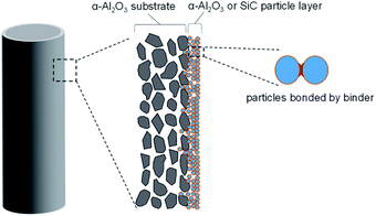 |
| | Fig. 1 The schematic structure of α-Al2O3 or SiC particle membranes. | |
2.4 Gas permeance of membranes and H2SO4 conversion
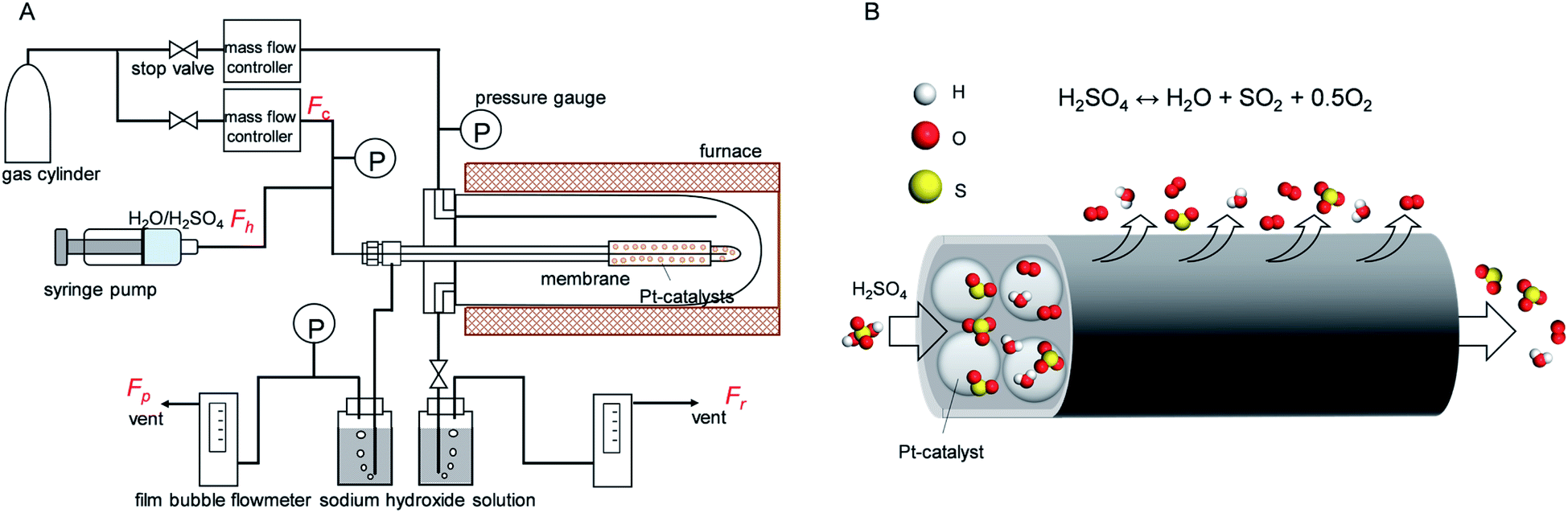
The gas permeation of membranes during H2SO4 and H2O exposure was tested in membrane module shown schematically in Fig. 2. Distilled H2O (0.48 ml h−1) or H2SO4 (1.0 ml h−1) was introduced into the membrane via a syringe pump, and helium was supplied as a carrier gas (flow rate of 90 ml min−1) to control the molar ratio of H2O or H2SO4 at 0.1 bar. Membranes of different types, M1–M5, were placed in an electric furnace with a controlled inner-side temperature of 600 °C for evaporation and reaction. Once H2SO4 was injected inside the heated zone, liquid H2SO4 was evaporated, and then thermally decomposed into sulfur trioxide and water vapor. After exposure tests for several hours, membranes were dried with N2 flow in the furnace at 600 °C, followed by cooling to room temperature. Then, the membrane module and gas lines were carefully cleaned by water to wash out the remaining H2SO4 and dried in an 80 °C oven. Pure gas permeance was measured under the transmembrane pressure difference from 0.01 to 1 bar by feeding gas to the outside of the membrane.
 |
| | Fig. 2 (A) Schematic diagram of the experiment for steam and sulphuric acid treatment and gas permeance measurement. (B) Schematic illustration of the SiC membrane used membrane reactor for H2SO4 decomposition. | |
An M4 membrane was used for the membrane reactor to An M4 membrane was used for the membrane reactor to investigate the effect of O2 extraction on H2SO4 decomposition conversion. At 600 °C, the liquid sulphuric acid changes to a gas phase, and the decomposition reaction can be split into two endothermic sub-reactions. The first sub-reaction is the dissociation of sulphuric acid into sulphur trioxide and water (reaction (3)), and the second is the decomposition of sulphur trioxide into sulphur dioxide and oxygen (reaction (4)). Here, SO3 was decomposed to SO2 with the Pt/Al2O3 catalyst (1.5 g, Shimadzu Corporation), which was packed inside the membrane. Outlet gases from the membrane reactor, consisting of mixtures of carrier gas He, and H2O, SO3, SO2, and O2, as produced from H2SO4 decomposition, subsequently passed through two bottles filled with 120 ml sodium hydroxide aqueous solution (20 wt%), where H2O was condensed and SO3 or SO2 was trapped by the neutralization reaction. So the outlet gas consisted of He and O2 and was measured using a soap film bubble flowmeter. NaOH was chosen for acidic gas absorption because it had high efficiency (nearly 100%) with SO2 removal.36 For safety, a SO2 alarm (ToxiRAE II, PGM-1130) was set nearby the equipment to signal SO2 leakage, and the outlet gas in the NaOH trap was monitored by the SO2 alarm and the SO2 content was found to be lower than 1 ppm.
H2SO4 conversion (w) can be quantified by the ratio of produced O2 over theoretical O2 since 1 mol of H2SO4 can produce 0.5 mol of O2 after complete conversion. Therefore, the conversion can be expressed in the following equation:
In that equation,
Fr and
Fp are the gas molar rate (mol s
−1) of retentate and permeate side of the membrane,
Fc is the molar rate of carried gas He.
Fh (mol s
−1) is the feed rate of liquid H
2SO
4. It is of note that H
2SO
4 was 100% decomposed to H
2O and SO
3 at 450 °C, hence, from this perspective, the H
2SO
4 conversion to SO
2 was dominated by SO
3 decomposition.
3. Results and discussion
3.1 Stability of membrane materials under H2SO4 exposure
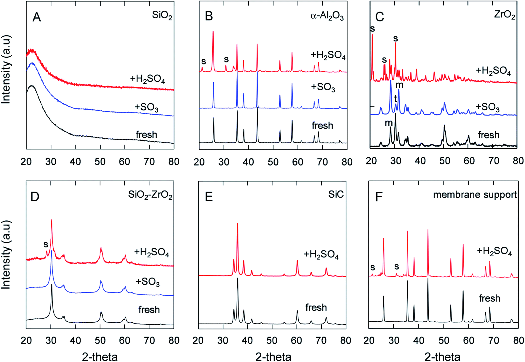
It has been pointed out that the α-Al2O3, SiO2 and lower-Zr-content SiO2–ZrO2 powders had good chemical stability against SO2 and SO3 even at 550 °C for O2/SO2 or O2/SO3 separation.5,37 The H2SO4 decomposition generates water vapor at temperatures higher than 300 °C, and, hence, the stability and corrosion under steam/acid still needs to be addressed. Therefore, Fig. 3 depicts the XRD patterns of the samples after being treated in SO3 or H2SO4 vapor at 600 °C for 24 h. The XRD patterns of SiO2 (Fig. 3A) showed a broad single peak centered at 23°, which was assigned to an amorphous SiO2 phase, and no other peaks were observed in the XRD patterns. Additionally, Nadar et al. also reported that TG-DTA and XRD patterns of SiO2 after H2SO4 exposure were similar to those before H2SO4,38 indicating the high acid resistance of SiO2. Table 2 shows the BET area of SiO2 powders was largely decreased after being treated in steam and in H2SO4 vapor. The reason for this decrease in the BET area could have centered around the reaction of Si–O–Si and H2O to form Si–OH, which could have led to large non-selective pores and resultant particles that became dense.34,39 XRD analyses of α-Al2O3 (Fig. 3B) powders revealed that the S in Al2(SO4)3 and the percentage of sulfur/aluminum detected by EDS had increased from 0.87 to 26%, as shown in Table 2. Also, the FT-IR spectra confirmed that an SO4 peak was formed in α-Al2O3 (ESI-2†), which was attributed to the reaction of alumina with the H2SO4 vapor at 600 °C. Furthermore, BET analyses revealed how the surface area of α-Al2O3 had decreased from 8.8 to 1.9 m2 g−1 following exposure to H2SO4, presumably due to the formation of Al2(SO4)3 on the surface, which reduced the size of the pores. Regarding the homemade Al2O3 powder, which had a high surface area of 226 m2 g−1 compared with that of crystalline α-Al2O3 at 8.8 m2 g−1, the BET area was drastically decreased after exposure to SO3 and H2SO4, but the reactivity was significantly greater under H2SO4 vapor than under SO3. Fig. 3C shows the XRD of ZrO2, which exhibited an increased crystalline monoclinic (m) ZrO2 from the tetragonal (t) phase40 due to the temperature swings of the membrane furnace and the dryer oven. XRD analysis did not detect the sulfate phase for ZrO2 and SiO2–ZrO2 (Si/Zr = 7/3) powders after SO3 exposure, as shown in Fig. 3C and D, and corresponded to low S ratios of 2.7 and 2.2%,5 respectively. On the contrary, after exposure to H2SO4 vapor at the same temperature of 600 °C, the S ratio was quite different between ZrO2 and SiO2–ZrO2 powders. The XRD spectra in Fig. 3C shows the formation of Zr(SO4)2 from ZrO2 after H2SO4 exposure, with only a small amount of crystalline Zr(SO4)2 (S peak)41 detected for SiO2–ZrO2 (Fig. 3D). In addition, Table 2 shows the S content measured by EDS was almost 100 and 4.0% for ZrO2 and SiO2–ZrO2 powders, respectively. Probable reasons for the high sulfur composition in ZrO2 powders after exposure to H2SO4 vapor could be primarily that H2O activated ZrO2 and formed ZrO(OH)2 or Zr(OH)4 at high temperature.42 Another explanation could be that either ZrO(OH)2 or Zr(OH)4 was more active in the reaction with SO3 to form Zr(SO4)2. Fig. 3E shows the XRD spectra of silicon-carbide powders before and after H2SO4 exposure. No change in peaks was observed, probably because SiC is generally known for its ultrahigh chemical and thermal stability.43–45 Additionally, the α-Al2O3 membrane supports used in this study were proven to be chemically stable under H2SO4, which was confirmed by XRD analysis to have a lesser amount of aluminum sulfate (Fig. 3F) compared with that of α-Al2O3 powders (Fig. 3B). This was probably because SiO2 was added to the Al2O3 membrane supports since Si was detected in the Al2O3 membrane supports, although the exact content was not available. Although the S content was 17% for α-Al2O3 membrane supports after H2SO4 exposure, the change in the element composition of the substrates had less of an effect on gas permeation (Fig. 5). To benefit the stability of these materials against H2SO4 in the IS process, the use of α-Al2O3 membrane supports, SiC and SiO2–ZrO2 were proposed for the preparation of SiC membranes.
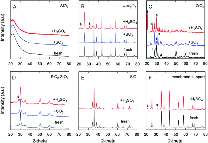 |
| | Fig. 3 XRD of different powders after SO3 or H2SO4 exposure at 600 °C under one-atmosphere pressure. S: zirconium sulfate or aluminum sulfate, t/m: tetragonal/monoclinic ZrO2. (A) Home-made SiO2. (B) α-Al2O3. (C) ZrO2. (D) SiO2–ZrO2 (Si/Zr = 7/3). (E) SiC. (F) α-Al2O3 membrane support. | |
Table 2 BET area and S ratio of powders after H2O or H2SO4 exposure
| Powders |
Air-fired T/°C |
BET area (m2 g−1) |
S/Al or S/(Si + Zr) mole ratio (%) |
| Fresh |
After H2O |
After H2SO4 |
| SiO2 |
600 |
650 |
600 |
390 |
<0.1 |
| Home-made Al2O3 |
600 |
226 |
18 |
6.4 |
86 |
| α-Al2O3 |
>1200 |
8.8 |
11 |
1.9 |
26 |
| Membrane support |
>1200 |
0.21 |
0.14 |
0.57 |
17 |
| SiO2–ZrO2 |
600 |
115 |
25 |
14.9 |
4.0 |
| ZrO2 |
600 |
21 |
20 |
3.2 |
100 |
| SiC |
>1800 |
10.0 |
10.5 |
9.0 |
<0.1 |
Fig. 4 features the SEM micrographs of SiO2, α-Al2O3 and ZrO2 before and after exposure to H2SO4. As shown in the images of Fig. 4A1 and A2, the surface of SiO2 powders were smooth after H2SO4 exposure, which demonstrated morphological differences between the fresh state and after SO3 exposure5 while maintaining approximately the same particle size. This could be explained by the densification of SiO2 fine particles induced by the reaction between Si–O–Si and H2O. Fig. 4B1 and B2 shows that α-Al2O3 particles had a relatively uniform morphology even after H2SO4 exposure while the size of the Al2O3 particles grew larger due to the formation of low-melting Al2(SO4)3 on the surface, with which each of the primary particles seemed to be connected and aggregated that differed from the α-Al2O3 particles with SO3 exposure.5 Given that α-Al2O3 particles after exposure were deposited with, and covered by, the Al2(SO4)3, these SEM photos confirm the compositions obtained by EDS. The SEM images in Fig. 4C1 and C2 also show that the fine ZrO2 particles had reacted with the H2SO4 vapor and increased in size, which is similar to the growth of α-Al2O3 powder under H2SO4 exposure, probably due to the effect of dissolution under the H2O vapor and to the reaction with SO3.
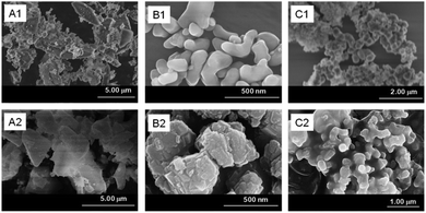 |
| | Fig. 4 SEM of fresh SiO2 (A1), α-Al2O3 (B1), ZrO2 (C1) powders. (A2), (B2) and (C2) were those powders after H2SO4 (100 kPa) exposure at 600 °C, respectively. | |
3.2 Permeance of the SiC membrane reactor for H2SO4 decomposition
Porous inorganic membranes were first explored under an extreme condition, i.e., H2SO4 decomposition at 600 °C. Fig. 5 shows the time course of the N2 permeance with increases in the treatment time under H2SO4 vapor. The N2 permeance of the α-Al2O3 membrane support (M1) was decreased only slightly even after 22 h of exposure to H2SO4 vapor at 600 °C, since the membrane support provided only moderate chemical stability, as shown in Fig. 3F (XRD) and Table 2, and the large pores changed very little even after sulfate formation. M2, M3, and M4 prepared with different particles (SiC, α-Al2O3) and binders (SiO2–ZrO2, SiO2) showed N2 permeance at the same level (10−5 mol m−2 s−1 Pa−1) as before the stability test, which provided a fair comparison and verified good reproducibility of the membrane fabrication. Values were drastically decreased for the permeance of both M2 and M3 Al2O3 particle layers following H2SO4 exposure for 4 h. The permeance of M2 was further decreased, however, confirming that the high Zr content in the binder (Si/Zr = 5/5) was more unstable due to the formation of Zr(SO4)2 with H2SO4, similar to high Zr content SiO2–ZrO2 (Si/Zr = 5/5) in SO3.5 These results were reasonable, and strongly suggested that the membranes should be prepared using Si-rich SiO2–ZrO2 (Si/Zr = 7/3) as a binder. M4 and M5 SiC particle layers showed a very small decrease and high relative permeance over all the particle membranes, M2–M5. That indicated that the membrane prepared by SiC with Si-rich SiO2–ZrO2 (Si/Zr = 7/3) increased both the chemical and hydrothermal stability compared with that of the Al2O3 particle layers with Zr-rich SiO2–ZrO2 used to fabricate M2 and M3. The morphology changed less for membranes fabricated with SiC layers following exposure to H2SO4 (ESI-3†), which corresponds to the stability confirmed by XRD and BET results. These results suggested that the SiC was stable for fabricating a particle layer for membrane preparation in the IS process.
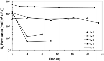 |
| | Fig. 5 Time course of N2 permeance for α-Al2O3 membrane support (M1) and membrane prepared by Al2O3 particle layer (M2, M3), and SiC particle (M4, M5) after the treatment under H2SO4 vapor at 600 °C. | |
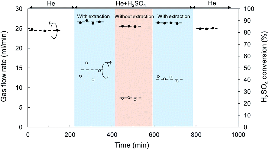
Catalytic membrane reactor for H2SO4 decomposition, liquid H2SO4 (98%) was fed at a flow rate of 1.0 ml h−1 and He was used as the carrier gas with a flow rate of 24.5 ml min−1 controlled by a mass flow controller. Fig. 6 shows the time course for the total flow rate of the outlet gas in both the retentate and permeate, and the conversion of H2SO4 decomposition at 600 °C in a SiC particle-derived membrane reactor. A brief flow sheet with or without extraction is shown in ESI-4.† The membrane reactor with extraction, O2 with low molecular weight was transferred faster than SO2 and SO3, and SO3, and the largest molecular weight, permeated at the slowest speed by Knudsen diffusion through the mesoporous SiC membrane.46 Therefore, the equilibrium of the reaction (R4) (SO3 ↔ SO2 + 0.5O2) was forwarded to the product side by removing O2. In a comparison with a membrane without extraction, the membrane reactor with extraction achieved higher conversion at the same temperature of 600 °C. The catalytic membrane reactor obtained conversion of 25% without extraction, which approximated the equilibrium (theoretical) conversion of SO3 decomposition (eqn (4)) of 28% at 900 K.3 Comparison with membrane without extraction, the conversion of H2SO4 decomposition was increased to 45%, which was much higher at the same temperature of 600 °C. Additionally, the H2SO4 decomposition conversion remained constant at around 41% after membrane exposure to H2SO4 vapor for 10 h. Moreover, after decomposition for 10 h, He permeance was approximately the same as that before the decomposition reaction, which indicated that the SiC particle layer (with SiO2–ZrO2) had high hydrothermal and chemical stability under H2O and SO3. However, the separation properties of M4 membranes was still poor; the He/N2 permeance ratio was 2.3 with N2 permeance of 4.5 × 10⁻⁵ mol m−2 s−1 Pa−1, since the SiC membrane was fabricated using SiC particles, and the gaps between particles were large enough to allow gas to pass through.
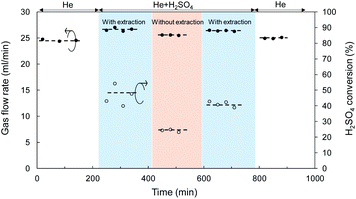 |
| | Fig. 6 Time course of gas flow rate and H2SO4 conversion for a SiC membrane tested in the catalytic membrane reactor at 600 °C. | |
4. Conclusions
SiC mesoporous membranes were successfully prepared using an α-Al2O3 support and a SiC particle layer. The gas permeance of the SiC membrane was stable for 20 h under H2SO4 vapor at 600 °C, which indicated its high chemical stability. Regarding the H2SO4 decomposition reaction, the SiC membrane achieved a conversion of 41% at 600 °C, which was much higher than that of the membrane without extraction (25%). Our previous work involved the preliminary use of SiC membranes in a catalytic membrane reactor for hydrogen production in the iodine–sulfur process, and a desirable design for a SiC subnanoporous membrane with a combination of high O2 permeance and O2/SO2 selectivity will be a major objective in the future.
Conflicts of interest
There are no conflicts to declare.
Acknowledgements
This work was supported by the Cross-ministerial Strategic Innovation Promotion Program (SIP) of the Energy Carrier Project of the Japan Science and Technology Agency (JST) and the Japan Society for the Promotion of Science (JSPS) KAKENHI Grant Number JP20H052279.
Notes and references
- S. Kasahara, G.-J. Hwang, H. Nakajima, H.-S. Choi, K. Onuki and M. Nomura, Effects of process parameters of the IS process on total thermal efficiency to produce hydrogen from water, J. Chem. Eng. Jpn., 2003, 36, 887–899 CrossRef CAS.
- D. M. Ginosar, H. W. Rollins, L. M. Petkovic, K. C. Burch and M. J. Rush, High-temperature sulfuric acid decomposition over complex metal oxide catalysts, Int. J. Hydrogen Energy, 2009, 34, 4065–4073 CrossRef CAS.
- L. Meng, M. Kanezashi and T. Tsuru, Catalytic membrane reactors for SO3 decomposition in iodine–sulfur thermochemical cycle: a simulation study, Int. J. Hydrogen Energy, 2015, 40, 12687–12696 CrossRef CAS.
- O. Myagmarjav, A. Ikeda, N. Tanaka, S. Kubo and M. Nomura, Preparation of an H2-permselective silica membrane for the separation of H2 from the hydrogen iodide decomposition reaction in the iodine–sulfur process, Int. J. Hydrogen Energy, 2017, 42, 6012–6023 CrossRef CAS.
- X. Yu, L. Meng, H. Nagasawa, M. Kanezashi, M. Machida and T. Tsuru, Evaluating the chemical stability of metal oxides in SO3 and applications of SiO2-based membranes to O2/SO3 separation, J. Am. Ceram. Soc., 2019, 102, 6946–6956 CrossRef CAS.
- A. Nadar, A. M. Banerjee, M. Pai, S. S. Meena, R. Pai, R. Tewari, S. Yusuf, A. Tripathi and S. Bharadwaj, Nanostructured Fe2O3 dispersed on SiO2 as catalyst for high temperature sulfuric acid decomposition—structural and morphological modifications on catalytic use and relevance of Fe2O3-SiO2 interactions, Appl. Catal., B, 2017, 217, 154–168 CrossRef CAS.
- M. Nomura, Application of an electrochemical membrane reactor to the thermochemical water splitting IS process for hydrogen production, J. Membr. Sci., 2004, 240, 221–226 CrossRef CAS.
- X. Liu, B. Jiang, X. Yin, H. Ma and B. S. Hsiao, Highly permeable nanofibrous composite microfiltration membranes for removal of nanoparticles and heavy metal ions, Sep. Purif. Technol., 2020, 233, 115976 CrossRef CAS.
- P. H. Duong, V. A. Kuehl, B. Mastorovich, J. O. Hoberg, B. A. Parkinson and K. D. Li-Oakey, Carboxyl-functionalized covalent organic framework as a two-dimensional nanofiller for mixed-matrix ultrafiltration membranes, J. Membr. Sci., 2019, 574, 338–348 CrossRef CAS.
- S. Anisah, W. Puthai, M. Kanezashi, H. Nagasawa and T. Tsuru, Preparation, characterization, and evaluation of TiO2-ZrO2 nanofiltration membranes fired at different temperatures, J. Membr. Sci., 2018, 564, 691–699 CrossRef CAS.
- G. Dong, H. Nagasawa, L. Yu, M. Guo, M. Kanezashi, T. Yoshioka and T. Tsuru, Energy-efficient separation of organic liquids using organosilica membranes via a reverse osmosis route, J. Membr. Sci., 2020, 597, 117758 CrossRef CAS.
- Y. Ying, M. Tong, S. Ning, S. K. Ravi, S. B. Peh, S. C. Tan, S. J. Pennycook and D. Zhao, Ultrathin Two-Dimensional Membranes Assembled by Ionic Covalent Organic Nanosheets with Reduced Apertures for Gas Separation, J. Am. Chem. Soc., 2020, 142, 4472–4480 CrossRef CAS.
- C. Z. Liang, T.-S. Chung and J.-Y. Lai, A review of polymeric composite membranes for gas separation and energy production, Prog. Polym. Sci., 2019, 97, 101141 CrossRef CAS.
- L. Yu, M. Kanezashi, H. Nagasawa, N. Moriyama, T. Tsuru and K. Ito, Enhanced CO2 separation performance for tertiary amine-silica membranes via thermally induced local liberation of CH3Cl, AIChE J., 2018, 64, 1528–1539 CrossRef CAS.
- X. Ren, M. Kanezashi, H. Nagasawa and T. Tsuru, Plasma-assisted multi-layered coating towards improved gas permeation properties for organosilica membranes, RSC Adv., 2015, 5, 59837–59844 RSC.
- G. Gong, H. Nagasawa, M. Kanezashi and T. Tsuru, Reverse osmosis performance of layered-hybrid membranes consisting of an organosilica separation layer on polymer supports, J. Membr. Sci., 2015, 494, 104–112 CrossRef CAS.
- T. Tsuru, Silica-Based Membranes with Molecular-Net-Sieving Properties: Development and Applications, J. Chem. Eng. Jpn., 2018, 51, 713–725 CrossRef CAS.
- M. Elimelech and W. A. Phillip, The future of seawater desalination: energy, technology, and the environment, Science, 2011, 333, 712–717 CrossRef CAS.
- M. Nomura, T. Kodaira, A. Ikeda, Y. Naka, H. Nishijima, S.-i. Imabayashi, S.-i. Sawada, T. Yamaki, N. Tanaka and S. Kubo, Development of ion-exchange membranes for the membrane bunsen reaction in thermochemical hydrogen production by iodine-sulfur process, J. Chem. Eng. Jpn., 2018, 51, 726–731 CrossRef.
- O. Myagmarjav, J. Iwatsuki, N. Tanaka, H. Noguchi, Y. Kamiji, I. Ioka, S. Kubo, M. Nomura, T. Yamaki and S. Sawada, Research and development on membrane IS process for hydrogen production using solar heat, Int. J. Hydrogen Energy, 2019, 44, 19141–19152 CrossRef CAS.
- O. Myagmarjav, N. Tanaka, M. Nomura and S. Kubo, Module design of silica membrane reactor for hydrogen production via thermochemical IS process, Int. J. Hydrogen Energy, 2019, 44, 10207–10217 CrossRef CAS.
- N. Tanaka, H. Noguchi, Y. Kamiji, H. Takegami and S. Kubo, Hydriodic iodide and iodine permeation characteristics of fluoropolymers as a lining material, Int. J. Hydrogen Energy, 2020, 45, 17557–17561 CrossRef CAS.
- B. Bhushan, N. Goswami, S. Parida, B. Rath, S. A. Kumar, V. Karki, R. Bindal and S. Kar, Corrosion behavior analyses of metallic membranes in hydrogen iodide environment for iodine-sulfur thermochemical cycle of hydrogen production, Int. J. Hydrogen Energy, 2018, 43, 10869–10877 CrossRef CAS.
- B. Huang, Y. Zhu, Y. He, S. Xu, Y. Zhang and Z. Wang, Influence of catalyst coated membranes on electrochemical bunsen reaction in the sulfur-iodine cycle, Int. J. Hydrogen Energy, 2019, 44, 9735–9742 CrossRef CAS.
- C. Forsberg, L. Trowbridge, B. Bischoff and L. K. Mansur, Sulfur thermochemical processes with inorganic membranes to produce hydrogen, Citeseer, AIChE Spring National Meeting New Orleans, Louisiana, USA, 2004 Search PubMed.
- G. He, R. H. Elder, D. C. Sinclair and R. W. K. Allen, High temperature oxygen separation for the sulphur family of thermochemical cycles – Part II: sulphur poisoning and membrane performance recovery, Int. J. Hydrogen Energy, 2013, 38, 785–794 CrossRef CAS.
- O. Myagmarjav, N. Tanaka, M. Nomura and S. Kubo, Comparison of experimental and simulation results on catalytic HI decomposition in a silica-based ceramic membrane reactor, Int. J. Hydrogen Energy, 2019, 44, 30832–30839 CrossRef CAS.
- L. Meng, M. Kanezashi, X. Yu and T. Tsuru, Enhanced decomposition of sulfur trioxide in the water-splitting iodine–sulfur process via a catalytic membrane reactor, J. Mater. Chem. A, 2016, 4, 15316–15319 RSC.
- M. Elma, C. Yacou, J. C. Diniz da Costa and D. K. Wang, Performance and long term stability of mesoporous silica membranes for desalination, Membranes, 2013, 3, 136–150 CrossRef CAS.
- G. Caputo, C. Felici, P. Tarquini, A. Giaconia and S. Sau, Membrane distillation of HI/H2OHI/H2O and H2SO4/H2OH2SO4/H2O mixtures for the sulfur–iodine thermochemical process, Int. J. Hydrogen Energy, 2007, 32, 4736–4743 CrossRef CAS.
- H. Schoeman, H. M. Krieg, A. J. Kruger, A. Chromik, K. Krajinovic and J. Kerres, H2SO4 stability of PBI-blend membranes for SO2 electrolysis, Int. J. Hydrogen Energy, 2012, 37, 603–614 CrossRef CAS.
- M. Kanezashi, K. Yada, T. Yoshioka and T. Tsuru, Design of silica networks for development of highly permeable hydrogen separation membranes with hydrothermal stability, J. Am. Chem. Soc., 2009, 131, 414–415 CrossRef CAS.
- X. Yu, H. Nagasawa, M. Kanezashi and T. Tsuru, Improved thermal and oxidation stability of bis(triethoxysilyl)ethane (BTESE)-derived membranes, and their gas-permeation properties, J. Mater. Chem. A, 2018, 6, 23378–23387 RSC.
- H. L. Castricum, A. Sah, R. Kreiter, D. H. A. Blank, J. F. Vente and J. E. Ten Elshof, Hydrothermally stable molecular separation membranes from organically linked silica, J. Mater. Chem., 2008, 18, 2150–2158 RSC.
- W. Puthai, M. Kanezashi, H. Nagasawa, K. Wakamura, H. Ohnishi and T. Tsuru, Effect of firing temperature on the water permeability of SiO2–ZrO2 membranes for nanofiltration, J. Membr. Sci., 2016, 497, 348–356 CrossRef CAS.
- J. Zhang, R. Zhang, X. Chen, M. Tong, W. Kang, S. Guo, Y. Zhou and J. Lu, Simultaneous Removal of NO and SO2 from Flue Gas by Ozone Oxidation and NaOH Absorption, Ind. Eng. Chem. Res., 2014, 53, 6450–6456 CrossRef CAS.
- L. Meng, M. Kanezashi, J. Wang and T. Tsuru, Permeation properties of BTESE–TEOS organosilica membranes and application to O2/SO2 gas separation, J. Membr. Sci., 2015, 496, 211–218 CrossRef CAS.
- A. Nadar, A. M. Banerjee, M. Pai, R. Pai, S. S. Meena, R. Tewari and A. Tripathi, Catalytic properties of dispersed iron oxides Fe2O3/MO2 (M= Zr, Ce, Ti and Si) for sulfuric acid decomposition reaction: role of support, Int. J. Hydrogen Energy, 2018, 43, 37–52 CrossRef CAS.
- M. Landau, S. Varkey, M. Herskowitz, O. Regev, S. Pevzner, T. Sen and Z. Luz, Wetting stability of Si-MCM-41 mesoporous material in neutral, acidic and basic aqueous solutions, Microporous Mesoporous Mater., 1999, 33, 149–163 CrossRef CAS.
- H. Nayebzadeh, N. Saghatoleslami and M. Tabasizadeh, Application of microwave irradiation for fabrication of sulfated ZrO2–Al2O3 nanocomposite via combustion method for esterification reaction: process condition evaluation, J. Nanostruct. Chem., 2019, 9, 141–152 CrossRef CAS.
- M. Testa, V. La Parola, F. Mesrar, F. Ouanji, M. Kacimi, M. Ziyad and L. Liotta, Use of Zirconium Phosphate-Sulphate as Acid Catalyst for Synthesis of Glycerol-Based Fuel Additives, Catalysts, 2019, 9, 148 CrossRef.
- P. Graf, D. De Vlieger, B. Mojet and L. Lefferts, New insights in reactivity of hydroxyl groups in water gas shift reaction on Pt/ZrO2, J. Catal., 2009, 262, 181–187 CrossRef CAS.
- T. Ishikawa, Y. Kohtoku, K. Kumagawa, T. Yamamura and T. Nagasawa, High-strength alkali-resistant sintered SiC fibre stable to 2,200 °C, Nature, 1998, 391, 773–775 CrossRef CAS.
- S. Tomar, S. Gangwar, K. Kondamudi and S. Upadhyayula, SO3 decomposition over β-SiC and SiO2 supported CuFe2O4: a stability and kinetic study, Int. J. Hydrogen Energy, 2020, 45, 21287–21296 CrossRef CAS.
- H. A. Khan, P. Natarajan and K.-D. Jung, Stabilization of Pt at the inner wall of hollow spherical SiO2 generated from Pt/hollow spherical SiC for sulfuric acid decomposition, Appl. Catal., B, 2018, 231, 151–160 CrossRef CAS.
- T. Yoshioka, M. Kanezashi and T. Tsuru, Micropore size estimation on gas separation membranes: a study in experimental and molecular dynamics, AIChE J., 2013, 59, 2179–2194 CrossRef CAS.
Footnote |
| † Electronic supplementary information (ESI) available. See DOI: 10.1039/d0ra06919a |
|
| This journal is © The Royal Society of Chemistry 2020 |
Click here to see how this site uses Cookies. View our privacy policy here. 
 Open Access Article
 This Open Access Article is licensed under a Creative Commons Attribution-Non Commercial 3.0 Unported Licence
 ,
Qing Wang
,
Qing Wang