DOI:
10.1039/D0RA06866G
(Paper)
RSC Adv., 2020,
10, 44997-45007
Synthesis and characterization of an α-Fe2O3/ZnTe heterostructure for photocatalytic degradation of Congo red, methyl orange and methylene blue
Received
9th August 2020
, Accepted 16th November 2020
First published on 21st December 2020
Abstract
The leading challenge towards environmental protection is untreated textile dyes. Tailoring photocatalytic materials is one of the sustainable remediation strategies for dye treatment. Hematite (α-Fe2O3), due to its favorable visible light active band gap (i.e. 2.1 eV), has turned out to be a robust material of interest. However, impoverished photocatalytic efficiency of α-Fe2O3 is ascribable to the short life span of the charge carriers. Consequently, the former synthesized heterostructures possess low degradation efficiency. The aim of the proposed endeavor is the synthesis of a novel zinc telluride-modified hematite (α-Fe2O3/ZnTe) heterostructure, its characterization and demonstration of its enhanced photocatalytic response. The promising heterostructure as well as bare photocatalysts were synthesized via a hydrothermal approach. All photocatalysts were characterized by the X-ray diffraction technique (XRD), scanning electron microscopy (SEM), and electron diffraction spectroscopy (EDX). Moreover, the selectivity and activity of the photocatalyst are closely related to the alignment of its band energy levels, which were estimated by UV-Vis diffuse reflectance spectroscopy (DRS) and X-ray photoelectron spectroscopy (XPS). Nanomaterials, specifically α-Fe2O3 and α-Fe2O3/ZnTe, were used for the degradation of Congo red (97.9%), methyl orange (84%) and methylene blue (73%) under light irradiation (>200 nm) for 60 min. The results suggested that with the aforementioned optimized fabricated heterostructure, the degradation efficiency was improved in comparison to bare hematite (α-Fe2O3). The key rationale towards such improved photocatalytic response is the establishment of a type-II configuration in the α-Fe2O3/ZnTe heterostructure.
1 Introduction
Textile dyeing wastewater is a major contributor to water pollution and it is troublesome due to the presence of highly stable carcinogenic compounds, such as azo dyes, which are resistant to biodegradation.1 Consequently, it needs to be effectively treated on a priority basis. A great number of separation techniques have been utilized so far to remove dyestuffs, including physical methods (adsorption,2,3 flocculation, coagulation,4 and membrane filtration),5 biological methods (aerobic and anaerobic treatment) and chemical methods (ozonation, photo-Fenton reaction and photocatalysis).6 In these methods, physical and biological methods encounter some drawbacks as both techniques are non-destructive, uneconomical and also generate secondary pollutants, while heterogeneous photocatalysis is preferable to achieve complete mineralization of toxic and non-biodegradable species into non-toxic species.7
Many photocatalysts, including ZnO,8–10 TiO2,11 ZnSe,12,13 and binary (ZrO2, CeO2, Ga2O3, NiO, Nb2O5, Ta2O5, Bi2O3, V2O5, WO3, Cu2O) and ternary (Bi2WO6, BiMoO6, vanadates) compounds,7 have been applied to degrade dyes in wastewater treatment. However, using such semiconductor materials is restricted by the short life span of the photogenerated charge carriers or large band gap, which causes low solar energy utilization.14 Therefore, designing new materials is necessary for real-time control of dyeing wastewater. Hematite (α-Fe2O3), with a band gap of 2.1 eV, has been emerging as a promising candidate in wastewater treatment due to its versatile characteristics, like visible light absorption, easy fabrication, earth abundance, high thermal stability and excellent photocatalytic properties.15–20 Unfortunately, owing to the short life span of the light-generated charge carriers (i.e. <10 ps), its photocatalytic activity is significantly limited.21 In order to enhance its photocatalytic activity, different techniques have been employed so far, e.g. metal and non-metal doping.22 However, doping increases the risk of introducing defects into the crystal structure, which could act as recombination centers, facilitating photogenerated charge carrier recombination.23 To prevent this, the combination of α-Fe2O3 with other semiconductors would give enhanced photocatalytic performance as compared to the single photocatalyst due to spatial separation of charge carriers.24–27 To date, different composites of hematite have been reported for degradation purposes. The results indicated that a maximum of 67% of phenol was degraded when α-Fe2O3/rGO was introduced for phenol degradation.23 α-Fe2O3/g-C3N4 achieved 90% photodegradation of Rhodamine B (RhB) within 90 min.24 A heterostructure of carbon dots with hematite was utilized for the degradation of indigo carmine dye.25 SnO2/α-Fe2O3 was used for the decolorization of methylene blue (MB), and 84% MB was degraded by this fabricated photocatalyst.26 α-Fe2O3/ZnO was employed for the degradation of RhB and the degradation reached approximately 92%.27 Also, ZnTe was considered as an attractive material for designing novel photocatalysts due to its various applications, like photoconversion of carbon dioxide to methane.28,29 With respect to reported content, a ZnTe-modified α-Fe2O3 nanocomposite has not been reported so far for dye degradation.
In this paper, the synthesis of a novel and promising photocatalyst, viz. a ZnTe-modified α-Fe2O3 nanocomposite, and its characterization via XRD, SEM, EDX, DRS and XPS are achieved. Moreover, the activity of the designed photocatalyst is investigated by degradation of Congo red (CR), methyl orange (MO) and methylene blue (MB). The degradation results suggest that the ZnTe-modified α-Fe2O3 nanocomposite, as an efficient photocatalytic system, can effectively decrease the dye content from wastewater via photodegradation.
2 Materials & methods
2.1. Materials
The chemicals utilized for the synthesis of the photocatalysts were of analytical grade and used without further treatment. All of the solutions were prepared in DI-water. Congo red [C32H24N6O6S2·2Na] (M.W. = 696.67 g mol−1), ferric nitrate nonahydrate [Fe(NO3)3·9H2O] (M.W. = 403.99 g mol−1, >97%), urea [NH2CONH2] (M.W. = 60.07 g mol−1, 99.5%) and potassium hydroxide [KOH] (M.W. = 56.11 g mol−1, >95%) were purchased from Merck. Zinc powder (M.W. = 65.38 g mol−1, >97%) and tellurium powder (M.W. = 127.38 g mol−1, 99.8%) were purchased from Sigma Aldrich Chemicals. Meanwhile, methyl orange [C14H14N3NaO3S] (M.W. = 327.33 g mol−1) and methylene blue [C16H18N3SCl] (M.W. = 319.85 g mol−1) were supplied by Beijing Chemical Reagent Limited Corporation in China.
2.2. Synthesis
All of the nanoparticles in this study were synthesized by a high pressure hydrothermal method. To prepare the hematite (α-Fe2O3) nanoparticles, a homogeneous solution (0.1 M ferric nitrate and 0.15 M urea solutions) was prepared by adding urea drop wise to ferric nitrate under continuous stirring. Then the homogeneous mixture was transferred to a 40 mL Teflon tube that was filled to 80% of its capacity. The Teflon tube was then sealed in a stainless steel autoclave and was then placed in an oven for 4 hours at 200 °C. Afterwards, the resulting red colored precipitates were centrifuged, and washed three times (two times with DI-water and finally with ethanol) to washout any impurities. The sample was then dried overnight in a vacuum oven at 70 °C. The dried powders were ground in an agate mortar and pestle and stored for further use.
The possible formation mechanism of the nanoparticles would involve a series of chemical reactions (Fig. 1). Firstly, the dissolved urea decomposes to carbon dioxide and ammonia upon heating (eqn (1)).
 |
| | Fig. 1 Pictorial illustration of the possible formation mechanism of hematite NPs. | |
The synthesis route using urea facilitates the precipitation strategy as compared to the adsorption route. Hydrolysis of ammonia yields ammonium ions (NH4+) and hydroxyl ions (OH−) is shown in eqn (2). Hydroxyl ions may react with ferric ions to generate Fe(OH)3, which is the primary growth unit with an amorphous structure.30 Neighboring primary nuclei grow further to form the hematite NPs (eqn (3)).
| | |
CH4N2O + H2O → CO2 + 2NH3
| (1) |
| | |
NH3 + H2O → NH4+ + OH−
| (2) |
| | |
Fe3+ + OH− → Fe(OH)3 → α-Fe2O3 (nanoparticle)
| (3) |
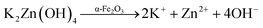
For the synthesis of ZnTe, potassium hydroxide (KOH) and zinc/tellurium powders were used as starting materials. The synthesis procedure involved the dissolution of 6.72 g of KOH in 32 mL of distilled water followed by the addition of 0.65 g of zinc powder and 0.63 g of tellurium powder. The resultant mixture was then transferred into a Teflon tube, which was then sealed in a stainless steel autoclave. The autoclave was kept in a heating oven at 120 °C for 2 h. The autoclave was then cooled to room temperature and the black powders were washed several times with deionized water and finally with ethanol, followed by vacuum drying overnight at 70 °C. The dried ZnTe was ground and stored for further characterization.
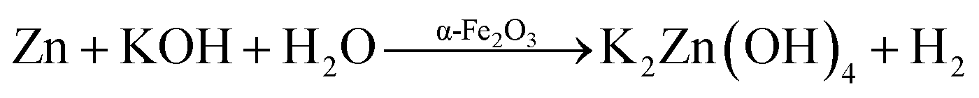
Each step towards the synthesis of ZnTe can be well elaborated by the following chemical equations. The reaction steps involved during the synthesis of ZnTe have been proposed. First, the zinc powder chemically interacts with KOH at high temperature and pressure to form potassium zincate with the liberation of hydrogen gas (eqn (4)).
| | |
Zn + KOH + H2O → K2Zn(OH)4 + H2
| (4) |
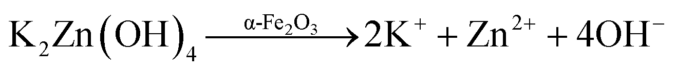
This zincate is then dissociated into the constituent ions, which are mobilized in the reaction system (eqn (5)).
| | |
K2Zn(OH)4 → 2K+ + Zn2+ + 4OH−
| (5) |
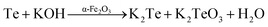
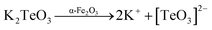
In addition, the respective tellurium powders, at elevated reaction conditions, react with KOH to give the respective potassium tellurites, which are water soluble and thus are dissociated into the anion species of their respective oxides (eqn (6) and (7)).
| | |
Te + KOH → K2Te + K2TeO3 + H2O
| (6) |
| | |
K2TeO3 → 2K+ + [TeO3]2−
| (7) |
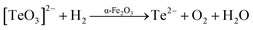
The oxide is further reduced to give Te2− (eqn (8)). Finally, these anions react together with Zn2+ to give the final ZnTe catalysts (eqn (9)).
| | |
[TeO3]2− + H2 → Te2− + O2 + H2O
| (8) |
| | |
Zn2+ + Te2− → ZnTe (nanoparticle)
| (9) |
The synthesis procedure of the α-Fe2O3/ZnTe photocatalyst is as follows. Initially 0.2 g of α-Fe2O3 is dispersed in 32 mL of distilled water under constant stirring and 0.65 g of Zn powder and 0.63 g of Te powder were then added into this mixture. The obtained solution was kept under continuous stirring for half an hour. Afterwards, 6.72 g of KOH was added into the above mixture, which was also placed for half an hour under continuous stirring. The mixture was finally transferred to a 40 mL Teflon tube, which was sealed in a stainless steel jacket (autoclave). The autoclave was then placed in an oven at 120 °C for 2 h. Afterwards, the as synthesized sample was washed several times with DI-water and finally with ethanol, dried in a vacuum oven at 70 °C for 8 h and ground with an agate mortar and pestle to obtain the finely divided powder. The synthesis mechanism for the formation of ZnTe-modified α-Fe2O3 is shown in eqn (10)–(15):
| |
 | (10) |
| |
 | (11) |
| |
 | (12) |
| |
 | (13) |
| |
 | (14) |
| |
 | (15) |
2.3. Photocatalyst characterization
XRD analysis was carried out using a Bruker D8 focus diffractometer with Ni-filtered Cu-Kα radiation to study the crystal structure and crystallinity of the prepared materials. The diffractograms were collected in the 2θ range of 20–80° at a scan rate of 0.1° min−1. The avg. crystallite size (D) was calculated with the Scherrer formula (eqn (16)).28| |
D = Kλ/β![[thin space (1/6-em)]](https://www.rsc.org/images/entities/char_2009.gif) cosθ cosθ
| (16) |
where D is crystallite size, K is shape constant, i.e. 0.89, λ is wavelength of X-ray radiation, β is full width at half maxim, and θ is diffraction angle. To investigate the optical properties of the synthesized photocatalysts, UV-Vis spectra as a function of wavelength were recorded between 300–800 nm using a Lambda 750 UV/Vis diffuse reflectance spectrophotometer with Indium as the reference standard. The Kubelka–Munk equation (eqn (17)) was utilized to calculate the band gap energy (Eg in eV).31where h is Plank's constant, ν is the frequency of vibration, α is the absorption coefficient, Eg is the band gap (eV), K is the proportional constant, and n is a constant. The value of n is determined from the nature of optical transition. n = 2 is direct allowed transition and n = 1/2 is indirect allowed transition. The optical band gap of a semiconductor can be estimated from the intercept of the extrapolated linear fit for the plotted experimental data of (αhν)n versus incident photon energy (hν) near the absorption edge. For α-Fe2O3 and ZnTe, both direct and indirect band gaps have been reported so far.32,33 However, in our case, the nature of the optical transition is a direct allowed transition. Therefore, (αhν)2 was used to calculate the band gap in Fig. 5b and d. Morphological as well as purity and elemental analyses of the synthesized photocatalysts were carried out using Hitachi S4800 scanning electron microscopy (SEM) and energy dispersive X-ray (EDX) spectroscopy, respectively. In addition, the valence band position and oxidation states of the photocatalysts were investigated via X-ray photoelectron spectroscopy (XPS) with an ESCALAB 250Xi X-ray photoelectron spectrophotometer with Al Kα radiation (hν = 1486.6 eV) operating at 150 W.
2.4. Photocatalyst activity measurements
The photocatalytic activity of the as synthesized photocatalysts against all dye degradation was investigated in an open Pyrex vessel of 50 mL capacity under a UV-Vis solar illumination source. The sample was placed perpendicular to the light source. After the adding up of the catalyst, the suspension was stirred in the dark for 30 min in order to reach absorption equilibrium. Then, the mixed solution was exposed to light. In order to maintain homogeneity during the course of the reaction, the suspension was agitated by a magnetic stirrer continuously. In this study, the dye concentration was measured by using a Lambda 750 UV/Vis diffuse reflectance spectrophotometer at wavelength (λmax) 499 nm, 464 nm and 668 nm for CR, MO and MB, respectively. In brief, a known amount of the three mentioned dyes (0.01 g) was added to distilled water to create dye solutions of different concentrations. In order to determine the maximum wavelength absorbency of the CR, MB and MO solutions, a UV/Vis spectrometer were used for calibration. A linear calibration curve was obtained with different concentrations of dye solution. To get the equation for the line, two points on the line were chosen to get the slope, and then the y-intercept c = y − mx was found; therefore, the equation for the line is y = mx + c. The equation can then be rearranged to make x (unknown concentration) the subject of the equation, and the values for m, c and y can be substituted in. Unambiguously, you can plug in the value for the absorbance of your unknown sample and calculate its concentration. For the photocatalytic test, 0.01 g of catalyst powder was dispersed in dye solution of 100 ppm. During irradiation, 3 mL of the suspension solution was collected at regular time intervals and instantly centrifuged (4000 rpm for 8 min) to separate the catalyst particles.
3 Results
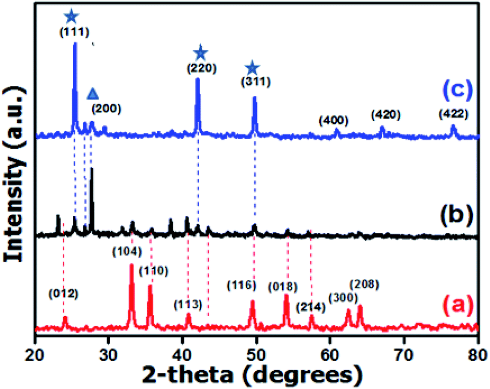
For verification of the purity, crystal structure, crystallinity and crystallite size, the as synthesized photocatalysts were investigated by the XRD technique in the 2θ range of 20 to 80° (see Fig. 2). All the crystalline parameters including the crystal system, calculated density and average crystallite size are summarized in Table 1.
 |
| | Fig. 2 XRD patterns of (a) α-Fe2O3, (b) α-Fe2O3/ZnTe and (c) ZnTe. | |
Table 1 Crystalline parameters derived from the XRD patterns for α-Fe2O3 and ZnTe
| Sr.# |
Photocatalysts |
Crystal system |
Avg. crystallite size (nm) |
Calculated density (g cm−3) |
| 1 |
α-Fe2O3 |
Rhombohedral |
32.5 |
5.25 |
| 2 |
ZnTe |
Cubic |
40.4 |
5.64 |
Energy dispersive X-ray spectroscopy was utilized to reveal the precise distribution of elements and the purity of the synthesized materials. The EDX spectrum as shown in Fig. 3a, illustrates the purity of hematite as only Fe and O are present (O: 60.36%; Fe: 39.64%). Fig. 3c is the EDX spectrum of the bare ZnTe. All of the peaks in the spectrum correspond to tellurium and zinc, depicting that the synthesized sample is impurity free. The elemental composition is zinc and telluride at 41.01 and 58.99 atomic percentage, respectively. Moreover, the spectrum of the heterostructure clearly shows the peaks of all elements, i.e. O, Fe, Zn and Te, confirming the successful synthesis of the α-Fe2O3/ZnTe nanocomposite with 100% purity and the elemental composition of the composite is in good agreement with the synthesis scheme (Fig. 3b).
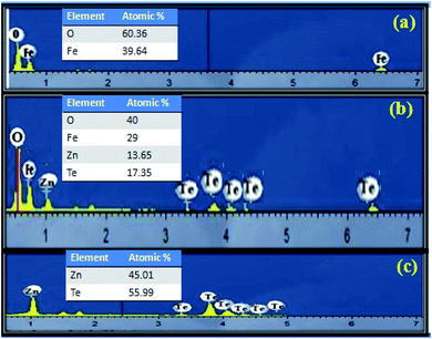 |
| | Fig. 3 EDX images of (a) α-Fe2O3, (b) α-Fe2O3/ZnTe and (c) ZnTe. | |
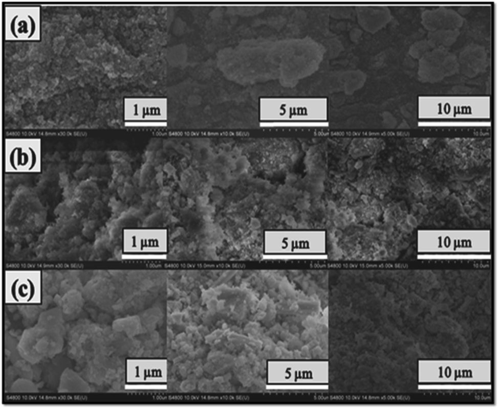
The morphology of all the nanomaterials (α-Fe2O3, α-Fe2O3/ZnTe and ZnTe) was analyzed from the SEM images. Random morphology with reasoning is explained in the discussion part (Fig. 4a–c).
 |
| | Fig. 4 SEM images of (a) α-Fe2O3 agglomerated NPs at resolution 1, 5 and 10 μm, (b) α-Fe2O3 decorated ZnTe at resolution 1, 5 and 10 μm and (c) ZnTe at resolution 1, 5 and 10 μm. | |
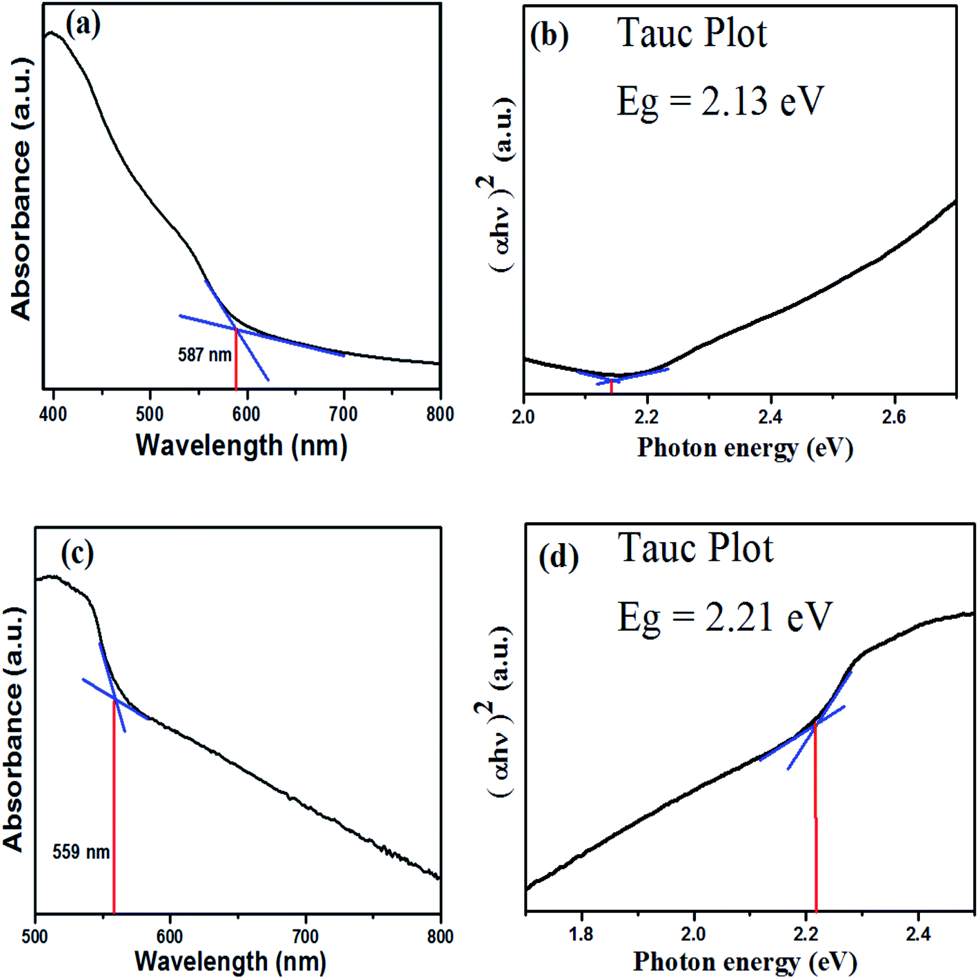
UV-visible DRS was employed to investigate the optical properties of the synthesized photocatalysts (Fig. 5). UV/Vis DRS encompasses the reflectance factor rather than the absorption factor and is calculated via the Kubelka–Munk expression.29
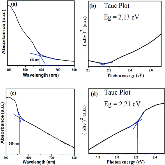 |
| | Fig. 5 UV/Vis diffuse reflectance spectra and Tauc plots. (a) UV/Vis plot of α-Fe2O3, (b) Tauc plot of α-Fe2O3, (c) UV/Vis plot of ZnTe, and (d) Tauc plot of ZnTe. | |
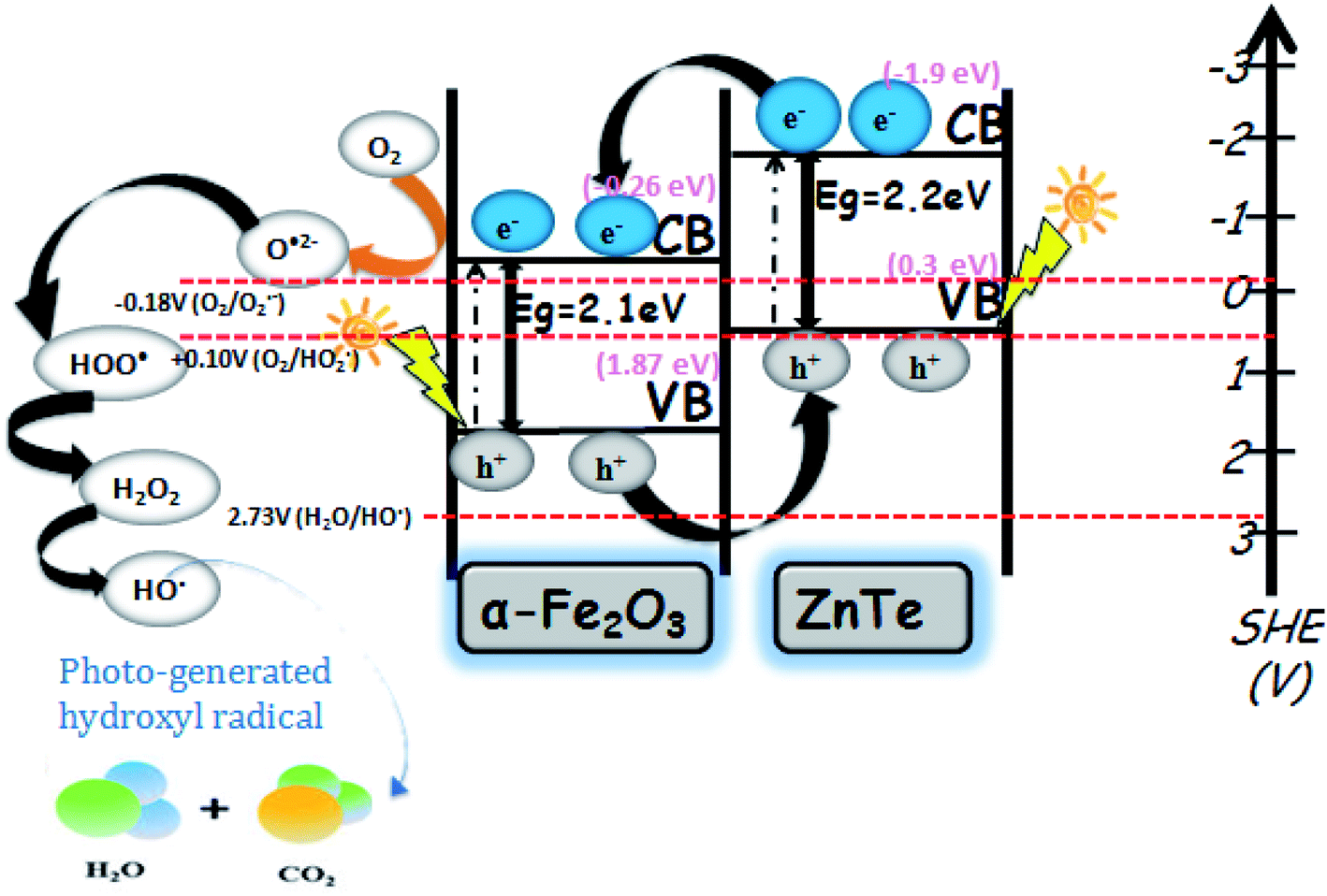
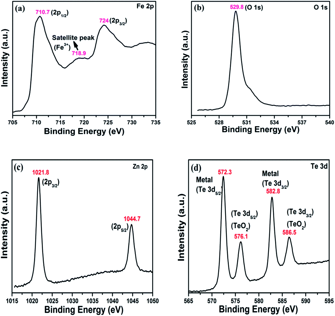
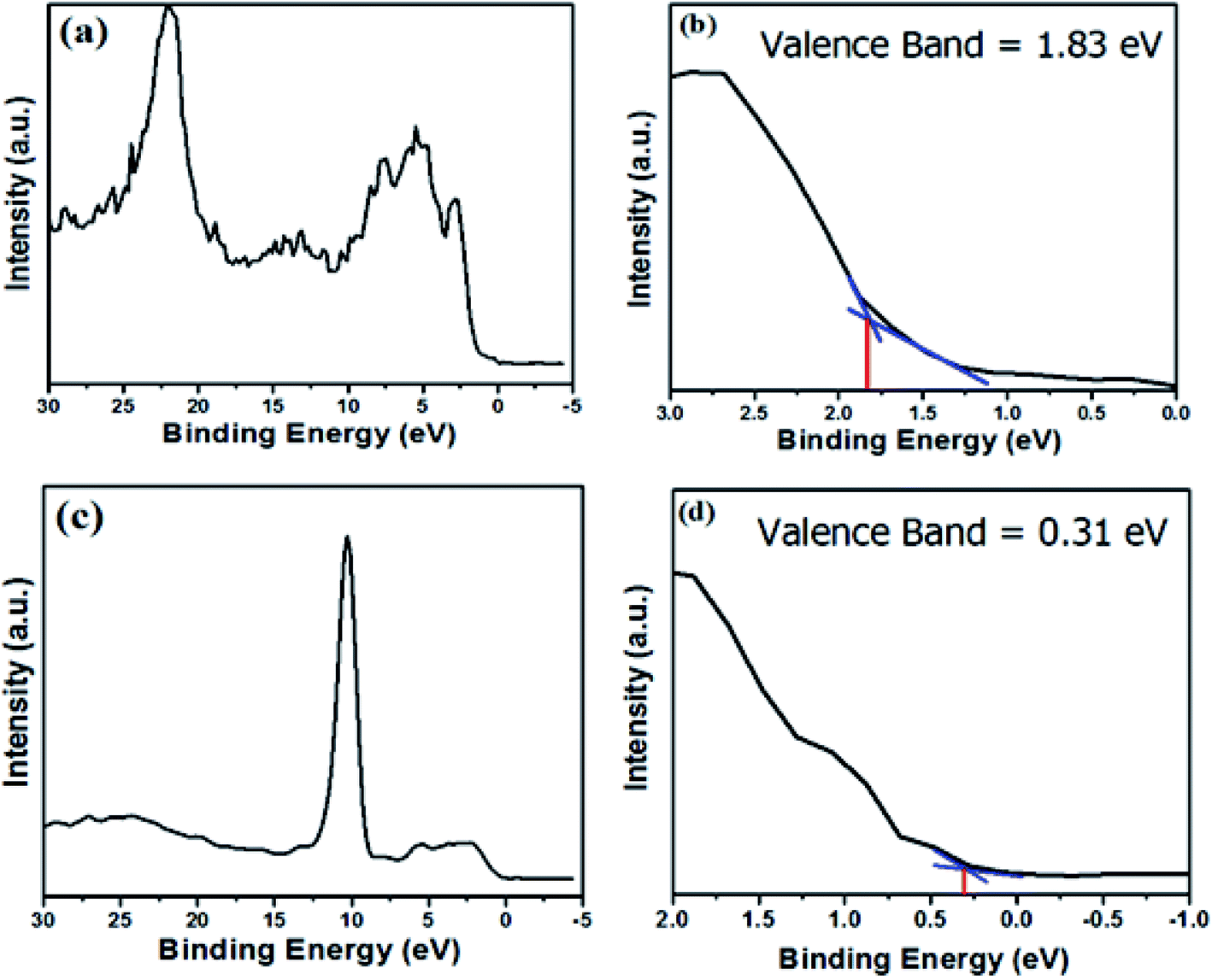
XPS analysis was employed to characterize the valence band positions (Fig. 6). The activity of any photocatalyst can be investigated through the alignment of the energy levels, i.e. its valence and conduction band position. The valence band position spectra of hematite and zinc telluride are shown in Fig. 7a and c. Fig. 7b and d are the zoomed-in plots for the valence band positions of α-Fe2O3 and ZnTe, which are measured to be 1.87 eV and 0.31 eV, respectively.
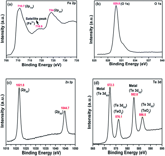 |
| | Fig. 6 XPS spectra of the as-prepared α-Fe2O3 and ZnTe. (a) Fe 2p, (b) O 1s, (c) Zn 2p, and (d) Te 3d. | |
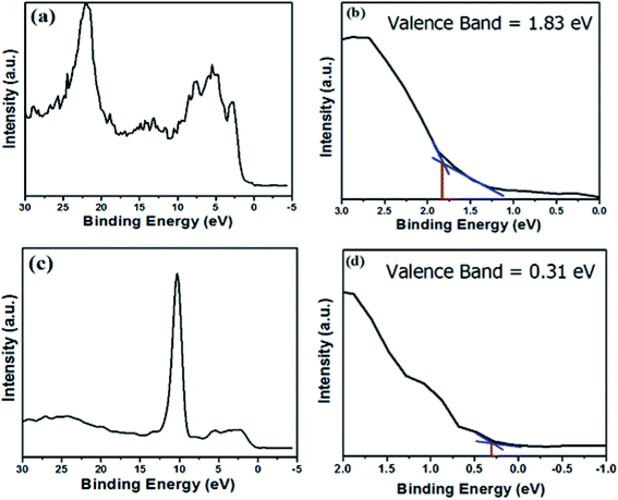 |
| | Fig. 7 Valence band spectra and zoomed-in valence band edges of α-Fe2O3 and ZnTe. (a) and (c) Valence band spectra of α-Fe2O3 and ZnTe, respectively; (b) and (d) zoomed-in valence band edges of α-Fe2O3 and ZnTe, respectively. | |
By utilizing the valence band position values (XPS analysis) and calculated band gap values (UV-Vis analysis), we have calculated the conduction band positions of both photocatalysts. The conduction band values for α-Fe2O3 and ZnTe were found to be −0.26 and −1.9 respectively.
4 Discussion
From the XRD patterns, it was found that all peaks with hkl values, i.e. (012), (104), (110), (113), (024), (116), (018), (214), (300), (208), were accordantly matched with the reported reference pattern of α-Fe2O3 having JCPDS card # 01-089-0598. The crystal system was rhombohedral with lattice parameters a = b = 5.038 Å, and c = 13.77 Å; where, α = β = 90° and γ = 120° (Fig. 2a). Fig. 2c shows the typical diffraction pattern of cubic ZnTe, prepared at 120 °C for 2 h. All of the peaks correspond to cubic ZnTe with a lattice constant of 6.128 Å and lattice angle of 90°, which were indexed to the standard diffraction pattern with file no. 03-065-0385.31
With critical analysis of the XRD spectrum of the nanocomposite, i.e. ZnTe/α-Fe2O3, it is inferred that the peaks at angles of 25°, 29°, 42° and 49° correspond to the characteristics peaks of ZnTe, while the peaks at angles of 33°, 35°, 41°, 49°, 53° and 57° correspond to the peaks of hematite, which confirms that the ZnTe/α-Fe2O3 photocatalyst has been synthesized successfully. In the diffraction pattern of the nanocomposite, it can clearly be seen that the peak along the (200) plane is more intense as compared to bare ZnTe, which can clearly be indicated by ( ).
).
The mechanism behind this apparent diversity is that the peak intensity refers to the distribution of atoms within the lattice. This intense peak can be attributed to the hematite exhibiting preferred orientation in the case of the nanocomposite. Typically, ZnTe shows growth along the (111), (220) and (311) planes, which are its exposed facets ( ). But owing to the preferred orientation and masking ability of hematite, it caps the exposed facets of ZnTe, thus limiting the growth of ZnTe at exposed sites, and inducing its growth along the (200) plane. Masking agents are strong binding molecules that cover the particle surface, and prevent them from growing. The role of hematite as a capping agent is supported by the literature as well.34
No impurity peaks, i.e., no unreacted metal atoms like tellurium, iron or zinc, were observed in the case of the bare (ZnTe and α-Fe2O3) photocatalysts. This confirms the purity of both bare samples. However, the diffraction peak at 23° in the NC is attributed to bare hematite (α-Fe2O3). This XRD peak is actually shifted to lower 2θ owing to a number of reasons: (1) In some cases the peak positions can vary due to experimental errors (such as zero error or displacement, mainly due to problems during the packing of the sample in the sample holder). (2) Heating of the sample may cause coalesce of the grain boundaries, meaning that d changes, which can lead to shifting of the peaks. (3) Peak shifting may relate either to instrumental causes or internal effects of the sample. (4) When you are scanning with XRD, the orientation of your sample does not change, and it should not be tilted because a tilt in the placed sample can also result in a shift in the XRD peak.31 Moreover, the sharp peaks from all the diffraction patterns confirm the highly crystalline nature of the as-synthesized photocatalysts. The avg. crystallite size calculated by using the Scherrer formula shows that the synthesized samples are in the nano range (Table 1).
Energy dispersive X-ray spectroscopy was utilized to reveal the precise distribution of elements and purity of the synthesized materials. The EDX spectrum illustrates the purity of all of the samples, as in the hematite nanomaterial only Fe and O are present (O: 60.36%; Fe: 39.64%), and in bare ZnTe all the peaks in the spectrum correspond to tellurium and zinc. The elemental composition of zinc and telluride is 41.01 and 58.99 atomic percentage, respectively. Moreover, the spectrum of the heterostructure clearly shows the peaks of all elements, i.e. O, Fe, Zn and Te, confirming the successful synthesis of the α-Fe2O3/ZnTe nanocomposite with 100% purity and the elemental composition of the composite is in good agreement with the synthesis scheme (Fig. 3a–c).
The morphology of α-Fe2O3 is agglomerated spherical nanoparticles as can be seen from Fig. 4a. The formation of aggregated α-Fe2O3 nanoparticles can be well explained by thermodynamic factors. The surface of the freshly prepared particle is highly activated. No stabilizing agents were used during the synthesis of hematite (α-Fe2O3). Thus, to lessen the total energy of the system, the particles are inclined to aggregate. This indicates that the driving force for this process is reduction in the surface energy by forming aggregates. So, a thermodynamically favorable process is driven. The morphology of pure ZnTe is irregular spherical nanoparticles as clearly seen from Fig. 4c. The SEM results of the α-Fe2O3/ZnTe heterostructure demonstrate that both nanoparticles are well adsorbed over each other with the assumed formation of a strong interface. The formation of this close interface between the two materials may facilitate the efficient transfer of electrons, thereby hindering the recombination of the charge carriers, and this could be the reason for the higher photocatalytic performance of the nanocomposite (Fig. 4b). The evidence for the role of hematite as a masking agent is clearly demonstrated in the SEM image in Fig. 4b of resolution 1 μm, where a chunk of ZnTe is covered by the agglomerated nanoparticles of hematite. These agglomerated NPs of hematite (α-Fe2O3) mask the exposed growth facet of ZnTe, which requires further investigation by HRTEM.
α-Fe2O3 shows a prominent absorption peak at ∼587 nm (Fig. 5a). The UV-Vis spectrum of α-Fe2O3 is divided into two regions on the basis of the type of possible transitions responsible for producing the absorption bands: (a) 380–470 nm and (d) 470–600 nm. The absorption band at region (a) is due to the charge transfer mechanism, i.e. the transfer of non-bonded electrons from O (2p) to Fe(III) metal. This is responsible for the absorption of hematite in the visible region.35 The absorption band at region (b) is due to the d–d transition or simultaneous excitations of two neighboring magnetically coupled Fe3+ cations. According to spin selection rules, the magnetically coupled transitions are allowed transitions. The higher the light absorption intensity, the darker the color of the compound will be. Thus, it contributes to the blood red color of hematite.36
The reflectance spectra of the hematite showed that the absorption at wavelength 587 nm was due to the transition of electrons from the valence band to the conduction band, thus corresponding to the band gap absorption of hematite. The band gap was calculated to be 2.13 eV by using the Tauc plot (Fig. 5b). Similarly, Fig. 5c is the DRS spectrum of ZnTe, which undoubtedly indicated that the zinc telluride nanoplates exhibited a prominent absorption in the visible region at ∼559 nm. The band gap for zinc telluride (ZnTe) was calculated to be ∼2.21 eV using the Tauc plot (Fig. 5d).
To determine the chemical composition, i.e. the oxidation state of Fe and O in α-Fe2O3 and the oxidation state of Zn and Te in ZnTe, XPS analysis was carried out. XPS (X-ray photoelectronic spectroscopy), one of the strongest techniques in the characterization of materials, was employed to further reveal the structural information of the product. The high-resolution spectra of Fe and O are shown in Fig. 6a and b. In the Fe 2p spectra, it is easy to observe that there are two obvious peaks for Fe at 724 and 710.5 eV, corresponding to the 2p3/2 and 2p1/2 shell of Fe2O3. Moreover, one satellite peak at 718.9 eV is evident, indicating the presence of Fe3+ ions of hematite (Fig. 6a). The O 1s spectrum shows a strong prominent peak of oxide at 529.9 eV, which corresponds to the lattice oxygen atom in α-Fe2O3. This indicates that the valence state of O is 2− (Fig. 6b).30
The Te 3d spectra show 2 Te binding energy peaks at 582.8 eV and 572.3 eV, which can be attributed to the Te 3d5/2 and Te 3d3/2, respectively, and are responsible for the 2− oxidation state of the tellurium ion in zinc telluride. These two peaks are accompanied by two photoelectron peaks at 586.5 and 576.1 eV, which are closely linked to emission from the 3d core levels of Te in an oxide environment. These tellurium oxide peaks (though with less intensity) are attributed to the 2− oxidation state of Te from its oxide, which might also be formed in very minute concentrations during the chemical synthesis. However, no such evidence has significantly been observed from other characteristic analytical techniques as shown in Fig. 6d. The Zn 2p spectrum shows two peaks at 1021.8 and 1044.7 eV, which are well attributed to the reported Zn 2p3/2 and Zn 2p1/2 signals, respectively, and correspond to the 2+ oxidation state of Zn in ZnTe37 (Fig. 6c).
XPS analysis was employed to characterize the valence band positions. The valence band positions of hematite and zinc telluride are at 1.87 eV and 0.31 eV, respectively. From this data, we have calculated the conduction band positions of both photocatalysts. The conduction band value for α-Fe2O3 and ZnTe was found to be −0.26 and −1.9, respectively (Fig. 7).
4.1. Degradation studies
The percentage degradation of the three dyes as a function of time was monitored by using α-Fe2O3, ZnTe and ZnTe-modified α-Fe2O3 photocatalysts, as shown in Fig. 8. Dye degradation studies were carried out up to 60 min. All of the results indicated that the composite showed higher photocatalytic activity than bare α-Fe2O3 and ZnTe. Thus, the order of degradation was found to be ZnTe < α-Fe2O3 < α-Fe2O3/ZnTe.
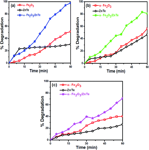 |
| | Fig. 8 Percentage degradation as a function of time: (a) Congo red, (b) methyl orange and (c) methylene blue. | |
α-Fe2O3 nanoparticles showed higher degradation than ZnTe because of the smaller band gap (Eg = 2.13 eV) allowing the generation of a large number of charge carriers under light irradiation. The maximum degradation was observed in the case of α-Fe2O3/ZnTe, due to the synergistic effect of both photocatalysts, which in-turn decreased the recombination rate by increasing the charge separation, thereby making more electrons and holes available to carry out the redox reactions at the two different photocatalysts. The other two possible reasons would be the large differences between the energy levels, i.e. the CB difference and VB difference of both materials. This factor also plays a key role in the enhanced photocatalytic activity, as the larger the difference is, the more thermodynamic force is provided to the electrons and holes to carry out the redox reaction, leading to the change of the growth facet of ZnTe along the (200) plane in the case of NC. However, this deduction still requires further investigation.
Based on the above experimental results, a possible mechanism is proposed in Fig. 9. The photocatalytic activity of the photocatalysts is closely related to the alignment of its band energy levels, which are estimated by UV-Vis diffuse reflectance spectra and XPS in this work. For both α-Fe2O3 and ZnTe, the band gap values (Eg) were thus estimated respectively to be 2.13 and 2.21 eV using the Tauc plots. Both bare samples are visible light active and capable of producing electrons (e−) and holes (h+). The valence band maximum for ZnTe calculated from XPS is 0.31 eV, while that of α-Fe2O3 is 1.87 eV. As the conduction band and valence band of ZnTe (−1.9 eV and 0.31 eV) are more negative than those of α-Fe2O3 (−0.26 eV and 1.87 eV), the photogenerated electrons move from ZnTe(CB) to α-Fe2O3(CB).38 Meanwhile, the migration of holes is in the opposite direction, i.e. α-Fe2O3(VB) to ZnTe(VB). This migration and separation of electrons and holes is achieved via the heterojunction interface. The heterojunction interface is established when two types of semiconductor photocatalysts combine together. As a result of this heterojunction, electrons (e−) and holes (h+) are redistributed on different sides of the heterojunction.39 Accordingly, it hinders the recombination process. In addition to this, production of specific types of ROS (e.g., ˙OH, 1O2, or ˙O2−) on the metal oxide based nanocomposites under illumination could be related to the electronic structures of the metal oxides in the nanocomposites and the redox potentials (EH) of the different ROS generation reactions.40,41 The relative energy position of the valence band (Ev) or conduction band (Ec) versus the standard redox potential (E0) is fundamental to determine the feasibility of electron transfer between the metal oxide and adsorbed substances. The photogenerated electrons in the conduction band for Fe2O3 have sufficient energy to reduce oxygen-containing species to form the corresponding ROS, as it is clearly shown in Fig. 9. This might happen owing to the ECB values of α-Fe2O3, i.e. −0.26, being more negative than the redox potential (EH) value of (O2/˙O2−), i.e. −0.18.54 Therefore, the reducing power of photoexcited α-Fe2O3 is sufficient to reduce environmentally dissolved oxygen, since we studied the degradation in an aerobic environment, thus generating the superoxide radical (˙O2−), which acts as a primary reactive oxygen species to carry out the degradation. Furthermore, the superoxide radical (˙O2−), by series of reactions, generates hydroxyl radicals.42 However, this needs to be investigated by EPR. ZnTe holes are not capable of oxidizing water. These findings are also in agreement with previously published reports. Hongxia Zhao and co-workers found photoinduced formation of reactive oxygen species and electrons from a metal oxide–silica (α-Fe2O3/SiO2) nanocomposite. An EPR spin-trapping study confirmed the ˙O2− formation on the α-Fe2O3 photocatalyst, which further carried out degradation phenomena. The photocatalytic degradation of a representative pollutant, bisphenol A, was used to check the photocatalytic activity of Fe2O3–SiO2.43 In another work, Gen Li et al. proposed the hematite/sulfite photosystem for selective pollutant degradation. Based on the positions of the VBM as well as the CBM vs. SHE of the individual constituents in their nanocomposite system, they found the formation of superoxide radicals (˙O2−) in α-Fe2O3, the signal of which is clearly observed in the EPR spectra. The photoexcited electrons can react with oxygen to form superoxide radicals (˙O2−) and can finally generate OH˙. This may play an important role in pollutant degradation, evidenced from EPR spectra. The results demonstrated that roxarsone (ROX), an aromatic organo-arsenic pollutant, could be effectively degraded by this system.44
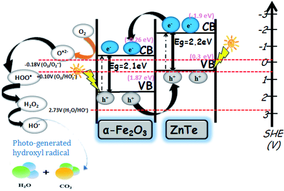 |
| | Fig. 9 Proposed mechanism for the photocatalytic degradation of dyes over the ZnTe-modified α-Fe2O3 nanocomposite. | |
The possible mechanism can be explained in equation form [eqn (18)–(25)].
| | |
Photocatalyst + hν → photocatalyst (e− + h+)
| (18) |
| | |
ZnTe(e−) + α-Fe2O3 → ZnTe + α-Fe2O3(e−)
| (19) |
| | |
α-Fe2O3(h+) + ZnTe → ZnTe(h+) + α-Fe2O3
| (20) |
| | |
α-Fe2O3(e−) + O2 → α-Fe2O3 + O2˙−
| (21) |
| | |
O2˙− + H2O → H2O2 + HO˙ + OH−
| (22) |
| | |
H2O2 + α-Fe2O3(e−) → α-Fe2O3 + OH− + HO˙
| (23) |
| |
 | (24) |
| | |
HO˙ + naphthalene/benzene derivatives → CO2 + H2O
| (25) |
Compared with the previous reports about α-Fe2O3-based photocatalysts, the ZnTe/α-Fe2O3 showed superior degradation efficiency. This might be attributed to the synergistic effect of ZnTe and α-Fe2O3, which facilitates poor charge carrier recombination and results in higher photocatalytic response towards wastewater pollutants. The key rationale towards such improved photocatalytic response is the establishment of a type-II configuration in the α-Fe2O3/ZnTe heterostructure. Table 2 illustrates the different α-Fe2O3-based and some other nanocatalysts with their degradation (%) efficiency, along with some other modalities including time (min), light source and degraded pollutant.
Table 2 Comparison of the proposed research with previous reports
| Photocatalyst |
Time (min) |
Light source |
Pollutant |
Degradation (%) |
Ref. |
| Magnetic iron oxides/TiO2 |
90 |
250 W mercury lamp |
MB |
50–60 |
45 |
| α-Fe2O3–TiO2 |
100 |
400 W UV lamp |
MB |
81 |
46 |
| N–TiO2/NG |
3 h |
300 W Xe |
MB |
88% |
47 |
| Fe2O3/Cu2O |
140 |
150 W Xe (xenon) lamp |
RB and JG |
2 times higher than bare materials |
48 |
| TiO2–PVC |
2.5 h |
300 W iodine tungsten |
RhB |
80% |
49 |
| BiVO4@Bi2O3 |
12 h |
500 W Xe |
RhB |
90% |
50 |
| 2% Fe–ZnO |
140 |
150 W mercury light |
MB |
92 |
51 |
| g-C3N4–GO |
4 h |
500 W Xe |
MO |
92% |
52 |
| C3N4–CdS |
3 h |
300 W iodine tungsten |
RhB |
80% |
53 |
| CQDs/α-Fe2O3 |
— |
400 W halogen spotlight |
Organic compound |
97 |
47 |
| α-Fe2O3 nanorod/RGO |
120 min |
— |
Phenol |
67 |
39 |
| ZnTe/α-Fe2O3 |
60 |
300 W Xe lamp |
CR |
97.9 |
This work |
5 Conclusion
In the proposed endeavor, an efficient α-Fe2O3/ZnTe nanocomposite was synthesized by a simple and cost-effective hydrothermal process. The results reveal that in contrast to bare α-Fe2O3 and ZnTe samples, the modified α-Fe2O3/ZnTe nanocomposite exhibited higher dye degradation efficiency. The superior photocatalytic performance of the nanocomposite photocatalyst is ascribed to the redox processes occurring at two different semiconductor surfaces. Based on all significant findings in the results and discussion part, a possible mechanism in equation form is also proposed. Consequently, it is proved that α-Fe2O3/ZnTe is a robust and efficient photocatalytic system for in-time remediation of environmental pollutants, especially in wastewater treatment. Moreover, this modified and optimized photocatalyst is expected to be a future trend, since nanocomposite photocatalysts have shown much better performance than their bare counterparts.
Conflicts of interest
The authors declare no conflicts of interest.
References
- P. Li, Z. Wang, L. Yang, S. Zhao, P. Song and B. Khan, J. Membr. Sci., 2018, 555, 56–68 Search PubMed.
- D. E. Freedman, S. M. Riley, Z. L. Jones, J. S. Rosenblum, J. O. Sharp, J. R. Spear and T. Y. Cath, J. Water. Process. Eng., 2017, 18, 29–40 Search PubMed.
- L. Cermakova, I. Kopecka, M. Pivokonsky, L. Pivokonska and V. Janda, Sep. Purif. Technol., 2017, 173, 330–338 Search PubMed.
- C. Y. P. Ayekoe, D. Robert and D. G. Lanciné, Catal. Today, 2017, 281, 2–13 Search PubMed.
- J. M. Dickhout, J. Moreno, P. Biesheuvel, L. Boels, R. G. Lammertink and W. M. de Vos, J. Colloid Interface Sci., 2017, 487, 523–534 Search PubMed.
- M. B. Heeb, I. Kristiana, D. Trogolo, J. S. Arey and U. Von Gunten, Water Res., 2017, 110, 91–101 Search PubMed.
- A. Di Paola, E. García-López, G. Marcì and L. Palmisano, J. Hazard. Mater., 2012, 211, 3–29 Search PubMed.
- S. Chakrabarti and B. K. Dutta, J. Hazard. Mater., 2004, 112, 269–278 Search PubMed.
- M. Shanthi and V. Kuzhalosai, Indian J. Chem., 2012, 51, 428–438 Search PubMed.
- E. Yassıtepe, H. Yatmaz, C. Öztürk, K. Öztürk and C. Duran, J. Photochem. Photobiol., A, 2008, 198, 1–6 Search PubMed.
- M. Amini and M. Ashrafi, Nanochem Res., 2016, 1, 79–86 Search PubMed.
- K. Yadav, M. Giri and N. Jaggi, Res. Chem. Intermed., 2015, 41, 9967–9978 Search PubMed.
- T. Yao, Q. Zhao, Z. Qiao, F. Peng, H. Wang, H. Yu, C. Chi and J. Yang, Chem.–Eur. J., 2011, 17, 8663–8670 Search PubMed.
- M. S. Khan, M. N. Ashiq, M. F. Ehsan, T. He and S. Ijaz, RSC Adv., 2014, 487, 202–209 Search PubMed.
- M. Mishra and D.-M. Chun, Appl. Catal., A, 2015, 498, 126–141 Search PubMed.
- J. Lian, X. Duan, J. Ma, P. Peng, T. Kim and W. Zheng, ACS Nano, 2009, 3, 3749–3761 Search PubMed.
- A. K. Patra, S. K. Kundu, A. Bhaumik and D. Kim, Nanoscale, 2016, 8, 365–377 Search PubMed.
- J. Yu, X. Yu, B. Huang, X. Zhang and Y. Dai, Cryst. Growth Des., 2009, 9, 1474–1480 Search PubMed.
- L. S. Zhong, J. S. Hu, H. P. Liang, A. M. Cao, W. G. Song and L. J. Wan, Adv. Mater., 2006, 18, 2426–2431 Search PubMed.
- M. Khedr, K. A. Halim and N. k. Soliman, Mater. Lett., 2009, 63, 598–601 Search PubMed.
- J. Su, J. Wang, C. Liu, B. Feng, Y. Chen and L. Guo, RSC Adv., 2016, 6, 101745–101751 Search PubMed.
- Y. Zhang, S. Jiang, W. Song, P. Zhou, H. Ji, W. Ma, W. Hao, C. Chen and J. Zhao, Energy Environ. Sci., 2015, 8, 1231–1236 Search PubMed.
- F. Meng, J. Li, S. K. Cushing, J. Bright, M. Zhi, J. D. Rowley, Z. Hong, A. Manivannan, A. D. Bristow and N. Wu, ACS Catal., 2013, 3, 746–751 Search PubMed.
- X. Liu, A. Jin, Y. Jia, J. Jiang, N. Hu and X. Chen, RSC Adv., 2015, 5, 92033–92041 Search PubMed.
- T. C. Araújo, H. d. S. Oliveira, J. J. S. Teles, J. D. Fabris, L. C. Oliveira and J. P. de Mesquita, Appl. Catal., B, 2016, 182, 204–212 Search PubMed.
- M. Niu, F. Huang, L. Cui, P. Huang, Y. Yu and Y. Wang, ACS Nano, 2010, 4, 681–688 Search PubMed.
- W. Wu, S. Zhang, X. Xiao, J. Zhou, F. Ren, L. Sun and C. Jiang, Nanoscale Res. Lett., 2012, 4, 3602–3609 Search PubMed.
- M. F. Ehsan and T. He, Appl. Catal., B, 2015, 166, 345–352 Search PubMed.
- M. F. Ehsan, M. N. Ashiq and T. He, RSC Adv., 2015, 5, 6186–6194 Search PubMed.
- W. Zhu, X. Cui, X. Liu, L. Zhang, J.-Q. Huang, X. Piao and Q. Zhang, Nanoscale Res. Lett., 2013, 8, 2 Search PubMed.
- M. F. Ehsan, R. Khan and T. He, ChemPhysChem, 2017, 18, 3203–3210 Search PubMed.
- P. S. Shinde, G. H. Go and W. J. Lee, J. Mater. Chem., 2012, 22, 10469–10471 Search PubMed.
- Y. Chen and C. C. Lin, Phys. Chem. Miner., 2014, 41, 727–736 Search PubMed.
- M. F. Ehsan, M. N. Ashiq, F. Bi, Y. Bi, S. Palanisamy and T. He, RSC Adv., 2014, 4, 48411–48418 Search PubMed.
- J. Wang, W. B. White and J. H. Adair, J. Am. Ceram. Soc., 2005, 88, 3449–3454 Search PubMed.
- G.-Y. Zhang, Y. Feng, Y.-Y. Xu, D.-Z. Gao and Y.-Q. Sun, Mater. Res. Bull., 2012, 47, 625–630 Search PubMed.
- M. Foad, M. Watt, A. Smart, C. S. Torres, C. Wilkinson, W. Kuhn, H. Wagner, S. Bauer, H. Leiderer and W. Gebhardt, Semicond. Sci. Technol., 1991, 6, A115 Search PubMed.
- R. C. Pawar, Y. Pyo, S. H. Ahn and C. S. Lee, Appl. Catal., B, 2015, 176, 654–666 Search PubMed.
- P. K. Gajendra, P. Deepak and P. Kulamani, ACS Appl. Mater. Interfaces, 2013, 5, 1–34 Search PubMed.
- C. D. Vecitis, K. R. Zodrow and S. Kang, ACS Nano, 2010, 4, 5471–5479 Search PubMed.
- M. Gratzel, Photoelectrochemical cells. In Materials For Sustainable Energy: A Collection of Peer-Reviewed Research and Review Articles, Nature, 2001, 414, 338–344 Search PubMed.
- B. Y. Yu and S. Y. Kwak, J. Mater. Chem., 2012, 22, 8345–8353 Search PubMed.
- H. Zhao, X. Chen, X. Li, C. Shen, B. Qu, J. Gao, J. Chen and X. Quan, Appl. Surf. Sci., 2017, 416, 281–287 Search PubMed.
- G. Li, C. Wang, Y. Yan, X. Yan, W. Li, X. Feng, J. Li, Q. Xiang, W. Tan and F. Liu, Chem. Eng. J., 2020, 386, 124007 Search PubMed.
- W. Wu, X. Xiao, S. Zhang, F. Ren and C. Jiang, Nanoscale Res. Lett., 2011, 6, 1–15 Search PubMed.
- A. Abbasi, D. Ghanbari, M. Salavati-Niasari and M. Hamadanian, J. Mater. Sci.: Mater. Electron., 2016, 27, 4800–4809 Search PubMed.
- B. Yu, W. M. Lau and J. Yang, Nanotechnology, 2013, 24, 335705 Search PubMed.
- M. R. Abhilash, G. Akshatha and S. Srikantaswamy, RSC Adv., 2019, 9, 8557–8568 Search PubMed.
- D. Wang, L. Shi, Q. Luo, X. Li and J. An, J. Mater. Sci., 2012, 47, 2136–2145 Search PubMed.
- M.-L. Guan, D.-K. Ma, S.-W. Hu, Y.-J. Chen and S.-M. J. Huang, Inorg. Chem., 2011, 50, 800–805 Search PubMed.
- K. A. Isai and V. S. S. Shrivastava, SN Appl. Sci., 2019, 1, 1247 Search PubMed.
- Z. Tong, D. Yang, J. Shi, Y. Nan, Y. Sun and Z. Jiang, ACS Appl. Mater. Interfaces, 2015, 7, 25693–25701 Search PubMed.
- D. Wang, Z. Xu, Q. Luo, X. Li, J. An, R. Yin and C. Bao, J. Mater. Sci., 2016, 51, 893–902 Search PubMed.
- P. M. Wood, Biochem. J., 1988, 253, 287–289 Search PubMed.
|
| This journal is © The Royal Society of Chemistry 2020 |
Click here to see how this site uses Cookies. View our privacy policy here. 
 Open Access Article
 This Open Access Article is licensed under a Creative Commons Attribution-Non Commercial 3.0 Unported Licence
 ab,
Zhan Wang
ab,
Zhan Wang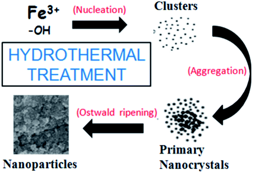


 ).
). ). But owing to the preferred orientation and masking ability of hematite, it caps the exposed facets of ZnTe, thus limiting the growth of ZnTe at exposed sites, and inducing its growth along the (200) plane. Masking agents are strong binding molecules that cover the particle surface, and prevent them from growing. The role of hematite as a capping agent is supported by the literature as well.34