 Open Access Article
Effect of curing conditions on the cutting resistance of fabrics coated with inorganic-powder-reinforced epoxy composite
Xuefeng Yana,
Leilei Wua,
Shanshan Jinb,
Wei Zhaoc,
Haijian Caoa and
Yan Ma *a
*a
aNational & Local Joint Engineering Research Center of Technical Fiber Composites for Safety and Protection, School of Textile and Clothing, Nantong University, Nantong 226019, P. R. China. E-mail: mayan0416@ntu.edu.cn
bToray Fiber Research Center, Nantong 226009, China
cSelect (Nantong) Safety Product Co., Ltd., Nantong 226000, P. R. China
First published on 11th September 2020
Abstract
Inorganic powders (IPs), namely, SiO2 and Al2O3, were used as reinforcements and thermosetting epoxy resin was utilized as a matrix to manufacture IP/epoxy preform, which was coated on the surfaces of 2/1 twill woven polyethylene terephthalate (PET) fabrics before the final curing process. The effect of curing conditions, including temperature, time, and IP content, on the physical, mechanical, and cutting resistance properties of pure IP/epoxy composites and PET fabrics coated with IP/epoxy composites were investigated. Results indicated that the cutting resistance of PET fabrics could be greatly improved by coating with IP/epoxy composites. Meanwhile, the cutting resistance of fabrics coated with IP/epoxy composites had a close relationship with the shore hardness of the coated IP/epoxy composites, which could be controlled by the curing conditions and IP content.
Introduction
Stringent gun control legislations in many countries have helped reduce hand-gun attacks against police officers. However, cutting assaults remain a likely threat that is growing rapidly.1 Security officers, such as soldiers and police, may encounter various cutting threats, including direct attacks from sharpened instruments and knives, and physical contact with sharp objects, for example, broken glass, debris, and razor wire.1 Cutting refers to interactions with a sharp-edged instrument and includes slashing and knife stabbing threats.2 Stabbing refers to cutting actions wherein an edged weapon travels mainly in a direction vertical to a protective surface. Slashing refers to cutting actions wherein an edged weapon travels mainly along a protective surface. Advanced technologies for resisting knife stabs include metal ring meshes, flexible rigid metal or ceramic element arrays, or thermoplastic-coated fabrics.3Several layers of conventional ballistic fabrics, fabrics that contain hardened metal wires,4 high-performance fibers,4,5 or specially knitted fabrics,5,6 can provide reasonable protection against slashing. The use of multiple layers of the above fabrics is well known as one of most effective ways to protect against slashing. However, multiple layers of fabrics limit body movement during their service life. Body movement is a comfort characteristic that decides the acceptance of fabrics by wearers.
Slash protection can be achieved by using numerous textile structures through several appropriate methods, such as combining fibers,7 designing structures,6 and finishing.8 High-performance fibers, including ultrahigh-molecular-weight polyethylene4 and Kevlar,4,5,8 are mainly utilized to manufacture fabrics through designing special dense structures, such as triaxial woven,9 3D knitted4,6 and 3D woven10 structures, for cut protection. In contrast to the use of multiple layers of traditional fabrics, the use of the above fabrics can improve comfort characteristics, such as movement flexibility and breathability. However, these fabrics still fail to meet the comfort demand owing to their dense structures. Plastic coating methods are also used to treat fabrics to retain flexibility and improve cutting resistance properties. Jessie11 attempted to improve the stab and puncture characteristics of aramid fabrics through coverage with thermoplastic resin films via hot press methods and confirmed the positive effects of thermoplastic-coated methods on improving the cutting resistance properties of fabrics. Plastics can be divided into two types: thermoplastic and thermosetting. Thermosetting plastics possess numerous advantages over thermoplastic ones. These advantages include excellent mechanical, adhesion, and finishing properties and resistance to solvents, corrosives, and heat.12,13 The effects of thermosetting-coating methods on the cutting resistance properties of fabrics have been investigated in numerous studies,11 which indicated that thermosetting-coated fabrics exhibit superior cutting resistance performance. However, the presence of continuous thermoplastic and thermosetting plastic layers on the surfaces of textiles still limits flexibility and breathability. Therefore, the continuous plastic layer on fabrics is divided into discontinuous guard plates that have small gaps between each plate to retain flexibility and breathability. The properties, such as the shore hardness and mechanical performance of guard plates, should be improved through various techniques to ensure the cutting resistance of the above-mentioned composite fabrics. In the past decades, inorganic powders (IPs), such as Al2O3, CaCO3, ZnO, and glass, have been widely utilized to reinforce plastics, especially epoxy resin, to improve their mechanical,14–16 structural,14 thermal,14,15,17 morphological,14,16 and tribological properties18 and hardness.19 The hardness of plastics is closely related to their slashing resistance.
Polyethylene terephthalate (PET) is one of the most important raw materials that are widely used as liners for protective fabrics because of their low cost, excellent mechanical properties, and chemical stability. In the present work, IPs, namely, SiO2 and Al2O3 powders, were used as reinforcements and epoxy resin was applied as a matrix to manufacture IP/epoxy preform, which was directly coated on the surfaces of traditional 2/1 twill woven PET fabrics before the final curing process. This work aimed to investigate the effect of curing conditions on the cutting resistance properties of IP-reinforced, epoxy-resin-coated fabrics. The effect of curing conditions, including temperature and time, on the mechanical properties, surface hardness, and cutting resistance, of pure IP/epoxy composites and fabrics coated with IP/epoxy composites were investigated through three-point bending tests, shore hardness tests, and cut protection performance (CPP) tests, respectively.
Materials and experimental procedures
Materials
Bisphenol A diglycidyl ether epoxy resin (E51), which was selected as the resin matrix, was supplied by Nantong Xingchen Synthetic Material Co., Ltd (Jiangsu, China). Dicyandiamide was chosen as the curing agent and supplied by Shanghai EMST Electronic Material Co., Ltd. IPs, including SiO2 and Al2O3 as reinforcements, were purchased from Alfa Aesar Co., Ltd (Beijing, China). The SiO2 and Al2O3 powders had average particle sizes of 60–80 and 80–100 μm, respectively, and densities of 2.20 and 3.89 g cm−3, respectively. The purities of SiO2 and Al2O3 exceeded 99%. The silane coupling agent γ-aminopropyl triethoxy silane (KH-560) was procured from Nanjing Shuguang Chemical Group Co., Ltd. (Jiangsu, China) and used to improve the bonding between IP and epoxy resin. Woven PET fabrics (76 × 68, 100 g m−2) were supplied by Wujiang Zhongpeng Textile Co., Ltd. (Jiangsu, China) and used as base fabrics.Preparation of IP/epoxy composites and PET fabrics coated with IP/epoxy
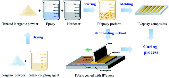
As shown in Fig. 1, SiO2 and Al2O3 IPs with the weight ratio of 4![[thin space (1/6-em)]](https://www.rsc.org/images/entities/char_2009.gif) :
:![[thin space (1/6-em)]](https://www.rsc.org/images/entities/char_2009.gif) 1 were immersed in silane coupling agent at room temperature for 4 h. The treated IPs were dried at 80 °C for 40 min in an oven. Finally, the IP/epoxy preform was obtained by mixing the epoxy resin, curing agent, and treated IPs at the weight ratio of 100
1 were immersed in silane coupling agent at room temperature for 4 h. The treated IPs were dried at 80 °C for 40 min in an oven. Finally, the IP/epoxy preform was obtained by mixing the epoxy resin, curing agent, and treated IPs at the weight ratio of 100![[thin space (1/6-em)]](https://www.rsc.org/images/entities/char_2009.gif) :
:![[thin space (1/6-em)]](https://www.rsc.org/images/entities/char_2009.gif) 10
10![[thin space (1/6-em)]](https://www.rsc.org/images/entities/char_2009.gif) :
:![[thin space (1/6-em)]](https://www.rsc.org/images/entities/char_2009.gif) 22–33 through stirring. The IP/epoxy preform was poured into a square mold with dimensions of 80 × 10 × 2 mm3 and then transferred to an oven for curing. In accordance with the actual curing situation, the curing temperature and time were set as 60–160 °C and 20–100 min, respectively. The blade coating method was used to manufacture the PET fabrics coated with IP/epoxy preform. Then, the fabrics were moved to the oven for the curing process. The curing temperature and time were set as 100–120 °C and 20–40 min, respectively. The detailed curing conditions for IP/epoxy preform and PET fabrics coated with IP/epoxy perform are shown in Table 1.
22–33 through stirring. The IP/epoxy preform was poured into a square mold with dimensions of 80 × 10 × 2 mm3 and then transferred to an oven for curing. In accordance with the actual curing situation, the curing temperature and time were set as 60–160 °C and 20–100 min, respectively. The blade coating method was used to manufacture the PET fabrics coated with IP/epoxy preform. Then, the fabrics were moved to the oven for the curing process. The curing temperature and time were set as 100–120 °C and 20–40 min, respectively. The detailed curing conditions for IP/epoxy preform and PET fabrics coated with IP/epoxy perform are shown in Table 1.
| IP/epoxy preform | Time (min) | |||||||
|---|---|---|---|---|---|---|---|---|
| Temp (°C) | IP![[thin space (1/6-em)]](https://www.rsc.org/images/entities/char_2009.gif) : :![[thin space (1/6-em)]](https://www.rsc.org/images/entities/char_2009.gif) epoxy (wt%) epoxy (wt%) |
20 | 30 | 40 | 50 | 60 | 80 | 100 |
| 60 | 30 | × | × | × | √ | √ | √ | √ |
| 80 | 30 | √ | √ | √ | √ | √ | √ | √ |
| 100 | 30 | √ | √ | √ | √ | √ | × | × |
| 120 | 30 | √ | √ | √ | √ | √ | × | × |
| 140 | 30 | √ | √ | √ | √ | √ | × | × |
| 160 | 30 | √ | √ | √ | √ | √ | × | × |
| PET coated with IP/epoxy | 20 | 30 | 40 | 60 | 80 | 100 | 140 | 180 | |
|---|---|---|---|---|---|---|---|---|---|
| 60 | 20 | × | × | × | × | √ | √ | √ | √ |
| 25 | × | × | × | √ | √ | √ | √ | √ | |
| 30 | × | × | × | √ | √ | √ | √ | √ | |
| 80 | 20 | √ | √ | √ | √ | √ | × | × | × |
| 25 | √ | √ | √ | √ | √ | × | × | × | |
| 30 | √ | √ | √ | √ | √ | × | × | × | |
| 100 | 20 | × | × | √ | √ | √ | √ | × | × |
| 25 | × | × | √ | √ | √ | √ | × | × | |
| 30 | × | × | √ | √ | √ | √ | × | × | |
Optical and scanning electron microscopy observation
The surface of the PET fabrics without and with coating was examined by using optical microscopy (VHX-500F, KEYENCE Corporation, Japan) and Scanning Electron Microscopy (SEM, JEOL model JSM-5200, Japan). Prior to SEM observation, the samples were coated with gold.Shore hardness measurements
The hardness of IP-reinforced composites was determined and expressed as durometer hardness (Shore-D) on the basis of the ASTM D 2240 (ref. 20) method. At least five points of three samples for each type were measured by using a digital hardness tester (HLX-AC, Handpi, Yueqing, China).Three-point bending tests
Flexural tests were performed on the basis of ASTM D7264 (ref. 21) by subjecting at least five pieces of each type of specimen to the three-point bending test. The tests were carried out in a universal testing machine Instron 5969 (Instron, USA) equipped with a 5 kN load cell at a span length of 64 mm and a constant crosshead speed of 2 mm min−1 on the outer surface of the sample. The test was performed at room temperature in a relative humidity (RH)-controlled laboratory (23 ± 0.5 °C, 48% ± 2% RH). The bending test specimens had dimensions of 80 mm × 10 mm × 2 mm (length × width × thickness).Cutting resistance performance tests
Cutting resistance tests were carried out in accordance with the ASTM F 1790 standard22 by using a TDM-100 tomodynamometer (RGI Industrial Products, Canada). This method is based on the determination of the force necessary for a razor blade to cut through the specimen thickness after a sliding displacement of 20 mm at a constant rate of 150 mm min−1. The schematic of the cutting test principle is shown in Fig. 2(a). The apparatus propelled the cutting edge across the specimen until sufficient work was applied to cut through the specimen. The sample cut-through was detected through electrical contact. Blades were replaced after each test. Fifteen different values of the vertical force were applied on one type of specimen. The plot of applied load versus the normalized cut-through distance is presented in Fig. 2(b). The calculated cutting load could be obtained from the regression line.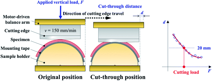 | ||
| Fig. 2 Schematic of the cutting test principle (a) and plot of applied load versus the normalized cut-through distance and resulting regression line and calculated cutting load (b). | ||
Results and discussion
Shore hardness of IP/epoxy composites
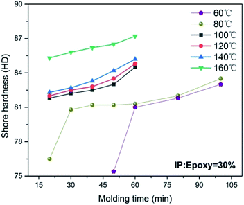
The shore hardness values of IP/epoxy composites (IP![[thin space (1/6-em)]](https://www.rsc.org/images/entities/char_2009.gif) :
:![[thin space (1/6-em)]](https://www.rsc.org/images/entities/char_2009.gif) epoxy ratio = 30 wt%) manufactured under different curing conditions are shown in Fig. 3. Evidently, the IP/epoxy composites manufactured at high curing temperatures and long curing times exhibited high shore hardness values. For IP/epoxy composites manufactured at 80 °C, shore hardness increased by approximately 4.6% from 76.5 HD (t = 20 min) to 80.2 HD (t = 30 min) within 10 min. Then, shore hardness increased by only 3.5% to 83.0 HD (t = 100 min) within 70 min after curing. A similar tendency was exhibited by the IP/epoxy composites manufactured at 60 °C as illustrated in Fig. 3. The relationship between the curing time and curing degree of polymers can be established by using a model-free kinetics approach.23 The curing degree of epoxy resin with IP fillers increased exponentially with the increase in curing time.24 The curing degrees and shore hardness values of IP/epoxy composites clearly exhibited the same response with the increase in curing time, which was dependent on the crosslinking degree of the epoxy resin.
epoxy ratio = 30 wt%) manufactured under different curing conditions are shown in Fig. 3. Evidently, the IP/epoxy composites manufactured at high curing temperatures and long curing times exhibited high shore hardness values. For IP/epoxy composites manufactured at 80 °C, shore hardness increased by approximately 4.6% from 76.5 HD (t = 20 min) to 80.2 HD (t = 30 min) within 10 min. Then, shore hardness increased by only 3.5% to 83.0 HD (t = 100 min) within 70 min after curing. A similar tendency was exhibited by the IP/epoxy composites manufactured at 60 °C as illustrated in Fig. 3. The relationship between the curing time and curing degree of polymers can be established by using a model-free kinetics approach.23 The curing degree of epoxy resin with IP fillers increased exponentially with the increase in curing time.24 The curing degrees and shore hardness values of IP/epoxy composites clearly exhibited the same response with the increase in curing time, which was dependent on the crosslinking degree of the epoxy resin.
The shore hardness values of IP/epoxy composites with different IP weight ratios (0, 20, 25, and 30 wt%) manufactured at 60 °C, 80 °C, and 100 °C are shown in Fig. 4(a), (b), and (c), respectively. The shore hardness of IP/epoxy was affected by curing temperature, curing time, and IP content. In detail, high curing temperatures and long curing times exerted positive effects on the improvement in the shore hardness of epoxy and IP/epoxy composites with different IP![[thin space (1/6-em)]](https://www.rsc.org/images/entities/char_2009.gif) :
:![[thin space (1/6-em)]](https://www.rsc.org/images/entities/char_2009.gif) epoxy ratios. Meanwhile, the addition of IPs improved the shore hardness values of epoxy under different curing conditions. For example, the shore hardness values of epoxy composites cured at 60 °C, 80 °C, and 100 °C for 80 min increased by 20.2% (69.9 HD to 84.0 HD), 10.0% (76.1 HD to 83.7 HD), and 7.6% (79.0 HD to 85.1 HD) after filling with IPs, respectively. Evidently, the positive effect of inorganic fillers on shore hardness weakened to a certain extent with the increase in curing temperature. The results indicated that the shore hardness of the IP/epoxy composite increased with the increase in IP filler content. This behavior corresponded to the high hardness and highly uniform dispersion of IP fillers. However, as IP content was increased, the rate of increase in shore hardness decelerated. Taking high shore hardness and low density into consideration, the IP
epoxy ratios. Meanwhile, the addition of IPs improved the shore hardness values of epoxy under different curing conditions. For example, the shore hardness values of epoxy composites cured at 60 °C, 80 °C, and 100 °C for 80 min increased by 20.2% (69.9 HD to 84.0 HD), 10.0% (76.1 HD to 83.7 HD), and 7.6% (79.0 HD to 85.1 HD) after filling with IPs, respectively. Evidently, the positive effect of inorganic fillers on shore hardness weakened to a certain extent with the increase in curing temperature. The results indicated that the shore hardness of the IP/epoxy composite increased with the increase in IP filler content. This behavior corresponded to the high hardness and highly uniform dispersion of IP fillers. However, as IP content was increased, the rate of increase in shore hardness decelerated. Taking high shore hardness and low density into consideration, the IP![[thin space (1/6-em)]](https://www.rsc.org/images/entities/char_2009.gif) :
:![[thin space (1/6-em)]](https://www.rsc.org/images/entities/char_2009.gif) epoxy ratio = 30 wt% was identified as the reasonable IP/epoxy ratio of the composites in the present study.
epoxy ratio = 30 wt% was identified as the reasonable IP/epoxy ratio of the composites in the present study.
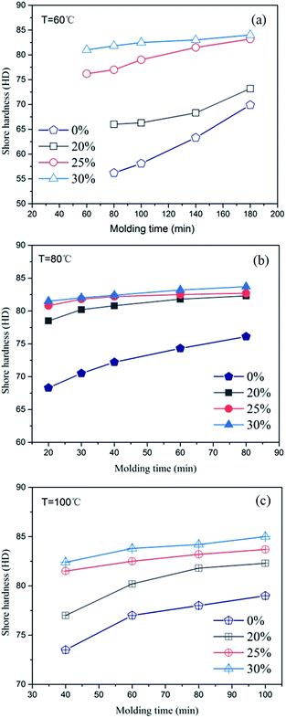 | ||
| Fig. 4 Effect of IP weight ratios on the shore hardness values of IP/epoxy composites at different curing temperatures, (a) T = 60 °C, (b) T = 80 °C, (c) T = 100 °C. | ||
Flexural mechanical properties of IP/epoxy composites
The three-point bending test was carried out to evaluate the flexural properties of IP/epoxy composites with IP![[thin space (1/6-em)]](https://www.rsc.org/images/entities/char_2009.gif) :
:![[thin space (1/6-em)]](https://www.rsc.org/images/entities/char_2009.gif) epoxy ratio = 30 wt%. The typical flexural stress–strain curves of IP/epoxy composites at different curing temperatures (100–120 °C) are shown in Fig. 5(a) to (c). The flexural strain–stress curves showed that IP/epoxy composites exhibited ductile behaviour at low curing temperatures and short curing times. The fracture behaviour of IP/epoxy composites transformed comparably brittle with the increasement of curing temperature and time.
epoxy ratio = 30 wt%. The typical flexural stress–strain curves of IP/epoxy composites at different curing temperatures (100–120 °C) are shown in Fig. 5(a) to (c). The flexural strain–stress curves showed that IP/epoxy composites exhibited ductile behaviour at low curing temperatures and short curing times. The fracture behaviour of IP/epoxy composites transformed comparably brittle with the increasement of curing temperature and time.
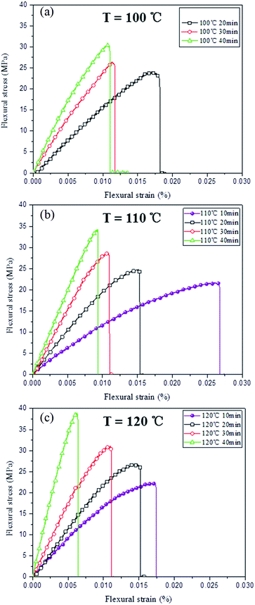 | ||
Fig. 5 Flexural strain–stress curves of IP/epoxy composites with IP![[thin space (1/6-em)]](https://www.rsc.org/images/entities/char_2009.gif) : :![[thin space (1/6-em)]](https://www.rsc.org/images/entities/char_2009.gif) epoxy ratio = 30 wt% manufactured at different curing temperatures, (a) T = 100 °C, (b) T = 110 °C, (c) T = 120 °C. epoxy ratio = 30 wt% manufactured at different curing temperatures, (a) T = 100 °C, (b) T = 110 °C, (c) T = 120 °C. | ||
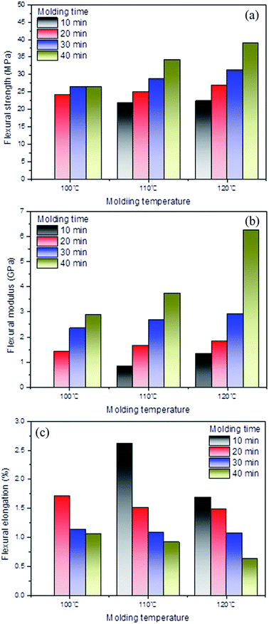
The flexural mechanical properties, including flexural modulus, flexural strength, and flexural strain at break, are shown in Fig. 6(a)–(c). The epoxy resin matrix was present as a continuous phase that dominated the mechanical properties of IP-filler-reinforced epoxy composites. These results indicated that the IP/epoxy composites manufactured at high curing temperatures and long times showed high flexural moduli and strengths but low flexural strains at break. These characteristics were consistent with the flexural properties of the pure matrix. In detail, the flexural moduli of the IP/epoxy composites cured at 100 °C, 110 °C and 120 °C increased to 86.2%, 140.1%, and 256.8% as the curing time was prolonged from 20 min to 40 min as illustrated in Fig. 6(a). Flexural strength correspondingly increased to 12.5%, 36.0%, and 44.4%, respectively, whereas flexural elongation decreased by 37.1%, 40.3%, and 56.7%, respectively.
Surface morphology of PET fabrics coated with IP/epoxy composites
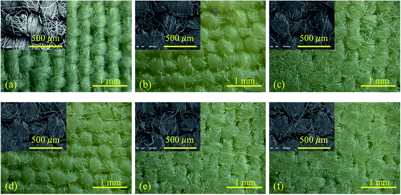
The optical and scanning electron microscopy observation on PET fabric and fabrics coated with IP/epoxy composites are shown in Fig. 7(a), (b) and (c), respectively. It is clear that epoxy resin reinforced by inorganic powder is covered the surface of PET fabric and impregnated into the PET fiber bundles after coating process. However, there is no obvious difference between PET fabrics coated with IP/epoxy composites at different curing conditions.Shore hardness of PET fabrics coated with IP/epoxy composites
The shore hardness values of PET fabrics coated with IP/epoxy composites (IP![[thin space (1/6-em)]](https://www.rsc.org/images/entities/char_2009.gif) :
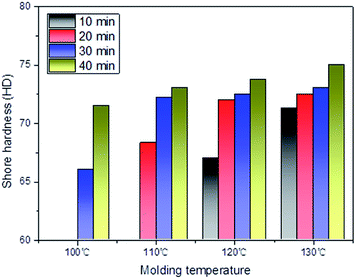
:![[thin space (1/6-em)]](https://www.rsc.org/images/entities/char_2009.gif) epoxy ratio = 30 wt%) are shown in Fig. 8. The tendency shown by the shore hardness of fabrics coated with IP/epoxy composites was similar to that shown by the shore hardness of IP/epoxy composites as illustrated in Fig. 4. In general, the fabrics coated with IP/epoxy composites cured at high temperatures and long durations exhibited high shore hardness. The shore hardness of fabrics coated with IP/epoxy composites showed a significant increase at the initial curing stage then gradually stabilized with the prolongation of curing time. The effect of curing temperature on shore hardness exhibited the same tendency.
epoxy ratio = 30 wt%) are shown in Fig. 8. The tendency shown by the shore hardness of fabrics coated with IP/epoxy composites was similar to that shown by the shore hardness of IP/epoxy composites as illustrated in Fig. 4. In general, the fabrics coated with IP/epoxy composites cured at high temperatures and long durations exhibited high shore hardness. The shore hardness of fabrics coated with IP/epoxy composites showed a significant increase at the initial curing stage then gradually stabilized with the prolongation of curing time. The effect of curing temperature on shore hardness exhibited the same tendency.
Cutting resistance of fabrics coated with IP/epoxy composites
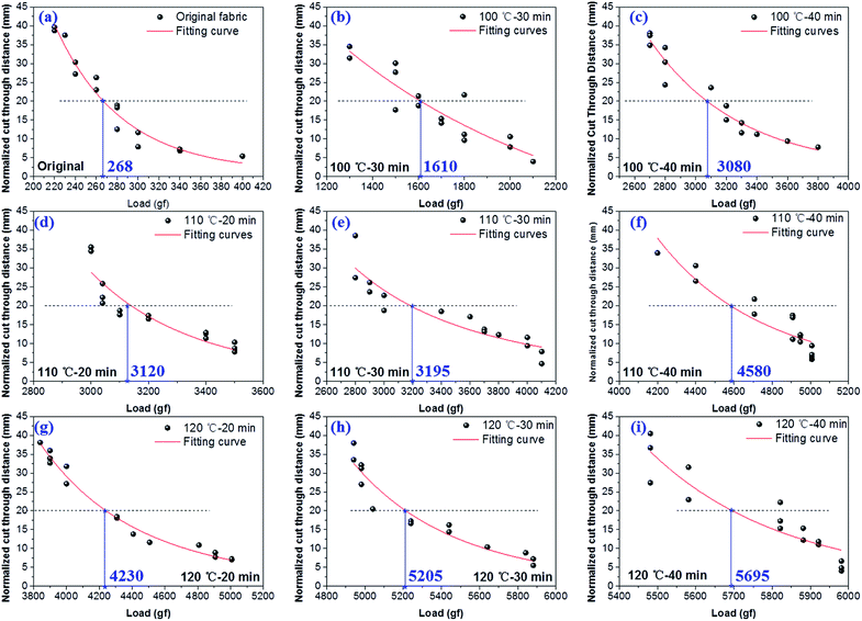
The plots of applied load versus the normalized cut-through distance of the original PET fabric and PET fabric coated with IP/epoxy composites are provided in Fig. 9(a) and (b–i), respectively. Cut-through distance obviously decreased with the increase in the applied vertical load on the blade. As shown in Fig. 9(a), the calculated cutting load of the original PET fabric was approximately 267 gf, which indicated that the original PET fabric could be cut through by a razor blade with a force of 267 gf after a sliding displacement of 20 mm at a constant rate of 150 mm min−1. The calculated cutting load of the PET fabric coated with IP/epoxy resin and manufactured under different conditions increased to 1610–5695 gf as depicted in Fig. 9(b)–(i). Coating with IP/epoxy composites was obviously an effective way to improve the cutting resistance of PET fabrics. Similar to shore hardness properties, the cutting resistance properties of PET fabrics coated with IP/epoxy composites were effectively enhanced by high curing temperatures and long curing times.The relationship between the shore hardness and cutting load of fabrics coated with IP/epoxy composites cured under different conditions is shown in Fig. 10. Shore hardness and cutting load had a linear relationship with a goodness of fit R2 = 88%. This result indicated that the cutting resistance of fabric coated with IP/epoxy composites increased with shore hardness.
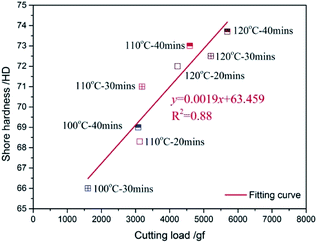 | ||
| Fig. 10 Relationship between the cutting loads and shore hardness values of fabrics coated with IP/epoxy. | ||
Understanding the parameters affect the cut resistance enables one to develop materials with high cut resistance. Lots of previous research has proved that intrinsic properties and structural factors contribute to the cut resistance, such as transverse compressive modulus, hardness, toughness, impact resistance, mobility, skin-core structure and so on. The cutting load of materials was success to improve up to 3000 gf by various methods including the addition of different fillers and compounding them with different yarns taking the above affecting parameters into consideration. The typical cutting resistance data onto various materials reported in reference and patents is shown in Table 2. It is clear that traditional nature and synthetic fibers, such as cotton, PET and high performance PE (HPPE), without any treatment exhibit limited cut protective performance and low cutting load under 600 gf. The cutting load of HPPE was improved from 600 gf to 1225 gf and 1593 gf by adding tungsten and alumina powder, respectively. The addition of tungsten and alumina powder is an effective way to adjust the transverse compressive modulus and hardness. The cutting load of PET was improved to 1440 gf by compounding with cutting resistance fiber (CRF). However, these methods still cannot meet the need of light, breathable and high cutting protective performance. In the present study, the cutting load of PET fabric was successfully improved approximately twenty times from 268 gf to 5695 gf through coating on PET fabrics with inorganic-powder-reinforced epoxy composite.
| Ex. | Fiber material | Construction | CL/CPP (gf) | Ref. | ||
|---|---|---|---|---|---|---|
| Filler in fiber | Filler size (μm) | Filler weight percentage | ||||
| a CL, cutting load; CPP, cut protective performance; HPPE, high-performance PE; CRF, cutting resistant fiber; UHMWPE, ultrahigh molecular weight polyethylene. | ||||||
| 1 | HPPE | Non | 0 | 0 | 250–600 | 25 |
| 2 | Tungsten | 0.6–1 | 1–16.55 | 540–1225 | 25 | |
| 3 | Alumina | 0.05–3 | 0.21–9.09 | 431–1593 | 25 | |
| 4 | Cotton | — | — | — | 200–430 | 26 |
| 5 | PET | — | — | — | 200–500 | 25 and 26 |
| 6 | CRF® PET | — | — | — | 380–1440 | 26 |
| 7 | UHMWPE | — | — | — | 230–500 | 26 |
| 8 | Aramid | — | — | — | 370–1050 | 26 |
| 9 | Steel wire | Steel warpped with para-aramid | 1200–3000 | 27 | ||
| 10 | Tensylon® UHMWPE | Woven fabric | 702 | 28 | ||
Conclusions
In this study, IPs, namely, SiO2 and Al2O3 powders, were used as reinforcements and epoxy resin was utilized as a matrix to manufacture IP/epoxy preform, which was coated on the surfaces of 2/1 twill woven PET fabrics before the final curing process. This work focused on the effect of curing conditions, including temperature, time, and IP content, on the physical, mechanical, and cutting resistance properties of pure IP/epoxy composites and PET fabrics coated with IP/epoxy composites. The obtained results could be summarized as follows: the shore hardness of IP/epoxy composites was proven to be the determinant of the cutting resistance properties of PET fabrics coated with IP/epoxy composites. Meanwhile, under the present curing conditions and formulas, high curing temperatures, long curing times, and high IP contents positively affected the mechanical properties and shore hardness of IP/epoxy composites and PET fabrics coated with IP/epoxy composites. The cutting load of PET fabric was successfully improved approximately twenty times from 268 gf to 5695 gf through coating on PET fabrics with inorganic-powder-reinforced epoxy composite cured at 120 °C for 40 min.Conflicts of interest
There are no conflicts to declare.Acknowledgements
Ma Yan thanks the support from the Natural Science Foundation of the Jiangsu Higher Education Institutions of China (Grant No. 19KJB430029) and Nantong Basic Science Research Plan Project (Grant No. JC2018042).References
- R. Nayak, I. Crouch, S. Kanesalingam, J. Ding, P. Tan, B. Lee, M. Miao, D. Ganga and L. Wang, Text. Res. J., 2018, 88, 812–832 CrossRef.
- A. Bleetman, C. H. Watson, I. Horsfall and S. M. Champion, J. Clin. Pathol. Forensic Med., 2003, 10, 243–248 CrossRef.
- J. Mayo Jr and E. Wetzel, Text. Res. J., 2014, 84, 1233–1246 CrossRef.
- J. Krauledaitė, K. Ancutienė, V. Urbelis, S. Krauledas and V. Sacevičienė, J. Ind. Text., 2019, 49, 383–401 CrossRef.
- T. Alpyildiz, M. Rochery, A. Kurbak and X. Flambard, Text. Res. J., 2011, 81, 205–214 CrossRef CAS.
- R. Mahbub, R. Nayak, L. Wang and L. Arnold, J. Text. Inst., 2017, 108, 1997–2005 CrossRef.
- M. Ertekin and G. Ertekin, J. Text. Inst., 2020, 111, 155–163 CrossRef CAS.
- S. E. Atanasov, C. J. Oldham, K. A. Slusarski, J. Taggart-Scarff, S. A. Sherman, K. J. Senecal, S. F. Filocamo, Q. P. McAllister, E. D. Wetzel and G. N. Parsons, J. Mater. Chem. A, 2014, 2, 17371–17379 RSC.
- M. El Messiry and E. Eltahan, J. Ind. Text., 2016, 45, 1062–1082 CrossRef CAS.
- A. E. Snape, J. L. Turner, H. M. El-Dessouky, M. N. Saleh, H. Tew and R. J. Scaife, Appl. Compos. Mater., 2018, 25, 735–746 CrossRef CAS.
- J. B. Mayo, E. D. Wetzel, M. V. Hosur and S. Jeelani, Int. J. Impact Eng., 2009, 36, 1095–1105 CrossRef.
- Y. Ma, Y. Yang, T. Sugahara and H. Hamada, Composites, Part B, 2016, 99, 162–172 CrossRef CAS.
- Y. Ma, M. Ueda, T. Yokozeki, T. Sugahara, Y. Yang and H. Hamada, Compos. Struct., 2017, 160, 89–99 CrossRef.
- N. Azman, M. Islam, M. Parimalam, N. Rashidi and M. Mupit, Polym. Bull., 2020, 77, 805–821 CrossRef CAS.
- A. Esfandiari, H. Nazokdast, A.-S. Rashidi and M.-E. Yazdanshenas, J. Appl. Sci., 2008, 8(3), 545–561 CrossRef CAS.
- M. Sadeghi and A. Esfandiari, Fibers Polym., 2013, 14, 556–565 CrossRef CAS.
- Y. Wang, L. Zhu, J. Zhou, B. Jia, Y. Jiang, J. Wang, M. Wang, Y. Cheng and K. Wu, Polym. Bull., 2019, 76, 3957–3970 CrossRef CAS.
- X. Liu, Y. Wu and Z. Yu, Tribol. Lett., 2017, 65, 14 CrossRef.
- E. Garskaite, O. Karlsson, Z. Stankeviciute, A. Kareiva, D. Jones and D. Sandberg, RSC Adv., 2019, 9, 27973–27986 RSC.
- ASTM, ASTM D2240, 2005 Search PubMed.
- A. Standard, Standard Test Method for Flexural Properties of Polymer Matrix Composite Materials, ASTM International, West Conshohocken, PA, 2003 Search PubMed.
- F. ASTM, Book of Standards, vol. 11.03, 1790 Search PubMed.
- S. Vyazovkin, J. Therm. Anal. Calorim., 2006, 83, 45–51 CrossRef.
- A. Keller, K. Masania, A. Taylor and C. Dransfeld, J. Mater. Sci., 2016, 51, 236–251 CrossRef.
- Cut Protective Textiles, ed. D. Li, Woodhead Publishing, 2020, pp. 235–236, DOI:10.1016/B978-0-12-820039-1.00016-X.
- L. LaNieve and R. Williams, Materials Technology, 1999, 14, 7–9 CrossRef.
- TT (JP), Cut resistant glove and manufacturing method of a cut resistant glove, Showa Glove CO, 2019 Search PubMed.
- J. Singletary and B. Lauke, in Advanced Fibrous Composite Materials for Ballistic Protection, ed. X. Chen, Woodhead Publishing, 2016, pp. 389–408, DOI:10.1016/B978-1-78242-461-1.00013-3.
| This journal is © The Royal Society of Chemistry 2020 |

