DOI:
10.1039/D0RA06087A
(Paper)
RSC Adv., 2020,
10, 33171-33177
Mg–Ni–La based small hydrogen storage tank: kinetics, reversibility and reaction mechanisms
Received
12th July 2020
, Accepted 31st August 2020
First published on 8th September 2020
Abstract
The improvement of de/rehydrogenation kinetics and reversibility of a Mg–Ni–La based small hydrogen storage tank by doping with TiF4 and MWCNTs is reported for the first time. During sample preparation, MgH2 milled with 20 wt% LaNi5 and 5 wt% TiF4 and MWCNTs produces Mg2NiH4 and LaH3. Two-step dehydrogenation of Mg2NiH4 and MgH2 is detected at 295 and 350 °C, respectively. Hydrogen desorption and absorption of the tank complete within 150 and 16 min, respectively, together with reversible hydrogen storage capacity up to 4.00 wt% H2 (68% of theoretical value) upon 16 de/rehydrogenation cycles. Heat release from exothermic hydrogenation is removed effectively at the end of a double tube heat exchanger, where the reaction heat and heat transfer fluid are first in contact. Co-catalytic effects of Mg2NiH4 and LaH3 as well as good hydrogen diffusion benefit dehydrogenation kinetics and reversibility of the tank.
Introduction
Due to its low cost, good reversibility, and high gravimetric storage capacity (7.6 wt% H2), MgH2 has been considered as one of the promising candidates for storing hydrogen.1,2 However, high thermodynamic stability (ΔH = 75 kJ mol−1 H2) and poor hydrogen sorption kinetics (high desorption activation energy, EA ∼ 160 kJ mol−1), leading to high desorption temperature (Tdes ≥ 400 °C) obstruct its practical uses.2–6 Thermodynamic destabilization of MgH2 by forming solid solutions with other metals, such as, Mg2Ni, Mg2In0.1Ni,7 Mg90Ag7.5Zn2.5,8 Mg(In) doped with Al and Ti (Mg85In5Al5Ti5)6 and MgF2 (ref. 9) have been reported. These solid solutions showed not only significant reduction of dehydrogenation enthalpies to 64.5–68.1 kJ mol−1 H2 but also kinetic improvement.6,7,9 Another promising approach to improve hydrogen sorption kinetics of MgH2 is addition of several catalysts and additives, including transition metals, halides, and oxides as well as intermetallic and ternary alkaline compounds.10–20 New active species of metallic hydrides, such as TiH2, CeH2, and KH formed upon cycling of MgH2 doped with TiF3,15 CeO2,21 and K2NbF7,22 respectively, favoured kinetic properties. Besides catalysts and additives in the form of fine particles, Fe nanosheets dispersed in MgH2 matrices weakened Mg–H bond and provided active sites for hydrogen sorption, leading to significant reduction of onset desorption temperature and EA by 168 °C and 85 kJ mol−1, respectively.16
Among several catalysts and additives, Ni considerably enhanced kinetic properties of MgH2 by weakening Mg–H bond and encouraging the recombination of H atoms during desorption.23,24 For example, EA and desorption temperature of MgH2 reduced by 110 kJ mol−1 and 140 °C, respectively, after doping with 25 wt% Ni.24 In addition, hydrogen sorption of Mg or MgH2 doped with 10–30 wt% of LaNi5 have been widely investigated.25–27 Considering MgH2–LaNi5 composite prepared by either milling MgH2 with LaNi5 or hydrogenation of milled Mg–LaNi5, mixed phases of MgH2, Mg2NiH4, and LaH3 were formed, which Mg2NiH4 and LaH3 played catalytic roles on hydrogen storage properties of MgH2.27–29 Mg2NiH4 acted as nucleation sites for MgH2 formation, promoting hydrogenation of Mg,30 while LaH3 decreased de/rehydrogenation enthalpy of MgH2.28 Hydrogen sorption kinetics of Mg–Ni–La composites could be enhanced by not only the sample preparation with fine and nanosized particles but also the suitable composition of mixed hydrides (MgH2, Mg2NiH4, and LaH3).25,26,31 The best de/rehydrogenation kinetics (up to 3.5 wt% H2 released within 30 min) was obtained from MgH2 doped with 1.5 mol% LaNi5.26 Although hydrogen capacity of MgH2-1.5 mol% LaNi5 composite reduced with respect to the theoretical capacity of MgH2 (from 7.6 to ∼3.5 wt% H2) due to the formation of Mg2NiH4 and thermodynamic stability of LaH3, dehydrogenation temperature significantly decreased from 450 °C (as-received MgH2) to 350 and ∼250 °C for MgH2 and Mg2NiH4, respectively.26 Besides, several carbon based materials, such as carbon nanofiber (CNF), expanded natural graphite (ENG), multi-walled carbon nanotubes (MWCNTs), and graphene have been proposed for kinetic improvement of MgH2.32–34 By doping with these carbon materials, many advantages of (i) enhancement of thermal conductivity and hydrogen diffusion (ENG),33 (ii) suppression of hydride agglomeration upon cycling (MWCNTs, CNF, and graphene),32,34 and (iii) catalytic effects of metallic impurities, e.g., Fe and Ni obtained from the preparation processes (MWCNT and CNF)32 benefit kinetics of hydride materials in both laboratory and tank scales.
In this work, de/rehydrogenation performances of Mg–Ni–La composite in the scale of a small hydrogen storage tank is reported for the first time. Mg–Ni–La composite is prepared by milling MgH2 with 20 wt% LaNi5 (∼1.2 mol%), approaching to the most suitable LaNi5 content in MgH2–LaNi5 composite for the kinetic improvement (1.5 mol%).26 Kinetics and reversibility of Mg–Ni–La based tank are improved by doping with TiF4 and MWCNTs. Transition metal-based catalysts (TiF4) favour kinetic properties. MWCNTs are expected to not only benefit kinetic properties due to metallic impurities and prevent particle growth upon cycling but also improve hydrogen diffusion inside hydride-based tank. Moreover, due to low cost and possibility for high quantity production, MWCNTs are suitable material for enhancing sorption kinetics of Mg–Ni–La composite in the tank scale. De/rehydrogenation kinetics and reversibility as well as the reaction mechanisms during hydrogen exchange reaction inside the storage tank are investigated. Chemical compositions and morphology of the samples at the initial state and after cycling are also studied.
Experimental
MgH2 doped with 5 wt% TiF4 and multi-walled carbon nanotubes (MWCNTs), denoted as MgH2–TiF4–CNTs, was prepared by the procedures described elsewhere.20 Mg powder (≥99.0%, Aldrich) was hydrogenated at 320 °C under 15–20 bar H2 for 12 h to obtain as-prepared MgH2. As-received TiF4 (99%, Acros Organics) and as-prepared MgH2 were milled for 3 and 5 h, respectively. MWCNTs (Nano Generation Co., Ltd. Thailand) were treated at 500 °C under vacuum for 3 h. As-prepared MgH2 was doped with 5 wt% of as-milled TiF4 and treated MWCNTs by ball milling for 30 min to achieve MgH2-5 wt% TiF4-5 wt% MWCNTs, denoted as MgH2–TiF4–CNTs. LaNi5 (20 wt%) (hydrogen storage grade, Aldrich) was doped into MgH2–TiF4–CNTs by ball milling for 30 min to obtain the composite, denoted as as-milled MgH2–Ni–La@TiF4–CNT. Ball milling for the preparation of all samples was carried out using a QM0.4L Planetary Ball Mill, Nanjing Chishun Science & Technology. The vial and balls (10 mm diameter) made from stainless steel (SS304) were employed. A ball-to-powder weight ratio (BPR) of 10![[thin space (1/6-em)]](https://www.rsc.org/images/entities/char_2009.gif) :1 and the rotational speed of 580 rpm were applied for the preparation of all samples.
:1 and the rotational speed of 580 rpm were applied for the preparation of all samples.
Chemical compositions were investigated by powder X-ray diffraction (PXD) using a Bruker D2 PHASER with Cu Kα radiation (λ = 1.5406 Å). The sample was loaded into the sample holder covered with a poly(methyl methacrylate) (PMMA) dome under N2 atmosphere in the glove box. The diffractions were observed in 2θ range and scanning steps of 10–80° and 0.02° s−1, respectively. Dehydrogenation patterns and hydrogen content released were evaluated by hydrogen temperature-programmed desorption (H2-TPD) technique using a Chemisorption Analyzer, BELCAT-B, BEL-Japan. The sample (∼50.00 mg) was heated to 500 °C (5 °C min−1) under Ar flow of 30 mL min−1. Quantitative analyses were characterized by using a conversion factor (CF, counts per mmol), the relation between TPD peak area and hydrogen amount desorbed.35,36 Scanning electron microscopy (SEM) was performed by using a JSM-6010LV from JEOL. The sample was mounted onto the holder by using carbon tape and coated with an electron conductive element (Au).
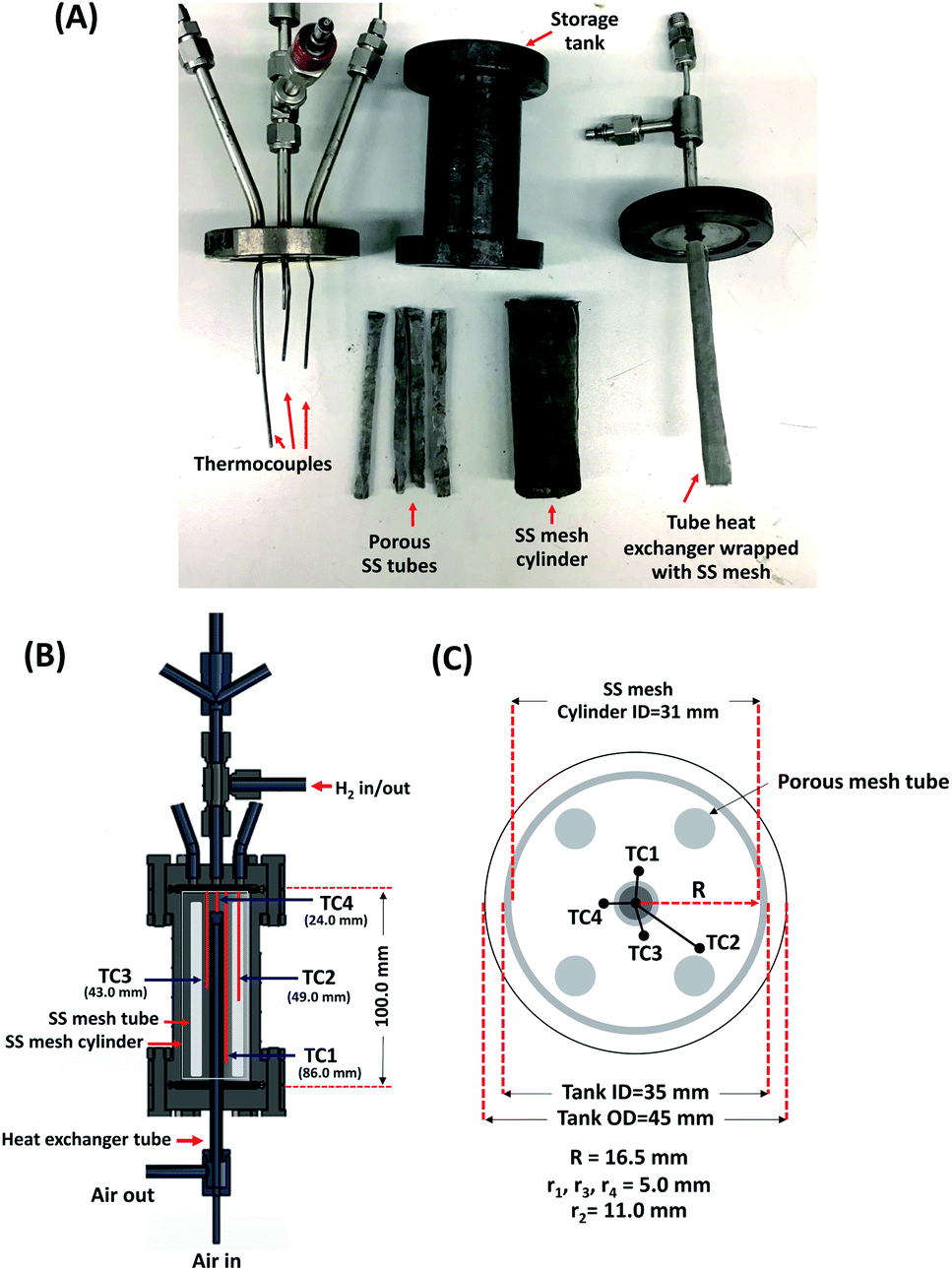
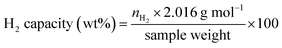
A cylindrical hydrogen storage tank (packing volume of 96.2 mL) with the components shown in Fig. 1(A) was packed with 44.7248 g of as-milled MgH2–Ni–La@TiF4–CNT.37,38 Temperature profiles during hydrogen exchange reaction were detected by K-type thermocouples (TCs, −250 to 1300 °C, SL heater) placed along the tank length (TC1, TC3, and TC4) (Fig. 1(B)). Setting temperature (Tset) during the experiments was controlled by a PID temperature controller connected to TC2 as a temperature sensor for the controller. Hydrogen diffusion in the tank was enhanced by inserting four porous stainless steel (SS) tubes (SS304, no. 120) into the powder sample (Fig. 1(A) and (C)). De/rehydrogenation were performed using a test station integrated with a controller program constructed by a LabVIEW® software.37–39 System pressures were measured by pressure transducers using an OMEGA Engineering PX409-1.5KGI and PX309-3KGI. Temperature and pressure signals detected during the experiments were collected using the module data loggers (NI USB-6009, National Instruments). As-milled MgH2–Ni–La@TiF4–CNT was hydrogenated at 250 °C under 10–15 bar H2 to obtain as-prepared MgH2–Ni–La@TiF4–CNT. Hydrogenation was carried out at isothermal condition (Tset = 250 °C) under 10–18 bar H2 and dehydrogenation was at Tset = 300 °C with the initial pressure of ∼15 bar H2, remaining after hydrogenation. Heat released during exothermic hydrogenation was removed by a double tube heat exchanger filled with 3–5 L min−1 compressed air at room temperature. Prior to the titration measurements, 14 de/rehydrogenation cycles of as-prepared MgH2–Ni–La@TiF4–CNT based tank were performed to stabilize the kinetics of hydride materials. Hydrogen desorbed content (standard L, SL) was measured using mass flow controller (MFC, 0–2 SL per min (SLM), a Bronkhorst EL-FLOW selected F-201CV) and calculated by integrating the peak area of hydrogen flow rate (SLM) versus time (min) plot. Total hydrogen storage capacity defined as the combination of remained hydrogen after absorption and material capacity was calculated as follows.
| |
 | (1) |
| |
 | (2) |
| |
 | (3) |
where
VSTP (L) and
Vs (SL) are volumes of hydrogen gas at the standard temperature and pressure condition (STP,
TSTP = 273.15 K and
PSTP = 1.0133 bar) and at the standard condition of MFC (
Ts = 294.15 K and
Ps = 1.0085 bar), respectively.
nH2 (mol) is hydrogen moles and standard molar volume is 22.4 L mol
−1.
 |
| | Fig. 1 The components of the cylindrical hydrogen storage tank (A) and the positions of thermocouples (TCs) inside the tank (B and C). | |
Results and discussion
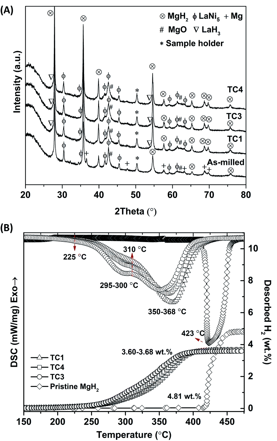
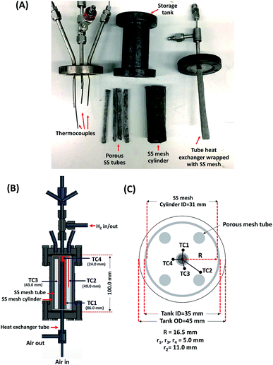
Chemical compositions of as-milled and as-prepared MgH2–Ni–La@TiF4–CNT are investigated by PXD technique. From Fig. 2(A), diffraction peaks of MgH2, LaNi5, and MgO are found in as-milled and as-prepared samples at all positions in the tank. The as-milled sample reveals a slight signal of Mg due to incomplete hydrogenation during sample preparation. All as-prepared samples show complete transformation of Mg to MgH2 (Fig. 2(A)). The formation of MgO is due to the oxidation of Mg-containing phases with air and moisture during the measurements. Slight signal of LaH3 detected in all as-prepared samples suggests the reaction of LaNi5, MgH2, and H2 to form Mg2NiH4 and LaH3.40 Considering LaNi5 content (20 wt% or ∼1.2 mol% with respect to MgH2 content), hydrogenation of Mg–Ni–La composite is represented stoichiometrically in eqn (4). The disappearance of Mg2NiH4 diffraction in Fig. 2(A) can be due to a small amount, amorphous state, and/or inhomogeneity. Furthermore, dehydrogenation patterns of pristine MgH2 and as-prepared MgH2–Ni–La@TiF4–CNT at TC1, TC3, and TC4 are investigated by H2-TPD technique. From Fig. 2(B), pristine MgH2 shows single-step dehydrogenation at onset and main temperatures at ∼415 and 423 °C, respectively, together with hydrogen capacity of 4.81 wt% H2. For as-prepared MgH2–Ni–La@TiF4–CNT samples, two-step decomposition of Mg2NiH4 and MgH2 (eqn (5) and (6), respectively) are observed. Onset and main dehydrogenations of Mg2NiH4 are found at 225 and 295–300 °C, respectively,26,29 while those of MgH2 are at higher temperatures of 310 and 350–368 °C, respectively. Comparing with pristine MgH2, onset and man dehydrogenation temperatures of MgH2 in as-prepared MgH2–Ni–La@TiF4–CNT are significantly lower (ΔT = 105 and 75 °C, respectively). This can be explained by the catalytic effects of TiF4, MWCNTs, and the combined Mg2NiH4–LaH3 on hydrogen sorption properties of MgH2.27–29 For phase transition of LaH3 to LaH2.3 at about 400 °C,26 hydrogen signal cannot be observed by H2-TPD probably due to a small amount of LaH3, corresponding PXD results (Fig. 2(A)). Hydrogen storage capacities in the range of 3.60–3.68 wt% H2 are obtained. Regarding the content of all components (MgH2 doped with 20 wt% LaNi5, 5 wt% TiF4, and 5 wt% MWCNTs) and dehydrogenation pathways (eqn (5) and (6)), theoretical hydrogen storage capacity of 5.9 wt% H2 is calculated according to eqn (7). Deficient hydrogen content detected from H2-TPD results (Fig. 2(B)) with respect to theoretical capacity is described by an incomplete reaction between LaNi5 and MgH2 to form Mg2NiH4 during sample preparation (eqn (4)), confirmed by the signal of residual LaNi5 in PXD spectra of as-prepared samples (Fig. 2(A)).| | |
0.12MgH2(s) + 0.012LaNi5(s) + 0.018H2(g) → 0.06Mg2NiH4(s) + 0.012LaH3(s)
| (4) |
| | |
0.06Mg2NiH4(s) → 0.06Mg2Ni(s) + 0.12H2
| (5) |
| | |
0.88MgH2(s) → 0.88Mg(s) + 0.88H2(g)
| (6) |
| |
 | (7) |
 |
| | Fig. 2 PXD spectra of as-milled and as-prepared MgH2–Ni–La@TiF4–CNT at different positions inside the tank (A) and H2-TPD results during dehydrogenation of as-received MgH2 and as-prepared MgH2–Ni–La@TiF4–CNT (B). | |
Comparing with MgH2–TiF4–MWCNTs based tank reported in the previous work,37 the dehydrogenation temperature of MgH2 reduces from 388 to 350–368 °C (MgH2–Ni–La@TiF4–CNT tank in this work). Moreover, significant Mg2NiH4 content (and also LaH3) at TC3 > TC4 > TC1, assured by the greater area of the first H2-TPD peak in Fig. 2(B) results in lower dehydrogenation temperature and faster kinetics of MgH2. This might be attributed to the catalytic effects of in situ formed LaH3 and Mg2NiH4 on kinetic properties of MgH2.26 Besides, it was reported that LaH3 could decrease dehydrogenation enthalpy of MgH2,28 while Mg2NiH4 acted as nucleation sites for MgH2 formation.30 Different amounts of Mg2NiH4 at TC1, TC3, and TC4 can be described by poor distribution of LaNi5 in MgH2 matrices and/or ineffective hydrogenation due to deficient heat exchange between exothermic hydrogenation and heat transfer fluid.
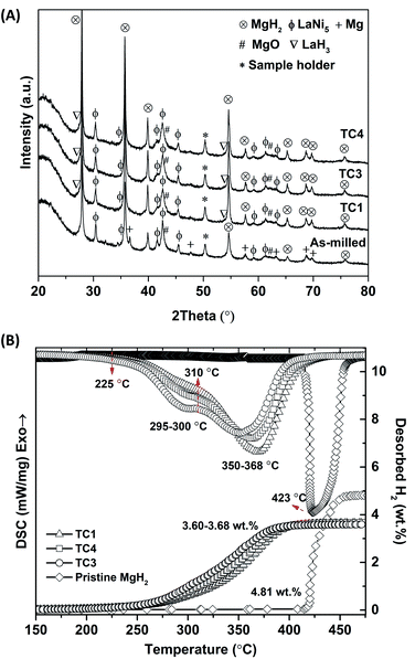
De/rehydrogenation kinetics, reversibility, and reaction pathways of MgH2–Ni–La@TiF4–CNT based tank are further studied. Prior to cycling, MgH2–Ni–La@TiF4–CNT based tank was stabilized by performing 14 de/rehydrogenation cycles. The first dehydrogenation at isothermal condition (Tset = 300 °C) under the initial pressure of 15 bar H2, remaining after absorption is carried out by releasing hydrogen through MFC with a constant flow rate of 0.3 SLM (Fig. 3(A)). Endothermic dehydrogenation starts at t ∼ 6 min under system pressure (Psys) of 3.5 bar H2. Two-step decomposition of Mg2NiH4 and MgH2, in accordance with H2-TPD results of as-prepared samples (Fig. 2(B)) is observed at equilibrium temperatures (Teq) of 290–307 and 290–300 °C, respectively. These Teq are in accordance with equilibrium pressure (Peq) of ∼2.5–4 and ∼1.3–1.8 bar H2 for Mg2NiH4 and MgH2, respectively.40,41 The greater Peq than Psys (1.9–2.4 and 1.1 bar H2 for Mg2NiH4 and MgH2, respectively) (Fig. 3(A)) encourages dehydrogenation of hydride materials, confirmed by continuous hydrogen release and endothermic event at all positions in the tank. Significant endothermic desorption at TC3 and TC4 revealed as considerable temperature reduction (ΔT = 20–25 and 22–30 °C for the decomposition of Mg2NiH4 and MgH2, respectively) and long plateau range suggest effective dehydrogenation. This can be due to the greater amount of Mg2NiH4 (and also LaH3) formed at TC3 and TC4, corresponding to H2-TPD results (Fig. 2(B)). Moreover, effective heat supply from the external heater at the middle position of the tank (TC3) shown as the highest initial temperature (Tin = 320 °C) favours desorption kinetics. For TC4, although Tin is lower (312 °C), the position adjacent to hydrogen inlet and outlet possibly benefits hydrogen release from the tank and also desorption kinetics. Hydrogen flow rate of 0.3 SLM is continuously obtained for 21 min and gradually decreases until dehydrogenation completes at t = 150 min, in accordance with the increase of temperatures at all TCs to the initial values.
 |
| | Fig. 3 Temperature, pressure, and mass flow rate signals during dehydrogenation (Tset = 300 °C) (A) and rehydrogenation (Tset = 250 °C and P(H2) = 10–18 bar) (B) of MgH2–Ni–La@TiF4–CNT based tank. | |
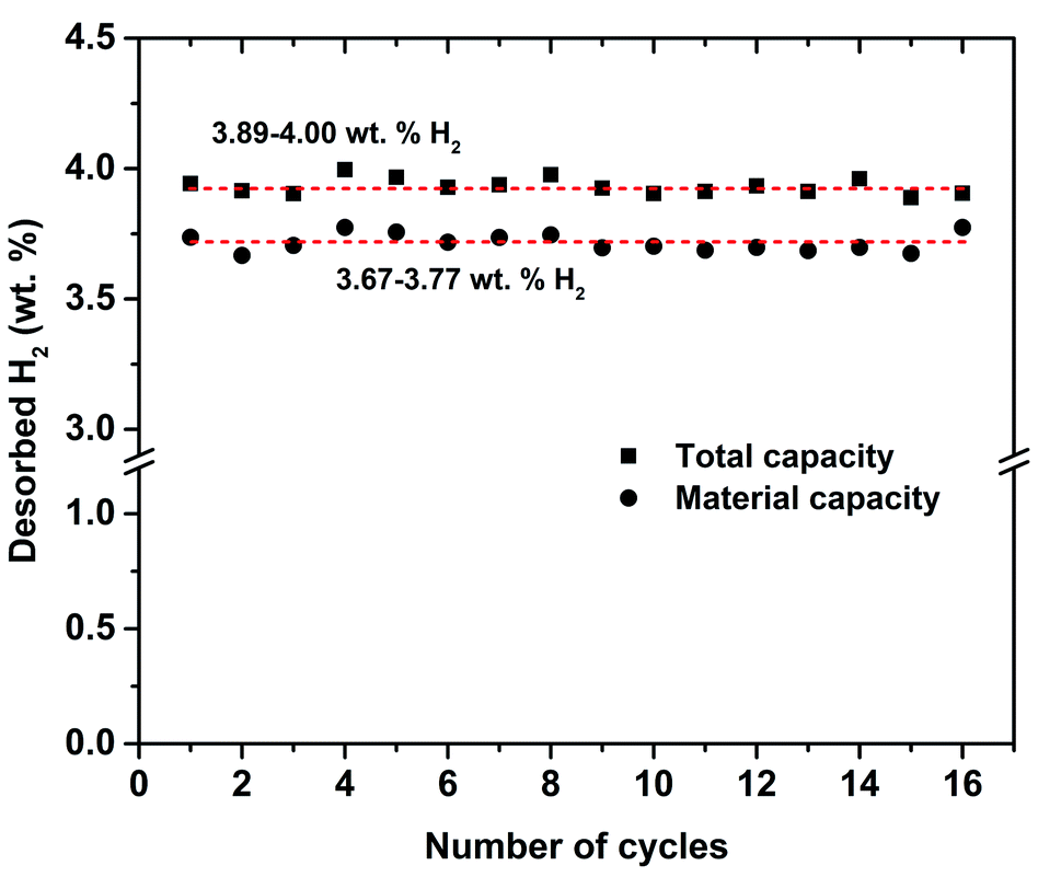
Total hydrogen content and storage capacity are 21.00 SL and 3.90 wt% H2, respectively (Fig. 3(A)). By subtracting with hydrogen content remaining after hydrogenation (1.10 SL and ∼0.20 wt% H2), the material storage capacity of MgH2–Ni–La@TiF4–CNT based tank is 3.70 wt% H2, approaching to hydrogen content detected in H2-TPD results (Fig. 2(B)). Furthermore, rehydrogenation is continued at isothermal condition (Tset = 250 °C) under Psys of 10–18 bar H2 with compressed airflow of 3–5 L min−1 (Tair-in = 24 °C) as heat transfer fluid (Fig. 3(B)). Comparable Tin at all positions (251–258 °C) indicates good thermal conductivity in the tank achieved from addition of MWCNTs.20 By applying hydrogen to the tank, all temperatures increase rapidly to Teq of 365–383 °C owing to fast exothermic absorption (Fig. 3(B)). These Teq are in agreement with Peq of ∼10–14 and 10–20 bar H2 for MgH2 and Mg2NiH4, respectively.41,42 Comparable Peq with Psys implies superior hydrogen diffusion inside the tank during hydrogenation. This can be benefited by the insertion of porous SS tubes in the powder sample (Fig. 1(C)). The enhanced temperature of compressed air from 24 to 99 °C indicates effective heat transport from the exothermic hydrogenation to heat transfer fluid. Complete hydrogenation assured by temperature reduction to initial values at all positions is within 16 min (Fig. 3(B)). Comparing to the previous work of MgH2–TiF4–MWCNTs tank with comparable sample mass (∼45 g),20 hydrogen desorption and absorption times reduce from 200 and 40 min, respectively, to 150 and 16 min, respectively (MgH2–Ni–La@TiF4–CNT tank in this study). It should be noted that hydrogenation with short plateau range is found at both ends of the tank (TC1 and TC4), while that at the middle position (TC3) reveals longer plateau temperature (Fig. 3(B)). The short plateau range hints at either fast kinetics or ineffective hydrogenation. Considering the high Mg2NiH4 content found at TC4 (H2-TPD curves and dehydrogenation profiles in Fig. 2(B) and 3(A), respectively), its short plateau temperature indicates fast and effective hydrogenation, whereas that at TC1 (low Mg2NiH4 content) is most likely due to poor kinetics. Superior kinetics at TC4 might be explained by the fact that it is the first position, where the cold compressed air is in contact with the heat from the exothermic hydrogenation. However, reaction heat accumulated in the heat transfer fluid at TC3 and TC1 probably lead to reduced hydrogenation efficiency. Furthermore, cycling stability and effective reversibility of MgH2–Ni–La@TiF4–CNT based tank are revealed by the comparable total and material capacities of 3.89–4.00 and 3.67–3.77 wt% H2, respectively (up to 68 and 64% of theoretical value, respectively) upon 16 de/rehydrogenation cycles (Fig. 4). Considering MgH2 doped with 1.5 mol% LaNi5 approaching to LaNi5 content used in our work (1.2 mol%), hydrogen capacity up to 3.5 wt% H2 was obtained from this Mg–Ni–La composite in the laboratory scale.26 De/rehydrogenation performances and reversibility of hydride materials are usually deficient after upscaling due to poor thermal conductivity and hydrogen diffusion inside the hydride beds. However, greater material hydrogen capacities (3.67–3.77 wt% H2) of MgH2–Ni–La@TiF4–CNT based tank than that of MgH2 doped with 1.5 mol% LaNi5 (3.5 wt% H2) are observed and maintained upon cycling. This can be explained by catalytic effects and the enhanced thermal conductivity and hydrogen diffusion obtained after doping with TiF4 and MWCNTs.
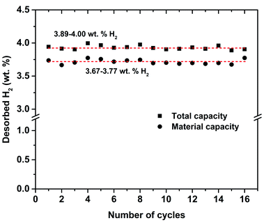 |
| | Fig. 4 Total and material hydrogen storage capacities of MgH2–Ni–La@TiF4–CNT based tank upon 16 de/rehydrogenation cycles. | |
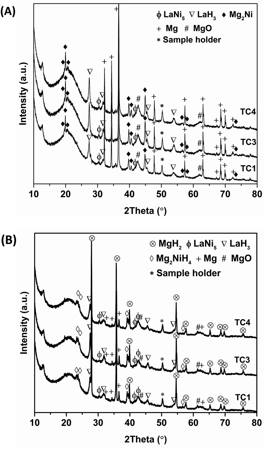
Furthermore, the reaction mechanisms during cycling at different positions inside the tank are characterized by PXD technique. To avoid interrupting the cycling measurements and due to comparable performances upon cycling, the de/rehydrogenated samples after the 16th cycles are collected for characterizations. From Fig. 5(A), comparable phases of Mg2Ni, Mg, LaH3, LaNi5, and MgO are found in dehydrogenated samples at all positions. The formation of Mg2Ni and Mg hints at successful dehydrogenation of Mg2NiH4 and MgH2 (eqn (5) and (6)), while the thermally stable phase of LaH3 does not decompose due to low operating temperature during dehydrogenation (Tset = 300 °C). The signal of LaNi5 suggests the incomplete formation of Mg2NiH4 (eqn (4)) during sample preparation. In the case of hydrogenation, all hydrogenated samples show diffraction peaks of MgH2, Mg2NiH4, LaH3, LaNi5, Mg, and MgO (Fig. 5(B)). The formation of MgH2 and Mg2NiH4 implies successful rehydrogenation of Mg and Mg2Ni, respectively (reverse reaction of eqn (5) and (6)). The unreacted LaNi5 and Mg found upon cycling are responsible for deficient hydrogen released and reproduced to the theoretical capacity (5.9 wt% H2) (Fig. 4). Moreover, the morphology of the samples at as-prepared state and after cycling are investigated by SEM technique. Comparable morphology and various particle sizes in micrometer range are discovered in as-prepared samples at all positions (Fig. 6(A)). For the samples after cycling, finer powder with smaller particle size as compared with as-prepared samples are detected (Fig. 6(B)). This can be described by effective de/rehydrogenation upon cycling due to significant hydrogen diffusion in hydride beds inside the tank. Nevertheless, particle agglomeration partially found in the sample at TC1 (a red circle in Fig. 6(B)) suggests less effective hydrogen de/absorption, corresponding to H2-TPD results and de/rehydrogenation profiles (Fig. 2(B) and 3).
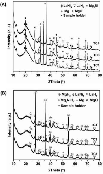 |
| | Fig. 5 PXD spectra of dehydrogenated (A) and rehydrogenated (B) samples after 16 de/rehydrogenation cycles at different positions inside the tank. | |
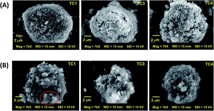 |
| | Fig. 6 SEM images of as-prepared (A) and the 16th rehydrogenated (B) samples at different positions inside the tank. | |
Conclusions
Kinetic properties, cycling efficiency, and reaction pathways of Mg–Ni–La based small hydrogen storage tank doped with TiF4 and MWCNTs were investigated. During sample preparation, MgH2 reacted with LaNi5 and H2 to form Mg2NiH4 and LaH3. Onset and main decompositions of Mg2NiH4 were found at 225 and 295–300 °C, respectively, while those of MgH2 were at 310 and 350–368 °C, respectively. Dehydrogenation kinetics at the middle and hydrogen inlet/outlet positions was enhanced due to sufficient heat supplied from the external heater and fast hydrogen release from the tank. Superior hydrogen diffusion at all positions in the tank was confirmed by comparable applied pressure with equilibrium pressure. Hydrogenation performances relied on the effectiveness of heat transfer from exothermic reaction to heat transfer fluid. Fast hydrogenation kinetics was found at the hydrogen inlet/outlet position, where the heat transfer fluid was firstly in contact with reaction heat. Total and material hydrogen capacities upon 16 de/rehydrogenation cycles were averagely in the ranges of 3.89–4.00 and 3.67–3.77 wt% H2, respectively. Due to good hydrogen diffusion inside the tank, effective de/rehydrogenation cycles were obtained and revealed as the powder sample with finer and smaller particles after cycling. However, partial particle agglomeration was found at the position with poor performances.
Conflicts of interest
There are no conflicts to declare.
Acknowledgements
The authors would like to acknowledge The Thailand Research Fund and Suranaree University of Technology (TRF Research Career Development: RSA6280037), The Royal Golden Jubilee PhD program (PHD/0183/2559), for financial support. This work has been partially supported by the Research Network NANOTEC (RNN) program of the National Nanotechnology Center (NANOTEC), NSTDA, Ministry of Higher Education, Science, Research and Innovation (MHESI), Thailand.
References
- G. Liang, J. Alloys Compd., 2004, 370, 123–128 CrossRef CAS.
- M. Dornheim, S. Doppiu, G. Barkhordarian, U. Boesenberg, T. Klassen, O. Gutfleisch and R. Bormann, Scr. Mater., 2007, 56, 841–846 CrossRef CAS.
- L. Schlapbach and A. Züttel, Nature, 2001, 414, 353–358 CrossRef CAS.
- I. P. Jain, C. Lal and A. Jain, Int. J. Hydrogen Energy, 2010, 35, 5133–5144 CrossRef CAS.
- T. Sadhasivam, H. T. Kim, S. Jung, S. H. Roh, J. H. Park and H. Y. Jung, Renew. Sustain. Energy Rev., 2017, 72, 523–534 CrossRef CAS.
- Z. Cao, L. Ouyang, Y. Wu, H. Wang, J. Liu, F. Fang, D. Sun, Q. Zhang and M. Zhu, J. Alloys Compd., 2015, 623, 354–358 CrossRef CAS.
- L. Z. Ouyang, Z. J. Cao, H. Wang, J. W. Liu, D. L. Sun, Q. A. Zhang and M. Zhu, Int. J. Hydrogen Energy, 2013, 38, 8881–8887 CrossRef CAS.
- Y. Lu, H. Wang, J. Liu, L. Ouyang and M. Zhu, J. Power Sources, 2018, 396, 796–802 CrossRef CAS.
- L. Z. Ouyang, Z. J. Cao, H. Wang, J. W. Liu, D. L. Sun, Q. A. Zhang and M. Zhu, J. Alloys Compd., 2014, 586, 113–117 CrossRef CAS.
- G. Liang, J. Huot, S. Boily, A. Van Neste and R. Schulz, J. Alloys Compd., 1999, 292, 247–252 CrossRef CAS.
- G. Barkhordarian, T. Klassen and R. Bormann, J. Phys. Chem. B, 2006, 110, 11020–11024 CrossRef CAS.
- N. N. Sulaiman, N. Juahir, N. S. Mustafa, F. A. Halim Yap and M. Ismail, J. Energy Chem., 2016, 25, 832–839 CrossRef.
- J. W. Kim, J. P. Ahn, S. A. Jin, S. H. Lee, H. S. Chung, J. H. Shim, Y. W. Cho and K. H. Oh, J. Power Sources, 2008, 178, 373–378 CrossRef CAS.
- Q. Zhang, L. Zang, Y. Huang, P. Gao, L. Jiao, H. Yuan and Y. Wang, Int. J. Hydrogen Energy, 2017, 42, 24247–24255 CrossRef CAS.
- Y. Wang, Q. Zhang, Y. Wang, L. Jiao and H. Yuan, J. Alloys Compd., 2015, 645, S509–S512 CrossRef CAS.
- L. Zhang, L. Ji, Z. Yao, N. Yan, Z. Sun, X. Yang, X. Zhu, S. Hu and L. Chen, Int. J. Hydrogen Energy, 2019, 44, 21955–21964 CrossRef CAS.
- M. S. El-Eskandarany, H. Al-Matrouk, M. Behbehani, E. Shaban, A. Alkandary, F. Aldakheel and M. Al-Saidi, Mater. Chem. Phys., 2018, 203, 17–26 CrossRef CAS.
- X. Zhang, Z. Leng, M. Gao, J. Hu, F. Du, J. Yao, H. Pan and Y. Liu, J. Power Sources, 2018, 398, 183–192 CrossRef CAS.
- J. Liu, Y. Liu, Z. Liu, Z. Ma, Y. Ding, Y. Zhu, Y. Zhang, J. Zhang and L. Li, J. Alloys Compd., 2019, 789, 768–776 CrossRef CAS.
- M. S. Yahya and M. Ismail, J. Energy Chem., 2019, 28, 46–53 CrossRef.
- N. S. Mustafa and M. Ismail, J. Alloys Compd., 2017, 695, 2532–2538 CrossRef CAS.
- M. S. Yahya, N. N. Sulaiman, N. S. Mustafa, F. A. Halim Yap and M. Ismail, Int. J. Hydrogen Energy, 2018, 43, 14532–14540 CrossRef CAS.
- L. shuai XIE, J. shan LI, T. bang ZHANG and H. chao KOU, Trans. Nonferrous Met. Soc. China, 2017, 27, 569–577 CrossRef.
- L. Xie, Y. Liu, X. Zhang, J. Qu, Y. Wang and X. Li, J. Alloys Compd., 2009, 482, 388–392 CrossRef CAS.
- T. Spassov, P. Delchev, P. Madjarov, M. Spassova and T. Himitliiska, J. Alloys Compd., 2010, 495, 149–153 CrossRef CAS.
- J. J. Márquez, D. R. Leiva, R. Floriano, J. Soyama, W. B. Silva, T. T. Ishikawa, C. S. Kiminami and W. J. Botta, Int. J. Hydrogen Energy, 2018, 43, 13348–13355 CrossRef.
- G. Liang, J. Huot, S. Boily, A. Van Neste and R. Schulz, J. Alloys Compd., 2000, 297, 261–265 CrossRef CAS.
- X. Zhu, L. Pei, Z. Zhao, B. Liu, S. Han and R. Wang, J. Alloys Compd., 2013, 577, 64–69 CrossRef CAS.
- A. Zaluska, L. Zaluski and J. O. Ström-Olsen, J. Alloys Compd., 1999, 289, 197–206 CrossRef CAS.
- T. Liu, C. Wang and Y. Wu, Int. J. Hydrogen Energy, 2014, 39, 14262–14274 CrossRef CAS.
- F. Guo, T. Zhang, L. Shi and L. Song, Int. J. Hydrogen Energy, 2019, 44, 16745–16756 CrossRef CAS.
- M. A. Lillo-Ródenas, Z. X. Guo, K. F. Aguey-Zinsou, D. Cazorla-Amorós and A. Linares-Solano, Carbon, 2008, 46, 126–137 CrossRef.
- A. Chaise, P. de Rango, P. Marty, D. Fruchart, S. Miraglia, R. Olivès and S. Garrier, Int. J. Hydrogen Energy, 2009, 34, 8589–8596 CrossRef CAS.
- J. Zhang, X. F. Yu, C. Mao, C. G. Long, J. Chen and D. W. Zhou, Energy, 2015, 89, 957–964 CrossRef CAS.
- S. Thiangviriya and R. Utke, Int. J. Hydrogen Energy, 2016, 41, 2797–2806 CrossRef CAS.
- P. Plerdsranoy and R. Utke, Int. J. Hydrogen Energy, 2015, 40, 7083–7092 CrossRef CAS.
- S. Thiangviriya, P. Plerdsranoy, C. Sitthiwet, P. Dansirima, P. Thongtan, P. Eiamlamai, O. Utke and R. Utke, Int. J. Hydrogen Energy, 2019, 44, 20173–20182 CrossRef CAS.
- P. Thongtan, P. Dansirima, S. Thiangviriya, N. Thaweelap, A. Suthummapiwat, P. Plerdsranoy and R. Utke, Int. J. Hydrogen Energy, 2018, 43, 12260–12270 CrossRef CAS.
- P. Dansirima, S. Thiangviriya, P. Plerdsranoy, O. Utke and R. Utke, Int. J. Hydrogen Energy, 2019, 44, 10752–10762 CrossRef CAS.
- T. Liu, C. Chen, C. Qin and X. Li, Int. J. Hydrogen Energy, 2014, 39, 18273–18279 CrossRef CAS.
- X. X. Zeng, Y. T. Xu, Y. X. Yin, X. W. Wu, J. Yue and Y. G. Guo, Mater. Today Nano, 2019, 8, 100057 CrossRef.
- J. J. Vajo, W. Li and P. Liu, Chem. Commun., 2010, 46, 6687–6689 RSC.
|
| This journal is © The Royal Society of Chemistry 2020 |
Click here to see how this site uses Cookies. View our privacy policy here. 
 Open Access Article
 This Open Access Article is licensed under a Creative Commons Attribution-Non Commercial 3.0 Unported Licence
 ac,
Oliver Utked and
Rapee Utke
ac,
Oliver Utked and
Rapee Utke