 Open Access Article
Investigation on the mechanical properties and fracture phenomenon of silicon doped graphene by molecular dynamics simulation†
Md. Habibur Rahman *,
Shailee Mitra,
Mohammad Motalab and
Pritom Bose
Department of Mechanical Engineering, Bangladesh University of Engineering and Technology, Dhaka-1000, Bangladesh. E-mail: imd.habiburrahman@gmail.com
First published on 25th August 2020
Abstract
Silicon doping is an effective way to modulate the bandgap of graphene that might open the door for graphene to the semiconductor industries. However, the mechanical properties of silicon doped graphene (SiG) also plays an important role to realize its full potential application in the electronics industry. Electronic and optical properties of silicon doped graphene are well studied, but, our understanding of mechanical and fracture properties of the doped structure is still in its infancy. In this study, molecular dynamics (MD) simulations are conducted to investigate the tensile properties of SiG by varying the concentration of silicon. It is found that as the concentration of silicon increases, both fracture stress and strain of graphene reduces substantially. Our MD results also suggest that only 5% of silicon doping can reduce the Young's modulus of graphene by ∼15.5% along the armchair direction and ∼13.5% along the zigzag direction. Tensile properties of silicon doped graphene have been compared with boron and nitrogen doped graphene. The effect of temperature, defects and crack length on the stress–strain behavior of SiG has also been investigated. Temperature studies reveal that SiG is less sensitive to temperature compared to free stranding graphene, additionally, increasing temperature causes deterioration of both fracture stress and strain of SiG. Both defects and cracks reduce the fracture stress and fracture strain of SiG remarkably, but the sensitivity to defects and cracks for SiG is larger compared to graphene. Fracture toughness of pre-cracked SiG has been investigated and results from MD simulations are compared with Griffith's theory. It has been found that for nano-cracks, SiG with larger crack length deviates more from Griffith's criterion and the degree of deviation is larger compared to graphene. Fracture phenomenon of pre-cracked SiG and the effect of strain rate on the tensile properties of SiG have been reported as well. These results will aid the design of SiG based semiconducting nanodevices.
1. Introduction
Two dimensional (2D) materials such as graphene, silicene, hBN, germanene and stanene exhibit interesting electronic, mechanical and thermal properties.1–7 Among them, graphene stands out because of its remarkable mechanical, electrical, thermal and other physical properties.8–10 Graphene has already been successfully deployed in electronic sensors, solar cells, transistors, batteries, capacitors, composites and in many other fields.11–14 Different experimental and numerical simulations have been conducted to investigate the physical properties (i.e., mechanical, electrical and thermal) of graphene.15–19 Semiconductor application of graphene becomes limited due to its semimetal nature, viz., zero intrinsic bandgap in graphene due to the Dirac like band structure.20 Several experimental and numerical approaches have been conducted to open and extract a useful bandgap in graphene and to modulate the electronic properties.21–31 The literature reveals that BN co-doping, encapsulating with hydrogen and fluorine functionalized hBN, aluminium, phosphorous, sulphur and silicon doping are a few chemical and physio-adsorbing methods to open a useful bandgap of graphene. Hu et al. reported DFT calculations for the bandgap opening of bilayer graphene by single and double molecular doping.29Using first-principles calculation, Tang et al. investigated tunable bandgap of graphene on functionalized hexagonal boron nitride with hydrogen and fluorine.27 They demonstrated that hydrogenation and fluorination on the boron-nitride substrate could remarkably alter the electronic properties of graphene. Their studies show that a finite 79 meV bandgap in graphene is opened and can be effectively modulated by adjusting the spacing of the interlayer, increasing the number of boron nitride layers and also adding an external electrical field. In addition, they also concluded that graphene on modified hexagonal boron-nitride with a tunable bandgap may provide an effective way for fabricating high-performance graphene-based nanodevices.27 Besides, Fan et al. stated that bandgap of graphene could be effectively opened by adding small boron and nitrogen into the graphene domain.21 They found that a small bandgap in the Dirac points could be opened by random doping with boron or nitrogen without modulating the Fermi level.21 Houmad et al.22 investigated the underlying mechanism that could open the bandgap of graphene through silicon doping. They measured the bandgap of graphene with and without silicon doping, showing that silicon doping opens the bandgap of graphene, and improves its optical conductivity.22 They stated that silicon-doped graphene could be used effectively in solar cell application.22
Zhang et al. synthesized a monolayer of silicon-doped graphene (SiG) with a wide surface area using a SiH4 flow in a chemical vapor deposition (CVD) chamber.32 Measurements of Raman and X-ray photoelectron spectroscopy show that the silicon atoms are doped into graphene lattice at a doping level of 2.7–4.5% and electrical measurements based on a field-effect transistor demonstrate that a useful bandgap was opened with the aid of silicon doping. Most notably, the opening of a bandgap can be accomplished without a significant deterioration in carrier mobility as well as the work function of monolayer SiG.32 This makes silicon doping an important technique for engineering the bandgap of monolayer graphene.32
Some literature has reported silicon doped graphene (SiG) as a promising metal-free catalyst for N2O, SO2, CO reduction and green energy as well.33–38 Chen et al. stated that silicon-doped graphene can be an ideal NO, NO2 detection sensor, and N2O reduction metal-free catalyst. Their research showed that while adsorption of these molecules on pristine graphene is very weak, silicon doping increases the interaction of these molecules (nitrogen and oxygen) in different ways with graphene.34 Esrafili et al. stated that silicon doped graphene could serve as a low-cost and effective metal-free catalyst for an oxidation reaction to SO2.36 Mortazavi et al.39 performed molecular dynamics (MD) simulation on the thermal conductivity and the tensile properties of boron-doped graphene. They stated that Young's modulus and fracture strength of graphene could be decreased by approximately 5% and 8%, respectively by only 4% boron doping.39 Another literature by Mortazavi et al. documented the tensile mechanical response of nitrogen-doped graphene using molecular dynamics (MD) simulation,40 where they demonstrated that the fracture stress of graphene could be decreased by more than 35% by having only 2% of the nitrogen atoms.40
However, issues like temperature-dependent tensile properties, defects, crack and fracture phenomenon, are elusive within the potential use of monolayer SiG in terms of percentage of silicon. The mechanical properties such as fracture stress, fracture strain in terms of temperature, defects, crack length and strain rate of monolayer SiG are important to investigate extensively both in theory and experiment for ensuring performance reliability, mechanical endurance and the life-time of SiG based nanodevices. Therefore, the current work aims to investigate the mechanical properties of monolayer SiG. At first, the effects of silicon concentrations on the fracture stress and strain of graphene have been reported. Next, temperature studies have also been carried out to explore the thermo-mechanical properties of SiG at various temperature. Defects and crack play an important role which dictates the tensile properties of materials under loading condition, keeping this in mind, the authors of this article have also documented the effect of vacancy defect concentrations, crack length as well as strain rate on the tensile properties of SiG. Finally, the fracture phenomenon of pre-cracked SiG has been explored.
2. Computational method
In this investigation, molecular dynamics simulations have been performed using the Large-scale Atomic/Molecular Massively Parallel Simulator (LAMMPS)41 package for calculating the tensile properties of SiG. To define the interatomic interactions between C–C, Si–Si and C–Si atoms in the MD calculation, modified Tersoff potential has been utilized.42–44 Atomistic visualization is done with the aid of OVITO.45 For our study, we have used a structure of 30 nm × 30 nm SiG containing different percentage of carbon and silicon atoms. Carbon atoms are replaced by silicon atoms randomly with required percentage with the aid of atomsk.46Fig. 1 shows graphene doped with 2% silicon atoms. For investigating mono vacancy, different percentage of carbon atoms are removed from SiG. To generate a crack, a line of atoms are removed from the center of SiG with different lengths. The thickness of SiG nanosheet has been assumed to be 0.335 nm.10 During the simulation process, periodic boundary conditions have been applied along the X, Y and Z axis, maintaining a 5 nm gap in the simulation box along the Z-axis to suppress the interaction between the SiG and its periodic image.3,47 The equations of motion are solved numerically with a time step of 1 fs using the Velocity Verlet algorithm.47 At first, the energy of the system is minimized with the aid of the Conjugate Gradient (CG) minimization scheme.48 Further NVE, NPT and NVT equilibration are performed for 50 ps, 60 ps and 20 ps, respectively.48 Appropriate convergence of the potential energy and target thermodynamic variables are ensured in each of the relaxation steps. Finally, the uniaxial tensile load is applied along with armchair and zigzag direction. Three different strain rate such as 108 s−1,109 s−1 and 1010 s−1 have been used in this study with infrequent thermo-stating.48 It is worth to mention that these high strain rates are routinely used in the typical atomistic simulations.6,10,48 The atomic stress in our simulation is calculated using Virial stress theorem48 (Readers are referred to the ESI† file of this article). Note that for each simulation three samples with the different initial condition (i.e., molecular velocity) have been taken and corresponding errors induced from the temperature fluctuation during MD simulation have been added to the results.
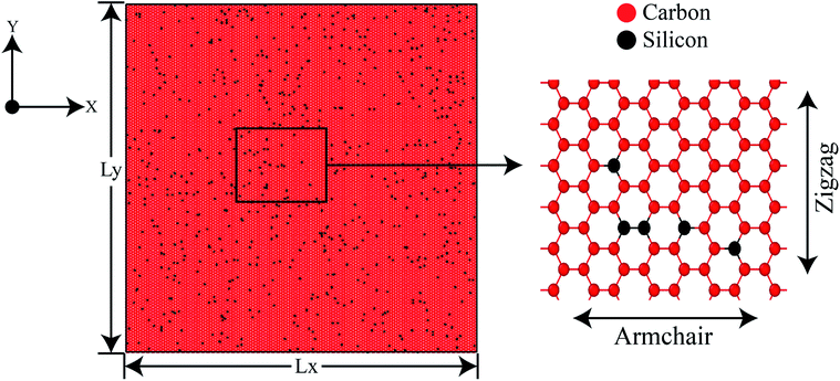 | ||
| Fig. 1 Initial coordinates of 30 nm × 30 nm 2% silicon-doped graphene (2% SiG) with a magnified view showing both armchair and zigzag direction. | ||
To establish the validity of our computational approach and the interatomic potential function, Young's modulus of graphene is compared with published literature at 300 K temperature (Table 1).
To further validate the interatomic potential function, the bond length of C–Si after the relaxation of the SiG has been calculated as ∼0.172 nm at 100 K which is in good agreement with the literature (0.179 nm).51 The bond length of C–C after the relaxation of SiG at 100 K has been calculated as ∼0.141 nm which is also in good agreement with the literature.10
3. Results and discussions
3.1 Stress–strain behavior of graphene in terms of concentration of silicon
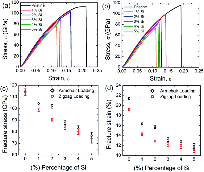
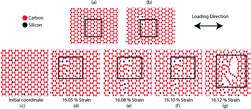
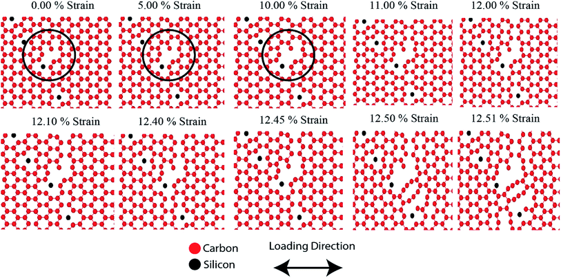
Fig. 2(a) and (b) represent the stress–strain curve of SiG for different percentage of silicon for armchair and zigzag direction, respectively at 300 K considering a strain rate of 109 (s−1). The concentration of silicon in graphene is varied from 1 to 5% and then corresponding stress–strain response of SiG is recorded. At lower strain, stress–strain relation is linear and then stress rises nonlinearly with strain up to its peak point called ultimate tensile stress and after that, material catastrophically fails and exhibits brittle failure which is analogous to other 2D materials such as graphene,10 stanene,2,20 silicene,10 and germanene.3 It is worth to mention that even after doping graphene with silicon atoms, the stress–strain curve demonstrates brittle fracture (i.e., no flow stress is observed). Another observation is that the mechanical properties of SiG maintain the characteristic anisotropies of planar honeycomb structures. The properties in the armchair and zigzag directions are considerably different due to the bond angle and bond orientation with respect to the applied loading. It is also evident from the stress–strain graph that the area under the stress–strain curves shows a gradual decay with increasing concentration of silicon. Hence, the total energy density absorbed by the material up to fracture, viz., fracture toughness decreases with the increasing concentration of silicon doping in graphene.Fig. 2(c) and (d) display the variation of fracture stress and fracture strain with varying percentage of silicon. It has been observed that as the concentration of silicon increases, both fracture stress and fracture strain decreases gradually. Our MD simulation results suggest that only 5% silicon doping on graphene reduces the fracture stress and strain by ∼31.5% and ∼44.13%, respectively for armchair loading, ∼37.5% and ∼42.5% for zigzag loading. Thus the mechanical properties of graphene deteriorate substantially as the concentration of silicon in graphene has been increased. The reason may be attributed to the reduced bond strength, local bond rotation, out of plane deformation and void formation due to silicon doping (Fig. 3).
The bond energy of C–C (346 kJ mol−1) is larger than C–Si (318 kJ mol−1) bond and so, it requires lower strain to break the C–Si bond compared to C–C bond.52–55 In the case of 5% SiG, there is a significant amount of C–Si bond present, so it has the lowest fracture stress and strain.55 Additionally, when we doped silicon in graphene, this process leads to the bond rotation, out of plane deformation of graphene lattice, which changes the atomic arrangements of graphene. It may be attributed to an electron impact of silicon on its adjacent carbon atoms and atomic size of silicon compared to carbon.55,56 This bond rotation and atomic rearrangements of graphene after silicon doping cause a lattice distortion, which results in lower fracture stress and strain of SiG compared to graphene which has been profoundly illustrated in Fig. 3. Besides an initial void is formed in the place where the concentration of silicon is maximum. Shortly after the creation of the first gap, further debonding occurs among the closest pair of atoms as the strain continues to increase. Finally, the coalescence of the voids results in the specimen being fully ruptured (Fig. 3).39,40 Thus it can be said that SiG nucleates fracture where we have the highest concentration of silicon atoms in the graphene domain. It is also evident from Fig. 2(c) and (d) that mechanical properties of graphene deteriorate, irrespective of chirality, as we increase the concentration of silicon in graphene. At higher doping concentration, graphene lattice is highly distorted and out of plane deformation occurs. So, failure nucleation is now dictated by the degree of lattice distortion caused by an enhanced amount of silicon sites and directional dependency of mechanical properties slowly diminishes.
In the present investigation, Young's modulus was calculated by fitting the curve using linear regression on the initial linear portion (strain value within 2% to 3%) of the stress–strain curve. Fig. 4 suggests a strong inverse relationship of Young's modulus with the percentage of silicon doping in graphene. As the concentration of silicon increases, a large number of C–Si bond is constructed as well as lattice distortion occurs which raises instability in graphene thus reduces the tensile strength of graphene. A lower value of stress is, therefore, required to cause the same amount of deformation which results in lowering the value of Young's modulus as the concentration of silicon increases. Besides it has been found that only 5% silicon reduces Young's modulus of graphene by ∼15.5% for armchair direction and ∼13.5% for zigzag direction. Chirality effect on Young's modulus of graphene deteriorates as we increase the concentration of silicon which is evident from Fig. 4 and the reason is discussed earlier. As the concentration of silicon increases, lattice distortion as well as void in graphene increases which deteriorates directional dependency of the mechanical properties of graphene.
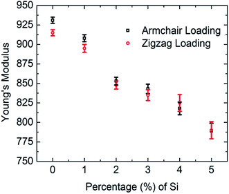 | ||
| Fig. 4 Variations of Young's modulus of graphene with silicon concentration for both armchair and zigzag loading at 300 K. | ||
Previously Mortazavi et al. reported that in the case of 4% boron-doped graphene, Young's modulus and fracture stress is reduced by ∼5% and ∼8%, respectively.39 They demonstrated that boron atoms as a doping element have a negligible effect on the mechanical properties of graphene.39 Despite lattice distortion caused by doping with boron atom, the bond energy of C–B is (356 kJ mol−1) larger than C–C bond (346 kJ mol−1).52–55 Thus the lattice distortion effect is neutralized by high C–B bond energy. That's why boron doping doesn't affect the mechanical properties of graphene considerably. Comparing our MD simulations results with Mortazavi et al. it can be inferred that the mechanical properties of graphene are more sensitive to silicon doping compared to boron doping. Another investigation was done by Mortazavi et al. in the case of nitrogen-doped graphene, suggests that Young's modulus of graphene doesn't considerably change for nitrogen concentration up to 6% but only 2% nitrogen atom reduces the fracture strength of graphene by more than ∼35%.40 This is because the bond energy of C–N (305 kJ mol−1) is smaller than C–C (346 kJ mol−1) bond.52–55,57 Therefore, it requires a lower tensile strain to break the C–N bond compared to the C–C bond. So the fracture stress of graphene is more sensitive to nitrogen doping compared to silicon but Young's modulus of graphene is more sensitive to silicon doping than nitrogen.
Based on our MD simulation, in terms of tensile strength, SiG is still better than silicene,10,58 germanene,3 stanene,2,20 bilayer germanene,6 phosphorene,59 MoS260,61 and borophene.62 Besides, SiG (1–2% silicon) is the material which has physical strength similar to hBN.10,47
Next, we considered 2% SiG to understand the effect of temperature, defects, crack length, strain rate, fracture toughness on the tensile mechanical properties and fracture phenomenon of pre-cracked SiG. Note that for reporting the effect of temperature, defects, crack length, fracture toughness on the tensile properties of SiG, a strain rate of 109 (s−1) has been considered.
3.2 Effect of temperature on the stress–strain behavior of SiG
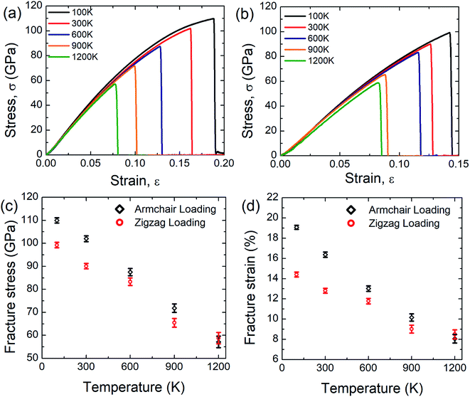
Fig. 5(a) and (b) display the stress–strain response of SiG nanosheet at different temperatures for both armchair and zigzag loading respectively. Simulations have been performed at 5 different temperature such as 100, 300, 600, 900 and 1200 Kelvin. It can be seen that as temperature increases area under the stress–strain curve that is fracture toughness of SiG decreases monotonically. It is worth to mention that there is no brittle to ductile transition temperature has been found within this temperature regime. So it can be said that SiG exhibits brittle type failure in extremely high temperature which is analogous to other 2D materials such as graphene,63 and hBN.5The results of the stress–strain response are translated into Fig. 5(c) and (d) which represent the variations of fracture stress and strain for both armchair and zigzag loading with varying temperature. It can be seen from these graphs that as temperature increases, both fracture stress and strain decreases thus showing an inverse relationship with temperature. This is because C–C, C–Si and Si–Si bonds experience higher thermal fluctuation and vibration at a higher temperature. This causes an increased mean distance between atoms, resulting from high atomic kinetic energy and mobility3,6,48 which reflect our MD simulation depicted in Fig. 6. Since both graphene and SiG is a brittle material as mentioned earlier, once bond breaks, the fracture is initiated immediately followed by catastrophic failure.
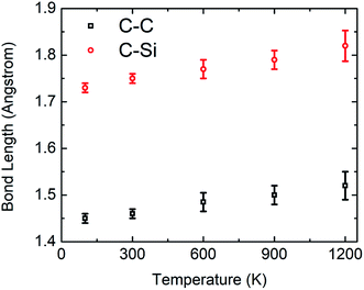 | ||
| Fig. 6 Variations of bond length between C–C and C–Si in relaxed SiG nanosheet with temperature during MD simulation. | ||
On the other hand, the C–C, C–Si and Si–Si bonds remain stable at a lower temperature experiencing insignificant thermal vibration or fluctuation due to temperature. Therefore, it breaks at higher tensile strain and gives high fracture stress. It is evident from these graphs, chiral effects, however, slowly diminishes with temperature. This corroborates that, at a higher temperature, thermal fluctuation dictates the failure mechanism over the elastic failure. We also found a loose temperature dependence of elastic modulus that indicates a small volumetric expansion of the doped nanosheet over a wide range of temperature. Additionally, we simulated some samples of graphene to compare the sensitivity of SiG to temperature and corresponding results are displayed in Table 2.
| Material | Armchair direction | Zigzag direction | Comments |
|---|---|---|---|
| Graphene | At 100 K, ∼130 GPa and ∼25% | At 100 K, ∼124 GPa and ∼22.4% | Armchair: ∼22% and ∼35.1% reduction in fracture stress and strain respectively |
| At 600 K, ∼101 GPa and ∼16.2% | At 600 K, ∼100 GPa and ∼17.9% | Zigzag: ∼18.5% and ∼20% reduction in fracture stress and strain respectively | |
| Silicon doped graphene (SiG) | At 100 K, ∼110 GPa and ∼19% | At 100 K, ∼99.2 GPa and ∼14.4% | Armchair: ∼20.4% and ∼28.94% reduction in fracture stress and strain respectively |
| At 600 K, ∼87.5 GPa and ∼13.5% | At 600 K, ∼83.3 GPa and ∼11.8% | Zigzag: ∼16% and ∼18% reduction in fracture stress and strain respectively |
Based on the above calculations, it could be inferred that in terms of fracture stress and strain, the temperature sensitivity of SiG is quite low compared to pristine graphene. This is because, the atomic mass of silicon (28.08 amu) is greater than carbon (12.01 amu), therefore it fluctuates less from its mean position due to thermal vibration.54,55,57 That's why the tensile strength of SiG does not considerably change with varying temperature compared to pristine graphene. This interesting finding also establishes the validity of our computational approach with continuum physics and experimental data.54,55,57
3.3 Effect of vacancy defects on the stress–strain behavior of SiG
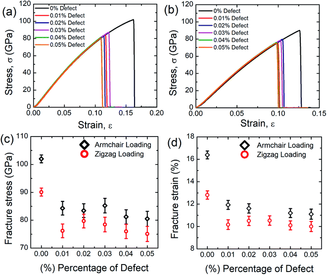
Fig. 7(a) and (b) represent the stress–stress response of SiG for different concentration of defects (mono-vacancy) at 300 K. Defects are introduced by removing carbon atoms randomly from the nanosheet as shown in Fig. S1 (ESI† of this article).Atomic defects are found in 2D materials, such as vacancies and other point defects. During the manufacturing processes of 2D materials, these defects can be formed by ion or electron irradiation.64 Specifically, mono-vacancies can result in local magnetic moments, whereas di-vacancies cause a direct-indirect bandgap transition, it has been stated that the defects have a strong influence on electrical, mechanical and thermal properties. However, it remains unclear how those defects affect the tensile properties of SiG.17,64–67
Defects are varied from 0.01 to 0.05% and the corresponding stress–strain response is recorded. It can be seen from these stress–strain curves that, as the concentration of defects increases, the peak value of the stress–strain curve decreases gradually. It is also evident from these graphs that SiG is very sensitive to defects, only 0.01% random carbon vacancy reduces the peak value in the stress–strain curve remarkably. It can also be observed that defected SiG exhibits brittle type fracture, which is analogous to other 2D materials. These results are translated into Fig. 7(c) and (d) showing variations of fracture stress and strain with the concentration of defects. From these figures, it can be seen that as the concentration of defects increases, both fracture stress and strain reduces monotonically.
These findings can be due to the missing random atoms that destroy the integrity of the stress field. Bond breakage occurs when the atomic fluctuation overcomes the coherent force, resulting in a disordered structure and an increase in the potential energy of the structure. Removing an atom from the structure creates a hole around the nearby atoms and some dangling bonds. This eventually allows for further fluctuation at the constituent bonds and contributes to chemical instabilities at the atoms that have been removed. Accordingly, in a stretched matrix both stress accumulation and mechanical instability happen which is also evident from MD simulation, profoundly illustrated in Fig. 8.17,64,65 Finally, this stress concentration around the vacancy defect results in the collapse of the surrounding members' bond systems, and the creation of the initial crack.17,64,65 The bonds in the defected area may, therefore, split much earlier during the deformation. As the percentage of defect increases, the ultimate tensile strength and critical strain of the material weaken considerably due to the impact of stress concentration.17,64,65 It is also worth to mention that, only a few concentration of defects reduces the fracture stress and strain of SiG substantially, but the further increment of defects don't affect the tensile properties (i.e. fracture stress and strain) of SiG significantly. This is because, defects, sometimes induce dislocation in the lattice, which hinders the nucleation of fracture and arrest the immediate catastrophic fracture as reported earlier.68,69 The anomaly for fracture stress and strain (0.03% vacancy for armchair loading and 0.02% vacancy for zigzag loading) could be attributed from the initial void produced by the bond break is blunt in form, this nucleation of void acts as a crack and it is stated that the radius of crack tip delays material failure.2 This kind of anomaly is reported earlier for stanene.2
Our MD calculations suggest that only 0.05% random removal of carbon from SiG reduces the fracture stress and fracture strain by ∼21% and ∼32.2%, respectively for armchair loading, and ∼16.7% and ∼22%, respectively for zigzag loading. We also simulated the tensile properties of the defected graphene sheet. Our MD results suggest that only 0.05% random carbon vacancy reduces the fracture strength and strain of graphene by ∼19% and ∼30% respectively for armchair direction and ∼14% and ∼20% respectively for zigzag direction. Defective graphene could endure more tensile strain compared to defect induced SiG. This reason is profoundly discussed in Section 3.4.
3.4 Effect of crack length on the stress–strain behavior of SiG
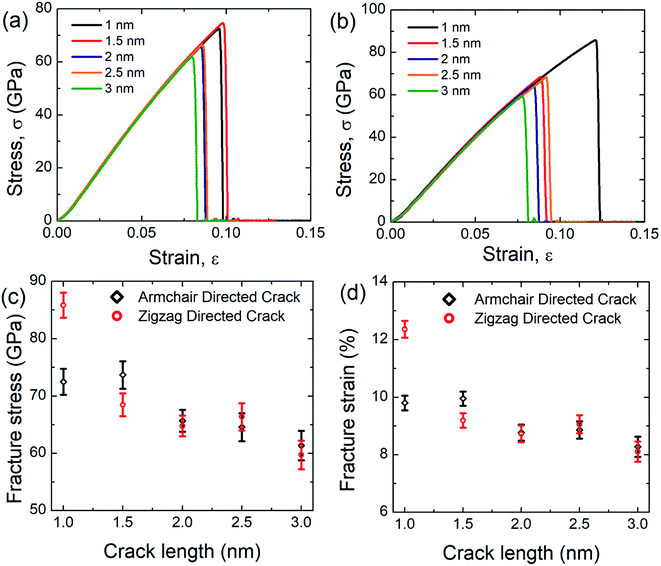
In this investigation, we simulated the tensile properties of pre-cracked SiG under uniaxial tension along the perpendicular to crack direction at 300 K and initial coordinates of the pre-cracked SiG nanosheet has been provided in the ESI of this article (Fig. S2†). The stress–strain response of pre-cracked SiG for armchair and zigzag directed crack has been shown in Fig. 9(a) and (b). It is evident from the stress–strain curve, as the crack length increases the area under the curve, that's the energy absorbed by the material before fracture monotonically decreases. Besides, stress–strain curves of pre-cracked SiG exhibits brittle type failure. We note that the fracture is a size-dependent process. In our MD simulations, we restricted our simulations to 30 nm × 30 nm sheet. At the nanoscale, SiG shows predominantly a brittle fracture behavior with a high crack propagation speed. For such a brittle nature, the material fracture is primarily dictated by the edge energy and at a moderate crack length, the fracture characteristics of the specimen are essentially predicted by Griffith's fracture criterion. For a more practical size domain, this study can be easily extended to the continuum domain using effective coarse-graining and adaptive atomistic-continuum numerical method reported by Budarapu et al.70 and another literature by Budarapu et al.71 It is expected that results from MD simulations will match very well with the atomistic finite element based calculations.72The results from stress–strain graphs are translated into Fig. 9(c) and (d) for better understanding. It is evident that as the crack length increases both fracture stress and strain decreases. This may be attributed to the faster bond breaking between C–C and C–Si and Si–Si is initiated by larger cracks by forming a plastic zone at the crack tip and this kind of fracture phenomenon is reported earlier for graphene,10,73 silicene,10,58 hBN,10 and stanene.2,20 Owing to the high local stress at the crack tip this plastic zone induces an irreversible deformation and thus facilitates bond breaking.10,58 The anomaly for fracture stress and strain as a function of crack length may be attributed to the bluntness of the crack tip that formed an asymmetric blunt crack to retain a particular crack length in the center of the nanosheet.2,10 Note that only 3 nm armchair directed crack reduces the fracture stress and strain of SiG by ∼32.5% and ∼36.30%, respectively while only 3 nm zigzag directed crack reduces the fracture stress and strain by ∼42% and ∼48%, respectively.
To investigate the crack sensitivity of SiG compared to free-standing graphene, we also simulated the tensile properties of pre-cracked graphene. It has been found that only 3 nm armchair directed crack reduces the fracture stress and strain of graphene by ∼24% and ∼29%, respectively. For zigzag directed crack, the decrement is ∼31% and ∼42%. As mentioned earlier, loading is always applied perpendicular to crack direction. So, it can be inferred that the degree of sensitivity to crack for SiG is larger compared to free-standing graphene. This could be attributed to the out plane deformation, lattice distortion, void, and reduction in bond energy of graphene, induced from silicon doping which promotes faster bond-breaking when a tensile load is applied.
3.5 Fracture toughness of SiG
Griffith theory is used to predict the theoretical fracture toughness of SiG.10,74where E is Young's modulus of SiG, Γ is the edge energy for SiG and ‘a’ is half of the crack length of the nanosheet. The function f(Ω) is a geometrical factor which can be determined by the following equation given below 10-
Here, Ω = 2a/W; W is the width of the SiG with a central crack of length 2a. The edge energy Γ has been calculated by dividing the difference between the energy of the SiG samples with and without cracks with newly created surface area.10 In this present investigation, we assumed an average value of Γ for all crack lengths for the theoretical prediction of fracture toughness (σf√a) by Griffith theory.10
The MD prediction of the fracture toughness is calculated by σf√a, where σf is the fracture stress of the pre-cracked SiG.10 From Fig. 10, it is evident that the estimated fracture toughness by MD simulations deviates from Griffith's theory. It is well known that Griffith's fracture criteria account for surface energy barrier to be the only restriction for crack propagation. According to this model, once the strain energy overcomes the surface energy, a fracture starts to propagate. However, in practice, atomically sharp crack tips become blunt due to local lattice relaxation of dangling atoms. Hence, local plastic zones are initiated near these crack tips. For a propagating crack, an additional plastic dissipation is now required to overcome. In our simulations, we observed crack widening, crack tip blunting and local distortions. This inherent deformation induces a plastic zone and thus larger available energy is required to initiate fracture process than that is predicted by Griffith's model. This type of lattice trapping effect was previously observed in graphene and its elemental analogues.10 For both armchair and zigzag crack, we notice that fracture toughness enhances with crack length, a feature that is not present in Griffith prediction. This implies that plastic dissipation is larger with larger cracks. We observe that at larger crack lengths there are additional local crack closing by 8 atom type defect formation. This defect has a bond parallel to loading direction and takes a significant amount of load. (Readers are referred to Fig. S3, ESI† of this article). Such local relaxation and crack closing are made possible by the silicon sites close to the crack. Since equilibrium C–Si bonds are larger than C–C bonds, they narrow down nearby crack opening and facilitate the edge healing. Since this behavior is promoted by local availability of silicon sites, crack edge healing is more pronounced for larger cracks. It rises the plastic dissipation for larger crack samples, deviating large cracked samples more from the Griffith prediction.61 Also, note that both graphene and SiG demonstrate a hexagonal lattice structure and a perfectly elliptically crack can't be maintained while Griffith's criterion is based on continuum mechanics assuming a perfectly elliptical crack. For even larger crack the fracture toughness is expected to approach towards the Griffith line again, indicating that a continuum view is viable at a very large crack.75
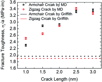 | ||
| Fig. 10 Fracture toughness of SiG with the varying crack length for both armchair and zigzag directed crack at 300 K. | ||
Rakib et al. reported fracture toughness of pre-cracked graphene by both MD simulation and Griffith's theory.10 Comparing our MD results with Rakib et al. it can be commented that, between SiG and graphene, MD prediction of fracture toughness of SiG with larger crack length deviates more from Griffith's criterion which indicates a larger plastic dissipation in the presence of silicon atoms. This is because, as the strain energy release rate is higher in pre-cracked SiG compared to graphene due to the lattice distortion and out of plane deformation around the crack tip caused by doping with silicon.
3.6 Fracture phenomenon of pre-cracked SiG
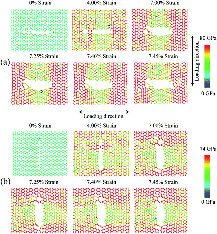
Fig. 11 shows the fracture phenomenon of 3 nm (a) armchair and (b) zigzag directed pre-cracked SiG for various strain level at 300 K. Loading is applied perpendicular to crack direction. It can be seen from Fig. 11(a) and (b), before applying the tensile load, lattice distortion is evident around the crack, caused by silicon doping. Our stress-based color-coding scheme expresses the fracture phenomenon with a clear understanding and also note that a zoomed inset of the critical region around the crack tip is provided.Failure should always start from the crack ends as stated by the classical stress concentration theory4 and our simulation results are in good agreement with that. The development of the red dumb-bell shaped regions at both ends of the cracks results from the high concentration of localized stress where irreversible deformation takes place. Additional loading increases the area of these zones and thus initiates the propagation of cracks.10,58 At ∼4% strain, the first bonds start to break near the crack tips and a defected area is generated accompanied by crack tip blunting (Fig. 11(a) and (b)). The resulting blunt crack-tip absorbs strain energy by further distortion and resist immediate crack propagation until ∼7% of strain. Besides, the repeatedly generated and annihilated dangling bond around the crack tip arrest the immediate catastrophic fracture. The similar kind of fracture characteristic is previously reported for defected graphene by Lehtinen et al.68 and Lee et al.69 At such high strain, with the growing stress concentration around the crack tip, a notable crack begins to spread, bond breakdown accumulates. Series of load parallel bonds between adjacent zigzag lines dissociate and create line defect along the zigzag direction that slows down crack propagation but cannot the arrest the brittle fracture. The pattern of fracture is observed to adopt the fracture behavior of typical 2D materials.20 For both armchair and zigzag cracks, we found that crack propagates preferentially to the zigzag direction (Fig. 11 and S4 of ESI† of this article), a trivial behavior of honeycomb crystal. This zigzag edge preference is attributed to smaller bond density thus a smaller cost of energy for bond rupture.
Fracture phenomenon of pre-cracked graphene is reported earlier by Rakib et al.10 For 3 nm pre-cracked graphene they found that nucleation of fracture occurs at 8.98% strain for armchair directed crack, and 9.34% strain for zigzag directed crack.10 But in the case of SiG, nucleation of fracture occurs too early, compared to graphene. This is because of lattice distortion, void, bond instability around the crack tip, caused by doping of silicon atom as mentioned earlier. Since atomic arrangement has already been distorted, by substitutional silicon atom, so pre-cracked SiG can't resist bond-breaking considerably at high strain compared to graphene.
3.7 Effect of strain rate on the mechanical properties of SiG
According to the theory of solid fracture, the strain rate is an important factor which affects the tensile properties of materials under loading condition. Besides, the high strain rate during MD simulation urges us to investigate the mechanical properties of SiG in terms of strain rate.The stress–strain response of SiG at various strain rate have been depicted in Fig. 12(a) and (b). It is evident that as strain rate increases, both fracture stress and strain increases as well. This is because at high strain rate material doesn't get enough time to break the interatomic bond thus showing a high tensile strength.6,20 On the other side, slower strain rate provides more time for atoms to oscillate from its mean position and thus increases the ability for atoms to overcome the energy threshold needed to break bonds.
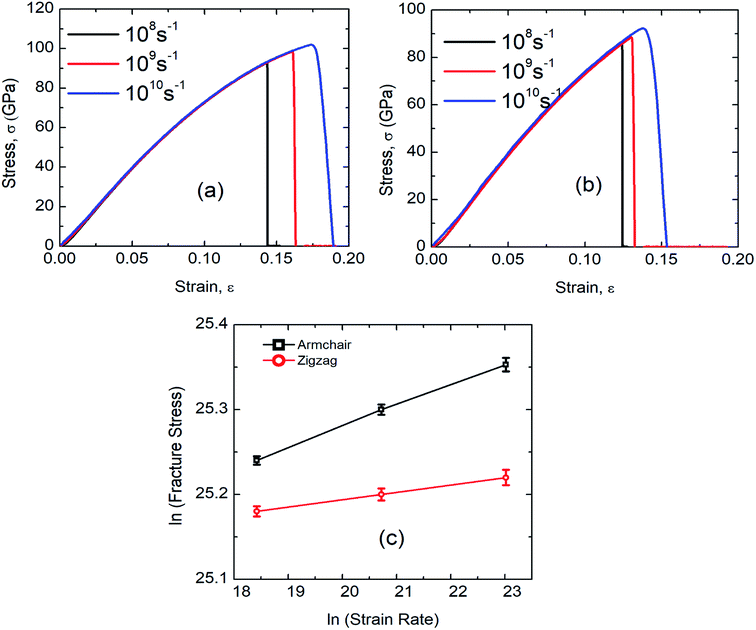 | ||
| Fig. 12 Stress–strain curve of SiG under (a) armchair (b) zigzag loading for different strain rate. (c) Effects of strain rate on fracture stress of SiG in logarithmic scale. | ||
Fracture stress and strain rate for a particular temperature can be related by,6,20
This equation can be written as,
![[small epsilon, Greek, macron]](https://www.rsc.org/images/entities/i_char_e0c6.gif) represents strain rate,
represents strain rate,  is an arbitrary constant, m is the strain rate sensitivity. At a particular temperature and strain, m denotes the ratio of change in ln
![[thin space (1/6-em)]](https://www.rsc.org/images/entities/char_2009.gif) σ to the change in ln
σ to the change in ln![[thin space (1/6-em)]](https://www.rsc.org/images/entities/char_2009.gif) ε. The value of m is obtained from the slope of the plot depicted in Fig. 12c. For the armchair and zigzag direction the equations are,
ε. The value of m is obtained from the slope of the plot depicted in Fig. 12c. For the armchair and zigzag direction the equations are,ln![[thin space (1/6-em)]](https://www.rsc.org/images/entities/char_2009.gif) σ = 24.75 + 0.026 σ = 24.75 + 0.026![[thin space (1/6-em)]](https://www.rsc.org/images/entities/char_2009.gif) ln ln![[thin space (1/6-em)]](https://www.rsc.org/images/entities/char_2009.gif) ![[small epsilon, Greek, macron]](https://www.rsc.org/images/entities/i_char_e0c6.gif) |
ln![[thin space (1/6-em)]](https://www.rsc.org/images/entities/char_2009.gif) σ = 25.01 + 0.00869 σ = 25.01 + 0.00869![[thin space (1/6-em)]](https://www.rsc.org/images/entities/char_2009.gif) ln ln![[thin space (1/6-em)]](https://www.rsc.org/images/entities/char_2009.gif) ![[small epsilon, Greek, macron]](https://www.rsc.org/images/entities/i_char_e0c6.gif) |
It can be observed that the sensitivity of strain rate along with armchair direction is ∼3 times greater than zigzag direction. This is because, in pristine graphene and SiG, two bonds in a unit cell are parallel to the armchair loading direction. These bonds are sensitive when subjected to the loading and strain rate as well. But in the case of zigzag direction, there are no bonds that are parallel to the loading direction.
4. Conclusions
In conclusion, the effect of silicon concentration on the mechanical properties of graphene has been studied. Modified Tersoff potential has been employed to define the interatomic interaction of atoms in the SiG systems. It is found that as the concentration of silicon increases both fracture stress and strain reduces notably. This reason is attributed to the reduction of bond energy, lattice distortion, out of plane deformation of graphene lattice, induced from doping with the silicon atom. The stress–strain curves show brittle type fracture for all concentration of silicon on graphene. Our MD simulation results suggest that only 5% silicon doping on graphene reduces the fracture stress and strain by ∼31.5% and ∼44.13%, respectively for armchair loading and, ∼37.5% and ∼42.5% for zigzag loading. Young's modulus demonstrates a strong inverse relationship with the concentration of silicon doping. It is found that as the concentration of silicon increases, chirality effects on the tensile properties of SiG deteriorates. Effect of temperature, defects and crack length on the mechanical behavior of SiG has been explored. Temperature studies suggest that decreasing the temperature increases the fracture stress and strain of SiG. Besides, we found that the degree of sensitivity to temperature of SiG is less than free-standing graphene. Defects and crack reduce the mechanical strength of SiG, moreover, SiG is more sensitive to defects and crack compared to graphene. Fracture toughness of SiG is investigated with varying crack length and compared with Griffith's theory. It has been found that samples with smaller cracks demonstrate a nice agreement with Griffith's criterion but the magnitude of fracture toughness for samples with large crack shows a larger deviation. So it can be concluded that Griffith's theory of brittle type fracture can't accurately predict the fracture of materials at the nanoscale. Fracture studies of pre-cracked SiG suggest that notable fracture nucleation occurs too early for SiG compared to free-standing graphene. Though bond-breaking is initiated too early for SiG, the catastrophic fracture is delayed due to the continuously generated and annihilated dangling bond around the crack tip, induced by silicon doping. Finally, we have investigated the tensile properties of SiG by varying the strain rate. As expected, at high strain rate SiG shows high tensile strength and the reason is elucidated in this paper.Conflicts of interest
There are no conflicts to declare.Acknowledgements
Authors would like to acknowledge Md Mahbubul Islam and Tawfiqur Rakib for their kind support in improving this manuscript.References
- S. Bae, S. J. Kim, D. Shin, J. H. Ahn and B. H. Hong, Towards industrial applications of graphene electrodes, Phys. Scr., 2012 DOI:10.1088/0031-8949/2012/T146/014024.
- S. Das, S. Mojumder, T. Rakib, M. M. Islam and M. Motalab, Atomistic insights into mechanical and thermal properties of stanene with defects, Phys. B, 2019 DOI:10.1016/j.physb.2018.10.035.
- R. Paul, T. Tasnim, S. Saha and M. Motalab, Atomistic analysis to characterize the impact of temperature and defects on the mechanical properties of germanene sheet, Mater. Res. Express, 2018 DOI:10.1088/2053-1591/aaa73d.
- T. Rakib, S. Saha, M. Motalab, S. Mojumder and M. M. Islam, Atomistic Representation of Anomalies in the Failure Behaviour of Nanocrystalline Silicene, Sci. Rep., 2017 DOI:10.1038/s41598-017-15146-6.
- R. Abadi, R. P. Uma, M. Izadifar and T. Rabczuk, Investigation of crack propagation and existing notch on the mechanical response of polycrystalline hexagonal boron-nitride nanosheets, Comput. Mater. Sci., 2017 DOI:10.1016/j.commatsci.2016.12.046.
- M. R. Arshee, S. Adnan, M. Motalab and P. Bose, Inherent mechanical properties of bilayer germanene coupled by covalent bonding, RSC Adv., 2019, 9, 34437–34450 RSC.
- A. A. Balandin, et al., Superior thermal conductivity of single-layer graphene, Nano Lett., 2008, 8, 902–907 CrossRef CAS PubMed.
- A. K. Geim and K. S. Novoselov, The rise of graphene, Nat. Mater., 2007 DOI:10.1038/nmat1849.
- G. Le Lay, E. Salomon, P. De Padova, J. M. Layet and T. Angot, The rise of elemental two-dimensional materials beyond graphene, Aust. J. Chem., 2014 DOI:10.1071/CH14194.
- T. Rakib, S. Mojumder, S. Das, S. Saha and M. Motalab, Graphene and its elemental analogue: a molecular dynamics view of fracture phenomenon, Phys. B, 2017 DOI:10.1016/j.physb.2017.04.009.
- A. Singh and A. Chandra, Graphene and graphite oxide based composites for application in energy systems, Phys. Status Solidi B, 2013 DOI:10.1002/pssb.201200972.
- A. Kausar, Advances in Polymer/Graphene Nanocomposite for Biosensor Application, NanoWorld J., 2018, 04 CAS.
- A. Ariharan, B. Viswanathan and V. Nandhakumar, Heteroatom Doped Multi-Layered Graphene Material for Hydrogen Storage Application, Graphene, 2016 DOI:10.4236/graphene.2016.52005.
- X. An, F. Liu and S. Kar, Optimizing performance parameters of graphene-silicon and thin transparent graphite-silicon heterojunction solar cells, Carbon, 2013 DOI:10.1016/j.carbon.2013.01.080.
- J. W. Jiang, J. S. Wang and B. Li, Young's modulus of graphene: a molecular dynamics study, Phys. Rev. B: Condens. Matter Mater. Phys., 2009 DOI:10.1103/PhysRevB.80.113405.
- C. Lee, X. Wei, J. W. Kysar and J. Hone, Measurement of the elastic properties and intrinsic strength of monolayer graphene, Science, 2008 DOI:10.1126/science.1157996.
- N. Jing, et al., Effect of defects on Young's modulus of graphene sheets: a molecular dynamics simulation, RSC Adv., 2012 10.1039/c2ra21228e.
- M. A. N. Dewapriya, R. K. N. D. Rajapakse and A. S. Phani, Atomistic and continuum modelling of temperature-dependent fracture of graphene, Int. J. Fract., 2014 DOI:10.1007/s10704-014-9931-y.
- Y. I. Jhon, Y. M. Jhon, G. Y. Yeom and M. S. Jhon, Orientation dependence of the fracture behavior of graphene, Carbon, 2014 DOI:10.1016/j.carbon.2013.09.051.
- S. Mojumder, A. Al Amin and M. M. Islam, Mechanical properties of stanene under uniaxial and biaxial loading: a molecular dynamics study, J. Appl. Phys., 2015 DOI:10.1063/1.4931572.
- X. Fan, Z. Shen, A. Q. Liu and J. L. Kuo, Band gap opening of graphene by doping small boron nitride domains, Nanoscale, 2012 10.1039/c2nr11728b.
- M. Houmad, H. Zaari, A. Benyoussef, A. El Kenz and H. Ez-Zahraouy, Optical conductivity enhancement and band gap opening with silicon doped graphene, Carbon, 2015 DOI:10.1016/j.carbon.2015.07.033.
- W. Zhang, et al., Opening an electrical band gap of bilayer graphene with molecular doping, ACS Nano, 2011 DOI:10.1021/nn202463g.
- A. Omidvar, Electronic structure tuning and band gap opening of nitrogen and boron doped holey graphene flake: the role of single/dual doping, Mater. Chem. Phys., 2017 DOI:10.1016/j.matchemphys.2017.09.025.
- A. J. Samuels and J. D. Carey, Molecular doping and band-gap opening of bilayer graphene, ACS Nano, 2013 DOI:10.1021/nn400340q.
- P. P. Shinde and V. Kumar, Direct band gap opening in graphene by BN doping: Ab initio calculations, Phys. Rev. B: Condens. Matter Mater. Phys., 2011 DOI:10.1103/PhysRevB.84.125401.
- S. Tang, J. Yu and L. Liu, Tunable doping and band gap of graphene on functionalized hexagonal boron nitride with hydrogen and fluorine, Phys. Chem. Chem. Phys., 2013 10.1039/c3cp44460k.
- P. A. Denis, Band gap opening of monolayer and bilayer graphene doped with aluminium, silicon, phosphorus, and sulfur, Chem. Phys. Lett., 2010 DOI:10.1016/j.cplett.2010.04.038.
- T. Hu and I. C. Gerber, Band gap modulation of bilayer graphene by single and dual molecular doping: a van der Waals density-functional study, Chem. Phys. Lett., 2014 DOI:10.1016/j.cplett.2014.10.034.
- P. K. Srivastava and S. Ghosh, Strain Induced Intrinsic Band Gap in Chemically Exfoliated Bilayer Graphene, Graphene, 2016 DOI:10.1166/graph.2015.1052.
- B. Huang, Electronic properties of boron and nitrogen doped graphene nanoribbons and its application for graphene electronics, Phys. Lett. A, 2011 DOI:10.1016/j.physleta.2010.12.050.
- S. J. Zhang, et al., Opening the band gap of graphene through silicon doping for the improved performance of graphene/GaAs heterojunction solar cells, Nanoscale, 2016, 8, 226–232 RSC.
- X. Bai, et al., Theoretical insights on the reaction pathways for oxygen reduction reaction on phosphorus doped graphene, Carbon, 2016 DOI:10.1016/j.carbon.2016.04.033.
- Y. Chen, B. Gao, J. X. Zhao, Q. H. Cai and H. G. Fu, Si-doped graphene: an ideal sensor for NO- or NO2-detection and metal-free catalyst for N2O-reduction, J. Mol. Model., 2012 DOI:10.1007/s00894-011-1226-x.
- Y. Chen, et al., Silicon-doped graphene: an effective and metal-free catalyst for NO reduction to N2O?, ACS Appl. Mater. Interfaces, 2013 DOI:10.1021/am400563g.
- M. D. Esrafili, N. Saeidi and P. Nematollahi, Si-doped graphene: a promising metal-free catalyst for oxidation of SO2, Chem. Phys. Lett., 2016 DOI:10.1016/j.cplett.2016.02.028.
- X. Mao, et al., Silicon-doped graphene edges: an efficient metal-free catalyst for the reduction of CO2 into methanol and ethanol, Catal. Sci. Technol., 2019 10.1039/c9cy01709g.
- W. Chen, et al., Theoretical study on the catalytic properties of single-atom catalyst stabilised on silicon-doped graphene sheets, Mol. Phys., 2020 DOI:10.1080/00268976.2019.1652368.
- B. Mortazavi and S. Ahzi, Molecular dynamics study on the thermal conductivity and mechanical properties of boron doped graphene, Solid State Commun., 2012 DOI:10.1016/j.ssc.2012.04.048.
- B. Mortazavi, S. Ahzi, V. Toniazzo and Y. Rémond, Nitrogen doping and vacancy effects on the mechanical properties of graphene: a molecular dynamics study, Phys. Lett. A, 2012 DOI:10.1016/j.physleta.2011.11.034.
- S. Plimpton, Fast parallel algorithms for short-range molecular dynamics, J. Comput. Phys., 1995 DOI:10.1006/jcph.1995.1039.
- G. Rajasekaran, R. Kumar and A. Parashar, Tersoff potential with improved accuracy for simulating graphene in molecular dynamics environment, Mater. Res. Express, 2016 DOI:10.1088/2053-1591/3/3/035011.
- J. Tersoff, Modeling solid-state chemistry: interatomic potentials for multicomponent systems, Phys. Rev. B: Condens. Matter Mater. Phys., 1989 DOI:10.1103/PhysRevB.39.5566.
- J. Tersoff, New empirical approach for the structure and energy of covalent systems, Phys. Rev. B: Condens. Matter Mater. Phys., 1988 DOI:10.1103/PhysRevB.37.6991.
- A. Stukowski, Visualization and analysis of atomistic simulation data with OVITO-the Open Visualization Tool, Modell. Simul. Mater. Sci. Eng., 2010 DOI:10.1088/0965-0393/18/1/015012.
- P. A. Hirel, A tool for manipulating and converting atomic data files, Comput. Phys. Commun., 2015 DOI:10.1016/j.cpc.2015.07.012.
- R. Paul et al., Study of uniaxial tensile properties of hexagonal boron nitride nanoribbons. in IEEE Region 10 Annual International Conference, Proceedings/TENCON, 2017, DOI:10.1109/TENCON.2017.8228335.
- T. H. Pial, T. Rakib, S. Mojumder, M. Motalab and M. A. S. Akanda, Atomistic investigations on the mechanical properties and fracture mechanisms of indium phosphide nanowires, Phys. Chem. Chem. Phys., 2018 10.1039/c7cp08252e.
- Q. X. Pei, Y. W. Zhang and V. B. Shenoy, A molecular dynamics study of the mechanical properties of hydrogen functionalized graphene, Carbon, 2010 DOI:10.1016/j.carbon.2009.11.014.
- M. Li, et al., Effect of defects on the mechanical and thermal properties of graphene, Nanomaterials, 2019 DOI:10.3390/nano9030347.
- M. S. Islam, et al., Molecular dynamics study of thermal transport in single-layer silicon carbide nanoribbons, AIP Adv., 2020 DOI:10.1063/1.5131296.
- Y. Apeloig and M. Karni, Substituent Effects on the Carbon–Silicon Double Bond. Monosubstituted Silenes, J. Am. Chem. Soc., 1984 DOI:10.1021/ja00334a036.
- T. L. Cottrell, The Strengths of Chemical Bonds, 2nd edn, 1966, DOI:10.1002/ange.19600721618.
- J. Walker, Fundamentals of Physics Halliday & Resnick, Wiley, 10th edn, 2014 Search PubMed.
- W. D. Callister and D. G. Rethwisch, Materials Science and Engineering, 9th edn, 2014, DOI:10.1016/j.str.2011.03.005.
- M. Schleberger and J. Kotakoski, 2D material science: defect engineering by particle irradiation, Materials, 2018 DOI:10.3390/ma11101885.
- A. Bahl, Essential of physical chemistry, S Chand & Co Ltd, 2010 Search PubMed.
- S. M. Nahid, et al., Tuning the mechanical properties of silicene nanosheet by auxiliary cracks: a molecular dynamics study, RSC Adv., 2018, 8, 30354–30365 RSC.
- Z. D. Sha, Q. X. Pei, Z. Ding, J. W. Jiang and Y. W. Zhang, Mechanical properties and fracture behavior of single-layer phosphorene at finite temperatures, J. Phys. D: Appl. Phys., 2015 DOI:10.1088/0022-3727/48/39/395303.
- S. Xiong and G. Cao, Molecular dynamics simulations of mechanical properties of monolayer MoS2, Nanotechnology, 2015 DOI:10.1088/0957-4484/26/18/185705.
- R. A. S. I. Subad, T. S. Akash, P. Bose and M. M. Islam, Engineered defects to modulate fracture strength of single layer MoS2: an atomistic study, Phys. B, 2020 DOI:10.1016/j.physb.2020.412219.
- Z. D. Sha, Q. X. Pei, K. Zhou, Z. Dong and Y. W. Zhang, Temperature and strain-rate dependent mechanical properties of single-layer borophene, Extreme Mech. Lett., 2018 DOI:10.1016/j.eml.2017.12.008.
- Y. Y. Zhang and Y. T. Gu, Mechanical properties of graphene: effects of layer number, temperature and isotope, Comput. Mater. Sci., 2013 DOI:10.1016/j.commatsci.2013.01.032.
- Z. D. Sha, Q. X. Pei, Y. Y. Zhang and Y. W. Zhang, Atomic vacancies significantly degrade the mechanical properties of phosphorene, Nanotechnology, 2016 DOI:10.1088/0957-4484/27/31/315704.
- X. Sun, Z. Fu, M. Xia and Y. Xu, Effects of vacancy defect on the tensile behavior of graphene, Theor. Appl. Mech. Lett., 2014 DOI:10.1063/2.1405102.
- S.-F. Xie, S.-D. Chen and A.-K. Soh, The Effect of Atomic Vacancies and Grain Boundaries on Mechanical Properties of GaN Nanowires, Chin. Phys. Lett., 2011, 28(6), 066201, DOI:10.1088/0256-307x/28/6/066201.
- S. Güryel, et al., Effect of structural defects and chemical functionalisation on the intrinsic mechanical properties of graphene, Phys. Chem. Chem. Phys., 2013 10.1039/c2cp43033a.
- O. Lehtinen, S. Kurasch, A. V. Krasheninnikov and U. Kaiser, Atomic scale study of the life cycle of a dislocation in graphene from birth to annihilation, Nat. Commun., 2013 DOI:10.1038/ncomms3098.
- G. Do Lee, E. Yoon, N. M. Hwang, C. Z. Wang and K. M. Ho, Formation and development of dislocation in graphene, Appl. Phys. Lett., 2013 DOI:10.1063/1.4775671.
- P. R. Budarapu, R. Gracie, S. P. A. Bordas and T. Rabczuk, An adaptive multiscale method for quasi-static crack growth, Comput. Mech., 2014 DOI:10.1007/s00466-013-0952-6.
- P. R. Budarapu, R. Gracie, S. W. Yang, X. Zhuang and T. Rabczuk, Efficient coarse graining in multiscale modeling of fracture, Theor. Appl. Fract. Mech., 2014 DOI:10.1016/j.tafmec.2013.12.004.
- J. Yao, Y. Xia, S. Dong, P. Yu and J. Zhao, Finite element analysis and molecular dynamics simulations of nanoscale crack–hole interactions in chiral graphene nanoribbons, Eng. Fract. Mech., 2019 DOI:10.1016/j.engfracmech.2019.106571.
- P. R. Budarapu, et al., Lattice orientation and crack size effect on the mechanical properties of graphene, Int. J. Fract., 2017 DOI:10.1007/s10704-016-0115-9.
- A. A. Griffith and M. V. I. Eng, The phenomena of rupture and flow in solids, Philosophical Transactions of the Royal Society of London. Series A, Containing Papers of a Mathematical or Physical Character, 1920 DOI:10.1098/rsta.1979.0079.
- B. Javvaji, et al., Mechanical properties of graphene: molecular dynamics simulations correlated to continuum based scaling laws, Comput. Mater. Sci., 2016 DOI:10.1016/j.commatsci.2016.08.016.
Footnote |
| † Electronic supplementary information (ESI) available. See DOI: 10.1039/d0ra06085b |
| This journal is © The Royal Society of Chemistry 2020 |

