 Open Access Article
Recent advancements in g-C3N4-based photocatalysts for photocatalytic CO2 reduction: a mini review
Runlu Liu
a,
Zhixin Chenb,
Yao Yaoa,
Yao Li
*a,
Waqas A. Cheema c,
Dawei Wang
 d and
Shenmin Zhu
 *a
*a
aState Key Laboratory of Metal Matrix Composites, Shanghai Jiao Tong University, Shanghai 200240, China. E-mail: smzhu@sjtu.edu.cn
bSchool of Mechanical, Materials, Mechatronics and Biomedical Engineering, University of Wollongong, Wollongong, 2522, Australia
cIndustrial Technology Development Center (ITDC), Higher Education Intelligence (HEI) Project, Pakistan
dSchool of Chemical Engineering, UNSW Australia, Sydney, NSW 2052, Australia
First published on 11th August 2020
Abstract
Carbon dioxide (CO2) is a very important micro-molecular resource. Using CO2 captured from the atmosphere for high-output synthesis of chemicals as raw materials has great significance and potential for various industrial applications. Since the industrial revolution in the 18th century, manmade CO2 emission has increased by 45%, which negatively impacts the planetary climate by the so-called greenhouse effect. Therefore, high-efficiency photocatalysis and photocatalysts for CO2 conversion have become the most important challenges and milestones throughout the world. In consideration of this, various catalysts have been explored. Among these, graphitic carbon nitride (g-C3N4) as a semiconductor is emerging as a highly promising photocatalyst for removing CO2 from the atmosphere. Moreover, due to its excellent chemical stability and unique band structure, g-C3N4 has exhibited significant application potential for photocatalysis. This review summarizes the advancements that have been made in the synthesis and photocatalytic applications of g-C3N4-based catalysts for CO2 reduction in recent years and explains the future challenges and prospects in this vital area of research.
1. Introduction
Carbon dioxide (CO2) is a major greenhouse gas that contributes approximately 20% to the greenhouse effect. Its emissions are increasing and are causing a significant negative influence on the overall climate and life on our planet. It was reported that the annual global carbon dioxide emissions have exceeded 30 billion tons, and only 1% of this amount is being removed annually.1 However, these emissions are not considered to be solely waste because CO2 is a very important micro-molecular resource for many industrial chemicals, such as methane, methyl alcohol, and dimethylformamide (DMF). Artificial synthesis of industrial-scale chemicals with CO2 captured from the atmosphere not only removes the harmful CO2, but also produces valuable chemical products for industries.Since 1970, it has been a challenge worldwide to develop a facile and efficient method for the photocatalytic reduction of CO2. Three types of CO2 photoreduction systems have been developed, i.e., the semiconductor photocatalytic system, the metal complex photocatalytic system, and the enzyme photocatalytic system.2 In 1979, Fujishima et al. reported photocatalytic CO2 reduction using semiconductors TiO2 and CdS as photocatalysts, and these were among the earliest photocatalytic systems for CO2 reduction.3 In 1983, Lehn et al. reported for the first time a CO2 reduction system using fac-Re(bpy)(CO)3Cl as a photocatalyst, and it exhibited high selectivity and high quantum yield.4 In 1986, Willner et al. reported a photocatalytic CO2 reduction system using enzymes as catalysts.5
Since their discoveries, all three types of CO2 photoreduction systems have been significantly developed. Due to the high substrate specificity, high conversion rates, excessive sensitivity, high cost, and narrow applicability of the enzymatic catalysts, their broad utilization has been limited.6 Thus, most of the interest has been focused on semiconductor or metal complex-based catalysts. In general, metal complex systems are based on homogeneous organic photocatalysts. Because all the metal atoms can serve as active sites, the catalytic efficiency and selectivity of the metal complex systems are sensitive to energy distribution. Moreover, due to the homogeneous structure, there are few side reactions accompanying metal complex photocatalysis.7,8 However, it is difficult to separate reactants from products because of the homogeneous structure, which limits the cyclic utilization and can be disadvantageous for sustainable development. In comparison, semiconductor-based photocatalysts are mostly heterogeneous catalysts, and with their use, it is easier to separate products from the reaction system.9 Furthermore, the photocatalytic performance can be improved through various structural and chemical modifications of the photocatalyst, e.g., porous semiconductor photocatalysts, doping10–14 or compositing of a semiconductor photocatalyst with other materials.15–17 Thus, there has been great interest and widespread usage of semiconductor photocatalysis during recent years.
Among the various types of semiconductors, graphitic carbon nitride (g-C3N4) is considered promising because it is composed of triazine rings and tri-s-triazine (heptazine) rings as its basic unit, and it forms a two-dimensional lamellar structure (Fig. 1).18 Because of the structure, it is insoluble in most solvents such as water, ethanol, ether, toluene, DMF, and tetrahydrofuran (THF).19 g-C3N4 is a typical polymer semiconductor with a band gap of 2.7 eV that can absorb blue-violet light with a wavelength less than 475 nm in the solar spectrum,20 and thus, it is a potential candidate for photocatalysis.21,22 In 2009, Wang et al. for the first time reported photocatalytic hydrogen production using g-C3N4 as a photocatalyst.23 In 2013, Peng et al. used g-C3N4 in CO2 photoreduction.24 This review will focus on the present pathways for the applications of g-C3N4 in the field of photocatalytic CO2 reduction. Finally, the conclusion of the article addresses the current challenges and future development of g-C3N4-based photocatalysts.
 | ||
| Fig. 1 s-Triazine (left) and tri-s-triazine (right) as tectons of g-C3N4.18 Copyright 2012 WILEY-VCH. | ||
2. Fundamentals of photocatalytic CO2 reduction on semiconductors
Photocatalytic CO2 reduction is a process where light energy is used as the input energy, and the product can be controlled by changing the reaction conditions and types of catalysts.25,26 The common reaction pathways are listed as follows.| CO2 + 2H+ + 2e− → HCOOH, E0 = −0.61 V | (I) |
| CO2 + 2H+ + 2e− → CO + H2O, E0 = −0.53 V | (II) |
| CO2 + 4H+ + 4e− → HCHO + H2O, E0 = −0.48 V | (III) |
| CO2 + 6H+ + 6e− → CH3OH + H2O, E0 = −0.38 V | (IV) |
| CO2 + 8H+ + 8e− → CH4 + 2H2O, E0 = −0.24 V | (V) |
The principle of photocatalytic CO2 reduction consists of five main steps: light adsorption (i), charge separation (ii), CO2 adsorption (iii), surface redox reaction (iv), and product desorption (v).27 To trigger the CO2 reduction reaction, the conduction band edge of the photocatalysts should be more negative than the reaction potential, and they are listed above (vs. NHE).28 To achieve efficient generation and transfer of photo-excited electrons and holes, certain modifications of photocatalysts are required. To increase the effectiveness of the process, a semiconductor-based photocatalyst should be designed considering these issues.
First, a semiconductor with a band gap of 2.0–3.0 eV is ideal for visible light adsorption.27 Second, the separation of electron–hole pairs is sufficiently large so that the recombination of electrons and holes is limited.30 Third, to enhance the adsorption of CO2, the surface area of photocatalysts should be enlarged, which can be accomplished by providing more active sites or introducing alkaline components into the photocatalysts.31 Fourth, to improve the efficiency of surface redox reactions, one can introduce a cocatalyst or prepare composites to enhance the charge transfer rate. Finally, accurate timing of the release of the products is necessary to increase the conversion and reaction rate.
3. g-C3N4 as photocatalyst
A good photocatalyst requires a suitable energy band structure to ensure light harvesting ability and efficient charge transfer. Among varieties of photocatalysts, oxide semiconductors usually have too large band gap energies to sufficiently utilize incident light, while the chalcogenide semiconductors often have a narrow band gap, which results in easy recombination of the photogenerated charge carriers (Fig. 2). In comparison, g-C3N4 is a non-metal semiconductor with a band gap of 2.7 eV and suitable conduction band (CB) and valence band (VB) positions, enabling it to absorb visible light. Moreover, g-C3N4 can be prepared by facile methods, and the microstructure of g-C3N4 can be easily adjusted to create pores as active sites or enlarge the surface area for more optimal light absorption. Because of these advantages, g-C3N4 is a superior photocatalyst for visible-light-driven CO2 reduction compared to TiO2 and other common photocatalysts. However, because the 2.7 eV band gap of g-C3N4 is insufficiently large, the separated electron–hole pairs tend to recombine, thus limiting the effective separation of charges and subsequent redox reactions. Although it has numerous Lewis base sites, e.g., Brønsted base sites and nucleophile sites that are favourable for CO2 adsorption, bulk g-C3N4 prepared by direct calcination has a relatively small surface area. Therefore, several modifications including structural tuning,31–37 elemental doping,38–45 addition of co-catalyst,46–60 and compositing61–70 have been used to increase the adsorption and obtain more effective charge separation.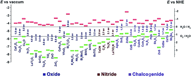 | ||
| Fig. 2 Band gap energies and CB (green) and VB (red) edge positions of the selected photocatalysts with respect to the vacuum level and NHE. The two dashed lines indicate the water redox reaction potentials.29 Copyright 2016 WILEY-VCH. | ||
3.1 g-C3N4 with nanostructures and/or defects
It is expected that g-C3N4 has good potential for CO2 fixation and activation. However, the bulk form obtained from some precursors has a small surface area, and thus, has low adsorption efficiency and catalytic activity. To alleviate this drawback, researchers have taken specific measures to increase the surface area and improve the functionality of g-C3N4. In this regard, Zhang et al. applied porous structured g-C3N4 to a CO2 photocatalytic reduction to CO under visible light irradiation.31 Moreover, the g-C3N4 was synthesized by calcination, using either melamine or melamine hydrochloride as the precursor. It was found that the latter has a surface area 39 times greater than bulk g-C3N4 due to the porous structure, but the performance of CO2 photoreduction was not obviously improved. This occurred because the porous structure not only endows g-C3N4 with a higher surface area but also enlarges the band gap, which resulted in more difficult electron excitation and the lower yield of CO2. Although it failed to improve the performance of CO2 photoreduction, there was still direct significance to this pioneering research in that the structural tuning of g-C3N4 resulted in great improvement of the photoreactivity.Thus far, different varieties of g-C3N4 nanostructures have been developed, such as porous structures, 1D nanorods, nanowires, 2D nanosheets, and 3D nanostructures.32–37 As a typical example, Zheng and Wang et al. imprinted helical g-C3N4 nanorods with chiral silicon dioxide as templates (Fig. 3).32 This helical structure caused multiple reflections of incident light, leading to an improved light-harvesting capability across the entire optical spectrum. Although the band gap increased from 2.66 eV to 2.75 eV, the helical g-C3N4 still exhibited an overall enhanced optical absorption compared to bulk g-C3N4. A lower photoluminescence (PL) intensity and a stronger PL quenching was measured for the helical g-C3N4 nanorods as compared to the bulk g-C3N4, which indicated that the recombination of photogenerated charge carriers in the helical g-C3N4 nanorods was suppressed.71 The CO production and selectivity of the helical g-C3N4 system during visible-light CO2 reduction reached 8.9 μmol and 96.7%, respectively. In recent years, there has been much experimentation with 2D g-C3N4 nanosheets because of their large specific surface area, which is advantageous for light harvesting and gas adsorption. Cao et al. prepared ultra-thin g-C3N4 nanosheets through a stepwise NH3-mediated thermal exfoliation approach.33 The resulting nanosheets were approximately 3 nm thick and were produced with a hierarchical structure due to the amine-induced assembly. This structure endowed g-C3N4 nanosheets with a much higher specific surface area, abundant active sites, shorter diffusion distance of charge carriers, and increased CO2 adsorption. Therefore, the yields of CH4 and CH3OH with g-C3N4 nanosheets as catalyst were 9.93 and 5.34 times higher than that with bulk g-C3N4 as catalyst, respectively.
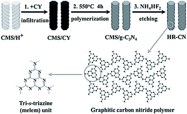 | ||
| Fig. 3 Synthetic process for helical nanorod-like graphitic carbon nitride (HR-CN) based on chiral mesoporous silica (CMS) as the template and cyanamide (CY) as the precursor.32 Copyright 2014, Wiley-VCH. | ||
Apart from structural tuning, the introduction of defects is also a useful method for promoting the photoactivity of g-C3N4. Zhang et al. introduced carbon vacancies into synthesized g-C3N4 with urea and heat treatment under an NH3 atmosphere to enhance CO photogeneration.34 The g-C3N4 with enriched C vacancies exhibited a CO evolution rate of 4.18 μmol g−1 h−1, which was 2.3 times higher than the evolution rate of pristine g-C3N4. The improved CO2 reduction performance was ascribed to greater CO2 adsorption and activation, an upshifted conduction band, increased charge carrier concentration, and prolonged lifetime. Furthermore, the reactive oxygen species (ROS) and electrochemical impedance spectroscopy (EIS) indicated that the C vacancies could weaken the exciton effect and elevate the charge carrier generation.
In another study, Chai et al. introduced N vacancies into ultrathin g-C3N4 nanosheets using NH4Cl as a dynamic gas template.35 The NH4Cl decomposed into NH3 and HCl gases upon heating, which formed a bubble film on the surface of the polymerized g-C3N4 nanosheets. As the π–π interlayer interactions in the g-C3N4 nanosheets became diminished with the expansion of the bubble film, an ultrathin bubble g-C3N4 film formed, and N vacancies were introduced afterwards by a post-treatment under a reducing atmosphere. The few-atomic-layered structure enlarged the exposed surface area, and this benefited charge carrier transportation. Additionally, N vacancies induced a mid-gap state, which facilitated multi-electron excitation in a two-step process and extended the optical absorption of the g-C3N4 nanosheets to the near infrared region, and thus, the utilization of solar energy was enhanced (Fig. 4). Furthermore, N vacancies could also result in an aftereffect where the decay lifetime was prolonged because the mid-gap state retarded the radiative recombination rate. The g-C3N4 nanosheets with N vacancies exhibited a 5.14-fold higher CH4 evolution rate than pristine g-C3N4. This pioneering work was intriguing and inspiring because it highlighted the synergistic effect of morphology control and vacancy modulation on photocatalytic CO2 reduction.
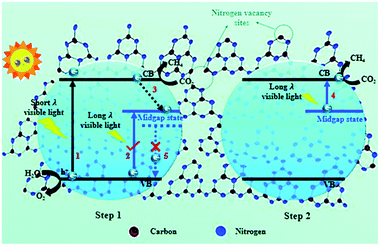 | ||
| Fig. 4 Schematic illustration of nitrogen defect-modified g-C3N4 atomic layers for photocatalytic CH4 evolution from CO2.35 Copyright 2019, Royal Society of Chemistry. | ||
Both structural adjustment and defect tuning are meant to change the energy band structure of g-C3N4 to enhance the light-harvesting ability and charge transfer efficiency, and they are the most convenient methods to improve the photocatalytic performance of g-C3N4.
3.2 Non-metal doped g-C3N4
Pristine g-C3N4 exhibits a poor performance due to low CO2 absorption and poor utilization of photo-excited charge carriers because of the deficiency of electron donation sites and unoptimized electronic structure.37 To address these challenges, heteroatom doping was developed to tune the electronic structure of g-C3N4. The doped elements included mainly B, C, O, P, and S.38–41In g-C3N4, N atoms are active sites for photocatalytic reactions, and the electrons are mainly localized around N atoms. Under light irradiation, transfer of excited electrons from N atoms to C atoms is difficult due to the localized electron structure.72–74 Moreover, the excited electrons are expected to transfer back for redox reaction, which increases the chances of recombination of the charge carriers. To address these problems, Liu et al. prepared boron-doped g-C3N4 by a one-step calcination using boric acid and urea as precursors.38 B atoms were doped into cavities between adjacent tri-s-triazine units through coordination with N atoms. The density functional theory (DFT) studies demonstrated that doping of B introduced a new electron excitation pathway from N (2px, 2py) to B (2px, 2py), which improved the charge transfer and localization, and thus the reaction dynamics. Furthermore, the doped B atoms altered the gas adsorption on the surface of g-C3N4 so that they could subsequently act as active sites. Consequently, the optimal B-doped g-C3N4 resulted in a 32-fold higher yield of CH4 than that of pure g-C3N4.
In another work, Tian et al. synthesized phosphorus-doped g-C3N4 nanotubes by calcinating a mixture of melamine and sodium hypophosphite monohydrate.39 The nanotube structure attained a much larger surface area than that of g-C3N4 nanosheets. The doping of phosphorus resulted in a shifting down of the conduction band and valence band of g-C3N4, and the band gap was narrowed by 0.12 eV (Fig. 5), which enhanced the optical absorption. The phosphorus doping also created additional amino groups in the surface of g-C3N4, which increased CO2 adsorption due to the acid–base interaction. As a result, the gas yields were 9.48 μmol g−1 for CO and 7.24 μmol g−1 for CH4, which were 3.12 and 13.9 times the yield of pristine g-C3N4, respectively. Similarly, Yu et al. fabricated sulfur-doped g-C3N4 (TCN) by a facile calcinating method using thiourea as the precursor.40 According to UV-Vis diffuse reflection spectra (UV-Vis DRS), the band gap of TCN was 2.63 eV, which was 0.07 eV narrower than that of un-doped g-C3N4 (MCN). This narrow band gap enabled TCN to absorb more solar energy and produce more charge carriers, thus improving the photocatalytic performance. According to the theoretical calculation, however, the band gaps of TCN and MCN were the same, but an impurity level was introduced due to sulfur doping on TCN. The photoelectrons could jump from the VB to the impurity level or from the impurity level to the CB. As a result, the CH3OH yield of TCN was 2.5 times greater than that of MCN.
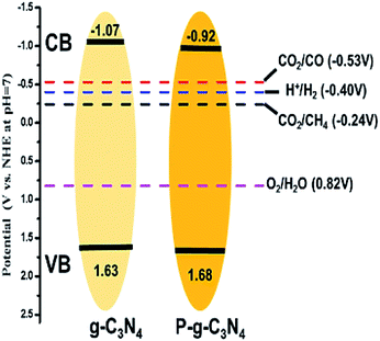 | ||
| Fig. 5 The electronic structure and all reaction reduction potentials of hydrogen evolution and CO2 conversion into CO and CH4.39 Copyright 2018, American Chemical Society. | ||
It is worth noting that many studies have been recently conducted on metal and non-metal co-doped g-C3N4 for CO2 photoreduction. Metal elements such as K, Na, and Co can improve the photocatalytic performance through a similar mechanism.42–45 Zheng et al. prepared N vacancy-rich g-C3N4 co-doped with B and K atoms through a one-step method.42 In this system, K functioned as an electron donor and promoted interlayer electron transfer, B assisted in maintaining a high reduction potential and counteracted the drawbacks of K, and N vacancies lowered the conduction band minimum (CBM) and promoted CO2 absorption. The synergistic effect of the multiple modifications significantly improved the CO2 reduction performance. The CH4 and CO produced in 5 h were 5.93 μmol g−1 and 3.16 μmol g−1, respectively, and 161% and 527% of the production of the pristine g-C3N4 occurred under the same conditions. It further suggested that the combination of doping and vacancies enhanced the photocatalytic performance of g-C3N4, and provides a new strategy for photocatalyst modification.
Overall, the non-metal doping increased the CO2 photoreduction activity of g-C3N4 by tuning the energy band structure, which manifested as a narrower band gap that provided more effective light absorption in a wider range of spectra, especially in the visible light region. The non-metal doping could also introduce an impurity level or a new electron excitation pathway to g-C3N4, which facilitated the charge transfer. Moreover, the doping process might introduce surface groups, which improved CO2 adsorption due to the acid–base interaction.
3.3 g-C3N4 with co-catalyst
In photocatalysis, suitable co-catalysts can serve as active sites for surface reactions and improve charge separation and charge utilization.75 For a semiconductor such as g-C3N4, frequently used co-catalysts include metal, carbon materials, reduction co-catalyst, and double co-catalyst.76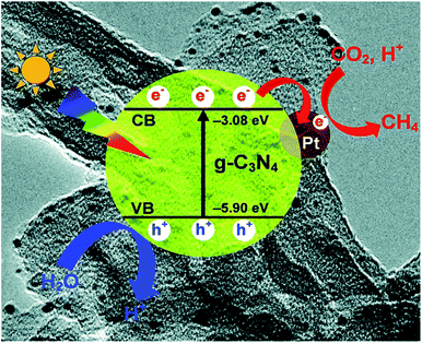 | ||
| Fig. 6 Photogenerated charge transfer process in the Pt/CN system for the reduction of CO2 to CH4 under visible light irradiation.47 Copyright 2014, Royal Society of Chemistry. | ||
Other noble metals are also frequently employed to modify g-C3N4.49,50 Currently, there are few CO2 reduction systems using non-noble metals.51,52 However, according to a DFT calculation, Mo could be an efficient co-catalyst on g-C3N4 for CO2–CO conversion.53
In another study, 3D porous g-C3N4/carbon nanosheets were prepared by simple pyrolysis and subsequent carbothermal activation.55 Gas-phase CO2 photoreduction experiments under simulated solar irradiation showed that the photocatalytic activity of the 3D g-C3N4 was 2 times that of the bulk g-C3N4 due to the introduction of carbon and the 3D porous structure. First, the hierarchical 3D porous architecture promoted CO2 transportation to active sites and accelerated the diffusion of products. Second, the 3D porous structure could have increased the light-harvesting ability. Furthermore, the photogenerated electrons could have effectively drifted from g-C3N4 to the hybrid carbon under the action of the inner electric field due to the quantum confinement effect, which inhibited the electron–hole pairs from combining and prolonged the lifetime of the photogenerated charge carriers. Finally, according to their X-ray photoelectron spectroscopy (XPS) analysis, there were partial electron-withdrawing carbon–oxygen groups on the surface of this composite, e.g., C–O, C![[double bond, length as m-dash]](https://www.rsc.org/images/entities/char_e001.gif) O, and O–C
O, and O–C![[double bond, length as m-dash]](https://www.rsc.org/images/entities/char_e001.gif) O groups, which could have facilitated the electron flow on the external surface. Thus, the recombination of electron–hole pairs was suppressed.
O groups, which could have facilitated the electron flow on the external surface. Thus, the recombination of electron–hole pairs was suppressed.
Carbon quantum dots (CQDs) doped onto g-C3N4 can also offer many advantages in CO2 photoreduction, such as reducing the band-gap, the electron-withdrawing effect, and the up-conversion effect.56 Recently, Tang et al. reported the hole-accepting effect of carbon dots in promoting selective CO2 reduction to methanol.57 The microwave-synthesized carbon dots have a pure graphite structure that facilitates efficient hole transfer to carbon dots and favours electron accumulation on the surface of g-C3N4. Moreover, the hole-accepting carbon dots can prevent the surface adsorption of methanol, which subsequently prevents the re-oxidation of produced methanol. As a result, the carbon dot-decorated g-C3N4 produced methanol from water and CO2 with nearly 100% selectivity to methanol. This work exhibited the great potential of carbon quantum dots in efficient and highly selective CO2 photoreduction.
Zhou et al. loaded molybdenum phosphide (MoP) onto g-C3N4.59 The introduction of MoP facilitated the separation and transfer of electron hole pairs, and increased light absorption throughout the UV and visible light spectrum without changing the absorption edge of g-C3N4, thus endowing the photocatalyst with a 4.5-fold higher production of CO compared with pristine g-C3N4. Pan et al. prepared NiS2 quantum dot-modified g-C3N4 photocatalysts by a hydrothermal method.60 The lower Fermi level and surficial metallicity resulted in the ability of NiS2 to become an ideal electron acceptor, which accelerated the separation of electron–hole pairs and inhibited their recombination. Additionally, the introduction of NiS2 quantum dots provided more active sites and contributed to close interface contact. Therefore, the CO yield on NiS2/g-C3N4 reached 10.68 μmol g−1 h−1, which was 3.88 times higher than that on pristine g-C3N4.
Co-catalysts significantly improve the photocatalytic performance of g-C3N4 by facilitating the charge carrier transfer and suppressing the recombination of electron–hole pairs. It is worth noting that some metal oxides, metal phosphides, and metal sulfides can form heterojunctions together with g-C3N4, which is further discussed below.
3.4 g-C3N4-based composites
Combining g-C3N4 with other semiconductors to form heterojunctions can facilitate electron transfer, light utilization, and even CO2 adsorption. Hence, it is a highly recommended strategy for CO2 photocatalytic reduction using g-C3N4.Layered double hydroxides (LDHs) are a class of compounds made up of positively charged brucite-like layers with an interlayered region containing charge-compensating anions and solvation molecules (Fig. 7).81 By using a general formula [MII1−xMIIIx(OH)2]x+·(An−)x/n·mH2O (M = metal, A = interlayer anion), it was determined that LDHs exhibited some physicochemical properties that are in favour of CO2 adsorption, e.g., large surface areas, positive surface charges, and compositional flexibilities.76 Xu et al. used Mg–Al-LDH nanosheets to enrich CO2 on the surface of g-C3N4 by the exploitation of its anion-exchange capacity.61 LDH/g-C3N4 was assembled via electrostatic interaction combined with Pd co-catalyst, and it showed a remarkably enhanced CH4 yield compared to the yield without LDH. Moreover, enriched CO2 existed in the form of interlayered CO32− in the LDH, which could have been more efficiently reduced. Apart from LDH, metal organic frameworks (MOFs) have unique structural properties such as high surface area, high porosity, and low crystal density, as well as high thermal and chemical stability, and thus, they can also be utilized to enhance CO2 adsorption on g-C3N4.62
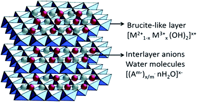 | ||
| Fig. 7 Schematic illustration of layered double hydroxide structure and chemical.80 Copyright 2017, Elsevier. | ||
(a) g-C3N4-based type II heterojunction. The heterojunction is a type of p–n junction. It refers to two semiconductor materials that have been combined through surface assembly or internal crystal interface crosslinks, which accelerates the separation of electron–hole pairs by the construction of a built-in electric field.
In terms of the energy band, heterojunctions fall into three categories: (i) type I heterojunction, where the forbidden gap of one component is completely covered by that of the other component; (ii) type II heterojunction, where the forbidden bands of the two components are staggered, and the semiconductor has a more negative CB and a less positive VB; (iii) type III heterojunction, where the forbidden bands of the two components are completely separated. The most investigated photocatalysis systems are usually type II heterojunctions. When a photocatalytic reaction takes place, the photogenerated electrons transfer from the more negative CB to the CB of the other semiconductor and generate a reduction reaction, while the holes transfer from the more positive VB to VB of the other semiconductor and generate an oxidation reaction.
One can construct a type II heterojunction system with g-C3N4 and another semiconductor with a more negative CB position or a more positive VB position (Fig. 8). Commonly, there are few semiconductors whose CB position is more negative than that of g-C3N4, and thus, it is easy to construct a g-C3N4-based heterojunction, as illustrated in Fig. 8b. Many metal oxides, sulfides, halides, and other semiconductors are used for such a system.21 The construction of the heterostructure plays a significant role in its photocatalytic performance and stability.82,83
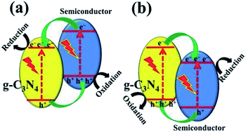 | ||
| Fig. 8 Charge transfer in the conventional type II g-C3N4-based heterojunction systems composed of g-C3N4 and another semiconductor (a) with more negative CB and (b) with more positive VB.21 Copyright 2017, Wiley-VCH. | ||
(b) g-C3N4-based Z-scheme heterojunction. The Z-scheme heterojunction, mimicking the photosynthesis of plants, was first proposed to solve the problem that a single photocatalyst could not split water to simultaneously produce both hydrogen and oxygen. A classic Z-scheme photocatalytic system consists of two photoluminescence processes and a series of redox reactions, and the electron transfer takes place in two optical systems (SI and SII).84 Different from type II heterojunctions, the electrons excited on SI transfer to SII through an electronic mediator and combine with holes generated on SII (Fig. 9a). Consequently, the electron–hole pairs generated in each semiconductor are separated, while the high reduction and oxidation abilities of the electrons and holes, respectively, are maintained.21,85 This mechanism involved with a mediator is known as the indirect Z-scheme. There is another type of mediator-free charge transfer mechanism, namely, the direct Z-scheme mechanism. In the direct Z-scheme mechanism, the photogenerated electrons on SI are directly transferred to SII and combined with the holes in SII (Fig. 9b).86,87 This results in direct contact between the two semiconductors and accelerates the charge transfer between the two components, which not only increases the reaction efficiency but also reduces the cost.
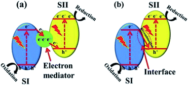 | ||
| Fig. 9 Z-scheme charge transfer between semiconductors (a) with or (b) without an electron mediator.21 Copyright 2017, Wiley-VCH. | ||
Li et al. synthesized an indirect Z-scheme BiOI/g-C3N4 heterojunction using a simple deposition method.63 The composite at an optimal fraction of 7.4 wt% BiOI exhibited a significantly enhanced CO yield of 17.9 μmol g−1 in a CO2 photoreduction test. The indirect Z-scheme charge transfer mechanism was confirmed through a series of characterizations including UPS, XPS, and DRS. A contrast test was executed to confirm the roles of intermediate I3−/I− pairs. In another study, an Al–O-bridged g-C3N4/α-Fe2O3 heterojunction was prepared using a two-step wet chemical method with AlCl3 aqueous solution as the Al–O source.64 The Al–O bridges significantly promoted charge transfer and separation and consequently enhanced the CO2 photoreduction performance (Fig. 10). The composite exhibited an approximately 4-fold enhancement of CO production (24 μmol g−1 h−1). Due to the existence of a charge transfer mediator, this type of Z-scheme heterojunction requires well-designed structures to achieve high charge separation and transfer efficiencies. In contrast, the charge transfers in direct Z-scheme heterojunctions are accelerated by the interface contacts, and there are high reaction efficiencies and low cost with direct Z-scheme heterojunctions. Therefore, there has been increasing interest in direct Z-scheme heterojunctions in recent years.
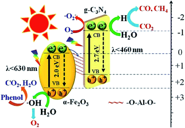 | ||
| Fig. 10 Schematic showing the transfer and separation of photo-induced charges in the fabricated Al–O-bridged g-C3N4/α-Fe2O3 nanocomposites and the induced photochemical reactions.64 Copyright 2018, Elsevier. | ||
Wong et al. also fabricated a direct Z-scheme heterojunction consisting of urchin-shaped α-Fe2O3 and a g-C3N4 nanosheet.65 Without using any sacrificial agent or co-catalyst, the Z-scheme hybrid had a 2.2-fold higher CO evolution rate as compared to pristine g-C3N4, consisting of up to 27.2 μmol g−1 h−1, which is also higher than that of an Al–O-bridged g-C3N4/α-Fe2O3 heterojunction. The introduction of 3D α-Fe2O3 not only narrows the band gap, increases the light absorption, and results in a high usage of optical energy, but it also increases the binding energy and CO2 adsorption so that additional CO2 molecules can participate in the reaction over a longer time span. Additionally, the direct Z-scheme structure facilitates the electron–hole separation in both α-Fe2O3 and g-C3N4, thus improving the reduction ability of photoelectrons in the conduction band of g-C3N4. The improved light harvesting, CO2 adsorption, and separation of charge carriers all contributed to the improved CO2 photoreduction performance.
There are many other materials that can be compounded with g-C3N4 to fabricate direct Z-scheme heterojunctions for photocatalytic CO2 reductions, e.g., ZnO, NiAl-LDH, and Bi2S3. Most of these are also well designed in terms of structure for further enhancements in CO2 photoreduction yields.66–68 For instance, Ogale et al. synthesized a 2D g-C3N4/NiAl-LDH heterojunction with strong electrostatic interactions between positively charged NiAl-LDH and negatively charged g-C3N4.66 The enhancement of the photocatalytic activity was mainly ascribed to the excellent interfacial contacts at the 2D/2D interface. The large contact area between the NiAl-LDH and g-C3N4 subsequently suppressed charge carrier recombination and improved the transfer and separation of photogenerated charge carriers. Guo et al. synthesized Bi2S3 quantum dots/g-C3N4 composites, where the Bi2S3 quantum dots were uniformly dispersed on g-C3N4, and this increased the light absorption and the separation of electron–hole pairs. A series of characterizations demonstrated the Z-scheme mechanism. The heterojunction exhibited 4-fold higher CO yield than the pristine g-C3N4.67
The photocatalytic mechanism of Z-scheme heterojunctions can be revealed by PL analysis and DFT calculations. Yu et al. prepared a g-C3N4/ZnO binary composite for photocatalytic CO2 reduction to CH3OH.68 The photocatalytic activity exhibited 2.3-fold enhancement compared with pure g-C3N4. The possible photocatalytic mechanism was verified by carrying out a PL analysis of hydroxyl radicals (˙OH) produced on pure g-C3N4, pure ZnO, and the composite. In terms of thermodynamics, the ˙OH and ˙O2− can only be produced by photogenerated holes from the VB of the ZnO and electrons from the CB of the g-C3N4, respectively. According to the double-transfer mechanism, neither ˙OH nor ˙O2− could be produced in the composite system, which implied that it was likely that the charge transfer followed the Z-scheme mechanism. This observation was supported by calculating the charge carrier effective mass and separating tendency of photogenerated electron–hole pairs using a DFT calculation. It was found that ZnO has a much higher relative effective mass of electrons and holes  indicating that the excited electrons of ZnO have a higher tendency to transfer, and thus, the charge transfer is more likely to originate from the ZnO to g-C3N4 instead of the opposite direction.88 These findings support the rationality of the Z-scheme mechanism.
Maeda et al. synthesized a heterogeneous photocatalyst consisting of a ruthenium (Ru) complex and g-C3N4. The former served as the catalytic unit and the latter as a light-harvesting unit, respectively. The electronic interactions between the two components enable the electrons to transfer from g-C3N4 into ruthenium.69 With trans-(Cl)-[Ru[4,4′-(CH2PO3H2)2-2,2′-bipyridine](CO)2Cl2] (RuP) as catalyst and a DMA![[thin space (1/6-em)]](https://www.rsc.org/images/entities/char_2009.gif) :
:![[thin space (1/6-em)]](https://www.rsc.org/images/entities/char_2009.gif) TEOA mixture (4
TEOA mixture (4![[thin space (1/6-em)]](https://www.rsc.org/images/entities/char_2009.gif) :
:![[thin space (1/6-em)]](https://www.rsc.org/images/entities/char_2009.gif) 1, v/v) as solvent, CO2 was reduced to HCOOH and CO with a selectivity of 80% for HCOOH, and the turnover number (TON) reached 1061 after 20 h of irradiation. The apparent quantum yield was 5.7% at 400 nm, which is higher than the performance reported in earlier studies. Jain et al. combined g-C3N4 with cobalt(II) phthalocyanine tetracarboxylate (CoPc-COOH) in various ratios to form numerous complex-semiconductor hybrid photocatalysts.70 The CO2 photoreduction activities of the synthesized CoPc-COOH, g-C3N4, and g-C3N4/CoPc-COOH were tested in a water/DMF environment using triethylamine (TEA) as a sacrificial agent. After a 24 h period of visible light irradiation, the CH4 yield of the g-C3N4/CoPc-COOH was 12.9 mmol g−1, which is 7.3 and 10.9 times higher than that of CoPc-COOH and g-C3N4, respectively. The improved photocatalytic efficiency was ascribed to the higher CO2 concentration resulting from the binding ability of CoPc-COOH to CO2.
1, v/v) as solvent, CO2 was reduced to HCOOH and CO with a selectivity of 80% for HCOOH, and the turnover number (TON) reached 1061 after 20 h of irradiation. The apparent quantum yield was 5.7% at 400 nm, which is higher than the performance reported in earlier studies. Jain et al. combined g-C3N4 with cobalt(II) phthalocyanine tetracarboxylate (CoPc-COOH) in various ratios to form numerous complex-semiconductor hybrid photocatalysts.70 The CO2 photoreduction activities of the synthesized CoPc-COOH, g-C3N4, and g-C3N4/CoPc-COOH were tested in a water/DMF environment using triethylamine (TEA) as a sacrificial agent. After a 24 h period of visible light irradiation, the CH4 yield of the g-C3N4/CoPc-COOH was 12.9 mmol g−1, which is 7.3 and 10.9 times higher than that of CoPc-COOH and g-C3N4, respectively. The improved photocatalytic efficiency was ascribed to the higher CO2 concentration resulting from the binding ability of CoPc-COOH to CO2.
For the g-C3N4/metal complex photocatalytic system, the interaction between g-C3N4 and metal complex plays an important role in the enhancement of charge transfer migration and suppression of charge recombination. To maximize the interaction, either π–π interaction between the tri-s-triazine unit of g-C3N4 and organic ligands or hydrogen bonds/covalent bonds between the functional groups can make positive contributions.
4. Conclusions
We reviewed the recent progress on g-C3N4-based materials for photocatalytic reduction of CO2. Furthermore, the basic properties of g-C3N4, and the principles and main steps of CO2 photoreduction have been critically elaborated. Additionally, different types of g-C3N4-based composites were compared, e.g., pristine g-C3N4, non-metal doped g-C3N4, g-C3N4 with co-catalysts, g-C3N4-based semiconductors, and g-C3N4/metal complex. Among the g-C3N4-based photocatalysts for CO2 reduction, g-C3N4-based semiconductors are most frequently used and have attracted the most interest. The Z-scheme structure, especially direct Z-scheme heterojunctions, realize charge transfer through interface contact, which accelerates charge transfer and leads to increased reaction efficiency and reduced cost. Hence, direct Z-scheme heterojunctions have attract more interest in recent years. Moreover, combined with other treatments such as elemental doping and structural fabrication, the photocatalytic efficiency of g-C3N4-based materials can be further increased. However, compared to g-C3N4/metal complex systems, a heterogeneous photocatalysis system based on semiconductor photocatalysts exhibits relatively lower utilization of light and depressed photocatalytic efficiency. By improving the interaction between the active sites and light-harvesting unit and optimizing the reaction conditions, g-C3N4/metal complex photocatalysts can increase the conversion efficiency greater than 10 fold, but this can complicate separation and recycling.In view of the above challenges, significant efforts have been made to combine homogeneous and heterogeneous photocatalysts to obtain high efficiency and high oxidation ability. For the heterogeneous photocatalytic system, strategies were mainly focused on three approaches: (i) tuning the surface properties of g-C3N4 to enhance the adsorption or activation of CO2, (ii) tuning the band structure for more optimal light utilization and photogenerated charge transfer, and (iii) reasonable design of a reaction pathway to accelerate the interface reaction. With laboratory-grade reactions, greater than 90% yield and selectivity of a product could be attained, which is much better than an industrial grade CO2 conversion. Due to financial constraints and industrial scale, these systems are not widely applicable to industrial production. However, future recommended pathways will enable the development of more efficient and sustainable technologies for the g-C3N4 photoreduction of CO2 so that a cleaner environment will exist for future generations.
Conflicts of interest
There are no conflicts to declare.Acknowledgements
This work was supported by National Key R&D Program of China [2016YFA0202900, 2016YFC1402400], National Natural Science Foundation of China [51672173, U1733130], MOE Joint Foundation [6141A02022264], Shanghai Science and Technology committee [17JC1400700, 18520744700, 18JC1410500], Science and Technology Planning Project of Guangdong Province [2016A010103018]. The authors gratefully acknowledge the Shanghai Synchrotron Radiation Facility (SSRF).References
- M. Aresta, A. Dibenedetto and A. Angelini, Chem. Rev., 2014, 114, 1709–1742 CrossRef CAS PubMed.
- X. Liu, S. Inagaki and J. Gong, Angew. Chem., Int. Ed., 2016, 55, 14924–14950 CrossRef CAS PubMed.
- T. Inoue, A. Fujishima, S. Konishi and K. Honda, Nature, 1979, 277, 637–638 CrossRef CAS.
- J. Hawecker, J. M. Lehn and R. Ziessel, J. Chem. Soc., Chem. Commun., 1983, 9, 536–538 RSC.
- I. Willner, D. Mandler and A. Riklin, J. Chem. Soc., Chem. Commun., 1986, 13, 1022–1024 RSC.
- W. Wang, J. Soulis, Y. J. Yang and P. Biswas, Aerosol Air Qual. Res., 2014, 14, 533–549 CrossRef CAS.
- J. Qin, V. A. Larionov, K. Harms and E. Meggers, ChemSusChem, 2019, 12, 320–325 CrossRef CAS PubMed.
- Y. Guo, P. Yang, S. Zhang, B. Jiang, A. Khan, L. Zhu, Z. Fu and Z. Fan, Iran. Polym. J., 2018, 27, 153–159 CrossRef CAS.
- F. Chen, X. Jiang, L. Zhang, R. Lang and B. Qiao, Chin. J. Catal., 2018, 39, 893–898 CrossRef CAS.
- W. Zhou, W. Li, J. Wang, Y. Qu, Y. Yang, Y. Xie, K. Zhang, L. Wang, H. Fu and D. Zhao, J. Am. Chem. Soc., 2014, 136, 9280–9283 CrossRef CAS PubMed.
- N. Tian, Y. Zhang, X. Li, K. Xiao, X. Du, F. Dong, G. I. N. Waterhouse, T. Zhang and H. Huang, Nano Energy, 2017, 38, 72–81 CrossRef CAS.
- C. Li, G. Chen, J. Sun, J. Rao, Z. Han, Y. Hu, W. Xing and C. Zhang, Appl. Catal., B, 2016, 188, 39–47 CrossRef CAS.
- Q. Zhang, D. Q. Lima, I. Lee, F. Zaera, M. Chi and Y. Yin, Angew. Chem., Int. Ed., 2011, 50, 7088–7092 CrossRef CAS PubMed.
- L. Jiang, X. Yuan, G. Zeng, X. Chen, Z. Wu, J. Liang, J. Zhang, H. Wang and H. Wang, ACS Sustainable Chem. Eng., 2017, 5, 5831–5841 CrossRef CAS.
- T. Xu, L. Zhang, H. Cheng and Y. Zhu, Appl. Catal., B, 2011, 101, 382–387 CrossRef CAS.
- S. D. Perera, R. G. Mariano, K. Vu, N. Nour, O. Seitz, Y. Chabal and K. J. Balkus, ACS Catal., 2012, 2, 949–956 CrossRef CAS.
- C. Chen, W. Cai, M. Long, B. Zhou, Y. Wu, D. Wu and Y. Feng, ACS Nano, 2010, 4, 6425–6432 CrossRef CAS PubMed.
- Y. Wang, X. Wang and M. Antonietti, Angew. Chem., Int. Ed., 2012, 51, 68–89 CrossRef CAS PubMed.
- E. G. Gillan, Chem. Mater., 2000, 12, 3906–3912 CrossRef CAS.
- J. Zhang, B. Wang and X. Wang, Acta Phys.-Chim. Sin., 2013, 29, 1865–1876 CAS.
- J. Fu, J. Yu, C. Jiang and B. Cheng, Adv. Energy Mater., 2018, 8, 1701503 CrossRef.
- L. Jiang, X. Yuan, Y. Pan, J. Liang, G. Zeng, Z. Wu and H. Wang, Appl. Catal., B, 2017, 217, 388–406 CrossRef CAS.
- X. Wang, K. Maeda, A. Thomas, K. Takanabe, G. Xin, J. M. Carlsson, K. Domen and M. Antonietti, Nat. Mater., 2009, 8, 76–80 CrossRef CAS PubMed.
- J. Mao, T. Peng, X. Zhang, K. Li, L. Ye and L. Zan, Catal. Sci. Technol., 2013, 3, 1253–1260 RSC.
- Y. Li, R. Ma, L. He and Z. Diao, Catal. Sci. Technol., 2014, 4, 1498–1512 RSC.
- F. D. Meylan, V. Moreau and S. Erkman, J. CO2 Util., 2015, 12, 101–108 CrossRef CAS.
- J. Wu, Y. Huang, W. Ye and Y. Li, Adv. Sci., 2017, 4, 1700194 CrossRef PubMed.
- J. Lee, D. C. Sorescu and X. Deng, J. Am. Chem. Soc., 2011, 133, 10066–10069 CrossRef CAS PubMed.
- Q. Lu, Y. Yu, Q. Ma, B. Chen and H. Zhang, Adv. Mater., 2016, 28, 1917–1933 CrossRef CAS PubMed.
- Y. S. Seo and S. G. Oh, Korean J. Chem. Eng., 2019, 36, 2118–2124 CrossRef CAS.
- G. Dong and L. Zhang, J. Mater. Chem., 2012, 22, 1160–1166 RSC.
- Y. Zheng, L. Lin, X. Ye, F. Guo and X. Wang, Angew. Chem., Int. Ed., 2014, 53, 11926–11930 CrossRef CAS PubMed.
- P. Xia, B. Zhu, J. Yu, S. Cao and M. Jaroniec, J. Mater. Chem. A, 2017, 5, 3230 RSC.
- M. Shen, L. Zhang, M. Wang, J. Tian, X. Jin, L. Guo, L. Wang and J. Shi, J. Mater. Chem. A, 2019, 7, 1556–1563 RSC.
- J. Tang, X. Kong, B. J. Ng, Y. H. Chew, A. R. Mohamed and S. P. Chai, Catal. Sci. Technol., 2019, 9, 2335–2343 RSC.
- X. Wu, H. Ma, W. Zhong, J. Fan and H. Yu, Appl. Catal., B, 2020, 271, 118899 CrossRef CAS.
- X. Wu, D. Gao, H. Yu and J. Yu, Nanoscale, 2019, 11, 9608 RSC.
- J. Fu, K. Liu, K. Jiang, H. Li, P. An, W. Li, N. Zhang, H. Li, X. Xu, H. Zhou, D. Tang, X. Wang, X. Qiu and M. Liu, Adv. Sci., 2019, 6, 1900796 CrossRef CAS PubMed.
- B. Liu, L. Ye, R. Wang, J. Yang, Y. Zhang, R. Guan, L. Tian and X. Chen, ACS Appl. Mater. Interfaces, 2018, 10, 4001–4009 CrossRef CAS PubMed.
- K. Wang, Q. Li, B. Liu, B. Cheng, W. Ho and J. Yu, Appl. Catal., B, 2015, 176–177, 44–52 CAS.
- S. Samanta, R. Yadav, A. Kumar and A. K. Sinha, Appl. Catal., B, 2019, 259, 118054 CrossRef CAS.
- K. Wang, J. Fu and Y. Zheng, Appl. Catal., B, 2019, 254, 270–282 CrossRef CAS.
- S. Wang, J. Zhan, K. Chen, A. Ali, L. Zeng, H. Zhao, W. Hu, L. Zhu and X. Xu, ACS Sustainable Chem. Eng., 2020, 8, 8214–8222 CrossRef CAS.
- H. Zhang, Y. Tang, Z. Liu, Z. Zhu, X. Tang and Y. Wang, Chem. Phys. Lett., 2020, 751, 137467 CrossRef CAS.
- Z. Zhu, X. Tang, W. Fan, Z. Liu, P. Huo, T. Wang, Y. Yan and C. Li, J. Alloys Compd., 2019, 775, 248–258 CrossRef CAS.
- J. Yu, K. Wang, W. Xiao and B. Cheng, Phys. Chem. Chem. Phys., 2014, 16, 11492–11501 RSC.
- W. J. Ong, L. L. Tan, S. P. Chai and S. T. Yong, Dalton Trans., 2015, 44, 1249–1257 RSC.
- G. Gao, Y. Jiao, E. R. Waclawik and A. Du, J. Am. Chem. Soc., 2016, 138, 6292–6297 CrossRef CAS PubMed.
- X. Lan, Y. Li, C. Du, T. She, Q. Li and G. Bai, Chem.–Eur. J., 2019, 25, 8560–8569 CrossRef CAS PubMed.
- H. Li, Y. Gao, Z. Xiong, C. Liao and K. Shih, Appl. Surf. Sci., 2018, 439, 552–559 CrossRef CAS.
- F. Gonell, A. V. Puge, B. Julian-Lopez, H. Garcia and A. Corma, Appl. Catal., B, 2016, 180, 263–270 CrossRef CAS.
- S. Neatu, J. A. Macia-Agullo, C. Patricia and H. Garcia, J. Am. Chem. Soc., 2014, 136, 15969–15976 CrossRef CAS PubMed.
- P. Li, F. Wang, S. Wei, X. Li and Y. Zhou, Phys. Chem. Chem. Phys., 2017, 19, 4405–4410 RSC.
- W. J. Ong, L. L. Tan, S. P. Chai and S. Yong, Chem. Commun., 2015, 51, 858–861 RSC.
- Y. Wang, Q. Xia, X. Bai, Z. Ge, Q. Yang, C. Yin, S. Kang, M. Dong and X. Li, Appl. Catal., B, 2018, 239, 196–203 CrossRef CAS.
- H. Feng, Q. Guo, Y. Xu, T. Chen, Y. Zhou, Y. Wang, M. Wang and D. Shen, ChemSusChem, 2018, 11, 4256–4261 CrossRef CAS PubMed.
- Y. Wang, X. Liu, X. Han, R. Godin, J. Chen, W. Zhou, C. Jiang, J. F. Thompson, K. B. Mustafa, S. A. Shevlin, J. R. Durrant, Z. Guo and J. Tang, Nat. Commun., 2020, 11, 2531 CrossRef CAS PubMed.
- C. Han, R. Zhang, Y. Ye, L. Wang, Z. Ma, F. Su, H. Xie, Y. Zhou, P. K. Wong and L. Ye, J. Mater. Chem. A, 2019, 7, 9726 RSC.
- J. Tang, D. Yang, W. Zhou, R. Guo, W. Pan and C. Huang, J. Catal., 2019, 370, 79–87 CrossRef CAS.
- H. Qin, R. Guo, X. Liu, X. Shi, Z. Wang, J. Tang and W. Pan, Colloids Surf., A, 2020, 600, 124912 CrossRef CAS.
- J. Hong, W. Zhang, Y. Wang, T. Zhou and R. Xu, ChemCatChem, 2014, 6, 2315–2321 CrossRef CAS.
- Y. S. Bae and R. Q. Snurr, Angew. Chem., Int. Ed., 2011, 50, 11586–11596 CrossRef CAS PubMed.
- J. Wang, H. Yao, Z. Fan, L. Zhang, J. Wang, S. Zang and Z. Li, ACS Appl. Mater. Interfaces, 2016, 8, 3765–3775 CrossRef CAS PubMed.
- J. Wang, C. Qin, H. Wang, M. Chu, A. Zada, X. Zhang, J. Li, F. Raziq, Y. Qu and L. Jing, Appl. Catal., B, 2018, 221, 459–466 CrossRef CAS.
- Z. Jiang, W. Wan, H. Li, S. Yuan, H. Zhao and P. Wong, Adv. Mater., 2018, 30, 1706108 CrossRef PubMed.
- S. Tonda, S. Kumar, M. Bhardwaj, P. Yadav and S. Ogale, ACS Appl. Mater. Interfaces, 2018, 10, 2667–2678 CrossRef CAS PubMed.
- R. Guo, X. Liu, H. Qin, Z. Wang, X. Shi, W. Pan, Z. Fu, J. Tang, P. Jia, Y. Miao and J. Gu, Appl. Surf. Sci., 2020, 500, 144059 CrossRef CAS.
- W. Yu, D. Xu and T. Peng, J. Mater. Chem. A, 2015, 3, 19936–19947 RSC.
- R. Kuriki, K. Sekizawa, O. Ishitani and K. Maeda, Angew. Chem., Int. Ed., 2015, 127, 2436–2439 CrossRef.
- A. Kumar, P. Prajapati, K. Pankaj, M. S. Aathira, A. Bansiwal, R. Boukherroub and S. L. Jain, J. Colloid Interface Sci., 2019, 543, 201–213 CrossRef CAS PubMed.
- G. Zhang, M. Zhang, X. Ye, X. Qiu, S. Lin and X. Wang, Adv. Mater., 2014, 26, 805–809 CrossRef CAS PubMed.
- G. Zhang, G. Li, T. Heil, S. Zafeiratos, F. Lai, A. Savateev, M. Antonietti and X. Wang, Angew. Chem., Int. Ed., 2019, 58, 3433–3437 CrossRef CAS PubMed.
- D. Masih, Y. Ma and S. Rohani, Appl. Catal., B, 2017, 206, 556–588 CrossRef CAS.
- S. Cao, H. Li, T. Tong, H. Chen, A. Yu, J. Yu and H. Chen, Adv. Funct. Mater., 2018, 28, 1802169 CrossRef.
- N. Sagara, S. Kamimura, T. Tsubota and T. Ohno, Appl. Catal., B, 2016, 192, 193–198 CrossRef CAS.
- Z. Sun, H. Wang, Z. Wu and L. Wang, Catal. Today, 2018, 300, 160–172 CrossRef CAS.
- J. Hong, W. Zhang, Y. Wang, T. Zhou and R. Xu, ChemCatChem, 2014, 6, 2315–2321 CrossRef CAS.
- Q. Zhai, S. Xie, W. Fan, Q. Zhang, Y. Wang, W. Deng and Y. Wang, Angew. Chem., Int. Ed., 2013, 52, 5776–5779 CrossRef CAS PubMed.
- Q. Gu, J. Long, H. Zhuang, C. Zhang, Y. Zhou and X. Wang, Phys. Chem. Chem. Phys., 2014, 16, 12521–12534 RSC.
- M. Zubair, M. Daud, G. McKay, F. Shehzad and M. A. Al-Harthi, Appl. Clay Sci., 2017, 143, 279–292 CrossRef CAS.
- Q. Wang and D. O'Hare, Chem. Rev., 2012, 112, 4124–4155 CrossRef CAS PubMed.
- H. Wang, L. Zhang, Z. Chen, J. Hu, S. Li, Z. Wang, J. Liu and X. Wang, Chem. Soc. Rev., 2014, 43, 5234–5244 RSC.
- H. Li, Y. Zhou, W. Tu, J. Ye and Z. Zou, Adv. Funct. Mater., 2015, 25, 998–1013 CrossRef CAS.
- K. Maeda, ACS Catal., 2013, 3, 1486–1503 CrossRef CAS.
- H. Tada, T. Mitsui, T. Kiyonaga, T. Akita and K. Tanaka, Nat. Mater., 2006, 5, 782–786 CrossRef CAS PubMed.
- J. Low, C. Jiang, B. Cheng, S. Wageh, A. A. Al-Ghamdi and J. Yu, Small Methods, 2017, 1, 1700080 CrossRef.
- P. Zhou, J. Yu and M. Jaroniec, Adv. Mater., 2014, 26, 4920–4935 CrossRef CAS PubMed.
- H. Zhang, L. Liu and Z. Zhou, Phys. Chem. Chem. Phys., 2011, 14, 1286–1292 RSC.
- B. Kumar, M. Llorente, J. Froehlich, T. Dang, A. Sathrum and C. P. Kubiak, Annu. Rev. Phys. Chem., 2012, 63, 541–569 CrossRef CAS PubMed.
- T. Yui, Y. Tamaki, K. Sekizawa and O. Ishitani, Top. Curr. Chem., 2011, 303, 151–184 CrossRef CAS PubMed.
| This journal is © The Royal Society of Chemistry 2020 |


