DOI:
10.1039/D0RA05748G
(Paper)
RSC Adv., 2020,
10, 33911-33927
Nanoparticle catalyzed hydrodesulfurization of diesel fuel in a trickle bed reactor: experimental and optimization study†
Received
1st July 2020
, Accepted 31st July 2020
First published on 14th September 2020
Abstract
This work focuses on the preparation, simulation, and optimization of the hydrodesulfurization (HDS) of dibenzothiophene (DBT) using a nanocatalyst. A homemade nanocatalyst (3 percent Co, 10 percent Mo/γ-Al2O3 nanoparticles) was used in a trickle bed reactor (TBR). The HDS kinetic model was estimated based on experimental observations over ranges of operating conditions to evaluate kinetic parameters of the HDS process and apply the key parameters. Based on these parameters, the performance of the TBR catalyzed by the nanocatalyst was evaluated and scaled up to a commercial scale. Also, the selectivity of HDS reactions was also modeled to achieve the highest yield of the desired hydrogenation product based on the desirable route of HDS. A comprehensive modeling and simulation of the HDS process in a TBR was developed and the output results were compared with experimental results. The comparison showed that the simulated and experimental data of the HDS process match well with a standard error of up to 5%. The best reaction kinetic variables obtained from the HDS pilot-plant (specific reaction rate expression, rate law, and selectivity) TBR have been utilized to develop an industrial scale HDS of DBT. The hydrodynamic key factors (effect of radial and axial dispersion) were employed to obtain the ratio of the optimal working reactor residence time to reactor diameter.
1. Introduction
The hydrodesulfurization process of petroleum cuts is a very attractive topic for many researchers due to the growing demand for low sulfur emission fuels. Although there are other high efficiency desulfurization processes such as oxidative desulfurization (ODS) with a promising conversion and quality of products,1–3 ODS is unsuitable for large production scale refineries and highly sour oil cuts. Moreover, there are worrying problems associated with the use of ODS technology. First, the ODS process must be selective to sulfur alone. Oxidation of hydrocarbons in the oil being treated is undesirable and can diminish the overall value of the feed. Furthermore, once the sulfur compounds are oxidized to sulfones, a physical separation process is required to remove the sulfone molecules. The separation can be conducted either by adsorption or extraction, but neither method is convenient because there is an observed loss of value by removing the entire sulfur containing compound from the oil. HDS is one of the most important catalytic processes available and has been commercialized for solving such process and value difficulties. Hydrodesulfurization processes are frequently conducted in catalytic three-phase reactors. Thus, numerous quantities of literature have described the different approaches developed to enhance this process on laboratory, pilot, and commercial scales.4–13 Catalytic hydrodesulfurization (HDS) of petroleum cuts is currently run under severe conditions (high pressures and temperatures with costly hydrogen gas) to reduce the concentration of organic sulfur compounds and produce low emission diesel fuel. To ensure efficient flow and contact of the three phases, trickle-bed reactors (TBR) are utilized in large scale refineries for hydrodesulfurization processes.14
γ-Al2O3 is the most common support of HDS catalysts. Al2O3 has been widely used as a support in HDS catalyst until now because it has conceivably high surface area and porosity, easily formed into the desired form with excellent mechanical strength and hydrothermal stability.15 Recent studies have improved the catalytic process in TBR.16–18 Bravo-Sanchez et al.19 applied a background removal to XPS spectra of HDS catalyst that distincted between components of overlapped peaks of Mo and the sulfur compounds. They obtained accurate calculation of sulfidation extent in HDS catalyst. Solís-Casados et al.20 have prepared CoMoW/Al2O3–MgO–K2O with good selectivity towards direct desulphurization. They observed that the addition of magnesia and potash to the catalytic support decreases the total number of acid sites determined through TPD of NH3. Marafi et al.21 conducted a study at different hydrotreating operating conditions to convert sulfur, nitrogen, and aromatic compounds in a blend of fuel in fixed bed bench-scale reactor unit, using a commercial CoMo/Al2O3 catalyst. They found that hydrodesulfurization (HDS) is selectively higher than hydrodenitrogenation (HDN) where hydrogenation played a crucial role in their selectivities at high conversion. Liu et al.22 have investigated the stacking effect of unsupported multilayer NiMoS nanocluster on hydrodesulfurization (HDS) of 4,6-dimethyldibenzothiophene (4,6-DMDBT) via direct desulfurization (DDS) route. They found that the activation energy of C–S bond cleavage on dilayer is about 60 kJ mol−1 than that of monolayer in case I and near 160 kJ mol−1 higher in case II, moreover, it is about 300 kJ mol−1 higher on trilayer model. Metal nanoparticles (MNPs) have become most popular recently due to their outstanding catalytic performance. In particular, the oil industry research workers are now extensively focusing on the catalysis petroleum process using MNPs to reduce the cost of operation, maximizing yield, and upgrading of the products. Thus, it was recommended by different oil research workers to design and evaluate a novel nanocatalyst to overcome the growing problems of petroleum fraction by the conventional HDS processes.23,24 Currently, nanoparticles with high surface area supported active metals are used in several chemical conversion processes.25,26. Yin et al.27 prepared two NiMo catalysts using the nanosized zeolite HY-Al2O3 composite by mechanical mixing method and sol–gel method. They found that the former catalyst possessed larger pore volume and specific surface area, more acid amount, superior reducibility of metal phase and higher dispersion of edge and corner Mo atoms, and showed higher hydrodesulfurization (HDS) performance. Rashidi et al.28 proved that operation of the HDS process at mild operating conditions of (250–400 °C and 1–70 bar) is possible with nanoparticles for hydrotreating of several petroleum fractions. Several researchers used the batch reactor to confirm the chemical activity of the nanocatalyst in the HDS process to obtain the reaction conditions necessary to achieve the highest conversion of DBT.29. For scaling up the TBR and commercialization of the HDS catalyzed nanoparticle method, it is essential to understand the kinetic and transport phenomena associated with HDS reactions. Parameters such as reaction rate law constants, Arrhenius constant, pressure drop, hydrodynamics of liquid flowing over the catalyst, and efficiency of wetting have to be considered for any modeling effort.30–33 Modeling and simulation of the HDS process in TBR had attracted several researchers.18,34–42 To decide the kinetic variables for the hydrotreating cycle of diesel fuel, Botchwey et al.43 developed an HDS kinetic model using experimental data on commercial catalyst NiMo/γ-Al2O3. Specific operational variables were integrated, such as the temperature of the reactor, speed of liquid hourly space (LHSV), ratio of hydrogen to oil (H2/oil), and operational power. Krivtcova et al.44 used Free Pascal and Free Basic programming environments to obtain the constants of HDS reactions of DBT in diesel fuel hydrofining. They calculated velocity constants and activation energy of DBT hydrogenation reactions. Pinos45 developed a model to determine hydrogen consumption and optimization for hydrotreating of different feedstocks of diesel fuels. He regressed the experimental data of HDS process to build a model and optimize the process variables (pressure, temperature, and liquid hourly space velocity) for the feedstock. He found that the optimum hydrogen consumption was different for each feedstock tested. For these previous studies and others, it was found that catalyst activity, wetting efficiency and other catalyst design parameters affects the phenomenological performance of TBR for the HDS process. Hydrodesulfurization nanocatalysts show an attractive performance as described in previous works.46 Nonetheless, nanocatlysts have not been evaluated yet in a TRB for HDS even though TBR is the most used industrial reactor in the HDS cycle. Therefore, the present work aims to design and evaluation of an efficient HDS nanocatalyst. Also, the study aims to develop a model describing the obtain optimal process parameters in a commercial TRB using simulation and optimization techniques.
2. Experimental
2.1 Catalyst preparation
The chemicals used to prepare the nano alumina supported cobalt–molybdenum were as follow;
(1) γ-alumina nanoparticles (Table S1† shows the characteristics of the support) obtained from SkySpring Nanomaterials Inc., USA.
(2) Cobalt chloride (CoCl2·6H2O, 99% purity, Sigma Aldrich, USA).
(3) Ammonium heptamolybdate ((NH4)6Mo7O24·4H2O, 99% purity, Sigma Aldrich, USA).
The support was loaded with 11.2% molybdenum and 3.5% cobalt. To obtain these percent loads, about 150 g of ammonium salt was mixed with 14 g of cobalt salt and sufficient deionized water till the saturation solution achieved; this was the impregnation solution. The solution was added with stirring for one hour to 100 g of the nano alumina particles to impregnate the nano support. To obtain active acidic sites, 2% of phosphoric acid was added at room temperature to the solution throughout the impregnation process. Then the mixed active solution was placed in a furnace at 120 °C for drying overnight. To run the catalyst evaluation experiments in the TBR, the dried powder was pelletized by adding 8% polyvinyl alcohol (PVA) as a powder pelletizing agent. The spherical HDS nanocatalyst is now ready for catalyst characterization tests.
Different analysis methods were used to examine the properties of the prepared catalyst. To measure the precise surface area and pore depth, Brunauer–Emmet–Teller (BET) apparatus (Sorptometric-1990, CE Instruments, Italy) was used. The N2 adsorption/desorption process was employed at liquid nitrogen boiling temperature (78 K). The samples were degassed at 573 K and the ambient vacuum at six hours before the BET test. The amount of adsorbed nitrogen was measured at standard pressure and temperature. The BET, specific surface area of the catalytic sample, was measured by the BET equation applied in the relative pressure range 0.05 < P/P0 < 0.30 at the mesopore condition. The average volume of the pores was derived from P/P0 = 0.994 isotherms. The phase interaction between the support and active metals loaded for the preparation of HDS nanocatalyst was examined in an advanced X-ray diffractometer (D8 Bruker, UK). Also, the use of FESEM (FEI Quanta 200, Switzerland) apparatus revealed the nanostructure and wellness of the active metals distribution on the surface of the nano support.
2.2 Catalyst evaluation
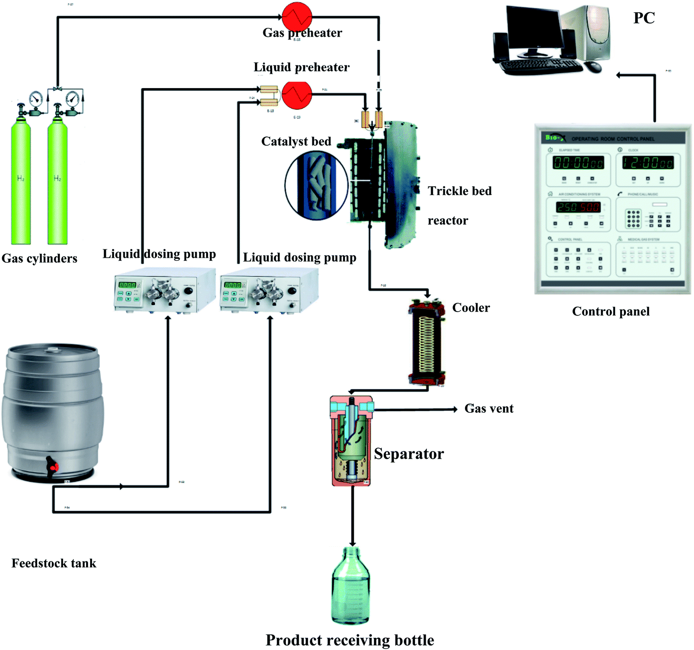
The evaluation of the effectiveness of the nanocatalyst prepared in Section 2.1 was conducted in a TBR unit shown in Fig. 1. A diesel fuel (Table S2†) was used as a feedstock to the TBR. A 3000 ppm of DBT (99% purity, Sigma Aldrich) was added to the feedstock as an organic sulfur model compound. Excess hydrogen gas (99.999% purity, Sigma Aldrich) was flown continuously to hydrotreat the diesel fuel. The specifications of the TBR unit are shown in Appendix I.† The main part of the TBR unit is the tubular reactor, which is loaded with the pelletized nanocatalyst particles. Before running the evaluation experiments, the catalytic bed was maintained at 140 °C for one hour to get rid of any moisture or remnant gases. The catalyst bed was reduced by flowing excess hydrogen at 250 °C for 4 hours. Also, the bed was sulfided by flowing sour diesel fuel 200 °C for 5 hours. Then, the evaluation experiments were conducted by flowing the feedstock, the diesel fuel, through the reactor via a dosing pump at the desired operating conditions, as shown in Table S3.† The product samples were withdrawn after flowing through the separator, and the TBR unit was off according to a safe shut down procedure. The conversion of the DBT was calculated by measuring the unconverted concentration of DBT in the sample of the product in a JASCO HPLC system device (UV-1575 UV/Vis Detector, Japan).
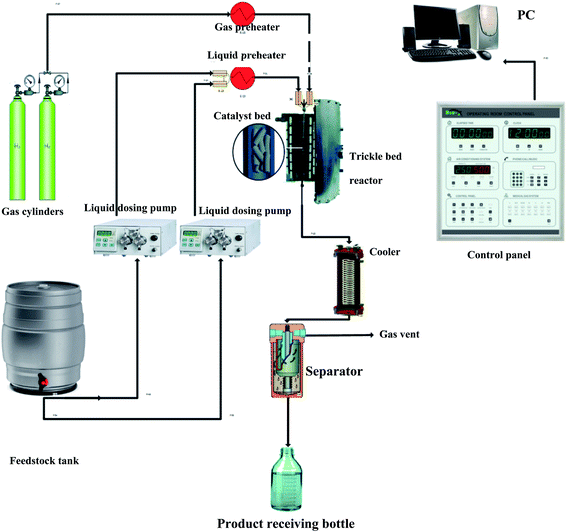 |
| | Fig. 1 Experimental setup of the HDS unit. | |
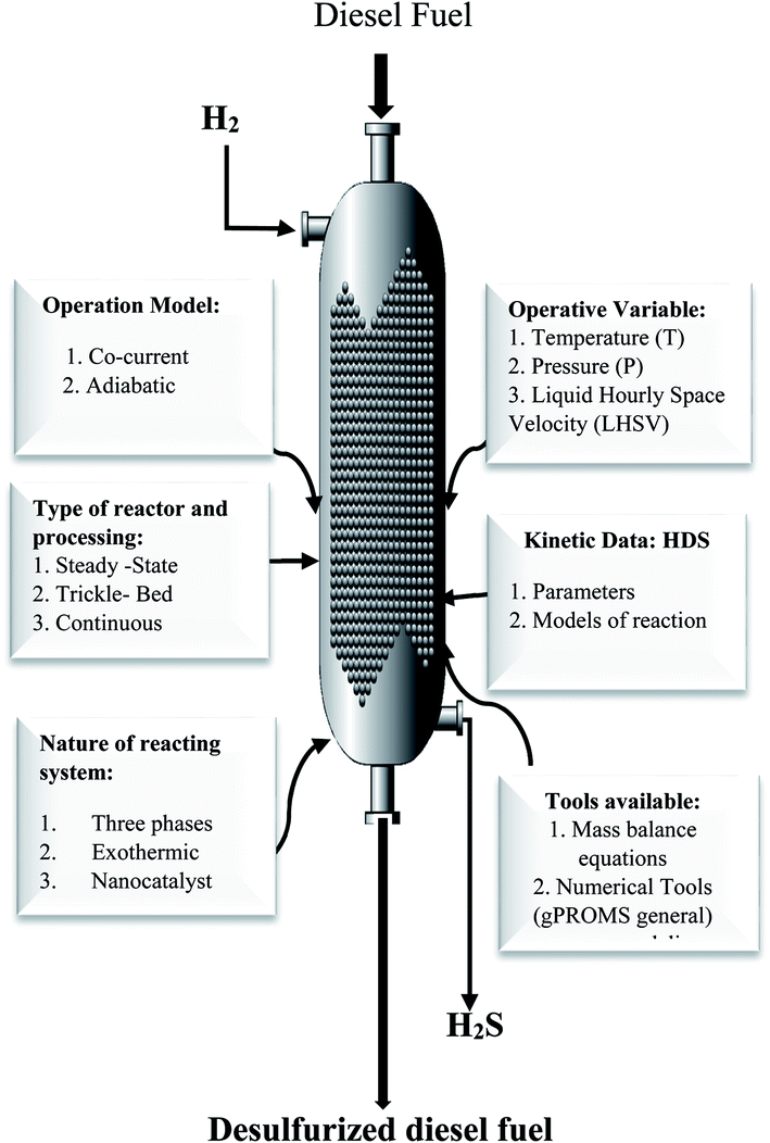
3. Mathematical modeling of the HDS process in TBR
To develop a comprehensive model for HDS over the prepared nanocatalyst in the TBR, several hypotheses were utilized in this investigation;
❖ The TBR unit operates at a steady-state.
(1) Excess pure hydrogen gas was used to minimize the resistance to bulk gas side convection mass transfer and approaches the hypothesis of hydrogen independent HDS reaction.
(2) The TBR operates at nonisothermal adiabatic conditions.
(3) In the reactor, all feedstock and the treated diesel fuel components are in the liquid form.
(4) Heterogeneous, one-dimension, with no axial dispersion operation.
(5) The external surface of the catalyst is partially wetted with the liquid feedstock, while complete wetting was assumed for the pores due to the capillary effect. Thus, the internal temperature gradients are negligible within the catalyst particles.
(6) The mild constant operating pressure was maintained at the time of the HDS reaction, and along the length of the TBR, there was marginal volatilization of the liquid fuel.
(7) The physical properties of the diesel fuel were kept constant at the time of the HDS reaction.
(8) For the energy balance along the reactor, the H2 and the feedstock mixture were assumed pseudo-homogenous so that they flow at the same temperature along the TBR.
(9) All transportation properties are cross-sectionally well defined and only differ with axial position and time.
Fig. 2 presents all data and process variables needed for developing the HDS process model and optimization of the process over the prepare nanocatalyst in the TBR.
 |
| | Fig. 2 Required data and available tools for modeling and optimization of the HDS process. | |
3.1 Mass balance equations
A mole balance was applied to the TBR for the HDS of the diesel fuel over the catalyst. The mole balance was based on the limiting reactant, the DBT as a model sulfur compound, at a steady-state as follow:| | | Input-output + consumption by reaction = 0 | (1) |
Inflow of DBT, moles per time = FDBT
Outflow of DBT, moles per time = FDBT + dFDBT
Consumption of DBT due to HDS, moles per time = (−rDBT)dV
Inserting the above terms into eqn (1) yields;
| | | FDBT = (FDBT + dFDBT) + (−rDBT)dV | (2) |
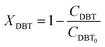
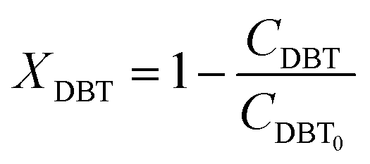
| | | dFDBT = d[FDBT0(1 − XDBT)] = −FDBT0dXDBT | (3) |
where,
CDBT: concentration of dibenzothiophene, moles per volume,
vL: volumetric flow rate, volume per time.
By replacement the following equation results:
| | | FDBT0dXDBT = (−rDBT)dV | (4) |
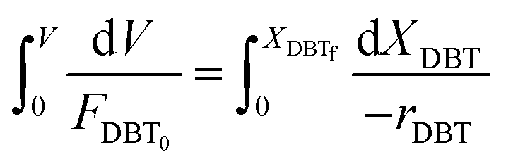
Eqn (4) shows the differential change of DBT conversion with the differential volume (dV) of the catalyst bed in the TBR. To obtain the relationship between reactor performance and the DBT conversion, eqn (4) should be integrated. For the molar rate and reaction speed they both are a function of DBT;
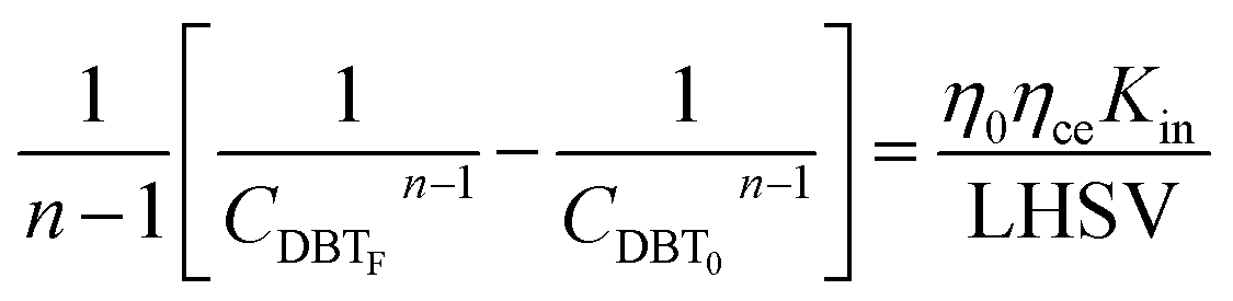
| | 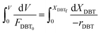 | (5) |
Thus
| | 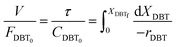 | (6) |
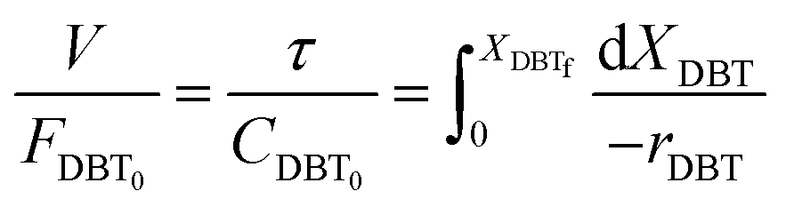
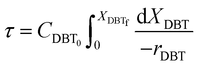
Alternatively:
| | 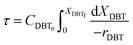 | (7) |
where:
| |  | (8) |
| |  | (9) |
| |  | (10) |
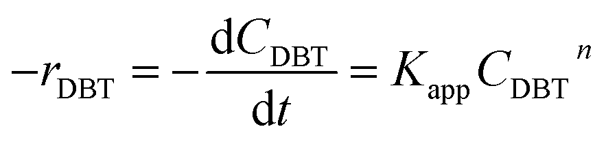
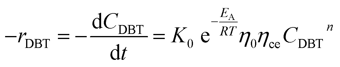
3.2 Chemical reaction rate
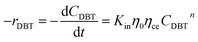
Mostly, to evaluate the catalyst in a laboratory-scale reactor and to calculate the apparent and intrinsic key variables of a chemical reaction rate, kinetic models can be used. According to relevant literature, several experimental techniques were utilized for the evaluation; filling up of the reactor bed with an inactive fluid, changing of catalyst weight of fluid flow rare to vary the space velocity, etc. For the HDS reaction discussed in the present study, it was assumed that the chemical reaction follows n-th order kinetics.| |  | (11) |
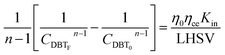
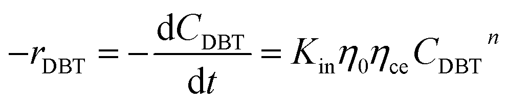
The apparent specific reaction rate was related to the intrinsic specific reaction rate with the accordance with internal diffusion and the hydrodynamics of the catalytic reactor as:14-
where internal diffusion is represented by (
η0) and the hydrodynamic by (
ηce),
η0: effectiveness factor of the prepared catalyst,
ηce: wetting efficiency of the external surface of the catalyst.
The chemical reaction may be produced:
| |  | (13) |
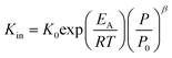
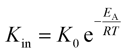
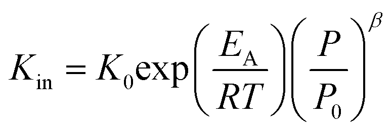
Using the modified Arrhenius equation (eqn (15)), the intrinsic basic reaction rate for HDS reaction (Kin) can be calculated for the reaction:
Arrhenius equation:
| |  | (14) |
The modified Arrhenius equation:
| |  | (15) |
where,
K0: pre-exponential factor or frequency factor (h
−1 (cm
3 mol
−1)
−1.1);
EA: activation energy of the HDS reaction (kJ mol
−1);
R: ideal gas constant (J mol
−1 K
−1);
T: absolute operating temperature (K);
P: operating pressure (psia);
Po: pressure reference (psia); and
β: order of pressure term.
Thus, the HDS reaction speed can be expressed by eqn (16);
| | 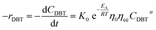 | (16) |
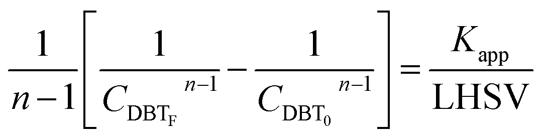
If the HDS reaction catalyzed by the nanocatalyst to eliminate the DBT follows the nth order kinetic substituting eqn (16) in (4) can be integrated to obtain the final expression as follows:
| | 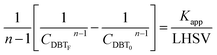 | (17) |
3.3 Reactor efficiency
The catalytic HDS reaction of DBT was conducted in a laboratory TBR at steady-state conditions. The HDS process involves numerous process parameters that contribute to mass, energy, and reaction events. Process parameters such as physical properties of the feedstock, hydrodynamics of the TBR, the feed rate of the feedstock, specific molar volumes of reacting gas and liquid, catalyst specifications, and the generated pressure gradient. To account for these parameters, appropriate correlations were used in this work.
Firstly, the apparent specific reaction rate was deployed with the hydrodynamic parameters of the TBR;
K
app = Kinf(hydrodynamics parameters). Could be rewritten as η0ηceKin which is used instead of Kapp.
| |  | (18) |
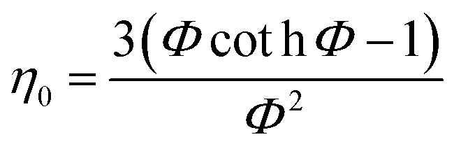
3.3.1 Nanocatalyst effectiveness factor (η0).
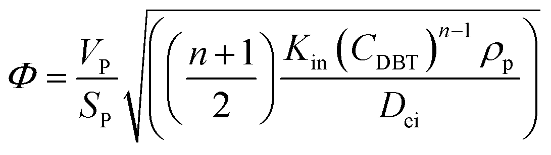
In general, the effectiveness factor (η0) depends on Thiele modulus (Φ), that is a specific catalyst shape property, and can be determined by the following relation assuming a perfectly spherical particle of the nanocatalyst:29,31| | 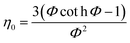 | (19) |
For the proposed nth-order HDS reaction, it was predicted that the Thiele modulus could be estimated by the normalized equation below :29,31
| | 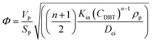 | (20) |
where,
VP: volume of the catalyst particle,
SP: total pore volume,
ρp: particle density.
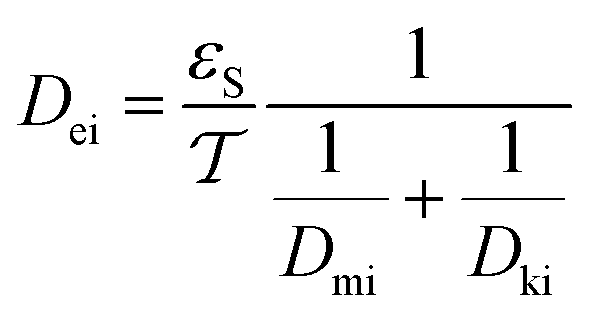
3.3.2 The effective diffusivity (Dei).
The effective diffusivity is a combination of the catalyst tortuosity and bed void fraction. The following equation was developed previously for the determination of the diffusivity:29,32| | 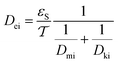 | (21) |
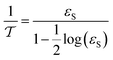
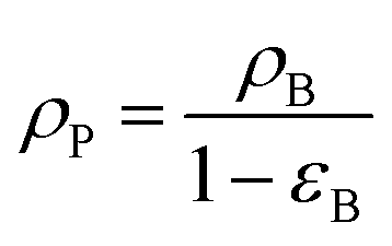
The nanocatalyst porosity (εS) can be determined based on experimental data that are using the following two equations| |  | (23) |
where, ρB: bulk density (gm cm−3), and Vg: pore volume (cm3 gm−1).
The pore network's tortuosity factor  is used in Dei measurement since the pores are not aligned from the surface to the center of the catalyst particle in the usual direction.30
| |  | (24) |
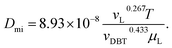
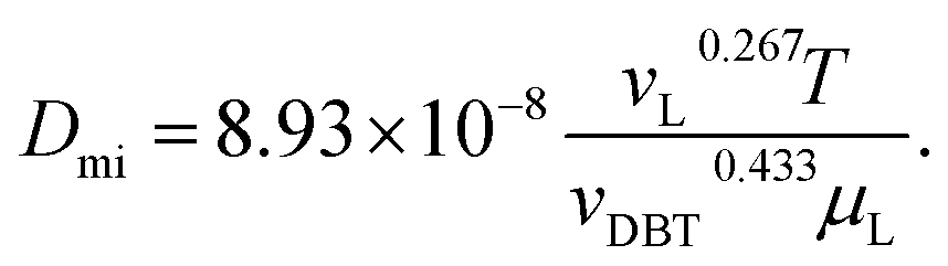
Inside the nanocatalyst particle, the effective diffusivity can be classified as molecular diffusivity (Dmi) and Knudsen diffusivity (Dki). The molecular diffusivity is calculated by Tyn–Calus equation:33,34
| |  | (25) |
The Knudsen diffusivity is calculated as follows:
29,31| | 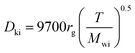 | (26) |
where,
rg: mean pore radius (cm); and
Mwi: molecular weight of DBT.
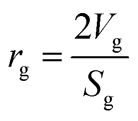
Mean pore radius:35
| |  | (27) |
where,
Vg: total pore volume (cm
3 gm
−1); and
Sg: specific surface area of the particle (cm
2 gm
−1).
Molar volume.
The molar volume of DBT is calculated by the following equation:34-| | | vDBT = 0.285(vcDBT)1.048 | (28) |
vcDBT: the critical volume of DBT.
The critical specific volume of liquid (diesel fuel) is estimated by a Riazi-Daubert correlation:36
vcL: the critical volume of diesel fuel.
| | | vcL = (7.5214 × 10⁻³(TmeABP)0.2896(ρ15.6)−0.7666)MWL | (30) |
where,
TmeABP: mean average boiling point, MW
L: the molecular weight of the liquid phase,
ρ15.6: density of diesel fuel at 15.6 °C.
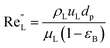
Wetting efficiency (ηce).
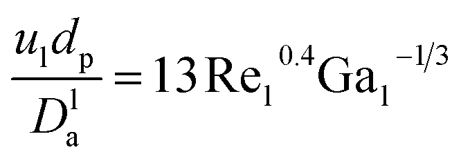
The catalyst wetting efficiency of the external catalyst surface (ηce) can be estimated at atmosphere pressure using the correlation as follows:47| | | ηce = 1.617ReL0.146GaL−0.071 | (31) |
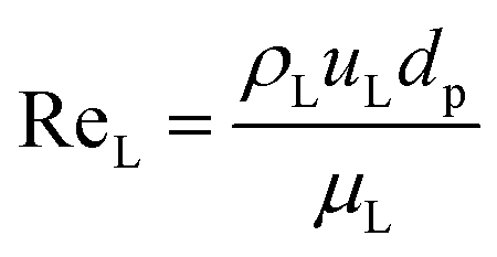
Reynolds number:
| |  | (32) |
Modified Reynolds number:
| |  | (33) |
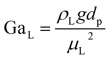
Galileo number:
| |  | (34) |
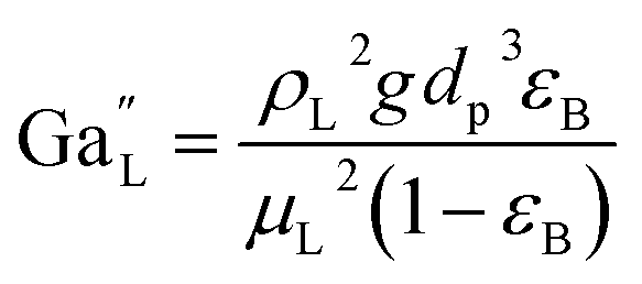
Modified Galileo number:
| |  | (35) |
where,
ρL = liquid density (gm cm
−3);
uL = liquid velocity (cm s
−1);
dp: particle diameter (cm);
g: acceleration (cm
2 s
−1);
εB: catalyst bed void fraction or catalyst bed porosity (—); and
μL: liquid viscosity (Pa s).
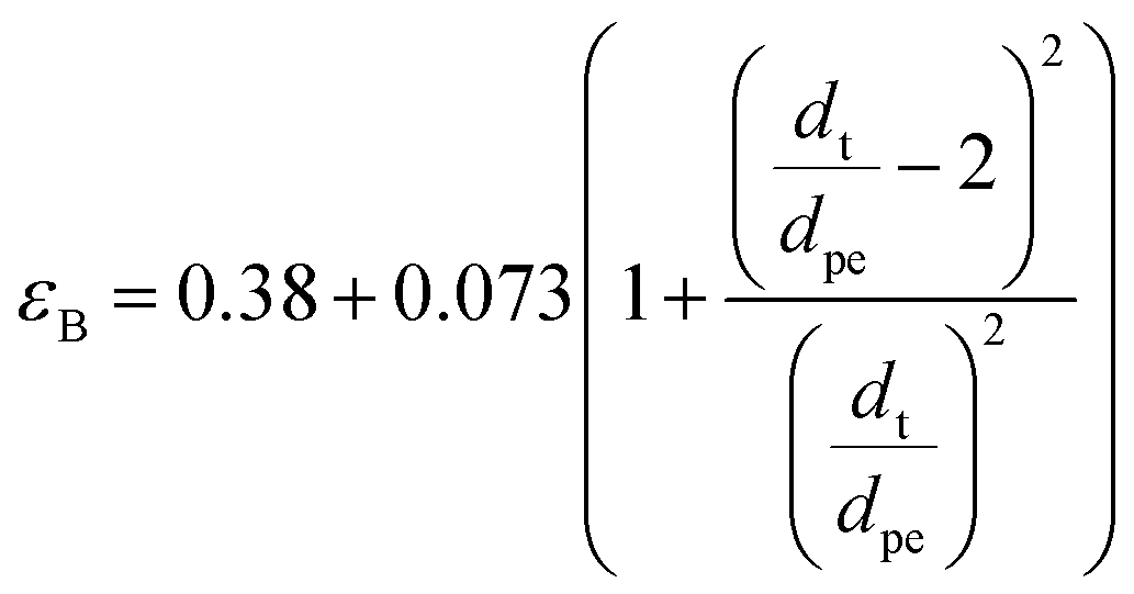
Bed void fraction (εB).
Bed void fraction (or bed porosity) can be calculated as follows for HDS catalyst beds:14,31,38,48| | 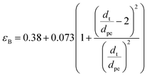 | (36) |
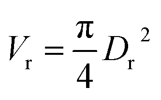
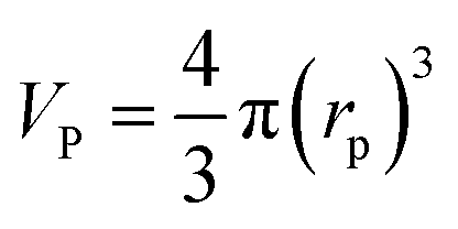
Particle effective diameter (dpe), defined as the diameter of a sphere with the same exterior surface or volume as the actual particle catalyst. Complete volume (Vp) and Catalyst surface area (Sp) The overall volume and surface area of the catalyst can be determined by particle form:
Assume a spherical shape
| |  | (37) |
Density.
The Standing-Katz equation estimates the density of diesel fuel as a function of temperature and pressure:49
Pressure depended on liquid density represented by the following equation:
| |  | (40) |
where,
P: pressure (psia);
ρ0: density of diesel fuel at 15.6 °C and 101.3 kPa.
In the equation below the temperature used to fix the liquid density:
| | | ΔρT = (0.0133 + 152.4(ρ0 + ΔρP)−2.45) (T − 520) − 8.1 × 10⁻⁶ − 0.0622 × 10−0.764(ρ0 + ΔρP))(T − 520)2 | (41) |
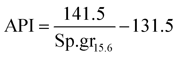
Viscosity.
It is appropriate to measure the viscosity of diesel fuel by using Glaso's equation:50-| | | μL = 3.141 × 10¹⁰(T − 460)−3.444[log10API]a | (42) |
where, API: american petroleum institute; a: dimensionless number;| | | a = 10.313[log10(T − 460)] − 36.447 | (43) |
T: temperature in (°R)| | 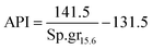 | (44) |
Sp.gr15.6: the specific gravity of diesel fuel at 15.6 °C.
3.4 Design of commercial-scale reactor
In this work, we are designing the industrial trickle bed reactor contains a total capacity of 2492 m3 perday of diesel fuel. The operation conditions estimated 350 °C, 10 bar, LHSV = 2 h−1, and initial concentration of DBT 2850 ppm.
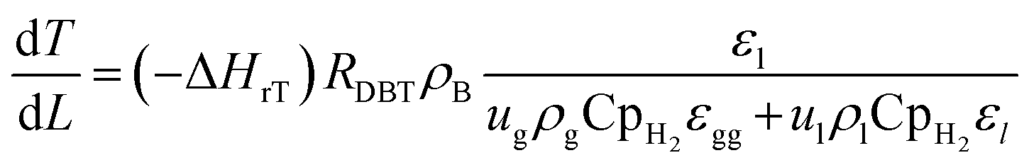
3.4.1 Energy balance.
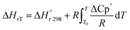
High temperatures include kinetics and reaction thermodynamics performed in trickle bed reactors.12 Under non-isothermal-adiabatic settings, industrial oxidation reactors run, and the reactions are generally exothermic. The mean reactor temperature will also rise along the catalyst's course. In other words, these reactors frequently run under the same conditions as those seen in industrial units but sustain the isothermal mode of operation (constant temperature of reaction). The heat balance for modeling small-scale reactor systems may also be omitted. This is used to predict the real efficacy of commercial trickle bed reactors using experimental knowledge from small reactors.39 The nonisothermal behavior along the catalyst bed within the industrial trickle bed reactor is explained by a heat balance equation51 as:| | 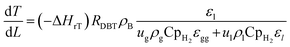 | (45) |
ΔHrT: the heat of reaction at temperature T, J mol−1, CpH2: heat capacity of hydrogen, J mol−1 K−1, CpDBT: heat capacity of dibenzothiophene, J mol−1 K−1, εgg: gas-phase fraction, (−).| | 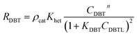 | (46) |
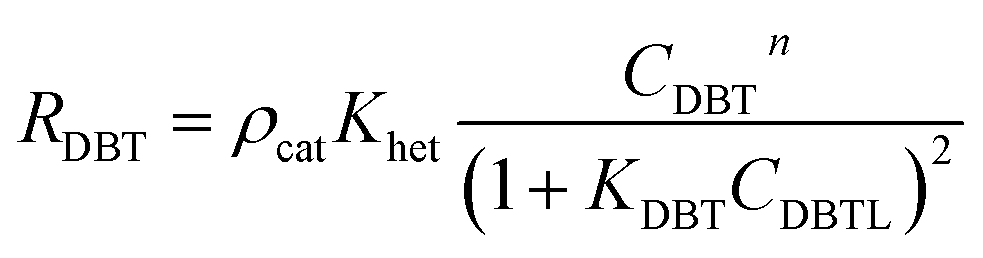
ρcat: catalyst density, g cm−3, Khet: apparent reaction rate constant, (mol cm−3)1−n s−1, KDBT: adsorption equilibrium constant of dibenzothiophene, cm3 mol−1, n: order of dibenzothiophene concentration, (—).
The adsorption equilibrium constant of dibenzothiophene (KDBT) can be evaluated by the following equation:52
| | KDBT = 2.0![[thin space (1/6-em)]](https://www.rsc.org/images/entities/char_2009.gif) exp(6.0 × 10⁶/RT) exp(6.0 × 10⁶/RT) | (47) |
T: temperature, K.
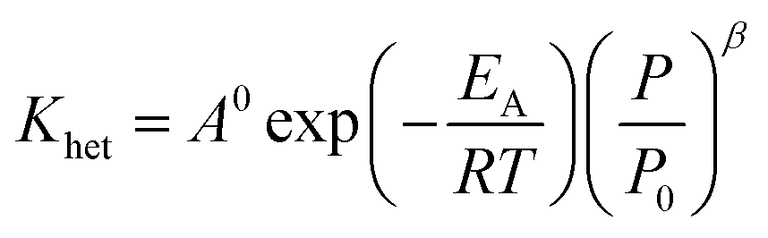
The reaction rate constant (Khet) can be described by Modified Arrhenius equation as follow:
| | 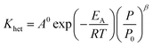 | (48) |
EA: activation energy, J mol
−1 K
−1,
A0: pre-exponential factor, (mol cm
−3)
1−n s
−1,
R: gas constant, J mol
−1 K
−1.
The heat potential of liquid phenol (including CpDBT) and hydrogen gas (including CpH2) can be determined by the following relationships as a function temperature;53
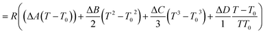
| | | CpDBT= 123.8 + 0.4215 × T | (49) |
| | | CpH2= 3.249 + 0.000422 × T + 8300/T2 | (50) |
T: absolute temperature, K.
The gas-phase fraction (εgg) can be measured according to the fraction of the bed void and the fraction of the liquid phase:39
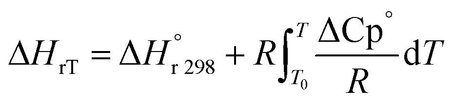
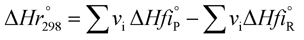
The heat of reaction (Δ
HrT) for the phenol oxidation is calculated
54 for the following reaction as follows:
| | | C12H8S + 2H2 → C12H10 + H2S | (52) |
| |  | (53) |

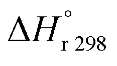
: heat of reaction at standard temperature (298 K), J mol
−1 K
−1.
The heat of reaction at standard temperature can be calculated as;
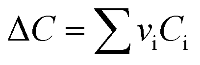
| | 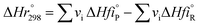 | (54) |
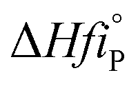
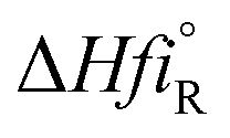
vi: reactant and product stoichiometric coefficient in the chemical reaction equation, which is negative for the reactant and positive for the product.

,

: The heat of formation for products and reactants, respectively, kJ mol
−1 K
−1.The standards heat of formation for each component are listed in Table S4:
†54
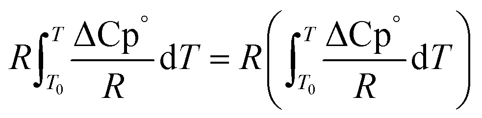
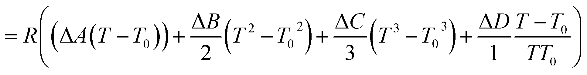
The second term of eqn (53) can be calculated as follow:
| | 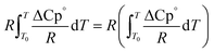 | (55) |
| |  | (56) |
| |  | (56a) |
| |  | (56b) |
| |  | (56c) |
| |  | (56d) |
Ai,
Bi,
Ci and
Di are constant values in heat capacities equation.
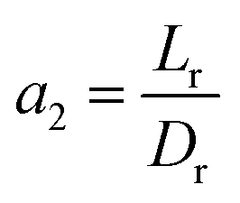
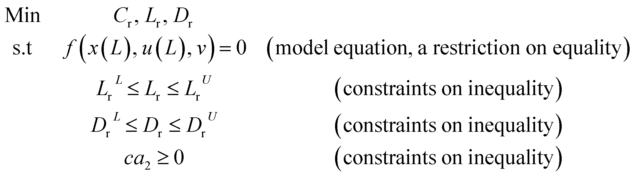
3.4.2 Optimal ratio of (Lr/Dr).
To eliminate the influence of radial dispersion, the optimal duration ratio of the reactor to reactor diameter must be sought. The problem of optimization can be described as:
| Introduced |
DBT, Catalyst, reaction temperature, Pressure, and LHSV |
| Determine |
Reactor length (Lr), and reactor diameter (Dr) |
| Minimizing the |
The reactor operating expenditure (Cr) |
| Are subjected to |
Method restrictions and linear limits (mentioned above) on all decision variables |
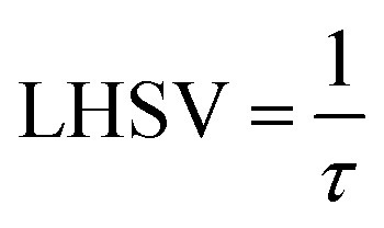
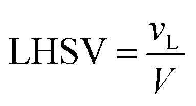
The volume of the reactor can be extracted from the liquid hourly space velocity (LHSV), as follows:
| |  | (57) |
vL: volumetric flow rate, m
3 h
−1; and
V: volume of catalyst, m
3| |  | (58) |
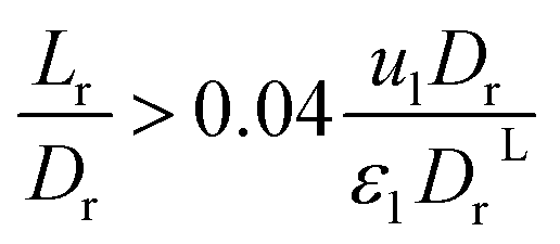
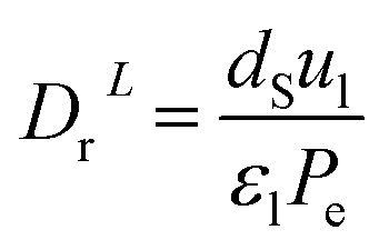
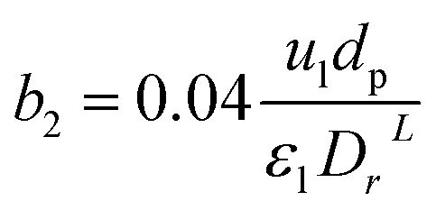
The effect of radial dispersion in a packed bed reactor dependent on the ratio of bed length (Lr) to reactor diameter (Dr) was overlooked as follows:55
| | 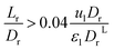 | (59) |
where,
Lr: bed length of the reactor (cm);
Dr: reactor diameter (cm);
ε1: liquid phase fraction;
DrL: radial mass dispersion coefficient (cm
2 s
−1);
ul: superficial liquid velocity (cm s
−1)
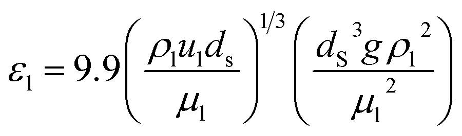
The percentage of the liquid phase can be determined from the following empirical relation:56.
| |  | (60) |
The coefficient of radial mass dispersion (DrL) can be derived from the following equation:56
| |  | (61) |
dS: the equivalent diameter of catalyst particle, cm,
Pe: Peclet number.
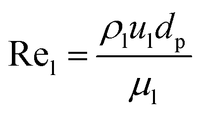
Peclet number depends on the operating system and reactor type (pilot plant or industrial reactor). The Peclet number can be calculated from the Sater–Levenspile connection for co-current activity with a commercial network, as stated by Meredos and Fabian:10
| | | Pe = 7.58 × 10⁻³Rel0.703 | (62) |
Re
l: Reynold number of the liquid phase, which estimated as follow:
| |  | (63) |
The capital cost (
Cr, $) of the reactor is increased by increasing the diameter and decreasing the length of the reactor, which can be estimated by the following equation as a function of
Lr and
Dr:
57| | 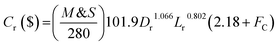 | (64) |
M&
S is Marshal and Swift index for cost escalation (
M&
S = 1536.5),
58FC,
Fm and
Fp are dimensionless factors that are function of the construction material and operating pressure (
Fm = 3.67,
Fp = 3.93).
58
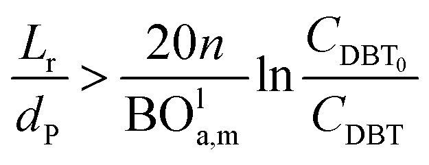
Effect of axial mass dispersion.
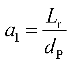
Continuing with radial mass dispersion, mass movement in the axial direction is still present.55 Still, it should be reduced by choosing an acceptable ratio of rector bed length to particle diameter (LrüdP) to eliminate any major deviations from the plug flow. Many studies have taken the observation of axial mass dispersion into account and its effect on the conversion.
Many values of Lr/dp have been studied in many of the literature, as shown in Table S5.†
Mederos and Fabian59 developed one of the parameters used commonly in design based on the minimum bed length needed to ignore axial dispersion or back mixing effects on the behavior of three-phase reactors as shown in eqn (66):
| | 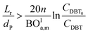 | (66) |
dP: The diameter of the catalyst particle, cm,
n: order of DBT concentration,
CDBT0: initial concentration of dibenzothiophene, mol cm
−3,
CDBT: the concentration of dibenzothiophene, mol cm
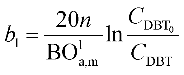
−3, BO
la,m: Bodenstein number for liquid phase, (—).
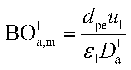
Bodenstein number (BOla,m), can be estimated by eqn (67):59
| |  | (67) |
Dla: overall axial dispersion coefficient, cm
2 s
−1,
dpe: equivalent diameter particle of catalyst, cm.
Two parameters are also represented and calculated a1 and b1, as follows:
| |  | (68) |
| |  | (69) |
| |  | (71) |
| |  | (72) |
Axial dispersion coefficient (
Dla) can be calculated by
eqn (74):
60| |  | (74) |
Dla: overall axial dispersion coefficient, m
2 s.
−1, Re
l: Reynold number of a liquid phase, (—), Ga
l: Galileo number of the liquid phase, (—).
The problem of optimisation may be written as:
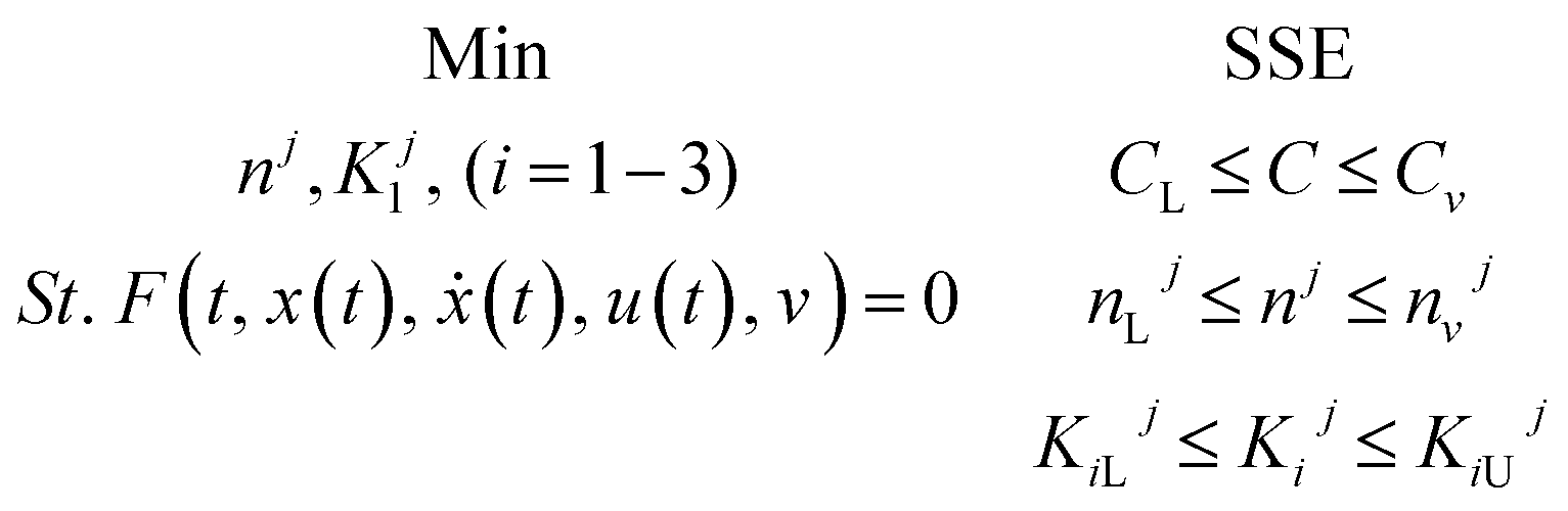
3.4.3 Optimization of HDS kinetic parameters.
The formulation of the optimization question for the HDS method parameter estimation can be described as follows:
| Introduced |
Configuration of reactor, catalyst, and conditions of the process |
| Determine |
First approach: maximizing the reaction order (n) and the reaction rate constant (k) at each temperature, and then using linear regression to measure the activation energy and pre-exponential component to the Arrhenius equation. On the second approach: it simultaneously measures the order of reaction (n), activation energy (E), and pre-exponential factor (Ko) |
| To minimize |
The sum of squared error (SSE) |
| Subjected to |
Limits and vector limits on all process optimization variables |
The problem of optimization can be defined as follows: using linear regression mathematically
where,
f(
t,
x(
t),
ẋ(
t),
u(
t),
v) = 0: display the method model which was previously introduced.
T (independent variable) is the response rate. The judgment predictor is
u(
t).
x(
t) represents all algebraic variables and differential variables. Symbol (
t) is the derivative of time-related differential variables. The variable architecture is
v.
C,
CL,
CU are lower bound and upper boundary concentrations. L and U are bounded lower and upper.
The optimization solution approach by gPROMS61 is carried out by two phases which can be summarized as follows s:62,63
(1) It carries out a simulation that converges all the equality constraints stated in (f) function and satisfies the inequality limitations.
(2) Perform optimization (decision variables values such as kinetic parameters that can be updated).
The challenging task in experiment-based model development is parameter estimation. The equilibrium values of the kinetic parameters are calculated by the statistical model reducing the error between the experimental data and the expected data.62
In the present work, two methods are used to determine the best kinetic parameter values and operating conditions for the trickle bed reactor based on the sulfur content in the oxidation cycle under specific operating conditions. Those methods are as follows:
First.
Linear regression: it calculates the reaction order (n) and the reaction rate constant (k), then uses the Arrhenius equation linear regression to measure the energy activation (E) and the pre-exponential constant (ko).
Second.
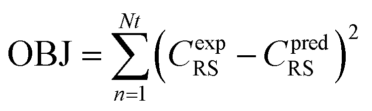
Nonlinear regression: specifically assessing the order of reaction (n), the activation energy (E), and the pre-exponential variable (ko). The following objective function was optimized to approximate optimal value of kinetic parameters, as seen below:| |  | (75) |
In eqn (75), Nt represents the number of tests, the experimental concentration, and the sulfur model's expected concentration, respectively.
4. Results and discussion
4.1 Experimental results
According to BET analysis, the characteristics of the homemade 3.5%Co, 11.2% Mo Co–Mo/γ-Al2O3 nanocatalyst are shown in Table S6.† It can be seen from this Table that after the nano support impregnation with Co and Mo, the pore volume and surface area were reduced. This reduction owes to the occupation of the vacant sites of the support. However, both surface area and pore volume are still high compared to previous works.64–66 The FEME, XRD and BET analyses of the prepared catalyst were described elsewhere.67
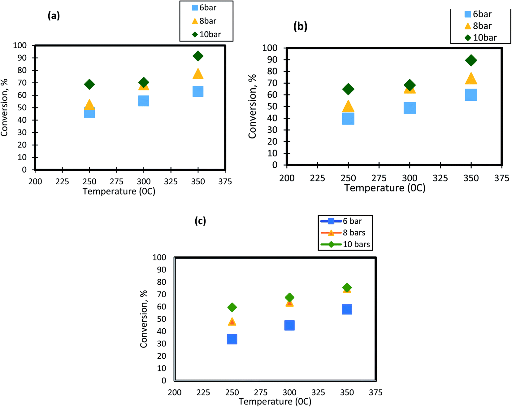
4.1.1 Influence of reaction temperature on the conversion of DBT.
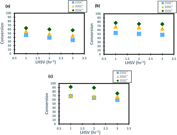
For HDS reactions, it is well known that the operating temperature has a significant impact on DBT conversion. In the present study, the effect of reactor temperature was studied at different levels( 250 °C, 300 °C, and 350 °C). It can be seen from Fig. 3 that as the temperature of HDS reactions was raised from 250 °C to 300 °C; the DBT conversion increases from 45.65% to 55.4% at 6 bar and 1 h−1. The same behavior was observed at the other operating conditions. To following clarifications explain the observed DBT response to temperature change:
 |
| | Fig. 3 Effect of temperature on the process conversion of DBT for different pressures and (a)1 h−1 (b) 2 h−1 (c) 3 h−1. | |
(1) Temperature increase means that the number of molecules involved in the hydrogenation reaction will rise as the activation energy decreases. Diffusion and osmosis in the pore nanocatalysts increase with temperature.68 Temperature increase would also have an impact on the physical properties of a highly effective liquid feedstock. Henry's constant and disperse consistency will increase while the viscosity and surface tension will decrease. Throughout this way, temperature and working pressure facilitated the rate of absorption of molecular hydrogen throughout diesel fuel, the rate of diffusion of DBT molecules, and the rate of dissolution.51,69
(2) As the temperature increases between 300 °C and 350 °C (the maximum boiling point is 357 °C), the phase transition from liquid to DBT vapor happens. Thus, the conversion of the sulfur compound increases as the gas molecules has a high rate of diffusion within the pores of the catalyst.70
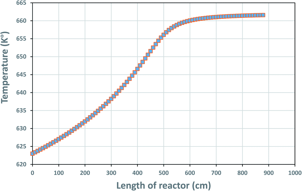
The temperature profile along the reactor length is shown in Fig. 4, reflecting on the energy balanced applied on the TBR in part 3.4.1.
 |
| | Fig. 4 Temperature profile along the reactor bed length. | |
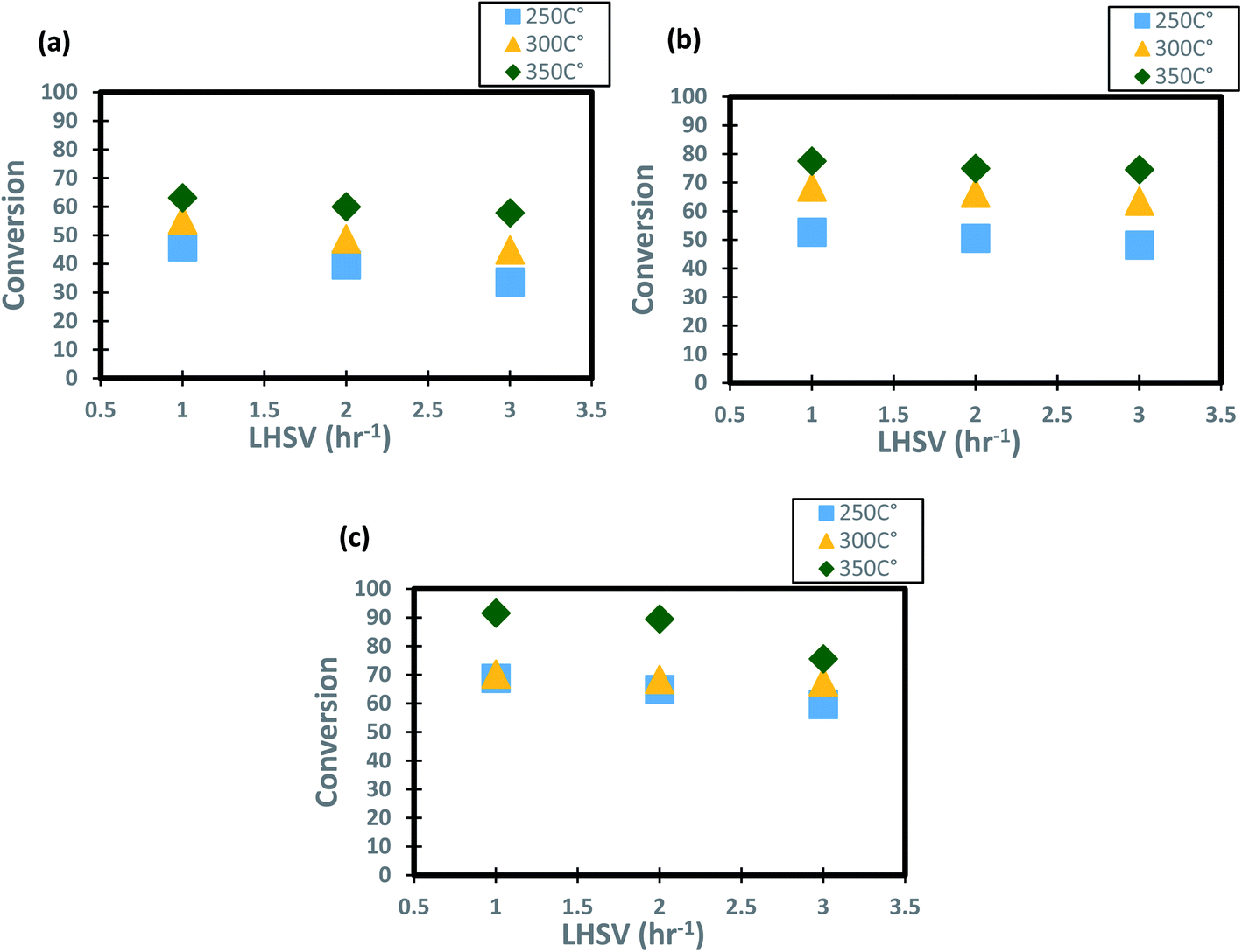
4.1.2 Influence of the diesel fuel liquid hourly space velocity on the conversion of DBT.
The profiles of DBT conversion versus diesel fuel hourly space velocity were obtained in the present study, as shown in Fig. 5. These profiles were obtained at different temperatures (200–350 °C) and operating pressures (6–10 bar) via the HDS in the TBR unit with the homemade nanocatalyst. It was found that running the HDS process at low diesel fuel space velocity promoted the DBT conversion on Co–Mo on gamma-alumina nanocatalyst in the HDS of diesel fuel.67 For Fig. 5, it was observed that the increase of space velocity resulted in a significant decrease in DBT conversion at all operating pressures and temperatures. The decrease was caused by the insufficient time of contact between the reactants on the surface of the nanocatalyst.16,71. A minimal reaction of DBT occurred due to the narrow pores of the nanocatalyst involving high-pressure activity to drive hydrogen and feedstock through the pores of the catalyst. Also, at LHSV = 3 h−1 and 6 bar, the conversion of DBT was decreased. Given the results obtained, the optimum LHSV for the HDS reaction of DBT was 3 h−1, which is the maximum conversion of DBT, 91.4%, obtained at LHSV = 1 h−1, 350 °C and 10 bar (Fig. 5 c). Nevertheless, the conversion will not undergo a substantial decrease because LHSV improved to 2 h−1, retaining 89.4% at 10 bar and 350 °C as high-temperature activity allowed the chemical reactions of hydrogen and diesel fuel and reduced the effect of LHSV. The same pattern was noticeable at low hydrogen pressures of 8 bar and 6 bar, where the gap in DBT conversion was important at 350 °C and specific LHSVs, as they were 74–77% and 57–63% respectively.
 |
| | Fig. 5 Effect of liquid hourly space velocity on the process conversion of DBT for different temperatures and (a) 6 bar (b) 8 bar (c) 10 bar. | |
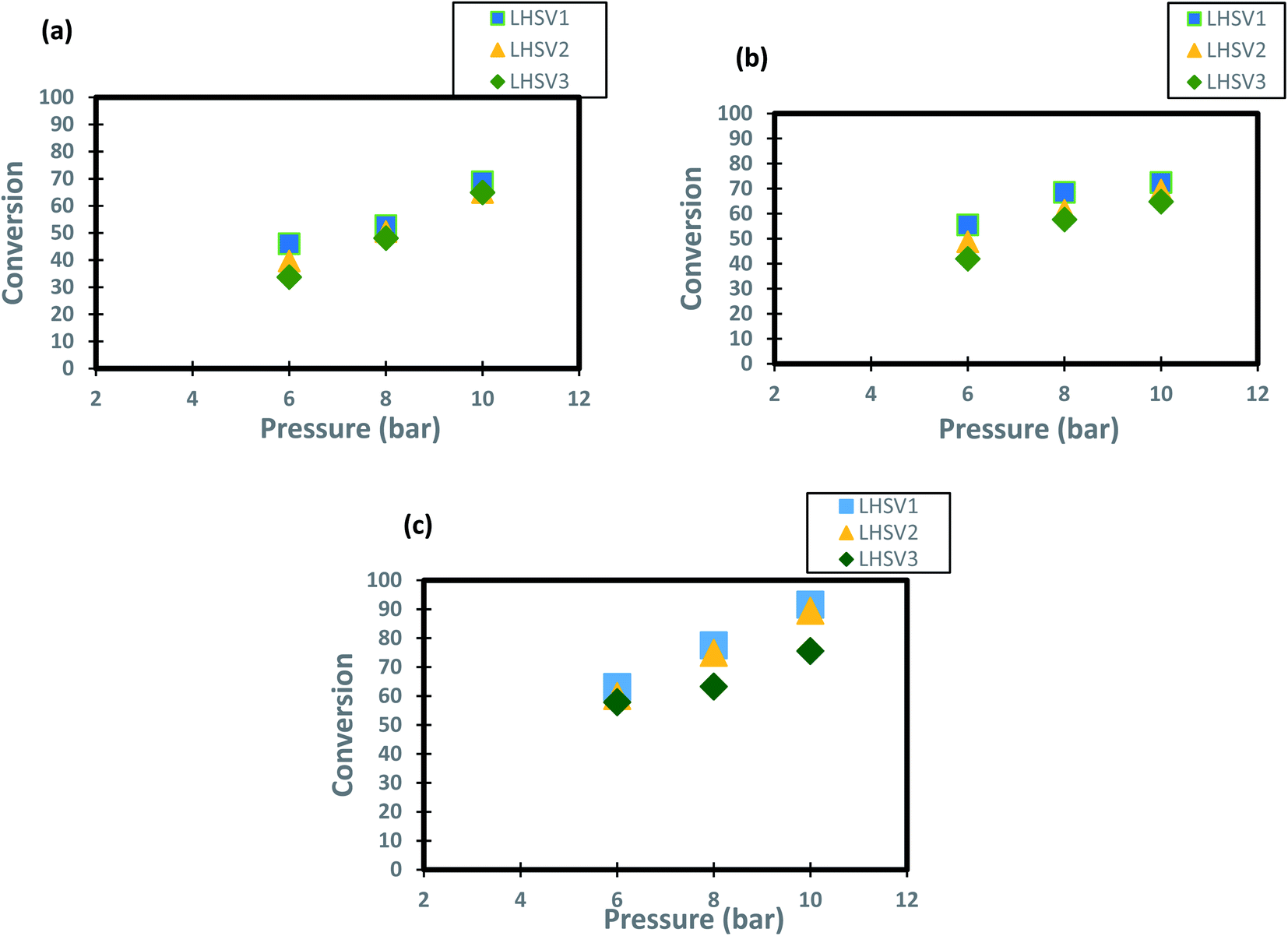
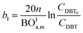
4.1.3 Influence of pressure on the conversion of DBT.
The operating pressure has a reported effect on three-phase reactions.18,72,73 In the present study, the trend of conversion of DBT change at different operating pressures (6, 8 and 10 bar) and LHSVs (1, 2 and 3 h−1) is shown in Fig. 6. It has been shown form these results that operation at high pressure of 10 bar and low flow rate of diesel fuel (low space velocity of 1 and h−1) enhanced the DBT conversion to greater than 90%. This enhancement caused by the influence of the operating pressure on HDS kinetics as the reaction becomes a liquid limited and the nanocatalyst performs better in the upflow TBR.74 For the low operating pressure (6 bar) and a high liquid hourly space velocity of 3 h-1 the DBT conversion decreased to less than 80% at all operating temperatures because the HDS reaction became limited by the flow of hydrogen gas. This enhancement of DBT conversion is more obvious at the highest operating temperature of 350 °C because the physical properties of diesel fuel as the physical properties were all changed and made contact with the hydrogen gas on the nanocatalyst more efficient for HDS reaction. As a result, an improvement of 57% to 89.4% was observed when the operational pressure rose from 6 to 10 bar at 1 h−1 and 350 °C, which is supposed to be attributed to the size of the catalytic pores that are packed with a wide amount of hydrogen required for DBT conversion. Compared to the traditional Co–Mo catalysts, significant advances have been made but at a far higher hydrogen pressure of 25–35 cm.16,75.
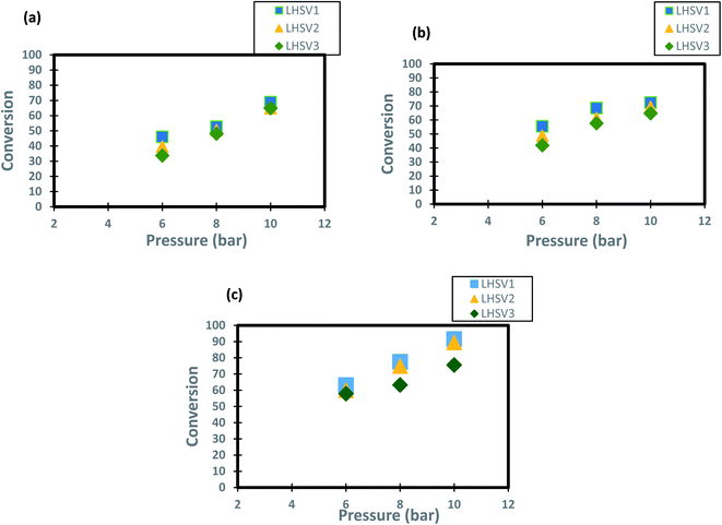 |
| | Fig. 6 Effect of hydrogen pressure on the process conversion of DBT for different LHSVs and (a) 250 °C (b) 300 °C (c) 350 °C. | |
4.2 Estimation of kinetic parameters of the HDS process
The values used in the HDS models for the constant parameters are given in Table 1. The kinetic parameters produced through the HDS process optimization technique are shown in Table 2. Fig. 7 shows a comparison of the experimental and simulated values of all lumps obtained according to the optimization results. Deviations between both the experimental and simulated values are up to 5%.
Table 1 Values of constant parameters used in the HDS models
| Parameter |
Value |
| Temperature (T), K |
T
1 = 523.15, T2 = 573.15, T3 = 623.15 |
| Pressure (P), psia |
P
1 = 88.2, P2 = 117.6, P3 = 147 |
| Liquid hour space velocity (LHSV), h−1 |
LHSV1 = 1, LHSV2 = 2, LHSV3 = 3 |
| Initial concentration (C), wt% |
0.2850 |
| Density (Deno) of diesel fuel (15.6 °C and 101.3 kPa), g cm−3 |
0.8333 |
| Gas constant (R), J mol−1 K−1 |
8.314 |
| The volume of catalyst particle (Vp), cm3 |
4.74 × 10⁻¹⁷ |
| The total geometric external area of the particle (Sp), cm2 |
6.3328 × 10⁻¹¹ |
| Bulk density (bulk), g cm−3 |
1 |
| Pore volume per unit mass of catalyst (Vg), cm3 g−1 |
0.041926 |
| The molecular weight of gas (Mwi), g mol−1 |
4 |
| The molecular weight of LGO (MWL), g mol−1 |
184.26 |
| The critical specific volume of the DBT compound, cm3 mol−1 |
232900 |
| Mean average boiling point, K |
540 |
| The specific surface area of the particle, cm2 g−1 |
435000 |
| Tube diameter, cm |
2.5 |
| Velocity of diesel fuel |
u
L1 = 15.653, uL2 = 38.522, uL3 = 61.488 |
| Acceleration gravity |
981 |
Table 2 Optimal model parameters obtained by the optimization process
| Parameter |
Value |
Unit |
|
K
1@T1, P1 |
1.31 |
h−1 (cm3 mol−1)1.1 |
|
K
2@T2, P1 |
1.48 |
h−1 (cm3 mol−1)−1.1 |
|
K
3@T3, P1 |
3.22 |
h−1 (cm3 mol−1)−1.1 |
|
K
4@T1, P2 |
1.81 |
h−1 (cm3 mol−1)−1.1 |
|
K
5@T2, P2 |
3.44 |
h−1 (cm3 mol−1)−1.1 |
|
K
6@T3, P2 |
5.10 |
h−1 (cm3 mol−1)−1.1 |
|
K
7@T1, P3 |
3.11 |
h−1 (cm3 mol−1)−1.1 |
|
K
8@T2, P2 |
3.88 |
h−1 (cm3 mol−1)−1.1 |
|
K
9@T3, P3 |
11.56 |
h−1 (cm3 mol−1)−1.1 |
|
N
|
2.1 |
— |
|
B
|
0.0168 |
— |
|
E
A
|
40.535 |
kJ mol−1 |
|
K
o
|
26 × 1010 |
h−1 (cm3 mol−1)−1.1 |
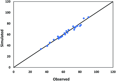 |
| | Fig. 7 Comparison between observed and predicted conversion of DBT. | |
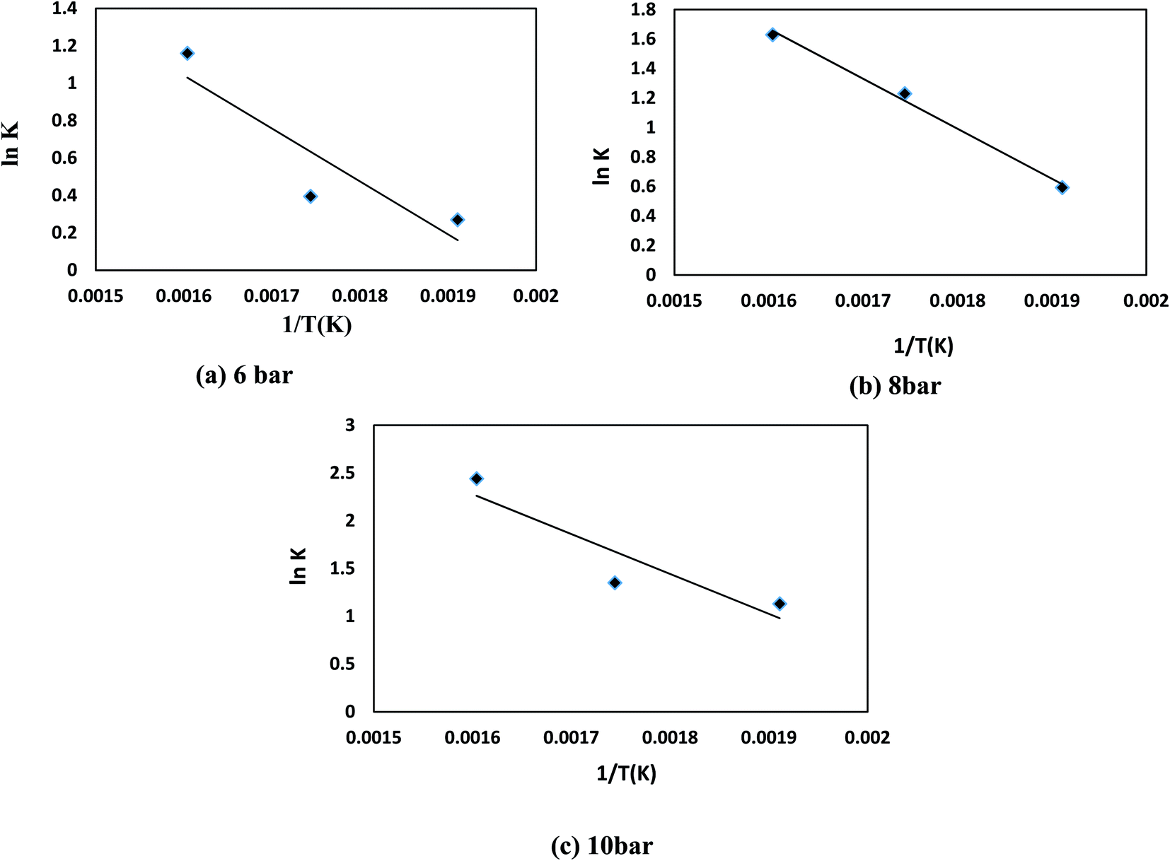
To approximate the activation energy defined in eqn (15), a plot of (lnK) versus (1/T) shows a straight line with a slope equivalent to (−EA/R) from which the activation energy is estimated, as seen in Fig. 8. Many variables influence the activation energy; one of these variables is the form of a trigger that is known to be the essential element. For comparison, DBT's activation energy obtained from two catalyst forms (MoS2 and CoMo/Al2O3) and tested at the same operating conditions in a previous study was 79.002, 43.89 kJ mol−1, respectively.75 The second element determining the activation energy is the volume of solvent used, the activation energy of DBT was 108.68 and 112.86 kJ mol−1 under the same operating conditions as previously tested in two separate forms of diesel fuel over the same volume of CoMo/Al2O3 catalyst.75 The third element is the form of sulfur product, which is an individual or total sulfur since total sulfur HDS has much higher activation energy than the individual. The total sulfur activation energy for diesel fuel was stated to be 119.966 kJ mol−1 (ref. 76) based on sulfur compound contents in oil. The activation energy thus depends on the form of catalyst, the amount of feed solvent, and the type of the sulfur compound. For the homemade nanocatalyst, the activation energy obtained was 40.535 kJ mol−1 for the HDS of DBT. The order of the reaction for hydrogen gas was (0) for HDS of DBT, which agrees with the assumption in Section 3, because of the little effect of changing hydrogen pressure gas.77,78 The efficacy factor was also measured according to the model adopted in the gPROMS analysis and found to be equivalent to one, which is a good indicator of the nanocatalyst's outstanding activity. The results also showed high values of wetting efficiency; this indicates a complete wetting of the surface and thereby the high activity of the nanocatalyst. The optimum value obtained was 86% at 350 °C, 10 bar, and 1 h−1.
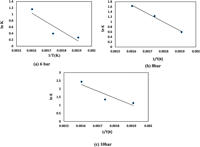 |
| | Fig. 8 ln(K) versus 1/T kinetic for HDS of DBT for (a) 6 bar (b) 8 bar (c) 10 bar. | |
The reaction rate and mathematical kinetic models for HDS of DBT were as follow:
| |  | (76) |
| |  | (77) |
4.3 Optimal parameters
The following case studies will be investigated here related to the design of the industrial TBR for HDS of DBT:
Case 1: The capital cost of the reactor (Cr, $) depends on the Lr/Dr ratio (in terms of a2). Where the capital cost of the reactor increases by increasing the diameter and decreasing the length of the reactor. Also, the radial dispersion (DR) can affect the process conversion related to the ratio of height to the diameter of the reactor. In this case, to avoid the effect of radial dispersion and to obtain high conversion with minimum cost, optimal values of a2 and b2 with the capital cost of the reactor were calculated and optimized with gPROMS.
Case 2: There is a wide range of Lr/dp values, as observed by Mederos et al.59. To neglect the effect of axial dispersion (DA), the best values of a1 and b1, process simulation parameters, were applied in the simulation process to check the best value of the ca1 parameter, which represents the difference between a1 and b1. The results are shown in Table 3. It is found that a DBT conversion of 99% can be achieved in a commercial size TBR packed with 52 m3 of the nano catalyst at a processing capacity of 2492 m3 h−1.
Table 3 Optimal commercial trickle bed reactor parameters
| Decision variable type |
Optimized value |
|
a
2
|
3.265 |
|
b
2
|
0.6727104 |
|
ca
2
|
2.59229 |
|
L
r/Dr |
3.265 |
|
L
r (cm) |
890 |
|
D
r (cm) |
272.6 |
|
C
r ($) |
1901320 |
|
D
R (cm2 s−1) |
3.433035 × 10⁻¹⁰ |
| Conversion |
99% |
| The volume of catalyst (m3) |
52 |
| Flow (m3 per day) |
2492 |
|
a
1
|
2.289086 × 10⁸ |
|
b
1
|
891.2803 |
|
ca
1
|
2.289077 × 10⁸ |
|
D
A (cm2 s−1) |
1.773677 × 10⁻⁸ |
5. Conclusions
Due to the growing concerns and the structured regulations of emission to the environment, the present study was conducted to design a model for the nano-catalyzed HDS process in a trickle bed reactor. And the results of this review can be summarized as follows.
(1) A mathematical model is built and validated for that method. The kinetic parameter is calculated by decreasing the amount of square error between the experimental findings and those predicted. The average absolute error among all results was less than 5% at different conditions.
(2) To determine the HDS optimal kinetic parameters, two approaches to optimization techniques (linear and nonlinear method) can be used. It was noted that the second approach (nonlinear method) is more reliable compared to the first approach as many variables described by the model impacted DBT's HDS on Co–Mo nanocatalyst, and the relationship was complicated. In comparison, the optimization technique can be used with great confidence to achieve the high precision of the mathematical model.
(3) The optimal operating conditions in a commercial TBR to give process conversion of 91.57% and highest selectivity of DDS were: temperature 350 °C, pressure 10 bar, liquid hourly space velocity 1 h−1, and Lr/Dr = 3.265.
(4) The use of Co–Mo loaded on alumina nanoparticles enhanced the economic conversion of DBT into biphenyl via direct desulfurization over the undesired route of DBT into cyclohexylbenzene. Thus, less hydrogen is needed to implement the HDS process.
(5) The novel prepared Co–Mo nanocatalyst has been able to drastically reduce the fuel's sulfur content in a flow reactor, thereby delivering high-quality fuel with significantly reduced emissions to the environment.
Nomenclature
| BOla,m | Bodenstein number for liquid phase, (—) |
| Dla | The overall axial dispersion coefficient, cm2 s−1 |
|
D
r
| Bed diameter, cm |
|
D
r
L
| The radial mass dispersion coefficient, cm2 s−1 |
|
L
r
| Bed length, cm |
|
d
S
| The equivalent diameter of the catalyst particle, cm |
|
A
| Dimensionless number, — |
|
C
DBT
| Concentration of dibenzothiophene, cm3 mol−1 |
|
C
DBT0
| The initial concentration of dibenzothiophene, cm3 mol−1 |
|
C
in
| Initial concentration (inlet to the reactor), cm3 mol−1 |
|
C
out
| Final concentration (outlet from the reactor), cm3 mol−1 |
|
C
r
| The capital cost of the reactor, $ |
|
D
ei
| Effective diffusivity, cm2 s−1 |
|
D
Ki
| Knudsen diffusivity factor, cm2 s−1 |
|
D
mi
| Molecular diffusivity, cm2 s−1 |
|
d
p
| Particle diameter, cm |
|
d
pe
| Equivalent particle diameter, cm |
|
d
t
| Tube diameter, cm |
|
E
A
| Activation energy, kJ mol−1 |
|
F
DBT
| Input of dibenzothiophene, moles per time |
|
g
| Acceleration, cm s−2 |
|
K
| Reaction rate constant, h−1 per wt(n−1) |
|
K
app
| The apparent reaction rate constant, — |
|
K
in
| Kinetic rate constant, (time)−1 per (con.)1−n |
|
K
o
| Frequency or pre-exponential factor, cm3 g−1 s |
|
M
wi
| The molecular weight of oxygen, g gmol−1 |
| MWL | The molecular weight of the liquid phase, g gmol−1 |
|
n
| Order of reaction kinetic, — |
|
P
| Pressure, psia |
|
P
o
| Pressure reference, psia |
| ppm | Part per million |
|
R
| Universal gas constant, 8.314 J mol−1 K−1 |
|
r
DBT
| Rate of reaction dibenzothiophene, — |
|
r
g
| Mean pore radius, cm |
|
r
p
| Radius of particle, cm |
|
S
g
| The specific surface area of particle, cm2 g−1 |
|
S
P
| The external surface area of the catalyst particle, cm2 |
| Sp.gr15.6 | The specific gravity of oil at 15.6 °C, — |
|
T
| Temperature, K or °C |
|
T
meABP
| Mean average boiling point, R |
|
u
L
| The superficial velocity of the liquid, cm s−1 |
|
V
| Reactor bed volume, cm3 |
|
v
CDBT
| The critical specific volume of the DBT compound, ft3 mol−1 |
|
v
CL
| The critical specific volume of liquid, cm3 mol−1 |
|
v
DBT
| Molar volume of DBT at n.b. temperature, cm3 mol−1 |
|
V
g
| Total pore volume, cm3 g−1 |
|
v
L
| Molar volume of liquid at its n.b. temperature, cm3 mol−1 |
|
V
P
| The volume of the catalyst particle, cm3 |
|
V
P
| Pore volume, cm3 |
|
X
DBT
| Conversion of dibenzothiophene |
Greek letters
|
β
| Order of pressure term |
| Δρp | Pressure dependence of liquid density, lb per ft3 |
| ΔρT | Temperature correction of liquid density, lb per ft3 |
|
ρ
15.6
| The density of diesel fuel at 15.6 °C, g cm−3 |
|
ρ
B
| Bulk density, g cm−3 |
|
ρ
L
| Liquid density at process condition, lb per ft3 |
|
ρ
o
| The density of diesel fuel at 15.6 °C and 101.3 kpa, lb per ft3 |
|
ρ
p
| Particle density, g cm−3 |
|
ε
B
| Bed void fraction |
|
μ
L
| Dynamic viscosity of the liquid phase, mPa s |
|
ε
l
| Liquid phase fraction |
|
τ
| Residence time, h |
Conflicts of interest
There are no conflicts to declare.
Acknowledgements
This research was partially funded by Institute of International Education (IIE), USA.
References
- Q. Luo,
et al., Fast and deep oxidative desulfurization of dibenzothiophene with catalysts of MoO 3–TiO 2@ MCM-22 featuring adjustable Lewis and Brønsted acid sites, Catal. Sci. Technol., 2019, 9(21), 6166–6179 RSC.
- L. Kang,
et al., Oxidative desulfurization of dibenzothiophene using molybdenum catalyst supported on Ti-pillared montmorillonite and separation of sulfones by filtration, Fuel, 2018, 234, 1229–1237 CrossRef CAS.
- K. Zhao,
et al., Extractive desulfurization of dibenzothiophene by a mixed extractant of N, N-dimethylacetamide, N, N-dimethylformamide and tetramethylene sulfone: optimization by Box–Behnken design, RSC Adv., 2015, 5(81), 66013–66023 RSC.
- M. I. Ahmad, N. Zhang and M. Jobson, Integrated design of diesel hydrotreating processes, Chem. Eng. Res. Des., 2011, 89(7), 1025–1036 CrossRef CAS.
- S. A. Ali, Development of improved catalysts for deep HDS of diesel fuels, Appl. Petrochem. Res., 2014, 4(4), 409–415 CrossRef CAS.
- A. Alvarez,
et al., A modeling study of the effect of reactor configuration on the cycle length of heavy oil fixed-bed hydroprocessing, Fuel, 2011, 90(12), 3551–3560 CrossRef CAS.
- A. Alvarez and J. Ancheyta, Simulation and analysis of different quenching alternatives for an industrial vacuum gasoil hydrotreater, Chem. Eng. Sci., 2008, 63(3), 662–673 CrossRef CAS.
- A. Alvarez and J. Ancheyta, Modeling residue hydroprocessing in a multi-fixed-bed reactor system, Appl. Catal., A, 2008, 351(2), 148–158 CrossRef CAS.
- J. Ancheyta, M. S. Rana and E. Furimsky, Hydroprocessing of heavy petroleum feeds: Tutorial, Catal. Today, 2005, 109(1–4), 3–15 CrossRef CAS.
- F. S. Mederos and J. Ancheyta, Mathematical modeling and simulation of hydrotreating reactors: Cocurrent versus countercurrent operations, Appl. Catal., A, 2007, 332(1), 8–21 CrossRef CAS.
- H. Bao,
et al., Advance in kinetics model of diesel hydrodearomatization reaction, Chem. Ind. Eng. Prog., 2011,(5), 7 Search PubMed.
- G. Soto,
et al., Preparation of a Ag/SiO2 nanocomposite using a fluidized bed microwave plasma reactor, and its hydrodesulphurization and Escherichia coli bactericidal activities, Powder Technol., 2011, 213(1–3), 55–62 CrossRef CAS.
- G. Bollas,
et al., A Computer-Aided Tool for the Simulation and Optimization of the Combined HDS–FCC Processes, Chem. Eng. Res. Des., 2004, 82(7), 881–894 CrossRef CAS.
-
M. Al-Dahhan
Recent Advances and Scale-up of Trickle Bed Reactors for Energy and Environmental Applications, in Proceedings of the International Symposium on Advances in Hydroprocessing of Oil Fractions, ISAHOF 2007, 2007 Search PubMed.
- C. Bara,
et al., Surface Science Approaches for the Preparation of Alumina-Supported Hydrotreating Catalysts, ChemCatChem, 2015, 7(21), 3422–3440 CrossRef CAS.
- A. T. Jarullah, I. M. Mujtaba and A. S. Wood, Kinetic model development and simulation of simultaneous hydrodenitrogenation and hydrodemetallization of crude oil in trickle bed reactor, Fuel, 2011, 90(6), 2165–2181 CrossRef CAS.
- A. Bakhshi Ani, H. Ale Ebrahim and M. J. Azarhoosh, Simulation and multi-objective optimization of a trickle-bed reactor for diesel hydrotreating by a heterogeneous model using non-dominated sorting genetic algorithm II, Energy Fuels, 2015, 29(5), 3041–3051 CrossRef CAS.
- M. Bhaskar,
et al., Three-phase reactor model to simulate the performance of pilot-plant and industrial trickle-bed reactors sustaining hydrotreating reactions, Ind. Eng. Chem. Res., 2004, 43(21), 6654–6669 CrossRef CAS.
- M. Bravo-Sanchez,
et al., Quantification of the sulfidation extent of Mo in CoMo HDS catalyst through XPS, Appl. Surf. Sci., 2019, 493, 587–592 CrossRef CAS.
- D. Solís-Casados,
et al., Selective HDS of DBT using a K2O-modified CoMoW/Al2O3-MgO catalytic formulation, Catal. Today, 2020, 353, 163–172 CrossRef.
- A. Marafi,
et al., Effect of operating conditions on HDS of CGO blended middle distillate, Catal. Today, 2020, 353, 47–52 CrossRef CAS.
- X. Liu,
et al., DFT insights into the stacking effects on HDS of 4, 6-DMDBT on Ni-Mo-S corner sites, Fuel, 2020, 280, 118669 CrossRef CAS.
- J. Cookson, The preparation of palladium nanoparticles, Platin. Met. Rev., 2012, 56(2), 83–98 CrossRef.
- C. Sanchez,
et al., Applications of advanced hybrid organic–inorganic nanomaterials: from laboratory to market, Chem. Soc. Rev., 2011, 40(2), 696–753 RSC.
- F. Mariño, C. Descorme and D. Duprez, Supported base metal catalysts for the preferential oxidation of carbon monoxide in the presence of excess hydrogen (PROX), Appl. Catal. B Environ., 2005, 58(3–4), 175–183 CrossRef.
- M. Carmo,
et al., Alternative supports for the preparation of catalysts for low-temperature fuel cells: the use of carbon nanotubes, J. Power Sources, 2005, 142(1–2), 169–176 CrossRef CAS.
- H.-l. Yin,
et al., Effect of preparation method of nanosized zeolite HY-Al2O3 composite as NiMo catalyst support on diesel HDS, J. Fuel Chem. Technol., 2018, 46(8), 950–956 CrossRef CAS.
-
F. Rashidi, et al., Alumina nanotube/nanorod supported hydrodesulfurization nanocatalyst, method of preparation and application, US Pat. US 2012/0083643A1, 2015.
- G. Marroquin, J. Ancheyta and C. Esteban, A batch reactor study to determine effectiveness factors of commercial HDS catalyst, Catal. Today, 2005, 104(1), 70–75 CrossRef CAS.
- H. L. Weissberg, Effective diffusion coefficient in porous media, J. Appl. Phys., 1963, 34(9), 2636–2639 CrossRef CAS.
-
G. F. Froment, K. B. Bischoff, and J. De Wilde, Chemical reactor analysis and design, Wiley, New York, 1990, Vol. 2 Search PubMed.
-
C. Bosanquet, British TA Report BR-507, September, 1944 Search PubMed.
- J. Paraskos, J. Frayer and Y. Shah, Effect of holdup incomplete catalyst wetting and backmixing during hydroprocessing in trickle bed reactors, Ind. Eng. Chem. Process Des. Dev., 1975, 14(3), 315–322 CrossRef CAS.
- M. P. Duduković, F. Larachi and P. L. Mills, Multiphase catalytic reactors: a perspective on current knowledge and future trends, Catal. Rev., 2002, 44(1), 123–246 CrossRef.
- N. Papayannakos and G. Georgiou, Kinetics of hydrogen consumption during catalytic hydrodesulphurization of a residue in a trickle-bed reactor, J. Chem. Eng. Jpn., 1988, 21(3), 244–249 CrossRef CAS.
-
T. Ahmed, Hydrocarbon Phase Behavior, Gulf Pub. Co., Houston, 1989 Search PubMed.
-
A. El-Hisnawi, M. Duduković, and P. Mills, Trickle-bed reactors: dynamic tracer tests, reaction studies, and modeling of reactor performance, ACS Publications, 1982 Search PubMed.
-
J. J. Carberry and A. Varma, Chemical reaction and reactor engineering. 1987 Search PubMed.
- A. E. Mohammed,
et al., Optimal design and operation of an industrial three phase reactor for the oxidation of phenol, Comput. Chem. Eng., 2016, 94, 257–271 CrossRef CAS.
- A. E. Mohammed,
et al., Significant cost and energy savings opportunities in industrial three phase reactor for phenol oxidation, Comput. Chem. Eng., 2017, 104, 201–210 CrossRef CAS.
- A. T. Jarullah, I. M. Mujtaba and A. S. Wood, Kinetic parameter estimation and simulation of trickle-bed reactor for hydrodesulfurization of crude oil, Chem. Eng. Sci., 2011, 66(5), 859–871 CrossRef CAS.
- L. da Rocha Novaes,
et al., Modeling, simulation and kinetic parameter estimation for diesel hydrotreating, Fuel, 2017, 209, 184–193 CrossRef.
- C. Botchwey, A. K. Dalai and J. Adjaye, Simulation of a two-stage micro trickle-bed hydrotreating reactor using athabasca bitumen-derived heavy gas oil over commercial NiMo/Al2O3 catalyst: Effect of H2S on hydrodesulfurization and hydrodenitrogenation, Int. J. Chem. React. Eng., 2006, 4(1), 1–15 Search PubMed.
- N. Krivtcova,
et al., Calculation of the kinetic parameters of the hydrofining process of diesel fraction using mathematical modeling, Procedia Eng., 2015, 113, 73–78 CrossRef CAS.
-
A. A. Rodriguez Pinos, Modeling of Hydrogen Consumption and Process Optimization for Hydrotreating of Light Gas Oils, University of Saskatchewan, 2017 Search PubMed.
- Z. Hajjar,
et al., Hydrodesulfurization catalysts based on carbon nanostructures: A review, Fullerenes, Nanotub. Carbon Nanostruct., 2018, 26(9), 557–569 CrossRef CAS.
-
A. Elhisnawi, M. Dudukovic, and P. Mills. Trickle-Bed Reactors-Dynamic Tracer Tests, Reaction Studies, and Modeling of Reactor Performance. in ACS Symposium Series, Amer Chemical Soc 1155 16th St, Nw, Washington, DC, 1982, p. 20036 Search PubMed.
- D. Haughey and G. Beveridge, Structural properties of packed beds—a review, Can. J. Chem. Eng., 1969, 47(2), 130–140 CrossRef CAS.
- M. B. Standing and D. L. Katz, Density of crude oils saturated with natural gas, Transactions of the AIME, 1942, 146(01), 159–165 CrossRef.
- O. Glaso, Generalized pressure-volume-temperature correlations, J. Petrol. Technol., 1980, 32(05), 785–795 CrossRef.
- X.-l. Wang,
et al., Effect of synthesis temperature on structure-activity-relationship over NiMo/γ-Al2O3 catalysts for the hydrodesulfurization of DBT and 4, 6-DMDBT, Fuel Process. Technol., 2017, 161, 52–61 CrossRef CAS.
- J. Ren,
et al., Hydrodesulfurization of dibenzothiophene catalyzed by Ni-Mo sulfides supported on a mixture of MCM-41 and HY zeolite, Appl. Catal., A, 2008, 344(1–2), 175–182 CrossRef CAS.
- Y. Shu and S. T. Oyama, Synthesis, characterization, and hydrotreating activity of carbon-supported transition metal phosphides, Carbon, 2005, 43(7), 1517–1532 CrossRef CAS.
-
H. Khalfhallah, Modelling and optimization of oxidative desulfurization process for model sulfur compounds and heavy gas oil, PhD thesis, University of Bradford, 2009.
- D. E. Mears, On criteria for axial dispersion in nonisothermal packed-bed catalytic reactors, Ind. Eng. Chem. Fundam., 1976, 15(1), 20–23 CrossRef CAS.
- C. Murali,
et al., Trickle bed reactor model to simulate the performance of commercial diesel hydrotreating unit, Fuel, 2007, 86(7–8), 1176–1184 CrossRef CAS.
- S. S. Bahakim and L. A. Ricardez-Sandoval, Optimal design of a postcombustion CO2 capture pilot-scale plant under process uncertainty: a ranking-based approach, Ind. Eng. Chem. Res., 2015, 54(15), 3879–3892 CrossRef CAS.
-
J. M. Douglas, Conceptual design of chemical processes, McGraw-Hill, New York, 1988, Vol. 1110 Search PubMed.
- F. S. Mederos, J. Ancheyta and J. Chen, Review on criteria to ensure ideal behaviors in trickle-bed reactors, Appl. Catal., A, 2009, 355(1–2), 1–19 CrossRef CAS.
- A. Singh, K. Pant and K. Nigam, Catalytic wet oxidation of phenol in a trickle bed reactor, Chem. Eng. J., 2004, 103(1–3), 51–57 CrossRef CAS.
-
M. M. Martín, Introduction to software for chemical engineers, CRC Press, 2014 Search PubMed.
-
T. F. Edgar, D. M. Himmelblau, and L. S. Lasdon, Optimization of chemical processes, McGraw-Hill, 2001 Search PubMed.
- A. Poyton,
et al., Parameter estimation in continuous-time dynamic models using principal differential analysis, Comput. Chem. Eng., 2006, 30(4), 698–708 CrossRef CAS.
- M. S. Rana,
et al., Support effects in CoMo hydrodesulfurization catalysts prepared with EDTA as a chelating agent, J. Catal., 2007, 246(1), 100–108 CrossRef CAS.
- N. Bejenaru,
et al., Synthesis, characterization, and catalytic performances of novel CoMo hydrodesulfurization catalysts supported on mesoporous aluminas, Chem. Mater., 2009, 21(3), 522–533 CrossRef CAS.
- C. Papadopoulou,
et al., On the relationship between the preparation method and the physicochemical and catalytic properties of the CoMo/γ-Al2O3 hydrodesulfurization catalysts, J. Colloid Interface Sci., 2003, 261(1), 146–153 CrossRef CAS.
- S. A. Awad,
et al., Design and Evaluation of a Co–Mo-Supported Nano Alumina Ultradeep Hydrodesulfurization Catalyst for Production of Environmentally Friendly Diesel Fuel in a Trickle Bed Reactor, ACS Omega, 2020, 5(21), 12081–12089 CrossRef CAS PubMed.
- F. Zhou,
et al., Hydrodesulfurization of dibenzothiophene catalyzed by Pd supported on overgrowth-type MCM-41/HY composite, Catal. Today, 2010, 150(3–4), 218–223 CrossRef CAS.
- P. Biswas,
et al., Vapor phase hydrogenation of 2-methylfuran over noble and base metal catalysts, Appl. Catal., A, 2014, 475, 379–385 CrossRef CAS.
- T. A. Saleh,
et al., Adsorptive desulfurization of thiophene, benzothiophene and dibenzothiophene over activated carbon manganese oxide nanocomposite: with column system evaluation, J. Clean. Prod., 2017, 154, 401–412 CrossRef CAS.
- Q. Wang,
et al., Preparation of a highly efficient Pt/USY catalyst for hydrogenation and selective ring-opening reaction of tetralin, Petrol. Sci., 2018, 15(3), 605–612 CrossRef CAS.
- M. Urseanu,
et al., Induced pulse operation of high-pressure trickle bed reactors with organic liquids: hydrodynamics and reaction study, Chem. Eng. Process., 2004, 43(11), 1411–1416 CrossRef CAS.
- M. H. Al-Dahhan,
et al., High-pressure trickle-bed reactors: a review, Ind. Eng. Chem. Res., 1997, 36(8), 3292–3314 CrossRef CAS.
- M. Khadilkar,
et al., Comparison of trickle-bed and upflow reactor performance at high pressure: model predictions and experimental observations, Chem. Eng. Sci., 1996, 51(10), 2139–2148 CrossRef CAS.
- T. Kabe,
et al., Deep hydrodesulfurization of light gas oil. 1. Kinetics and mechanisms of dibenzothiophene hydrodesulfurization, Ind. Eng. Chem. Res., 1997, 36(12), 5146–5152 CrossRef CAS.
- P. Steiner and E. A. Blekkan, Catalytic hydrodesulfurization of a light gas oil over a NiMo catalyst: kinetics of selected sulfur components, Fuel Process. Technol., 2002, 79(1), 1–12 CrossRef CAS.
-
S. K. Vishwakarma, Sonochemical and impregnated Co-W/γ-Al2O3 catalysts: Performances and kinetic studies on hydrotreatment of light gas oil, 2007 Search PubMed.
- S. Sigurdson, A. Dalai and J. Adjaye, Hydrotreating of light gas oil using carbon nanotube supported NiMoS catalysts: Kinetic modelling, Can. J. Chem. Eng., 2011, 89(3), 562–575 CrossRef CAS.
Footnote |
| † Electronic supplementary information (ESI) available. See DOI: 10.1039/d0ra05748g |
|
| This journal is © The Royal Society of Chemistry 2020 |
Click here to see how this site uses Cookies. View our privacy policy here. 
 Open Access Article
 This Open Access Article is licensed under a
  *a,
Saad A.
Awad
a,
Safaa M. R.
Ahmed
a,
Ghassan H.
Abdullah
a and
Muthanah
Al Dahhan
b
*a,
Saad A.
Awad
a,
Safaa M. R.
Ahmed
a,
Ghassan H.
Abdullah
a and
Muthanah
Al Dahhan
b
 is used in Dei measurement since the pores are not aligned from the surface to the center of the catalyst particle in the usual direction.30
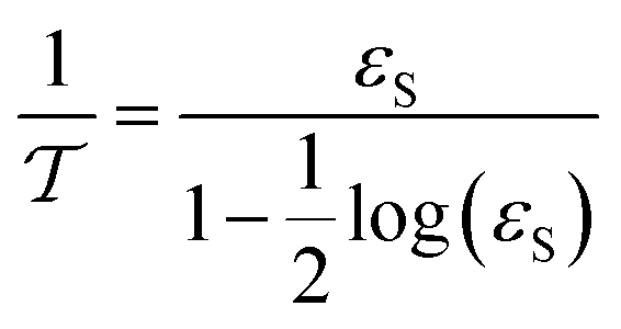


 : heat of reaction at standard temperature (298 K), J mol−1 K−1.
 ,
,  : The heat of formation for products and reactants, respectively, kJ mol−1 K−1.The standards heat of formation for each component are listed in Table S4:†54