DOI:
10.1039/D0RA04669H
(Paper)
RSC Adv., 2020,
10, 33928-33936
Research on the mechanism and reaction conditions of electrochemical preparation of persulfate in a split-cell reactor using BDD anode†
Received
27th May 2020
, Accepted 25th August 2020
First published on 14th September 2020
Abstract
Through a cyclic voltammetry (CV) curve, electron spin resonance spectroscopy (ESR) characterization and a free radical competitive trapping experiment, an analysis was performed on the mechanism of persulfate (PDS) electro-synthesis by sulfate at a boron-doped diamond (BDD) anode. It had been found that there were two pathways of PDS formation. The first was to form PDS through the interaction of sulfate radicals, which were generated from the oxidation reaction mediated by hydroxyl radicals, where the protonized bisulfate ions and sulfuric acid were oxidized by hydroxyl radicals to sulfate radicals. The second was to produce PDS by generating sulfate radicals through the direct loss of electrons from sulfate and bisulfate ions on the electrode surface. In addition, the effects of initial pH, temperature, current density and electrolyte concentration on the synthesis of PDS were investigated in the slotted anode cycle electrolysis mode. As indicated by the results, despite the small effect of the initial pH on PDS synthesis, acidic pH was slightly beneficial to the synthesis of PDS; in electrolysis, the temperature should be controlled below the thermal decomposition temperature of PDS; and in practical application, the increase of impressed current or voltage contributed little to the increase of PDS synthesis concentration and current efficiency. In the case of the impressed current exceeding the limiting current, the adoption of concentrated electrolyte solution shall improve the PDS output and current efficiency.
Introduction
Also referred to as persulfate, peroxodisulfates (S2O82−, PDS) are the most powerful oxidants known in peroxides with a standard redox potential (E0) of 2.01 V. In addition to its application as an oxidant and bleaching agent in the textile, electronics and chemical industries, it is as extensively adopted as one of the oxidants in in situ remediation of soil and water.1,2 On an industrial scale, PDS is usually prepared by electrolyzing low-temperature concentrated sulfuric acid/sulfate solution (>2 mol L−1) at a high current density (≥500 mA cm−2) using a polished Pt electrode or a Ti-based platinum electrode (Ti/Pt) as the anode.1 It is believed by some researchers that, in the electrolysis at a Pt electrode, sulfate is protonized to produce HSO4−, which will directly lose two electrons on the electrode surface with SO42− to synthesize S2O82− (eqn (1) and (2)).3,4 Because the oxygen evolution potential of the Pt electrode is much lower than the electrochemical synthesis potential of S2O82− (eqn (3)), the current efficiency of S2O82− synthesis is low.3 Therefore, oxygen evolution inhibitors, like NH4+, SCN− and ammonium polyphosphate, are added during the electrolysis to increase the output of S2O82−, improve the current efficiency and maintain it within the range of 60–70%. If oxygen evolution inhibitor is not added, the PDS can hardly be prepared on the Pt electrode. And the separation and purification of PDS are challenged because of the corrosion products easily formed on Pt electrode.5| | | 2SO42− → S2O82− + 2e−, E0 = 2.01 V | (1) |
| | | 2HSO4− → S2O82− + 2H+ + 2e−, E0 = 2.123 V | (2) |
| |  | (3) |
With advantages of wide electrochemical potential window, high oxygen-evolution potential and great corrosion resistance, boron-doped diamond (BDD) electrode could produce a large amount of highly oxidizable ˙OH by virtue of its weak adsorption on the surface, thereby has been introduced into the study of electrochemical synthesis of PDS over the years.1,3 Our previous research has performed X-ray diffraction, scanning electron microscope analysis and Raman spectroscopy on the tantalum-based BDD film electrode used here.6 The BDD thin film is about 5 μm thick and is composed of randomly oriented microcrystals. In the Raman spectrum of the BDD electrode, a peak with obvious diamond characteristics (sp3) appears at 1327 cm−1, and the appearance of the peak at 1483 cm−1 can be attributed to the sp2 hybrid structure of graphite-like non-diamond phases. This indicates that the graphite structure formed on the substrate of Ta is structurally complete and has the remarkable features of a high quality polycrystalline diamond thin film.7–9 The crystal structure on the surface of the BDD electrode dramatically increases the contact area between the electrolyte and the electrode surface, which facilitates the adsorption of electrolyte at the active site.10 The boron-doping concentration of the BDD electrode is 2500 ppm; and boron is doped in the interstitial state in substrate materials, so that the conductivity of transition metal Ta is slightly reduced. The diffraction peaks of Ta2C and TaC appear in the X-ray diffraction spectrum of the BDD electrode film.11 But, the diffraction peaks of Ta are significantly stronger, and the main phase of the BDD electrode film is still Ta. This not only gives the electrode excellent conductivity of metal electrodes, but also electrochemical active adsorption sites during the electrolysis, and the electrode is not easy to corrode.12
The mechanism of the generation of S2O82− at BDD anodes has been extensively studied and two probable mechanisms have been proposed. In the process of sulfate solution electrolysis, the oxidation reaction that generates SO4˙− by direct electron transfer should occur before water oxidation; next, as an important intermediate in the synthesis of PDS, SO4˙− can also be generated through the ˙OH mediated oxidation reaction from water oxidation.2,5,13 However, in the mechanisms proposed, no direct experimental evidence has adequately explained the pathway by which SO4˙− is generated.
Sulfate exists extensively in brackish water, mine wastewater and industrial wastewater with a concentration of around thousands of mg L−1 to tens of thousands of mg L−1.14 Generally, brackish water is neutral or slightly alkaline.15 Wastewater containing sulphate, such as the mine wastewater, the effluent of the monosodium glutamate factory, and the wastewater in pharmaceutical industry and food and amino acid industry, is mostly acidic,16,17 while the dyeing wastewater, tannery wastewater and other wastewater, is mostly alkaline.18,19 Since the organic content in brackish water and mine wastewater is low, such wastewater can be used as flexible water resources after desalination. As industrial sulphate-containing wastewater contains various heavy metal ions or complex organic compounds and forms highly toxic substances with sulphates, such industrial wastewater must be treated before discharge or reuse. The in situ electrochemical synthesis of PDS with low-concentration sulfate in such type of water has the following advantages: (1) the addition of the high-concentration sulphate raw materials during industrial preparation of PDS is reduced; and the recycling of sulphate is realized; (2) the organic matter in the water is oxidized and degraded during electrolysis, which to a certain extent purifies the water and also reduces the difficulty of PDS separation and purification; and (3) sulfate-containing wastewater pollution due to the additional addition of persulfate is alleviated. Therefore, the study of the reaction generating PDS under mild conditions (low concentration of sulfate electrolyte, pH 3–9) is of great significance.
The objectives of this study are as follows: firstly, to clearly analyze and explain the mechanism of the generation of persulfate by electrolysis of sulfate on BDD anode through experimental methods, especially the main pathways of persulfate synthesis under the condition of low sulfate concentration; secondly, to evaluate the economy and feasibility of preparing persulfate with sulfate-containing wastewater by analyzing the causes of affecting persulfate formation under different reaction conditions. Therefore, in this study, methods including cyclic voltammetry (CV) scanning, electron paramagnetic resonance spectroscopy (ESR) and free radical competitive capture were used to try to analyze the mechanism of electrochemical synthesis of PDS on the BDD anode. The BDD electrode was used as an anode to form a split circulating electrolytic cell, in which the PDS was synthesized by electrolyzing sulfate solution. The effects of pH, temperature, current densities and sulfate concentrations on PDS generation were studied by single-factor experiment, in order to provide a theoretical basis for the recycling of sulfate in wastewater.
Materials and methods
Materials
The main reagents involved in the experiment include sodium sulfate, potassium iodide, sodium hydroxide, sulfuric acid, tert-butyl alcohol (TBA), carbamazepine (CBZ), sodium persulfate (PDS), sodium bicarbonate, 5,5-dimethyl-1-pyrroline-N-oxide (DMPO), which were all analytically pure; as well as methanol (MeOH) and acetonitrile, which were chromatographically pure. All reagents were directly employed without further purification. All the solutions were prepared with ultrapure water (resistivity 18.2 MΩ cm at 20 °C).
Experimental apparatus
The electrochemical experimental apparatus was composed of three parts, which is shown in Fig. 1. The first part was a custom H-type anode–cathode tank reactor. With an effective volume of 100 mL, its anode and cathode chambers were separated by a cation exchange membrane (Nafion-115, U.S. DuPont) and both were equipped with electrolyte input and output channels. Being BDD (Based on Ta) electrode (25 mm × 50 mm × 1 mm) and Pt electrode (25 mm × 50 mm × 1 mm) respectively, the anode and cathode plates were placed vertically and parallel, with immersion height of 40 mm and spacing of 27 mm.
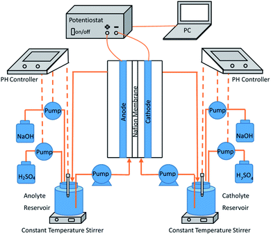 |
| | Fig. 1 Experimental setup for electrochemical preparation of persulfate. | |
The second part was the electrolyte cycling device. The anode electrolyte circulated between the anode chamber and the 250 mL anode electrolyte storage tank at a constant flow rate of 30 mL min−1 through a constant current pump. The liquid storage tank was placed on a constant temperature magnetic agitator to ensure constant temperature (25 ± 2 °C) and uniform concentration of the electrolyte. The cathode circulation was completely symmetrically arranged with that of the anode circulation.
The third part was the dc stabilized power supply, which was connected to the electrode plate through electrode fixtures and provides constant current during the experiment.
CV curve scanning
The CV curve was scanned by electrochemical workstation (CHI600E, Shanghai Chenhua). As a classical conventional three-electrode system, the working electrode of the CV curve test system was BDD electrode, the opposite electrode was Pt electrode, and the reference electrode was saturated calomel electrode (SCE). The experiment was carried out at room temperature of 20 °C with the circulation device closed. High purity nitrogen was introduced for 20 min to remove the dissolved oxygen before scanning. The scanning range was from −2.2 V to 2 V, and the scanning rate was 100 mV s−1.
ESR spectrum characterization
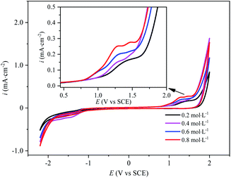
To identify whether there was SO4˙− generated in the process of electro-synthesis of PDS, the ESR spectrum (EMXPLUS 10/12, Bruckner, Germany) analysis was conducted by taking DMPO as the trapping agent. In the experiment, after electrolysis for 15 minutes at the concentration of Na2SO4 electrolyte of 0.1 mol L−1 and the current density of 30 mA cm−2, a syringe filled with DMPO at the concentration of 0.2 mol L−1 in advance was adopted to extract the reaction solution and mix quickly. The generation of ˙OH and SO4˙− was explored on account of the signal peaks of DMPO-˙OH and DMPO-SO4˙−. The condition of ESR detection was microwave power of 20 mW, modulation frequency of 100 kHz, central field of 3510.00 G, scanning width of 100.0 G, scanning time of 60 s, and gain of 30 dB.
Free radical competitive trapping
CBZ was taken as free radical probe, while methanol and tert-butyl alcohol were taken as free radical scavenger, respectively. The degree of oxidative degradation of CBZ in BDD anode electrolysis was measured at the initial concentration of CBZ of 10 μmol L−1, the current density of 30 mA cm−2 and the electrolyte concentration of Na2SO4 of 0.1 mol L−1. In the blank control experiment of CBZ direct electrolysis, NaClO4 was introduced to prepare the background electrolyte solution, in view of its favorable stability and oxidation resistance in anode electrolysis.20 The concentration of CBZ was determined by high performance liquid chromatography (Agilent 1260 Infinity II) with a UV detector, a C18 column, a acetonitrile (60%)/water (40%) flow matching ratio and a detection wavelength of 286 nm. 0.22 μm organic filtration membrane was required before injection. The same experiment repeated at least twice.
Effect of reaction conditions on the electro-preparation of PDS
In the experiment, the initial pH before electrolysis was adjusted to 3, 5, 7 and 9 through NaOH (1 mol L−1) and H2SO4 (1 mol L−1), respectively. At the current density of 30 mA cm−2 and Na2SO4 concentration of 0.1 mol L−1, the effect of initial pH on PDS generation was researched. At the current density of 30 mA cm−2 and Na2SO4 concentration of 0.1 mol L−1, the generation of PDS at 15 °C, 25 °C and 40 °C was respectively investigated without adjusting the initial pH. In addition, an 1 h electrolysis was carried out at the Na2SO4 electrolyte concentration of 0.2–0.8 mol L−1 and current density of 30–120 mA cm−2 without adjusting the initial pH, so as to identify the effect of current density and electrolyte concentration on PDS generation respectively. The same experiment repeated at least twice.
PDS was determined by UV-vis spectrophotometry (UV-5200, Shanghai Yuanxi) based on the improved iodimetry.21 PDS has strong oxidizing properties. The PDS anion reacts with KI in the presence of sodium bicarbonate and forms I3− (eqn (4) and (5)), which iodine yellow color that absorbs in the UV-vis range with maximum absorptions at 352 nm. Sodium bicarbonate must be added to the potassium iodide solution to prevent iodide from contacting with air and oxidizing.
| | | S2O82− + 2I− → 2SO42− + I2 | (4) |
The ratio of the amount of charge effectively utilized by PDS generation was reflected by Faraday current efficiency, which is calculated as follows (eqn (6)):
| |  | (6) |
where,
n is the number of electrons transferred by the reaction, 2;
C is the molality of S
2O
82−, mol L
−1;
V is the volume of electrolyte, L;
F is the Faraday constant, 96
![[thin space (1/6-em)]](https://www.rsc.org/images/entities/char_2009.gif)
485 C mol
−1;
I is the current, A;
t is the electrolysis time, s.
Results and discussion
CV curve of BDD anode in sulfate
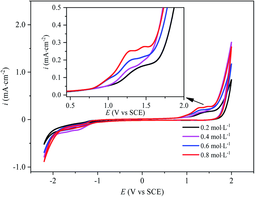
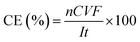
The electrochemical behavior of sulfate on the surface of BDD electrode is the key to the analysis of PDS synthesis mechanism. The CV curves of BDD electrode with different concentrations of Na2SO4 electrolyte are as shown in Fig. 2. This could be found that the oxidation peak corresponding to the direct oxidation of SO42− occurred between 1.2 V and 1.5 V. With the increase of Na2SO4 concentration, the resistance of the electrolyte solution decreases, the oxidation peak moved to the direction of negative potential and the peak current increased. The oxidation peak current of the BDD electrode in the Na2SO4 electrolyte at a concentration of 0.8 mol L−1 was almost twice as much as that in the Na2SO4 electrolyte at a concentration of 0.2 mol L−1, suggesting that the increase of the concentration of the BDD electrode promoted its electron exchange rate at BDD electrode and thus facilitated its direct oxidation. As the concentration of SO42− increased, the peak width of the oxidation peak increased and the smoothness of the peak shape decreased, which might be attributed to the generation of other oxidizing substances (such as H2O2 and O2˙−) in the electrolysis process,22 in spite of the minimal output of these substances.
 |
| | Fig. 2 Cyclic voltammetry curves of BDD electrodes in Na2SO4 electrolytes with different concentrations. | |
In Fig. 2, at the voltage of 2 V, the current density for the solution concentrated at 0.4 mol L−1 is even higher than those at 0.6 mol L−1 and 0.8 mol L−1. The electrode reaction changed with the increase of the concentration of sulfate electrolyte. When the sulfate concentration was 0.4 mol L−1, the active species on the electrode surface might be different. In the meantime, affected by mass transfer, the thickness of the diffuse double layer got relatively smaller, so the current was relatively high.
In Fig. 2, the oxygen evolution potential and the hydrogen evolution potential are 1.8 V and −1.2 V, respectively. The forward scan curve and the reverse scan curve cannot coincide. The electrode reaction was less reversible. In the sulfate electrolyte, the electrochemical reaction on the BDD electrode involved several redox pairs. The most classical irreversible chemical reaction system was the electrolysis of water (eqn (3) and (7)).1,23–25 Then, SO42− was not inert during anodic electrolysis and could lose an electron on the surface of the BDD electrode to generate SO4˙−. SO4˙− could not exist stably in electrolyte solution and could only exist near the surface of the electrode to continue to join the oxidation reaction to form other oxidation products, or it would be quenched very quickly. Therefore, the reaction became chemically irreversible. Although the oxidation product S2O82− could exist stably in the electrolyte solution for some time, it generated SO42− and SO4˙− mainly by obtaining an electron (eqn (8)), while S2O82− had several reaction paths in the anodic oxidation process. Therefore, during CV curve scanning, when the direction of the current changed, different redox reactions occurred on the electrode, forming a chemically irreversible system, thus resulting in the asymmetry of the CV curve.
| | | 2H2O + 2e− → H2 + 2OH− | (7) |
| | | S2O82− + e− → SO42− + SO4˙− | (8) |
ESR spectrum characterization of sulfate radical SO4˙−
To identify whether there was SO4˙− generated in the process of electro-synthesis of PDS, the ESR spectrum analysis was conducted by taking DMPO as the trapping agent, with results obtained in Fig. 3. Through the introduction of ESR signal acquisition software, simulation analysis was conducted according to the hyperfine coupling constant of DMPO-˙OH and DMPO-SO4˙− (DMPO-˙OH: αN = 14.9 G, αH = 14.9 G (g-factor of 2.009); DMPO-SO4˙−: αN = 13.2 G, αH = 9.6 G, αH = 1.48 G and αH = 0.78 G).26–28 The results showed the typical quartet lines of DMPO-˙OH admixture (with a peak intensity ratio of 1:2:2:1) and the typical sextet lines of DMPO-SO4˙− (with a peak intensity ratio of 1:1:1:1:1:1), indicating that both ˙OH and SO4˙− were produced in the process of electro-preparation of PDS by sulfate at BDD anode. According to the estimation based on the absolute height of peak intensity, the output of ˙OH in the transient state was much larger than that of SO4˙−.
 |
| | Fig. 3 ESR spectrum of Na2SO4 electrolysis at BDD anode. | |
Free radical competitive trapping and analysis of PDS synthesis mechanism
To further analyze the generation pathway of SO4˙− on the surface of BDD anode, MeOH and TBA were taken as free radical scavengers to conduct competitive trapping of SO4˙−. In view of the close reaction rate constant between MeOH and SO4˙− and ˙OH (only about 1 order of magnitude difference), the addition of excessive MeOH shall remove both SO4˙− and ˙OH at the same time. In contrast, since the reaction rate constant with ˙OH is about three orders of magnitude higher than that with SO4˙−, TBA without α-hydrogen is mainly adopted for the removal of ˙OH. In order to ensure the effective scavenging of free radicals by quenchants, the concentrations of MeOH and TBA were set at a higher level of mol L−1 in the competitive trapping experiment. The main reactions and rate constants in the experiment are as shown in Table 1.
Table 1 Quenching reaction and rate constant in competitive trapping experiment
| No. |
Reaction formula |
Rate constant, k (L mol−1 s−1) |
Reference |
| 1 |
MeOH + ˙OH → product |
9.7 × 10⁸ |
29 and 30
|
| 2 |
MeOH + SO4˙− → product |
1.1 × 10⁷ |
30 and 31
|
| 3 |
TBA + ˙OH → product |
6 × 10⁸ |
29 and 30
|
| 4 |
TBA + SO4˙− → product |
8.4 × 10⁵ |
30 and 31
|
| 5 |
CBZ + ˙OH → product |
8.8 × 10⁹ |
32
|
| 6 |
CBZ + SO4˙− → product |
∼109 |
32
|
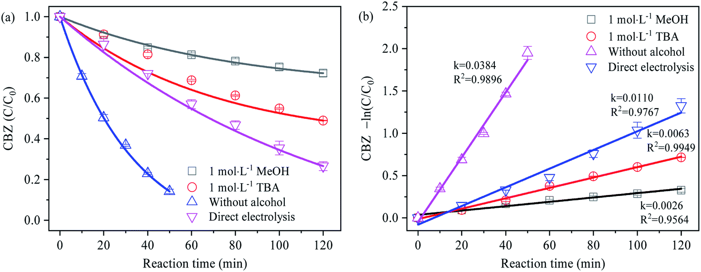
Given the negligible contribution of PDS alone to the degradation of CBZ,32 CBZ was selected as the free radical probe in the experiment. Based on the different degradation degree of CBZ caused by the competitive trapping of SO4˙− by MeOH and TBA, the generation of SO4˙− was analyzed to obtain the results as shown in Fig. 4. The degradation of CBZ under different electrolysis conditions was in accordance with the first-order kinetics. The relative contribution ratio of different oxidizing species to CBZ degradation was calculated according to the ratio of reaction rate, as shown in Table 2 below:
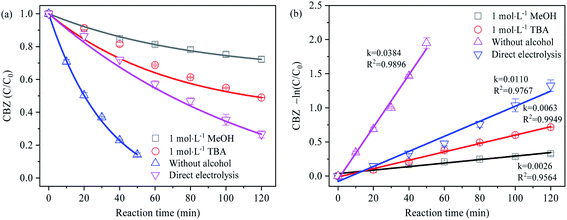 |
| | Fig. 4 (a) Effect of methanol and tert-butanol on the degradation of CBZ; (b) first-order reaction rate of CBZ degradation. | |
Table 2 Contribution rate of oxide species to CBZ degradation (relatively)
| Reaction conditions |
Oxidizing species |
First-order reaction rate (min−1) |
Contribution ratio |
| Without alcohol |
DET + SO4˙− + ˙OH |
0.0384 |
100% |
| Direct electrolysis |
DET + ˙OH |
0.0110 |
28.65% |
| 1 mol L−1 MeOH |
DET |
0.0026 |
6.77% |
| ˙OH |
0.0084 |
16.15% |
| SO4˙− |
0.0274 |
71.35% |
In the process of direct electrolysis, the degradation rate of CBZ mainly depended on the direct electron transfer (DET) on the electrode surface and the oxidation reaction mediated by ˙OH, at a first-order reaction rate of 0.0110 min−1. In the Na2SO4 electrolyte, CBZ was rapidly degraded in a very short time (0.0384 min−1) without considering the oxidation of PDS, indicating that the electrolysis at BDD anode could activate SO42− into highly oxidizable SO4˙−, which was in coordination with ˙OH to facilitate the degradation of organics. The relative contribution ratio of SO4˙− to CBZ degradation in this reaction reached 71.35%. In addition, the electrolysis process might as well produce oxidizing active substances such as O2˙−, HO2˙ and 1O2.22,33–35 According to the detection of ESR signal peaks above, however, no other obvious characteristic peaks were observed except for SO4˙− and ˙OH, implying the negligible impact of oxidizing active substances such as O2˙−, HO2˙ and 1O2 on the relative contribution rate of SO4˙− study.
In the free radical scavenging experiment, the first-order reaction rates of CBZ after adding TBA and MeOH were 0.0063 min−1 and 0.0026 min−1, respectively. Since the degradation of CBZ was significantly inhibited, it was inferred that the generation of SO4˙− might be mainly the result of ˙OH induction. In the case that the indirect induction of ˙OH was the only way to generate SO4˙−, and the removal rate of ˙OH by TBA and MeOH was similar (the order of magnitude of 109 mol−1 s−1), the first-order reaction rate of CBZ degradation in sodium sulfate electrolyte containing excessive TBA and MeOH respectively should be basically the same. However, the contrary results showed that SO4˙− can be produced by direct electron transfer oxidation.
Analysis of preparation mechanism
According to the CV curve, ESR spectrum and the results of free radical competitive trapping experiment, there were two possible paths for the electro-synthesis of PDS by sulfate at BDD anode. On the one hand, due to the weak interaction between the BDD film and the electrochemical reactive oxygen species, a large number of ˙OH-mediated oxidation reactions could take place on the electrode surface. After H2O lost electrons on the surface of the BDD electrode and generated ˙OH (eqn (9)), the protonized HSO4− and H2SO4 could be oxidized by ˙OH to SO4˙− (eqn (10) and (11)), which generated S2O82− through interaction (eqn (12)).3,36 This was consistent with Serrano et al.'s hypothesis of PDS generation mechanism on BDD electrode based on the analysis of CV curve.3 Some researchers argued that apart from being induced by ˙OH, direct electron transfer might as well result in PDS generation. By introducing density functional theory (DFT) and molecular dynamics (MD) models, Davis and Farrell et al. investigated possible reaction pathways for the preparation of PDS at BDD electrodes, and it was deduced that the direct loss of electrons from SO42− and HSO4− on the electrode surface would produce SO4˙− (eqon (13)–(16)) and further generated S2O82−,2,5 as verified by the ESR spectrum and free radical competitive trapping experiment above.| | | H2O → ˙OH + H+ + e−, E0 = 2.72 V vs. SHE | (9) |
| | | HSO4− + ˙OH → SO4˙− + H2O | (10) |
| | | H2SO4 + ˙OH → SO4˙− + H3O+ | (11) |
| | | SO4˙− + SO4˙− → S2O82− | (12) |
| | | SO42− → SO4˙− + e−, E0 = 3.4 V vs. SHE | (13) |
| | | HSO4− → SO4˙− + H+ + e− | (14) |
| | | SO4˙− + SO42− → S2O82− + e−, E0 = 0.6 V vs. SHE | (15) |
| | | SO4˙− + HSO4− → S2O82− + H+ + e− | (16) |
In the preparation process of the PDS by electrolyzing sulfate on the BDD anode, the oxygen evolution reaction was the main side reaction reducing the current efficiency. The evolution mechanism of O2 on the BDD electrode included two steps: first, due to the sp3 hybrid structure on the surface of the BDD electrode, the adsorption capacity of the reaction intermediate was weak on its surface, while H2O lost an electron on the electrode surface and formed ˙OH (eqn (9)). Second, the redox potential of ˙OH is 1.8–2.7 V, and it is strongly oxidizing. In addition to indirectly oxidizing sulfates to produce the PDS, the competing reactions among ˙OH combined to produce O2 (eqn (17)).3 The PDS was unstable in water and would decompose to produce O2 (eqn (18)). Besides, the pH value decreased constantly as the anode electrolysis got on, and Caro's acid might be produced in this process. Its oxidation rate in the electrolyte solution was higher than its formation rate. Thus, the quantities of Caro's acid were low (eqn (19) and (20)).
| | | ˙OH + ˙OH → O2 + 2H+ + 2e− | (17) |
| |  | (18) |
| | | H2S2O8 + H2O → H2SO5 + H2SO4 | (19) |
| | | H2SO5 + H2O → O2 + H2SO4 + 2H+ + 2e− | (20) |
Effect of pH on PDS generation
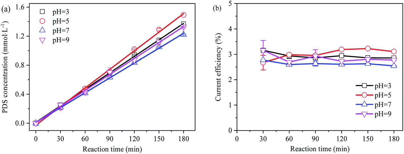
Despite high sulfate concentrations in mine and industrial wastewater, they are mostly acidic. Therefore, the effect of pH should be taken into account when sulfate at high concentrations in such wastewater is utilized for the electro-preparation of PDS. In the separated anode electrolysis experiment, the rate of protons passing through the ion-exchange membrane to the cathode was slower than the oxidation reaction producing protons,37 and the pH value rapidly dropped below 2. The concentration and current efficiency of the electro-synthesis of PDS by sulfate at different initial pH are shown in Fig. 5.
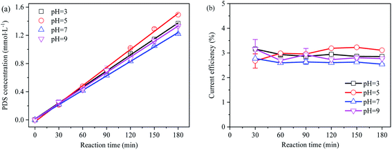 |
| | Fig. 5 (a) Effect of pH on electro-synthetic PDS; (b) effect of pH on current efficiency of synthetic PDS. | |
The generation of PDS followed the zero-order reaction kinetics in the split cycle anode electrolysis mode. Despite the weak effect of initial pH on PDS synthesis, acidic pH conditions were more favorable to the PDS generation than alkaline pH conditions. As an intermediate active substance in PDS generation, under neutral or basic pH conditions, SO4˙− might be reduced to SO42− before generating ˙OH. As the reverse reaction of ˙OH oxidizing SO42− to form SO4˙− (eqn (21) and (22)), it was not conducive to the generation of PDS.38,39 As suggested by previous studies, PDS demonstrated a slow decomposition efficiency in neutral and alkaline aqueous solutions (eqn (23) and (24)).40–42 Since the decomposition of PDS is much slower than its formation, no additional acid–base neutralizer is required to synthesize PDS from acidic sulfate wastewater.
| | | SO4˙− + H2O → SO42− + H+ + ˙OH | (21) |
| | | SO4˙− + OH− → SO42− + ˙OH | (22) |
| |  | (23) |
| | | S2O82− + OH− → HSO4− + SO52− | (24) |
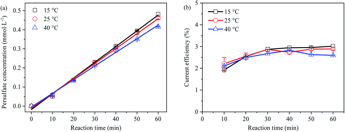
Effect of temperature on PDS generation
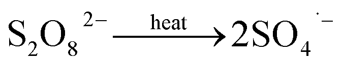
The generation concentration and current efficiency of PDS at different temperatures (15 °C, 25 °C and 40 °C) are shown in Fig. 6, indicating the PDS output and current efficiency decreased with the increase of temperature. The reason lied in that, under the condition of thermal enhancement (≥40 °C), S2O82− might homogenize and decompose into SO4˙− with great oxidation due to thermal activation (eqn (25)), resulting in the decrease of PDS concentration.41,43| | 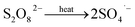 | (25) |
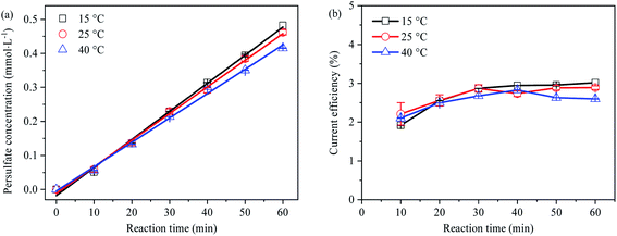 |
| | Fig. 6 (a) Effect of temperature on electro-synthetic PDS; (b) effect of temperature on current efficiency of synthetic PDS. | |
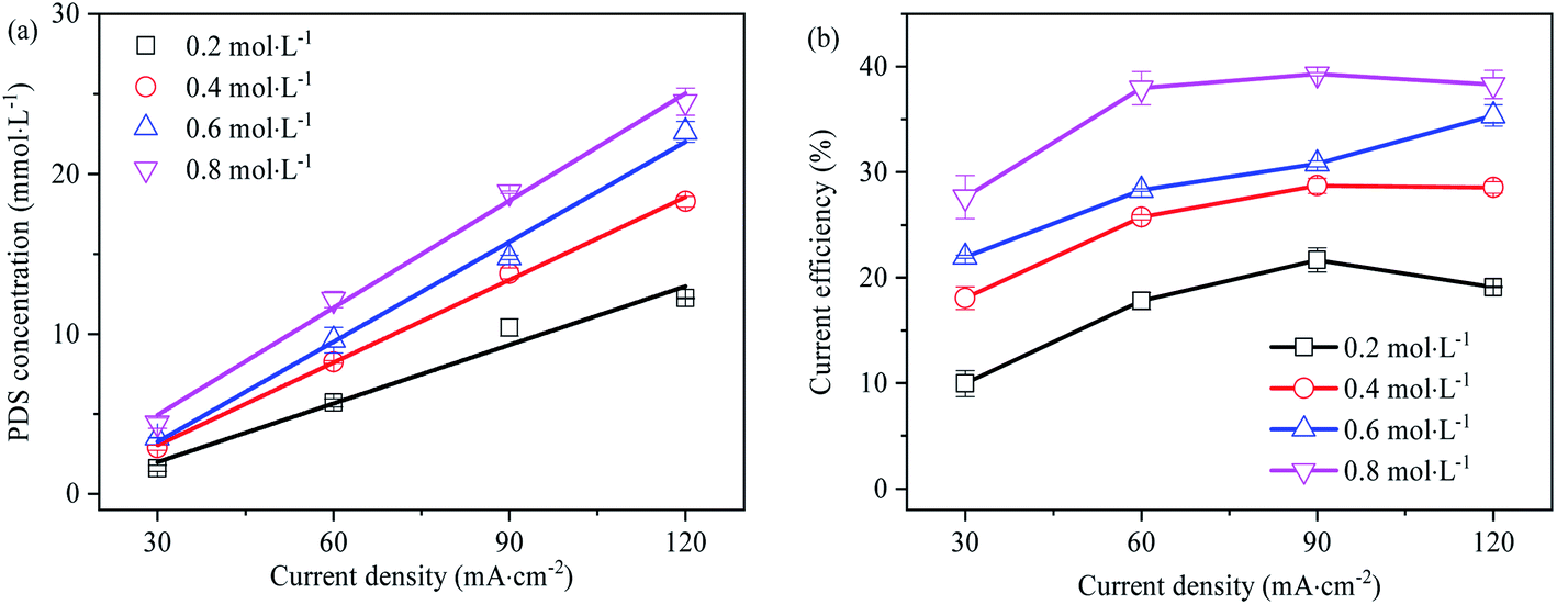
Effect of current density on PDS generation
In Fig. 7, the effect of current density on PDS synthesis is investigated. There is a linear relationship between PDS output and current density, and the linear regression coefficients are all greater than 0.95. The output of PDS rise with the increase of current density. At high current densities from 60 mA cm−2 to 120 mA cm−2, the current efficiency of PDS synthesis is higher and hardly changed with the increase of current density, while at low current density 30 mA cm−2, the current efficiency of PDS synthesis is lower. During the preparation of persulfate with 0.2, 0.4, 0.6 and 0.8 mol L−1 Na2SO4 as the electrolyte solution, the synthesis of persulfate almost increases linearly as the current densities rise (as shown in Fig. S4–S7†). This embodied the critical role of current density in the reaction rate and current efficiency of PDS synthesis. Each current density value was driven by a certain over-potential, and the limiting current corresponded to the limiting potential. In the electrolysis process, the occurrence of different electrode reactions was on the premise that the impressed current exceeds the limiting current. Therefore, the low current density might constitute a limitation to the reaction of direct oxidation synthesis of PDS. Moreover, a large amount of gas was produced in the anode during electrolysis, indicating that the synthesis of PDS was accompanied by the side reaction of oxygen evolution. On the one hand, the oxygen evolution reaction competed with SO42− for the reactive sites on the electrode surface to inhibit its direct oxidation; on the other hand, the effective electrode area of PDS synthesis was reduced due to the partial attachment of O2 generated on the electrode surface.44 The oxygen evolution was more intense at low current density, which led to a significant decrease in current efficiency.
 |
| | Fig. 7 (a) Effect of current density on the synthesis of PDS (electrolysis time is 1 h); (b) effect of current density on current efficiency of synthetic PDS (electrolysis time is 1 h). | |
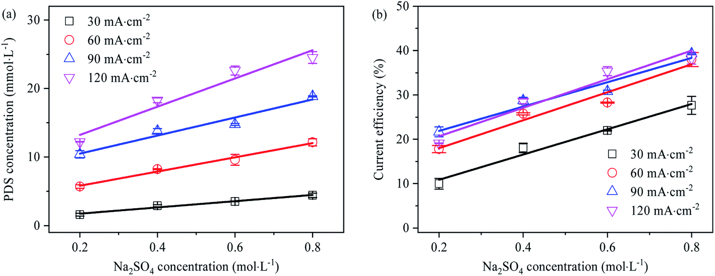
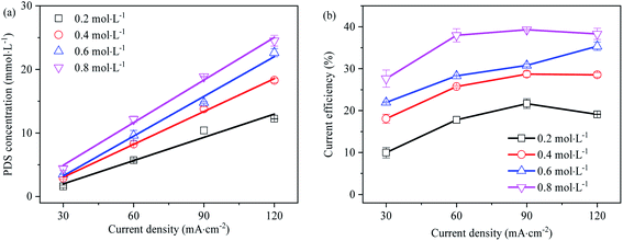
Effect of SO42− concentration on PDS generation
The effect of Na2SO4 electrolyte solution concentration on PDS generation is shown in Fig. 8. With the increase of Na2SO4 concentration, the generation concentration and current efficiency of PDS grew linearly. Firstly, it might be that the increase of SO42− concentration enabled it occupy more reaction-active adsorption sites on the electrode surface, which led to the enhancement of direct electrolysis capability. Secondly, from the perspective of chemical thermodynamics, the increase in SO42− concentration made the electrolytic equilibrium biased in favor of PDS synthesis and led to the increase in PDS generation. Under different current densities, the current efficiency of PDS synthesis grew linearly with the increase of Na2SO4 concentration. However, at the current density of 60–120 mA cm−2, the current efficiency demonstrated a consistent growth with the increase of Na2SO4 electrolyte concentration, while at the current density of 30 mA cm−2, the current efficiency was significantly lower. As indicated by the results, within the concentration range, low current density might make PDS synthesis mainly through ˙OH mediated oxidation; when the current density exceeded the limiting current density, the current efficiency mainly changed with the concentration of the electrolyte solution rather than current density. Also, this implied that in addition to ˙OH mediated oxidation, as an intermediate substance of PDS synthesis, SO42− might generate SO4˙− mainly through rapid electron transfer at higher concentrations.13 According to the above rules, we can roughly infer that the current efficiency of the PDS can be above 78% when the concentration of sulfate electrolyte is 2 mol L−1 and the current density is 120 mA cm−2. Thanks to the low current density, this process was energy-saving. In addition, this method did not need the addition of oxygen evolution inhibitors, which helped prepare PDS products with low impurity content and lower the cost of separation and purification.
 |
| | Fig. 8 (a) Effect of Na2SO4 electrolyte concentration on electro-synthesis of PDS (electrolysis time is 1 h); (b) effect of Na2SO4 electrolyte concentration on current efficiency of synthetic PDS (electrolysis time is 1 h). | |
Although this method required no oxygen evolution inhibitor, the output and current efficiency of the PDS could also be maintained at a high level. Furthermore, the ˙OH, SO4˙−, S2O82− and other substances that were strongly oxidizing from the electrolysis ensured more thorough decomposition of organic impurities. This was conducive to the preparation of PDS products with less impurities.26,45 At present, the separation and purification methods for salts mainly include ion exchange, electrodialysis, crystallization and precipitation. The separation and purification of PDS from electrolyte solution require further study.
Conclusions
The electrochemical synthesis mechanism of PDS at BDD anode was interpreted through experimental methods of CV curve, electron spin resonance spectroscopy (ESR) and free radical competitive trapping; in the split anode electrolysis mode, the effects of reaction conditions including pH, temperature, current density and electrolyte concentration of the electro-synthesis of PDS by sulfate at BDD anode was identified. According to the results: (1) based on the formation of intermediate substance SO4˙− of PDS synthesis, it was concluded that there were two possible paths for PDS synthesis by sulfate at BDD anode. The first was that SO42− was induced by indirect oxidation of ˙OH to form SO4˙−; the second was that when the impressed current density exceeded the limiting current density, the electron loss rate of SO42− on the surface of BDD electrode increased, resulting the growth of SO4˙− generated by direct oxidation. (2) In a split-cell reactor, the initial pH contributed little on PDS synthesis, and the acidic condition was slightly beneficial to PDS synthesis. No additional pH regulator is required for the synthesis of PDS with sulfate from acid mine and industrial wastewater. (3) At a temperature higher than 40 °C, thermal decomposition of PDS resulted in the decrease of its output and current efficiency. It is suggested the necessity of ensuring the temperature lower than its thermal decomposition temperature in the electro-synthesis of PDS; (4) in practical application, the increase of impressed current or voltage assumes no significant contribution to the improvement of current efficiency of PDS synthesis. In case of the impressed current exceeding the limiting current, the PDS cumulative concentration and current efficiency can be improved through concentrated pretreatment of sulfate solution.
Conflicts of interest
There are no conflicts to declare.
Acknowledgements
The research was supported by Youth Program of National Natural Science Foundation of China (Grant No. 51408397) and Natural Science Foundation of Shanxi Province (Grant No. 201801D121275).
References
- J. Zhu, K. K. Hii and K. Hellgardt, ACS Sustainable Chem. Eng., 2016, 4, 2027–2036 CrossRef CAS.
- J. Davis, J. C. Baygents and J. Farrell, Electrochim. Acta, 2014, 150, 68–74 CrossRef CAS.
- K. Serrano, P. A. Michaud, C. Comninellis and A. Savall, Electrochim. Acta, 2002, 48, 431–436 CrossRef CAS.
- G. B. Balazs, J. F. Cooper and T. E. Shell, J. Appl. Electrochem., 1999, 29, 285–292 CrossRef CAS.
- D. Khamis, E. Mahé, F. Dardoize and D. Devilliers, J. Appl. Electrochem., 2010, 40, 1829–1838 CrossRef CAS.
- J. Zhai, F. Zhang, Z. Sun, H. Li, C. Wang and J. Cui, Appl. Chem. Ind., 2020, 49, 555–560 Search PubMed.
- E. Mahé, D. Devilliers and C. Comninellis, Electrochim. Acta, 2005, 50, 2263–2277 CrossRef.
- J. Lee, Y. Li, J. Tang and X. Cui, Acta Phys.-Chim. Sin., 2018, 34, 1080–1087 CAS.
- X.-Y. Yue, A. Abulikemu, X.-L. Li, Q.-Q. Qiu, F. Wang, X.-J. Wu and Y.-N. Zhou, J. Power Sources, 2019, 410, 132–136 CrossRef.
- J. Xu, E. Gu, Z. Zhang, Z. Xu, Y. Xu, Y. Du, X. Zhu and X. Zhou, J. Colloid Interface Sci., 2020, 567, 84–91 CrossRef CAS.
- X. Li, H. Li, M. Li, C. Li, D. Sun, Y. Lei and B. Yang, Carbon, 2018, 129, 543–551 CrossRef CAS.
- X. Ge, S. Liu, M. Qiao, Y. Du, Y. Li, J. Bao and X. Zhou, Angew. Chem., Int. Ed., 2019, 58, 14578–14583 CrossRef CAS.
- K. C. de Freitas Araújo, D. R. da Silva, E. V. dos Santos, H. Varela and C. A. Martínez-Huitle, J. Electroanal. Chem., 2020, 860, 113927 CrossRef.
- Y. Choi, G. Naidu, S. Jeong, S. Lee and S. Vigneswaran, Desalination, 2018, 426, 78–87 CrossRef CAS.
- H. Zhang, L. Wu, W. Gu, Y. Xu and J. Tao, Environ. Earth Sci., 2016, 75, 667 CrossRef.
- S. Papirio, D. K. Villa-Gomez, G. Esposito, F. Pirozzi and P. N. L. Lens, Crit. Rev. Environ. Sci. Technol., 2013, 43, 2545–2580 CrossRef CAS.
-
S. Huang and T.-S. Chow Alex, Influence of Iron Salt on the Treatment of Monosodium-Glutamate Wastewater by Biochemistry Process, 2008 Search PubMed.
- H. Wu and S. Wang, J. Hazard. Mater., 2012, 243, 86–94 CrossRef CAS.
- M.-V. Galiana-Aleixandre, J.-A. Mendoza-Roca and A. Bes-Piá, J. Cleaner Prod., 2011, 19, 91–98 CrossRef CAS.
- A. G. Davidian, A. G. Kudrev, L. A. Myund and M. K. Khripun, J. Near Infrared Spectrosc., 2014, 22, 121–128 CrossRef CAS.
- C. Liang, C.-F. Huang, N. Mohanty and R. M. Kurakalva, Chemosphere, 2008, 73, 1540–1543 CrossRef CAS.
- J. Zhao, W. Guo, J. Li, H. Chu and Y. Tu, Electrochim. Acta, 2012, 61, 118–123 CrossRef CAS.
- L. W. Matzek, M. J. Tipton, A. T. Farmer, A. D. Steen and K. E. Carter, Environ. Sci. Technol., 2018, 52, 5875–5883 CrossRef CAS PubMed.
- J. E. Silveira, A. L. Garcia-Costa, T. O. Cardoso, J. A. Zazo and J. A. Casas, Electrochim. Acta, 2017, 258, 927–932 CrossRef CAS.
- W.-S. Chen, Y.-C. Jhou and C.-P. Huang, Chem. Eng. J., 2014, 252, 166–172 CrossRef CAS.
- L. C. Chen, C. J. Lei, Z. J. Li, B. Yang, X. W. Zhang and L. C. Lei, Chemosphere, 2018, 210, 516–523 CrossRef CAS PubMed.
- K. Wang, D. Huang, W. Wang, Y. Ji and J. Niu, Environ. Int., 2020, 137, 105562 CrossRef CAS.
- G. Fang, C. Liu, J. Gao, D. D. Dionysiou and D. Zhou, Environ. Sci. Technol., 2015, 49, 5645–5653 CrossRef CAS.
- G. V. Buxton, C. L. Greenstock, W. P. Helman and A. B. Ross, J. Phys. Chem. Ref. Data, 1988, 17, 513–886 CrossRef CAS.
- P. Xie, J. Ma, W. Liu, J. Zou, S. Yue, X. Li, M. R. Wiesner and J. Fang, Water Res., 2015, 69, 223–233 CrossRef CAS.
- C. L. Clifton and R. E. Huie, Int. J. Chem. Kinet., 1989, 21, 677–687 CrossRef CAS.
- H. Song, L. Yan, J. Jiang, J. Ma, Z. Zhang, J. Zhang, P. Liu and T. Yang, Water Res., 2018, 128, 393–401 CrossRef CAS PubMed.
- M. M. Ahmed and S. Chiron, Water Res., 2014, 48, 229–236 CrossRef CAS PubMed.
- Z. Duan, L. Deng, Z. Shi, H. Zhang, H. Zeng and J. Crittenden, J. Colloid Interface Sci., 2019, 534, 270–278 CrossRef CAS.
- J. Hollman, J. A. Dominic and G. Achari, Chemosphere, 2020, 248, 125911 CrossRef CAS PubMed.
- Y.-U. Shin, H.-Y. Yoo, Y.-Y. Ahn, M. S. Kim, K. Lee, S. Yu, C. Lee, K. Cho, H.-i. Kim and J. Lee, Appl. Catal., B, 2019, 254, 156–165 CrossRef CAS.
- A. Schranck and K. Doudrick, Water Res., 2020, 168, 115130 CrossRef CAS PubMed.
- Y.-H. Guan, J. Ma, X.-C. Li, J.-Y. Fang and L.-W. Chen, Environ. Sci. Technol., 2011, 45, 9308–9314 CrossRef CAS PubMed.
- Y. Ji, C. Dong, D. Kong, J. Lu and Q. Zhou, Chem. Eng. J., 2015, 263, 45–54 CrossRef CAS.
- C. Liang, Z.-S. Wang and C. J. Bruell, Chemosphere, 2007, 66, 106–113 CrossRef CAS PubMed.
- S. G. Huling, S. Ko, S. Park and E. Kan, J. Hazard. Mater., 2011, 192, 1484–1490 CrossRef CAS.
- Z.-H. Huang, Z.-Y. Ji, Y.-Y. Zhao, J. Liu, F. Li and J.-S. Yuan, Chem. Eng. J., 2020, 380, 122411 CrossRef CAS.
- R. L. Johnson, P. G. Tratnyek and R. O. B. Johnson, Environ. Sci. Technol., 2008, 42, 9350–9356 CrossRef CAS.
- J. R. Davis, J. C. Baygents and J. Farrell, J. Appl. Electrochem., 2014, 44, 841–848 CrossRef CAS.
- A. Farhat, J. Keller, S. Tait and J. Radjenovic, Environ. Sci. Technol., 2015, 49, 14326–14333 CrossRef CAS.
Footnote |
| † Electronic supplementary information (ESI) available. See DOI: 10.1039/d0ra04669h |
|
| This journal is © The Royal Society of Chemistry 2020 |
Click here to see how this site uses Cookies. View our privacy policy here. 
 Open Access Article
 This Open Access Article is licensed under a Creative Commons Attribution-Non Commercial 3.0 Unported Licence
 *,
Zhiyu
Sun
and
Jianguo
Cui
*,
Zhiyu
Sun
and
Jianguo
Cui