
 Open Access Article
 This Open Access Article is licensed under a Creative Commons Attribution-Non Commercial 3.0 Unported Licence
Solid-state synthesis of few-layer cobalt-doped MoS2 with CoMoS phase on nitrogen-doped graphene driven by microwave irradiation for hydrogen electrocatalysis†
Junpeng
Fan
 a,
Joakim
Ekspong
a,
Anumol
Ashok
b,
Sergey
Koroidov
c and
Eduardo
Gracia-Espino
*a
a,
Joakim
Ekspong
a,
Anumol
Ashok
b,
Sergey
Koroidov
c and
Eduardo
Gracia-Espino
*a
aDepartment of Physics, Umeå University, Umeå 90187, Sweden. E-mail: eduardo.gracia@umu.se
bDepartment of Materials and Environmental Chemistry, Stockholm University, Stockholm 106 91, Sweden
cDepartment of Physics, Stockholm University, Stockholm 106 91, Sweden
First published on 16th September 2020
Abstract
The high catalytic activity of cobalt-doped MoS2 (Co–MoS2) observed in several chemical reactions such as hydrogen evolution and hydrodesulfurization, among others, is mainly attributed to the formation of the CoMoS phase, in which Co occupies the edge-sites of MoS2. Unfortunately, its production represents a challenge due to limited cobalt incorporation and considerable segregation into sulfides and sulfates. We, therefore, developed a fast and efficient solid-state microwave irradiation synthesis process suitable for producing thin Co–MoS2 flakes (∼3–8 layers) attached on nitrogen-doped reduced graphene oxide. The CoMoS phase is predominant in samples with up to 15 at% of cobalt, and only a slight segregation into cobalt sulfides/sulfates is noticed at larger Co content. The Co–MoS2 flakes exhibit a large number of defects resulting in wavy sheets with significant variations in interlayer distance. The catalytic performance was investigated by evaluating the activity towards the hydrogen evolution reaction (HER), and a gradual improvement with increased amount of Co was observed, reaching a maximum at 15 at% with an overpotential of 197 mV at −10 mA cm−2, and a Tafel slope of 61 mV dec−1. The Co doping had little effect on the HER mechanism, but a reduced onset potential and charge transfer resistance contributed to the improved activity. Our results demonstrate the feasibility of using a rapid microwave irradiation process to produce highly doped Co–MoS2 with predominant CoMoS phase, excellent HER activity, and operational stability.
Introduction
Molybdenum disulfide, a layered transition metal dichalcogenide, is well recognized as a promising catalyst for several chemical and electrochemical processes, and its success relies on the possibility of tuning its intrinsic properties by phase, defect, and edge engineering.1–3 In particular, the feasibility of incorporating diverse transition metals into the MoS2 lattice has been a successful strategy to easily modify the overall catalytic performance, where in particular Co doping has shown the best performance for several reactions such as hydrogen evolution reaction (HER),4 hydrodesulfurization (HDS),5,6 carbon monoxide reduction,7 and sodium-ion batteries,8 among others. Cobalt incorporation into MoS2 might occur as Co replacing Mo atoms along the MoS2 lattice without a particular order, or as a more peculiar arrangement where Co mainly occupies the edge-sites of MoS2 flakes, in what is known as the CoMoS phase.9,10 This phase is often observed at low cobalt doping, and it has been identified as the active phase/sites for both HER and HDS reactions,4–6 while at large doping concentration there is often cobalt segregation into cobalt sulfides and sulfates, resulting in lower catalytic activity.9,10 Therefore, incorporating Co atoms to form the CoMoS phase is critical for the activity of Co–MoS2 catalysts, and thus several synthetic routes have been previously developed involving sulfidization of Co–Mo complex at high temperature under H2S stream,11 annealing of amorphous Co-doped MoS2 at a high temperatures,10 incipient wetness impregnation,5 electrodeposition,12 and hydrothermal/solvothermal synthesis.6,13,14 Generally, these methods required expensive or hazardous chemicals, high temperatures, and long reaction times. As an alternative process, solid-state synthesis using microwave irradiation can be used to speed up the production process. However, these methods have rarely been used to produce transition metal dichalcogenides, since most precursors interact weakly with microwaves, and thus a susceptor is needed to absorb electromagnetic radiation and convert it into heat.15–18 Consequently, leading to high temperatures with large heating rates, facilitating the pyrolysis and synthesis of target materials with high efficiency. Among microwave-absorbing materials, carbon-based materials with rich delocalized network of π-electrons (e.g. nanotubes and graphene) exhibit a rapid response to an alternating electromagnetic field giving rise to an electric current causing resistive heating in the material,19 and thus localized high temperatures can be achieved in seconds. In addition, carbon nanomaterials act as excellent material support by facilitating the production of nanoparticulate structures, minimizing agglomeration, improving stability, and enhancing electron transport.20–23We, therefore, exploit the ability of nanocarbons to easily absorb microwaves to develop a solid-state synthesis process driven by microwave irradiation to produce cobalt-doped edge-terminated layered MoS2 directly on nitrogen-doped reduce graphene oxide (N-rGOx). The as-produced Co–MoS2 exhibited the CoMoS phase, and only a slight segregation to cobalt sulfides was observed at Co content above 15 at%. The Co–MoS2 was tested as electrocatalyst towards the hydrogen evolution reaction achieving an overpotential of 197 mV at 10 mA cm−2, with excellent operational stability, in line with previous CoMoS electrocatalysts.
Experimental section
Materials
Graphite powder (100 mesh, 99.9995%) was purchased from Alfa Aesar. Orthophosphoric acid (H3PO4, 85%) was purchased from Fisher Scientific. Sulfuric acid (H2SO4, 95–97%), potassium permanganate (KMnO4, 99%), molybdenum hexacarbonyl (Mo(CO)6, 98%), thiourea (SC(NH2)2, 99%) and cobalt nitrate hexahydrate (Co(NO3)2 6H2O, 98%) were purchased from Sigma-Aldrich. Pt@C (20 wt% on Vulcan) was acquired from Premetek. Absolute ethanol (CH3CH2OH, 99.96%) was purchased from VWR. All chemicals were used as received. Deionized water (Milli-Q, 18.25 MΩ) was obtained through an EMD Millipore water purification system.Synthesis of graphene oxide
Graphene oxide (GOx) was produced using the improved Hummer method.24 Firstly, graphite flakes (1.0 g) were mixed with a solution containing concentrated sulfuric acid (120 mL) and phosphoric acid (13.3 mL), and stirred for 1 h at 50 °C. Afterwards, KMnO4 (6 g) was slowly added, and the suspension was kept at 50 °C for another 12 h. The solution was then allowed to cooled down to room temperature before poured it into a mixture of cold water (133.3 mL) and 30% H2O2 (1 mL). The suspension was later centrifuged, the supernatant was decanted, and the remnants were washed sequentially with 10% HCl, DI water (2×), ethanol (2×), and finally with DI water. Each centrifugation process was carried out at 6000 rpm for 2 h. At last, the samples were recovered by freeze drying. Nitrogen doped reduced graphene oxide (N-rGO) was prepared by heating the GOx at 750 °C under ammonia (∼80.5 mL min−1) and Ar atmosphere (∼106 mL min−1) for 90 min. A control sample of rGOx (without nitrogen) was obtained using instead a mixture of 5% H2 and 95% Ar as the reducing atmosphere. Synthesis of Co–MoS2@N-rGOx.Typically, 0.0447 g (0.6 mmol) thiourea, 0.0768 g (0.3 mmol) molybdenum hexacarbonyl, and N-rGOx (0.0180 g) were dispersed in 10 mL of ethanol. Cobalt nitrate hexahydrate was selected as the dopant precursor. The precursors were dissolved in ethanol using an ultrasonic bath for 1 hour. The cobalt content was calculated with respect to the transition metal content, such that a stoichiometric metal disulfide was maintained. The solutions were then transferred into an oil bath at 90 °C for 20 h to completely evaporate the solvent. The samples were transferred to a quartz chamber located inside the microwave oven (Milestone Pyro) with an adjustable power source of 1200 W operating at 2.65 GHz. An inert atmosphere was created by evacuating the air (15 min) and refilling the chamber with Ar (15 min), this process was repeated two times to minimize sample oxidation. The target product was then achieved by irradiating the precursors at 900 W for 30 s continuously followed by 30 s of cool down, the cycle was repeated 3 times. During the synthesis process, weak sparks could be observed inside the chamber.
Material characterization
Powder X-ray diffraction (XRD) patterns were collected on a PANalytical X'pert diffractometer (Cu-Kα, λ = 1.5406 Å) with 45 kV and 40 mA at ambient temperature, using a continuous mode in the 2θ angular range of 10° to 80° with a scan speed of 0.0279°·s−1. Scanning electron microscopy studies were carried out with a FE-SEM, Carl Zeiss Merlin equipped with energy dispersive X-ray spectroscopy (EDS). Transmission electron microscopy (TEM) images were obtained on FEI Talos L 120C, and the STEM high-angle annular dark-field (HAADF) images were recorded on a Thermo Scientific Themis Z at 300 kV, EDX was acquired using a SuperX EDX detector, and EELS was recorded on a GIF quantum ER spectrometer. Surface elemental composition and valence states were examined by X-ray photoelectron spectroscopy (XPS) using a Kratos Axis Ultra DLD electron-spectrometer equipped with a monochromatic X-ray source (Al Kα line of 1486.6 eV), the XPS spectra were calibrated with the C 1s = 284.4 eV (C–C sp2).25,26 Raman spectroscopy was carried out with a Renishaw inVia Raman spectrometer fitted with a diffraction grating of 2400 lines per mm, excited with a radiation of 514 nm Ar-ion laser and calibrated with Si single crystal.Electrochemical measurements
The electrochemical catalytic activity was examined in a three-electrode cell using a glassy carbon rotating disc electrode (0.19635 cm2) as working electrode, a platinum wire as counter electrode, and a reversible hydrogen electrode (RHE, HydroFlex) as the reference electrode. The ink solution was prepared by mixing 5 mg of catalyst in 900 μL DI-water, 300 μL ethanol, and 50 μL of 0.5 wt% Nafion (Alfa Aesar). After sonication for 1 h, 20 μL ink solution was carefully dropped onto the GCE (loading 0.408 mg cm−2) and dried in a vacuum chamber overnight. Prior to the electrochemical measurement, the electrolyte (0.5 M H2SO4) was de-gassed by bubbling high purity argon for 15 min. The linear sweep voltammetry (LSV) curves were acquired at a potential scan rate of 10 mV s−1. The internal resistance (iR) drop was compensated for 90% in the LSV measurements. Meanwhile, the electrochemical impedance spectroscopy (EIS) was measured at an overpotential of −150 mV (vs. RHE) with frequencies from 10 kHz to 0.1 Hz and an amplitude of 10 mV. The durability test was performed using cyclic voltammetry in the range of −0.15 V to +0.35 V for 5000 cycles at a scan rate of 100 mV s−1.Computational details
Density functional theory (DFT) calculations with the generalized gradient approximation and the revised Perdew, Burke, and Ernzerhof parametrization27 were performed using the SIESTA code.28 The valence electrons were represented by a linear combination of pseudo-atomic numerical orbitals using a double-ζ polarized basis with an energy shift of 200 meV when determining the cutoff radii.29 A mesh cutoff of 250 Ry was used to define the real-space grid needed for charge and potential integration, and only the Γ-point of the Brillouin zone was considered. All systems were geometrically optimized until the maximum forces were <0.04 eV·Å−1. Periodic boundary conditions were used with a cell size of 75 × 75×30 Å to minimize lateral interactions with periodic images. A hexagonal 2H MoS2 flake with 50% (100%) sulfur coverage in the S-edges (Mo-edges), and a circumdiameter of ∼40 Å (459 atoms) was used to evaluate the preferable sites for cobalt doping. The relative formation energy (Eform) was evaluated as Eform = Ei − Eb, where Ei is the total energy of the doped flake with a Co atom at a site i, and Eb is the total energy of the doped flake with the Co atom at the center representing the bulk-like Co doping, in this way negative Eform indicate preferred doping positions.Results and discussion
Morphology and structure
During the microwave synthesis process, we used N-rGOx as a susceptor and catalyst support, while molybdenum hexacarbonyl and thiourea as transition metal and chalcogen sources, respectively. After the microwave irradiation process, the resulting composite consisted of two-dimensional few-layer MoS2 firmly attached to the graphene surface, labeled MoS2@N-rGOx, a schematic of the composite is depicted in Fig. 1a. | ||
| Fig. 1 (a) Schematic of non-doped and Co–MoS2@N-rGOx. The Co–MoS2 exhibit the CoMoS phase (Co atoms mostly located at the edge of MoS2 flakes), and at higher Co content CoSx particles appear. (b) SEM images of non-doped MoS2@N-rGOx, 15%, and 25% Co–MoS2. | ||
For comparison, a control sample without the N-rGOx substrate did not show any XRD features (Fig. S1†) corresponding to MoS2 after similar microwave treatment, highlighting the importance of the N-GOx as support and microwave absorber. On the other hand, when pure N-GOx was exposed to the microwave treatment, only a slight increase in the (002) peak intensity of the XRD was observed (Fig. S1†), indicating improved crystallinity due to the thermal annealing. Continuing with the MoS2@N-GOx composite, its crystal structure was confirmed by XRD (Fig. 2) where the diffractogram had broad features corresponding to the semiconductor 2H MoS2 phase (JCPDS 37-492). This is expected since high temperature processes result in the formation of the stable 2H phase, instead of the 1T or 1T′ that is normally achieved in low temperature hydrothermal processes.30,31 From XRD we see that the feature corresponding to the (002) crystal plane of MoS2 is located at 14.2° resulting in an interplanar distance of ∼6.2 Å, and its full width at half maximum of ∼2° indicates an average thickness of 6 MoS2 layers using the Scherrer formula.32,33 In addition, the asymmetrical broadening at the low angle side in the (100) and (110) reflections is a feature of turbostratic disordered layered materials.34,35 The morphology of the as-produced MoS2 was later studied by SEM and EDS elemental analysis, and we identified the presence and homogeneous distribution of Mo and S (Fig. S2†), but unfortunately no detailed morphological information could be obtained from SEM, and instead only smooth sheets of N-rGOx with no clear signs of nanostructured MoS2 were observed, see for example Fig. 1b and S3.† However, TEM and STEM-HAADF analysis revealed the presence of a MoS2 coating covering the entire graphene flakes (Fig. 3a–d, and S4, S5†), where the coating follows the overall shape of the graphene flakes suggesting a strong interaction with the substrate. The precise MoS2 thickness was difficult to evaluate since the layers grouped together in ∼3–8 MoS2 sheets with varying interlayer distance as seen from Fig. 3b–d, in agreement with the XRD. In some regions an average interlayer distance of 6.3 Å was observed, consistent with the (002) plane of 2H MoS2. Although the layer separation is slightly larger than the corresponding spacing in molybdenite (6.15 Å), there are larger variations at other locations due to the irregular nature of the flakes. Overall, these results point towards a highly defective few-layer MoS2.
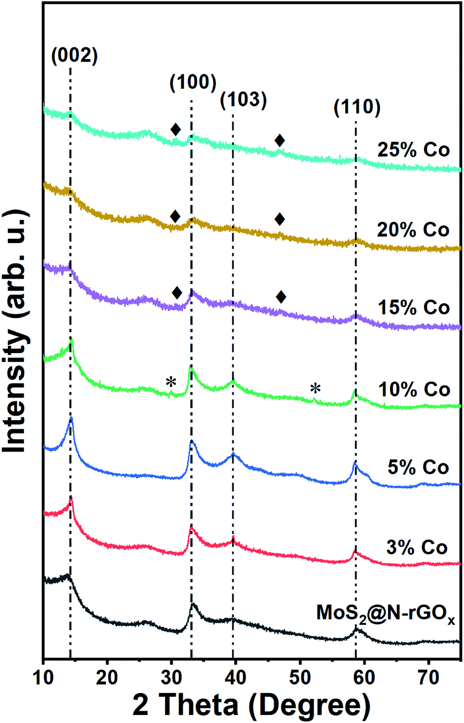 | ||
| Fig. 2 XRD patterns of pristine and Co–MoS2@N-rGOx. The vertical lines associated with 2H MoS2, peaks associated with cobalt sulfides are marked by * for features corresponding to Co9S8 and ♦ for Co1−xS. The weak peak at 26.0° corresponds to the (002) plane of graphite. | ||
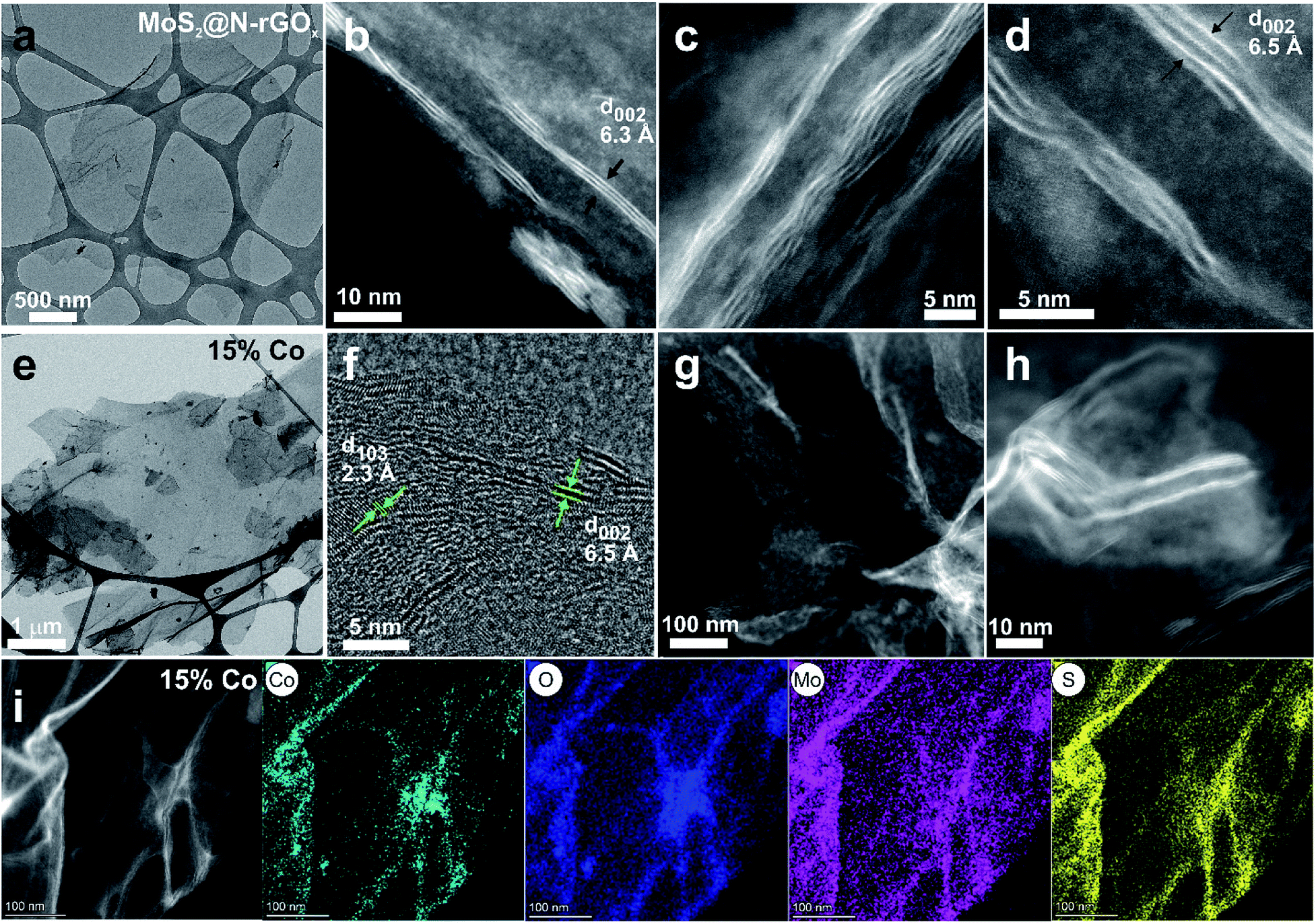 | ||
| Fig. 3 TEM and STEM-HAADF images of (a–d) MoS2@N-rGOx, and (e–h) 15% Co–MoS2@N-rGOx. (i) STEM-BF image and EDS elemental analysis of 15% Co–MoS2@N-rGOx. | ||
We continued our study with the addition of cobalt nitrate to form Co-doped MoS2 and investigated the effects of Co concentration in the formation of the CoMoS phase and CoSx. We prepared five distinct samples containing 3, 5, 10, 15, and 25 at% of cobalt relative to the metal content. After the microwave treatment, there were no major changes in the diffractogram (Fig. 2) at low cobalt concentration, suggesting that most of the cobalt was properly introduced into the MoS2 lattice, later identified as the CoMoS phase by Raman and XPS characterization. However, for concentrations above 10 at%, some weak features in the diffractogram appeared, indicating the presence of various cobalt sulfides. In particular, the 10% Co doped sample exhibits two peaks at 29.8° and 52.2° possibly corresponding to Co9S8 (crystal planes (311) and (440), JCPDS 75-2023), and for samples exceeding 15% another two new peaks at 30.6° and 46.8° formed that could be originated from the (100) and (102) planes of Co1−xS (JCPDS 42-0826). Nevertheless, the limited information is insufficient to properly identify the nature of the cobalt sulfide, but it suggests the coexistence of cobalt as dopant in MoS2 and as cobalt sulfide at large Co content. Another consequence of cobalt doping for samples above 15% is the significant reduction in peak intensity of features related to MoS2, this of course, can be related to the lower amount of Mo, and thus MoS2, but it also suggests the reduction in crystallite size caused by Co due to interruption of the MoS2 growth. The latter is typically observed in materials containing the CoMoS phase, as more Co occupy the edge sites in MoS2 limiting the crystal growth along the plane.9,10,36 The latter is also evidenced from SEM and TEM studies (Fig. 1b, 3e–h and S4†) where small flakes and particles are seen along the surface, in which these flakes gradually decrease in size with increasing amount of cobalt. In addition, we did not observe any significant segregation from EDS elemental mapping (Fig. 3, S6 and Table S1†) regardless of the cobalt doping, meaning that even if CoSx particles are formed, these are also homogeneously dispersed in the material. The shelf life of the samples was measured after storing them for 3 months at ambient conditions, and samples with large Co content, particularly ≥20%, exhibited signs of oxidation evidence by the appearance of new diffraction peaks in the XRD patterns (Fig. S7†). The new XRD features suggest the formation of partial oxides such as CoMoS2.17O1.12 (JCPDS 16-0438) and CoMoS2.96O0.25 (JCPDS 16-0105), fortunately, the oxidation process was not seen in other samples. Finally, we want to highlight a peculiar characteristic of samples doped with low Co content (5 and 10 at%), where we found several core–shell nanoparticles, see Fig. S8,† in which the shell is a layered material consistent with MoS2, while the core composition is unknown. The particle size was around 15-30 nm and the shell consisted of few MoS2 layers. These particles were rarely observed and they did not comprise the majority of the sample, complicating its study and characterization, however further optimization could potentially increase the yield allowing to properly investigate the properties of such core–shell particles.
Elemental composition and nature of cobalt doping
The evolution of the oxygen content was evaluated at different steps along the synthesis process, and we observed an increase from 2.41 at% for N-rGOx to 8.09 at% for non-doped MoS2@N-rGOx, (see XPS survey in Fig. S9 and Table S1†), and then a higher oxygen content was observed at large Co concentration, reaching 11.44 and 13.35 at% for samples with 15% and 25% of cobalt. However, no XRD features of metal oxides were observed, and in addition the oxygen homogeneously distributed along the sample as seen in the elemental mappings in Fig. 3i, S2 and S6†, suggest the formation of oxygenated groups, such as sulfates (SO4)2− as indicated later by XPS. We now focus on the 15% Co–MoS2@N-rGOx sample and its high resolution XPS spectra shown in Fig. 4. The XPS spectrum of O 1s is composed of three individual peaks at 530.5 eV, 531.7 eV, and 533.3 eV, these could originate from the lattice oxygen in Mo or Co oxides, as well as adsorbed oxygen moieties.37,38 As the amount of cobalt increases, the overall O 1s peak shifts toward higher energies (Fig. 4c and S10†) indicating a larger contribution from oxygen in metal oxides. On the other hand, large Co content downshifted both Mo 3d and S 2p peaks (Fig. 4 and S10†), as evidenced in Fig. 4a where the binding energies of the Mo 3d3/2 and 3d5/2 features corresponding to Mo(IV) (232.0/228.8 eV) are slightly lower than those in MoS2@N-rGOx (232.2/229.0 eV, Fig. S11†). This phenomenon is consistent with the lower effective nuclear charges of Mo and S compared to MoS2 corresponding to a reduction of the oxidation state. However, it is still possible to observe two other doublets at 235.3/232.2 eV and 232.9/229.7 eV that indicate the existence of Mo(VI) and Mo(V), respectively, the coexistence of all these features have been reported in materials with mixed sulfides and oxides, such as MoOxSy.39–42 In comparison, the non-doped MoS2@N-rGOx exhibits only features corresponding to Mo(IV) and Mo(VI). The deconvolution of S 2p spectra yielded three doublets for the S 2p3/2 and S 2p1/2, the first one (161.6/162.8 eV) is assigned to S2− in MoS2, the second one (162.9/164.0 eV) to nonstoichiometric MoSx, and the third one (168.2/169.4 eV) with a larger intensity when compared to the non-doped counterpart is related to sulfate moieties such as SO42−, which is in agreement with the increase in oxygen and cobalt content, probably forming Co and Mo sulfates.30,31,43,44 For the case of cobalt, the Co 2p spectrum can be resolved into two spin–orbit doublets and four satellites. The first doublet located at 778.8/793.7 eV is attributed to cobalt sulfides, while the doublet at 781.4/796.9 eV and all four satellites correspond to oxidized Co2+/Co3+,45,46 the latter increase in intensity only for samples with at least 15% Co, suggesting that at low Co content the vast majority is in the form of sulfides. All Co doped samples have a peak around 778.8 eV, that is close in binding energy to those observed in Co9S8,47 Co1−xS,48 and the CoMoS phase.49 We used the binding energy difference as proposed by Alstrup and coworkers13,49 to better understand the nature of cobalt doping. This method involves evaluating two binding energy differences ΔE1 and ΔE2, defined as E(Co 2p3/2) − E(S 2p3/2), and E(Mo 3d5/2) − E(S 2p3/2), respectively. In our case, we found ΔE1 = 617.2 eV and ΔE2 = 67.2 eV, which are in agreement with previously reported values for the CoMoS phase (ΔE1 = 617.0–616.0 eV, ΔE2 = 66.9–65.9 eV),13,50 indicating that the major contributing phase is CoMoS.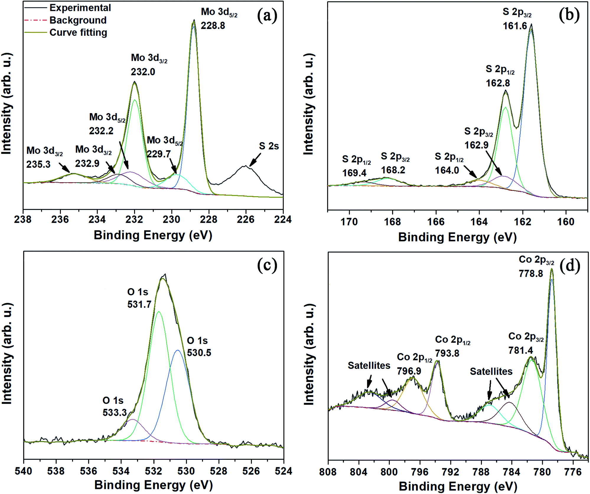 | ||
| Fig. 4 XPS spectra of (a) Mo 3d, (b) S 2p, (c) O 1s, and (d) Co 2p for the 15% Co–MoS2@N-rGOx. Detailed information can be found in the main text. | ||
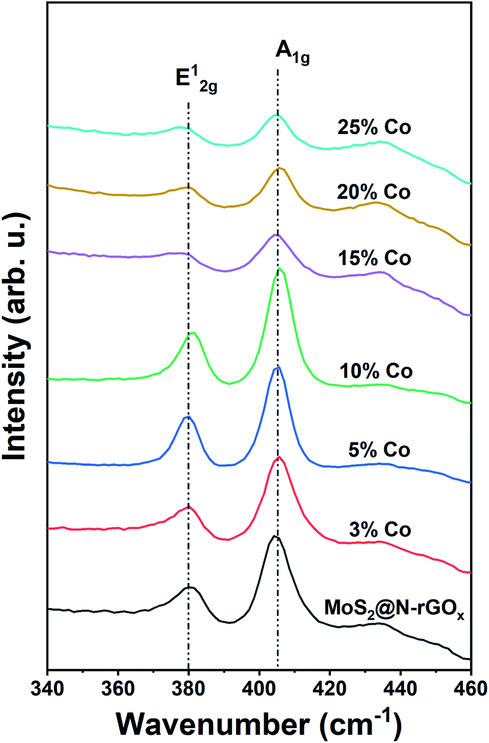
We used Raman spectroscopy to identify changes in the N-rGOx substrate as well as the 2H MoS2 caused by the addition of cobalt, initially we noticed that the ratio of the D and G bands (ID/IG) in graphene increased from 0.81 for rGOx (reduced under Ar/H2 at 750 °C) to 0.88 and then to 0.96 for N-rGOx and non-doped MoS2@N-rGOx respectively, see Fig. S12.† Indicating that in each subsequent process the graphitic lattice is disrupted, first by the nitrogen introduction, and then due to the decoration with MoS2, reinforcing the idea of a strong interaction within the metal chalcogenide and the substrate. The Raman spectra for the active region of MoS2 is depicted in Fig. 5. The two peaks located at 379.9 cm−1 and 405.3 cm−1 correspond to the in-plane E12g and out-of-plane A1g vibrational modes of the 2H MoS2. Both E12g and A1g features are red-shifted in comparison to bulk MoS2 (383 and 408 cm−1), similar red-shift has been observed in the presence of biaxial strain on free-standing MoS2 sheets.51 In our case, the abundance of defects and dopants could cause the biaxial strain and thus the observed shift. Additionally, Raman spectroscopy also indicates the abundance of edge-terminated structures as seen by the E12g/A1g integrated intensity ratio of ∼0.5 as expected for the CoMoS phase, since the A1g (E12g) mode is preferentially excited for edge- (terrace-) terminated layers,52,53 and so the Co-doped MoS2@N-rGOx exhibit, in general, large number of electrocatalytically active sites.
 | ||
| Fig. 5 Raman spectra of non-doped and Co-doped MoS2@N-rGOx. | ||
We also performed ab initio theoretical calculations to investigate the preferential doping sites of cobalt on a 2H MoS2 flake, we replaced individual Mo atoms by Co and then evaluated the relative formation energy (Eform) to identify stable doping configurations. The results are shown in Fig. 6 as a 2D map of the hexagonal MoS2 flake indicating the doping sites, while the color specifies the calculated Eform with negative values indicating preferable configurations. From the observed Eform is easier to understand the formation of the CoMoS phase, as Co will preferentially occupy the edge sites of MoS2 sheets with vertices being the most stable sites with Eform of around −3.5 eV, followed by both Mo- and S-edges (−3.0 to −1.5 eV). It is also clear that the Eform weakens significantly up to −0.5 eV (seen as green) for the first neighbors after the edge atoms, and then Eform is further reduced to values close to zero (relative to the bulk-like Co-doping energy) for the second neighbors and so on. These results have two main consequences, the first one being that Co will mostly occupy the Mo-sites at vertices and edges, and the second one that it will limit the crystal growth of MoS2 flakes exposing additional edge atoms.
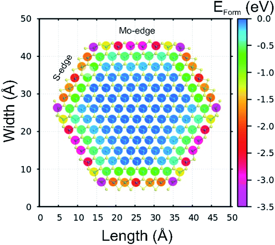 | ||
| Fig. 6 Relative formation energy (Eform) of cobalt atoms occupying diverse Mo sites along a single 2H MoS2 flake. The S-edges (Mo-edges) were passivated at 50% (100%). Negative values of Eform indicate preferable sites for cobalt doping. | ||
Hydrogen evolution performance
The hydrogen evolution reaction was investigated in acidic electrolyte (0.5 M H2SO4) using linear sweep voltammetry (LSV) in a three-electrode cell, the iR-compensated data is shown in Fig. 7. From the LSV studies, it is clear that all the Co-doped samples exhibited a smaller onset potential for HER catalysis than that of pristine MoS2@N-rGOx. It is also evident that there is a gradual improvement in the HER activity with increased amount of Co reaching a maximum at 15%. At larger Co concentration, the HER activity (measured as the overpotential to achieve 10 mA cm−2, η10) stalls, and a slight deterioration is observed. The resulting η10 is reduced from 238 mV for the non-doped MoS2@N-GOx to 197 mV for the 15% Co–MoS2@N-GOx, in agreement with previous CoMoS materials.9,10 The Tafel slope was evaluated by performing a linear fitting at the low current density region and it was found that non-doped and Co–MoS2@N-GOx exhibit similar Tafel slopes of 61 mV dec−1, indicating that in our case Co doping mainly decreased the onset potential and has little effect on the HER mechanism. The observed Tafel slope suggests that the HER occurs via the Volmer–Heyrovský mechanism where the adsorption of protons dominates the kinetics. Considering the fast synthesis process, our best sample exhibit comparable performance with other MoS2-based catalysts produced, for example, via solvothermal, exfoliation, or annealing methods, a detailed comparison is included in Table S2.† Electrochemical impedance spectroscopy studies prove that cobalt doping reduces the charge transfer resistance (Fig. 7c) from 55.2 Ω cm2 to 17.1 Ω cm2 for pristine and 15% Co-doped samples, respectively. The lower charge transfer resistance is attributed to the destabilization (reduced binding energy) of the Mo 3d orbital with increase Co content (Fig. S10a†), and thus improving the interaction with the N-rGOx substrate and facilitating the electron transport. The stability of the 15% Co–MoS2@N-GOx electrocatalyst was investigated by cyclic voltammetry (CV) by performing 5000 CV cycles within the range −0.15 V to +0.35 V (vs. RHE) at a scan rate of 100 mV·s−1. Fig. 7d depicts the initial and final polarization curves where no obvious degradation was observed. | ||
| Fig. 7 (a) Polarization curves of non-doped and Co–MoS2@N-rGOx, and 20% Pt@Vulcan (with iR compensation), (b) the corresponding Tafel plots. (c) Electrochemical impedance spectroscopy of MoS2@N-rGOx, 15% and 25% Co–MoS2@N-rGOx in 0.5 M H2SO4 at an overpotential of 150 mV, inset is the equivalent circuit. (d) Polarization curves of 15% Co–MoS2@N-rGOx before and after the durability test, the inset shows the 5000 CV cycles in the range of −0.15 to +0.35 V (vs. RHE). | ||
Conclusions
Two-dimensional few-layers MoS2 with a 2H crystal structure was grown directly on N-rGOx through a solid-state reaction using microwave irradiation lasting only 2 minutes. The as-produced MoS2 was 3–8 layer thick with a turbostratic distribution, and the addition of cobalt results in the formation of the CoMoS phase where few-layer Co–MoS2 nanosheets also cover the entire N-rGOx substrate. The presence of Co hinders the growth of fully continuous MoS2 layers, and thus the Co–MoS2 nanosheets are dominated by edge-terminated structures, leading to a high proportion of active site exposure and promoting efficient electron transfer. The HER activity was significantly improved for the 15% Co–MoS2@N-rGOx with a relatively low overpotential of 197 mV at 10 mA cm−2 and a Tafel slope of 61 mV dec−1. The catalyst also possessed good operational stability with no apparent degradation after 5000 CV cycles. In addition, as an effective synthesis technique, microwave irradiation is expected to play a more important role in the research of novel materials.Conflicts of interest
There are no conflicts to declare.Acknowledgements
E. G. E. and S.K. acknowledge support from the Swedish Research Council (2018-03937, 2019-05114) and the Olle Engkvist Foundation (186-0637). The authors acknowledge Umeå Core Facility for Electron Microscopy (UCEM) and the Vibrational Spectroscopy Core Facility (ViSp) at Umeå University, Chemical Biological Centre (KBC). Andrey Shchukarev and Andras Gorzsas at Umeå University, KBC, are acknowledged for the assistance with XPS and Raman measurements, respectively. The theoretical simulations were performed on resources provided by the Swedish National Infrastructure for Computing (SNIC) at the High Performance Computing Center North (HPC2N).References
- M. A. Lukowski, A. S. Daniel, F. Meng, A. Forticaux, L. Li and S. Jin, J. Am. Chem. Soc., 2013, 135, 10274–10277 CrossRef CAS PubMed.
- J. Tang, M. Sakamoto, H. Ohta and K. Saitow, Nanoscale, 2020, 12, 4352–4358 RSC.
- J. Hu, B. Huang, C. Zhang, Z. Wang, Y. An, D. Zhou, H. Lin, M. K. H. Leung and S. Yang, Energy Environ. Sci., 2017, 10, 593–603 RSC.
- X. Hai, W. Zhou, S. Wang, H. Pang, K. Chang, F. Ichihara and J. Ye, Nano Energy, 2017, 39, 409–417 CrossRef CAS.
- T. Huang, J. Xu and Y. Fan, Appl. Catal., B, 2018, 220, 42–56 CrossRef CAS.
- Y. Wu, M. Zarei-Chaleshtori, B. Torres, T. Akter, C. Diaz-Moreno, G. B. Saupe, J. A. Lopez, R. R. Chianelli and D. Villagrán, Int. J. Hydrogen Energy, 2017, 42, 20669–20676 CrossRef CAS.
- X. Hong, K. Chan, C. Tsai and J. K. Nørskov, ACS Catal., 2016, 6, 4428–4437 CrossRef CAS.
- P. Li, Y. Yang, S. Gong, F. Lv, W. Wang, Y. Li, M. Luo, Y. Xing, Q. Wang and S. Guo, Nano Res., 2019, 12, 2218–2223 CrossRef CAS.
- S. S. Grønborg, M. Šarić, P. G. Moses, J. Rossmeisl and J. V. Lauritsen, J. Catal., 2016, 344, 121–128 CrossRef.
- X. Dai, K. Du, Z. Li, M. Liu, Y. Ma, H. Sun, X. Zhang and Y. Yang, ACS Appl. Mater. Interfaces, 2015, 7, 27242–27253 CrossRef CAS.
- A. M. de Jong, V. H. J. (San) de Beer, J. A. Rob van Veen and J. W. (Hans) Niemantsverdriet, J. Vac. Sci. Technol., A, 1997, 15, 1592–1596 CrossRef CAS.
- N. Zhang, W. Ma, F. Jia, T. Wu, D. Han and L. Niu, Int. J. Hydrogen Energy, 2016, 41, 3811–3819 CrossRef CAS.
- R. Bose, Z. Jin, S. Shin, S. Kim, S. Lee and Y.-S. Min, Langmuir, 2017, 33, 5628–5635 CrossRef CAS.
- J. Deng, H. Li, J. Xiao, Y. Tu, D. Deng, H. Yang, H. Tian, J. Li, P. Ren and X. Bao, Energy Environ. Sci., 2015, 8, 1594–1601 RSC.
- D. Vollath and D. V. Szabó, Mater. Lett., 1998, 35, 236–244 CrossRef CAS.
- D. H. Youn, J. W. Jang, J. Y. Kim, J. S. Jang, S. H. Choi and J. S. Lee, Sci. Rep., 2014, 4, 1–8 Search PubMed.
- S. Balaji, D. Mutharasu, N. Sankara Subramanian and K. Ramanathan, Ionics, 2009, 15, 765–777 CrossRef CAS.
- K. Z. Du, A. Chaturvedi, X. Z. Wang, Y. Zhao, K. K. Zhang, M. Iqbal Bakti Utama, P. Hu, H. Jiang, Q. H. Xiong and C. Kloc, Dalton Trans., 2015, 44, 13444–13449 RSC.
- H. J. Kitchen, S. R. Vallance, J. L. Kennedy, N. Tapia-Ruiz, L. Carassiti, A. Harrison, A. G. Whittaker, T. D. Drysdale, S. W. Kingman and D. H. Gregory, Chem. Rev., 2014, 114, 1170–1206 CrossRef CAS PubMed.
- R. Sandström, E. Gracia-Espino, G. Hu, A. Shchukarev, J. Ma and T. Wågberg, Nano Energy, 2018, 46, 141–149 CrossRef.
- H. Shen, E. Gracia-Espino, L. Wang, D. Qin, S. Gao, X. Mamat, W. Ren, T. Wågberg and G. Hu, Electrochem. Commun., 2017, 81, 116–119 CrossRef CAS.
- R. Sandström, J. Ekspong, E. Gracia-Espino and T. Wågberg, RSC Adv., 2019, 9, 17979–17987 RSC.
- M. H. Suliman, A. Adam, M. N. Siddiqui, Z. H. Yamani and M. Qamar, Carbon, 2019, 144, 764–771 CrossRef CAS.
- D. C. Marcano, D. V. Kosynkin, J. M. Berlin, A. Sinitskii, Z. Sun, A. Slesarev, L. B. Alemany, W. Lu and J. M. Tour, ACS Nano, 2010, 4, 4806–4814 CrossRef CAS PubMed.
- G. Speranza, L. Minati and M. Anderle, J. Appl. Phys., 2007, 102, 043504 CrossRef.
- P. R. Kidambi, B. C. Bayer, R. Blume, Z.-J. Wang, C. Baehtz, R. S. Weatherup, M.-G. Willinger, R. Schloegl and S. Hofmann, Nano Lett., 2013, 13, 4769–4778 CrossRef CAS PubMed.
- B. Hammer, L. B. Hansen and J. K. Nørskov, Phys. Rev. B, 1999, 59, 7413–7421 CrossRef.
- J. M. Soler, E. Artacho, J. D. Gale, A. García, J. Junquera, P. Ordejón and D. Sánchez-Portal, J. Phys.: Condens. Matter, 2002, 14, 2745–2779 CrossRef CAS.
- J. Junquera, Ó. Paz, D. Sánchez-Portal and E. Artacho, Phys. Rev. B, 2001, 64, 235111 CrossRef.
- J. Ekspong, R. Sandström, L. P. Rajukumar, M. Terrones, T. Wågberg and E. Gracia-Espino, Adv. Funct. Mater., 2018, 28, 1802744 CrossRef.
- J. Ekspong, T. Sharifi, A. Shchukarev, A. Klechikov, T. Wågberg and E. Gracia-Espino, Adv. Funct. Mater., 2016, 26, 6766–6776 CrossRef CAS.
- S. Iqbal, Z. Pan and K. Zhou, Nanoscale, 2017, 9, 6638–6642 RSC.
- K. Chang, M. Li, T. Wang, S. Ouyang, P. Li, L. Liu and J. Ye, Adv. Energy Mater., 2015, 5, 1402279 CrossRef.
- M. Poisot, W. Bensch, S. Fuentes, C. Ornelas and G. Alonso, Catal. Lett., 2007, 117, 43–52 CrossRef CAS.
- D. L. Bish and J. E. Post, Modern Powder Diffraction, De Gruyter, Berlin, Boston, 1989 Search PubMed.
- H. Topsøe, B. S. Clausen, R. Candia, C. Wivel and S. Mørup, J. Catal., 1981, 68, 433–452 CrossRef.
- R. D. Nikam, P. A. Sonawane, R. Sankar and Y. T. Chen, Nano Energy, 2017, 32, 454–462 CrossRef CAS.
- L. Stobinski, B. Lesiak, A. Malolepszy, M. Mazurkiewicz, B. Mierzwa, J. Zemek, P. Jiricek and I. Bieloshapka, J. Electron Spectrosc. Relat. Phenom., 2014, 195, 145–154 CrossRef CAS.
- X. Shao, J. Tian, Q. Xue and C. Ma, J. Mater. Chem., 2003, 13, 631–633 RSC.
- J. Qiu, Z. Yang and Y. Li, J. Mater. Chem. A, 2015, 3, 24245–24253 RSC.
- L. Benoist, D. Gonbeau, G. Pfister-Guillouzo, E. Schmidt, G. Meunier and A. Levasseur, Solid State Ionics, 1995, 76, 81–89 CrossRef CAS.
- N. Salazar, I. Beinik and J. V. Lauritsen, Phys. Chem. Chem. Phys., 2017, 19, 14020–14029 RSC.
- J. Dolinska, A. Chidambaram, W. Adamkiewicz, M. Estili, W. Lisowski, M. Iwan, B. Palys, E. J. R. Sudholter, F. Marken, M. Opallo and L. Rassaei, J. Mater. Chem. B, 2016, 4, 1448–1457 RSC.
- N. Liu, J. Baek, S. M. Kim, S. Hong, Y. K. Hong, Y. S. Kim, H. S. Kim, S. Kim and J. Park, ACS Appl. Mater. Interfaces, 2017, 9, 42943–42950 CrossRef CAS PubMed.
- B. Liu, S. Wei, Y. Xing, D. Liu, Z. Shi, X. Liu, X. Sun, S. Hou and Z. Su, Chem.–Eur. J., 2010, 16, 6625–6631 CrossRef CAS PubMed.
- H. Lin, H. Li, Y. Li, J. Liu, X. Wang and L. Wang, J. Mater. Chem. A, 2017, 5, 25410–25419 RSC.
- X. Zheng, J. Guo, Y. Shi, F. Xiong, W.-H. Zhang, T. Ma and C. Li, Chem. Commun., 2013, 49, 9645 RSC.
- C. Dong, L. Guo, Y. He, L. Shang, Y. Qian and L. Xu, Nanoscale, 2018, 10, 2804–2811 RSC.
- I. Alstrup, I. Chorkendorff, R. Candia, B. S. Clausen and H. Topsøe, J. Catal., 1982, 77, 397–409 CrossRef CAS.
- H. Zhang, Y. Li, T. Xu, J. Wang, Z. Huo, P. Wan and X. Sun, J. Mater. Chem. A, 2015, 3, 15020–15023 RSC.
- N. Scheuschner, O. Ochedowski, A.-M. Kaulitz, R. Gillen, M. Schleberger and J. Maultzsch, Phys. Rev. B: Condens. Matter Mater. Phys., 2014, 89, 125406 CrossRef.
- J. L. Verble and T. J. Wieting, Phys. Rev. Lett., 1970, 25, 362–365 CrossRef CAS.
- D. Kong, H. Wang, J. J. Cha, M. Pasta, K. J. Koski, J. Yao and Y. Cui, Nano Lett., 2013, 13, 1341–1347 CrossRef CAS.
Footnote |
| † Electronic supplementary information (ESI) available. See DOI: 10.1039/d0ra05560c |
| This journal is © The Royal Society of Chemistry 2020 |