DOI:
10.1039/D0RA05044J
(Paper)
RSC Adv., 2020,
10, 34187-34196
An amine-bifunctionalization strategy with Beta/KIT-6 composite as a support for CO2 adsorbent preparation
Received
8th June 2020
, Accepted 10th September 2020
First published on 15th September 2020
Abstract
An amine-bifunctionalized composite strategy was used to fabricate grafted-impregnated micro-/mesoporous composites for carbon dioxide capture. The micro-/mesoporous Beta/KIT-6 (BK) composite containing a high-silica zeolite with a three-dimensional twelve-membered ring crossing channel system and cubic structural silica was used as a support, and 3-aminopropyltrimethoxysilane (APTS) and tetraethylenepentamine (TEPA) were used as the grafted and impregnated components, respectively. The amine efficiency, adsorption kinetics, thermal stability, regeneration performance, and the effects of impregnated amine loadings (30–60%) and temperatures (40–90 °C) on the CO2 adsorption performance were investigated using a thermal gravimetric analyzer (TGA) in the mixed gases (15 vol% CO2 and 85 vol% N2). At 60 °C, the bifunctionalized Beta/KIT-6 (1 mL APTS g−1 BK) displayed the highest CO2 adsorption capacity of 5.12 mmol g−1 at a TEPA loading of 50%. The kinetic model fitting results showed that the CO2 adsorption process was a combination of physical and chemical adsorption, wherein the chemical adsorption is dominant. After five adsorption/desorption cycle regenerations, the saturated adsorption capacity of the composite material was 4.86 mmol g−1, which was only 5.1% lower than the original adsorption capacity. The composites demonstrated excellent CO2 adsorption performance, indicating the promising future of these adsorbents for CO2 capture from actual flue gas after desulfurization.
Introduction
Global warming and extreme weather occurrences are caused by the rapid increase of greenhouse gases (GHGs) in the atmosphere.1 Among them, the main reason for the large amount of CO2 emitted into the atmosphere is the high demand for fossil fuels (coal, oil, natural gas).2 Carbon dioxide capture and storage (CCS) technology is an effective way for CO2 emission reduction.3 Absorption of aqueous solutions of amines,4 porous material adsorption,5 cryogenic distillation,6 and membrane separation7 are the main methods of CO2 recovery. Solid adsorption has been regarded as one of the most promising CO2 capture methods due to the advantages of high CO2 selectivity, renewable cycle performance, rapid rate of adsorption/desorption, low price and little corrosion.8 The solid adsorbents commonly used in CO2 capture include carbon-based materials,9 zeolite molecular sieves,10 metal–organic frameworks (MOFs)11 and hydrotalcites.12 According to the study of Abanades et al., it can be calculated that the cost of removing CO2 from zeolites is the lowest, compared with monoethanolamine and active carbons.13 As CO2 adsorbents, the microporous zeolite molecular sieves mainly consist of 13X,14 Beta,15 ZSM-5,16 Y-type17 and MER-type,18 while the mesoporous molecular sieves include MCM series,19 SBA series,20 and KIT series.21 Microporous zeolite has excellent stability but small pore size, which leads to slow molecular escape rate;22 the pore wall of mesoporous molecular sieves with large pore size is thin and non-crystalline, and may collapse at high temperature.23 Therefore, the preparation of dual structural micro-/mesoporous composite molecular sieves has attracted the attention of researchers. Guo et al. synthesized the Beta/MCM-41 composite through a “two-step method” crystallization process combining a low crystalline Beta zeolite synthetic gel with CTAB, and the result showed that the composite possessed a well-ordered mesoporous MCM-41 phase and a Beta zeolite phase.24 Using hydrothermal crystallization, Zhang et al. fabricated the composite material Y/MCM-48 with significantly improved thermal stability and acidity.25 At the same time, in order to further improve the adsorption performance of CO2, amino-modified zeolite materials have attracted more and more scholars' attention, and the common modification methods of amino-group are divided into impregnation26 and grafting.27 Grafting modified molecular sieves can avoid the high reaction temperature required for the water removal and improve the selectivity and thermal stability of CO2, however, the number of amino groups introduced is less than that of the impregnation method. Therefore, researchers have combined the two methods in recent years. Wang et al. impregnated various amounts of TEPA onto the MCM-41 grafted by APTS and found that the new adsorbent could promote CO2 adsorption, with the maximum adsorption capacity of 3.5 mmol g−1.28 Sanz-Pérez et al. impregnated TEPA, polyethyleneimine (PEI) and piperazine (PZ) on the SBA-15 modified by APTS grafting, respectively.29 The results showed that the CO2 adsorption capacity of TEPA impregnated carrier was higher than that of carrier with better cycling stability. At 45 °C and 1 atm, the corresponding adsorption capacity was 2.4 mmol g−1 and the amine efficiency was 0.32 mol CO2 mol−1 N. At present, the CO2 adsorption by amine-bifunctionalized micro-/mesoporous composite molecular sieves is still at the exploratory stage, and the combination of molecular sieves with different pore sizes, organic amine's types, amine efficiency and cyclic stability of the materials are all research hotspots. Beta is a kind of high-silicon zeolite with three-dimensional twelve-membered ring crossing channel system. Compared with 1D arranged MCM-41 and 2D arranged SBA-15, KIT-6 with 3D pore arrangement exhibits the distinct mass transfer performance because of its large pore diameter as well as pore volume.30 In this work, Beta/KIT-6 composite was prepared by post synthesis, while APTS and TEPA were grafted and impregnated on Beta/KIT-6, respectively, using the “two-step method”, which has not been reported for CO2 adsorption. Characteristics of composite Beta/KIT-6, APTS-Beta/KIT-6 and APTS-Beta/KIT-6-TEPA, and the adsorption mechanism of CO2 were investigated. The adsorption performance test of CO2 was carried out in the simulated flue gas conditions of 60 °C and 15 vol% CO2.
Experimental
Preparation of support
For the Beta microporous molecular sieve, 29.45 g tetraethyl ammonium hydroxide (TEAOH, 25 wt%, Aladdin Industrial Co., Shanghai, China) and 21.43 g tetraethyl orthosilicate (TEOS, Aladdin Industrial Co., Shanghai, China) were stirred well at room temperature (350 rpm). The mixed solution was designated as S1. 0.19 g sodium hydroxide (NaOH, Aladdin Industrial Co., Shanghai, China), 0.76 g sodium metaaluminate (NaAlO2, Aladdin Industrial Co., Shanghai, China), 3.5 g TEAOH, and 2 g deionized water (H2O) were mixed and stirred in a beaker until dissolved, and the mixed solution was designated as S2. Then, S2 was added dropwise to S1 and stirred for 4 h until the sol formed was no longer delaminated. The Beta molecular sieve was obtained by high-pressure reaction (140 °C, 24 h), centrifugal separation, drying (80 °C, 10 h) and calcination (550 °C, 6 h). Under atmospheric pressure, the typical post synthesis method was used to synthesize the Beta/KIT-6 composite molecular sieve.31 First, for the KIT-6, 4 g P123 (Aladdin Industrial Co., Shanghai, China) and 6.7 mL HCl (AR, Sinopharm Chemical Reagent Co., Ltd, Shanghai, China) were dissolved in 144 mL H2O and stirred at 35 °C for 2 h until P123 dissolves completely. Next, 4.94 mL BuOH (Xilong Chem. Reagent Co., Shantou, China) were added in a slow drip and then stirred for 1 h; 9.24 mL TEOS were added to the solution, and stirred at a 40 °C for 24 h. Then, the pure KIT-6, was obtained by hydrothermal reaction (100 °C, 24 h), vacuum suction filtration, drying (100 °C, 24 h) and calcination (550 °C, 6 h).32 Second, for the Beta/KIT-6 composite molecular sieve, which was recorded as BK, according to the above production steps of KIT-6, after P123 was completely dissolved, 1.5 g Beta molecular sieve prepared in advance were added and stirred for 1 h, and the rest of the steps were the same.
Preparation of amine bifunctionalized samples
APTS was anchored onto the BK support by grafting. The typical grafted step carried out was depicted as follows.33 1 mL APTS (Aladdin Industrial Co., Shanghai, China) was added in 100 mL toluene followed by addition of 1 g BK support. Then, the mixture was heated to 85 °C under reflux for 16 h, filtered, washed with toluene, and dried at 100 °C for 2 h. The grafted sample was denoted as A-BK-1.
TEPA was anchored onto the A-BK-1 support by impregnating.34 A certain amount of TEPA (Sinopharm Chemical Reagent Co., Ltd, Shanghai, China) and 0.5 g A-BK-1 were dispersed in 25 mL ethanol and stirred at room temperature (400 rpm, 5 h). After evaporation (80 °C, 8 h) to remove ethanol, the bifunctionalized samples were obtained by drying in a natural convection oven at 100 °C for 1 h, which were referred to A-BK-TEPA-X (X = 30, 50, 55 or 60), where X stands for mass fraction of TEPA. For instance, A-BK-TEPA-30 indicates that the grafted sample A-BK was further loaded with 30 wt% TEPA.
Experimental method
The adsorption capacity of CO2 on samples was determined by the SDT Q600 thermal gravimetric analyzer (TA, USA). Inlet gas was a mixture of 15 vol% CO2 (99.999%) and 85 vol% N2 (99.999%). Before the adsorption, the thermal gravimetric analyzer needed to be preheated for 1 h. Then a certain amount of A-BK-TEPA-X was heated up to 110 °C in a nitrogen atmosphere at a heating rate of 10 °C min−1 and kept 40 min to remove the water vapor and other impurity gases to get a constant weight. When the sample temperature recorded by TGA decreased to adsorption temperature (40, 60, 75, 80 and 90 °C), the CO2/N2 mixed gases were entered until the sample quantity did not change. Finally, the adsorption capacities of samples were calculated using the eqn (1):| |  | (1) |
where qe is the saturated adsorption capacity of CO2 (mmol g−1); me and md are the weight of adsorption saturated and dewatered adsorbent (mg), respectively; 44.01 is the molar mass of CO2 (g mol−1). The cyclic performance of the sample was tested as follows. A certain amount of adsorbent was heated up to 110 °C in a nitrogen atmosphere at a heating rate of 10 °C min−1 and kept 40 min to remove the water vapor and other impurity gases to get a constant weight. As cooling to 60 °C, the CO2/N2 mixed gases were entered until the sample quantity did not change. The cycle was carried out for five times to explore the cyclic performance.
Characterization of samples
X-ray diffraction (XRD) tests were carried out with an X'Pert PRO powder diffractometer (PANalytical, Holland) using Cu-Kα radiation (40 kV and 40 mA) in 2θ range of 0.6–5° and 5–80°. The morphology of each sample was obtained by scanning electron microscopy (SEM) with a scanning electron microscope (Carl Zeiss, Germany) under accelerating voltage of 10 kV. Fourier transform infrared spectra (FTIR) were detected with a Nexus 470 IR spectrometer (Nicolet, USA) in wavenumber interval of 4000–400 cm−1. Detected wafers were made by mixing the samples and KBr with a mass radio of 1![[thin space (1/6-em)]](https://www.rsc.org/images/entities/char_2009.gif) :
:![[thin space (1/6-em)]](https://www.rsc.org/images/entities/char_2009.gif) 200. Thermal gravimetric and relevant differential analysis (TGA/DTG) was performed on a SDT Q600 TGA (TA, USA) in nitrogen flow up to 800 °C for A-BK-TEPA-X. The nitrogen contents of the samples were detected by EA 2400 II elemental analyzer (Perkin-Elmer, USA), and the average value of three experiments was taken as the test result. Nitrogen adsorption/desorption tests were carried out at −196 °C with a JW-BK200C automatic surface analyzer (JWGB Sci & Tech, Beijing). Each sample was outgassed at 100 °C in vacuum atmosphere for 10 h before test. The surface area was calculated by Brunauer–Emmett–Teller (BET). Total pore volume was calculated from N2 adsorption capacity at P/P0 = 0.99. Pore size distribution of mesopore was derived from adsorption branch of N2 curve using Barrett–Joyner–Halenda (BJH) method.
200. Thermal gravimetric and relevant differential analysis (TGA/DTG) was performed on a SDT Q600 TGA (TA, USA) in nitrogen flow up to 800 °C for A-BK-TEPA-X. The nitrogen contents of the samples were detected by EA 2400 II elemental analyzer (Perkin-Elmer, USA), and the average value of three experiments was taken as the test result. Nitrogen adsorption/desorption tests were carried out at −196 °C with a JW-BK200C automatic surface analyzer (JWGB Sci & Tech, Beijing). Each sample was outgassed at 100 °C in vacuum atmosphere for 10 h before test. The surface area was calculated by Brunauer–Emmett–Teller (BET). Total pore volume was calculated from N2 adsorption capacity at P/P0 = 0.99. Pore size distribution of mesopore was derived from adsorption branch of N2 curve using Barrett–Joyner–Halenda (BJH) method.
Results and discussion
XRD and SEM characterization
The XRD patterns of KIT-6, Beta, BK and A-BK-1 are presented in Fig. 1. As shown in the small-angle XRD pattern of the synthetic material (Fig. 1a), KIT-6 shows a sharp diffraction peak at 2θ = 0.88°, and a shoulder peak after it, corresponding to the (211) and (220) crystal planes of the three-dimensional cubic system.35 A series of weak peaks of KIT-6 at 2θ = 1.2–2°, correspond to (321), (400), (420) and (332) crystal planes. It is clear that the prepared KIT-6 has an ordered three-dimensional cubic mesoporous structure.36 The composite molecular sieve BK shows the same characteristic peaks as KIT-6, but the intensity of each peak is weakened, which shows that the order of the mesoporous structure of BK decreases. As seen from the wide-angle XRD pattern of the synthetic material (Fig. 1b), the sharp peaks at the degrees of 7.6 and 22.4 in the patterns of all samples are typical reflection of Beta zeolite.37 The BK and A-BK-1 show a lower intensity in the characteristic peaks compared with Beta because of the existence of KIT-6 phase. In addition, it is possible that the lower crystallinity of zeolite beta in BK is due to the structure degradation in HCl medium. This reason should not be ignored either. These results indicated the well combination of dual pore structures in the composites. Besides, modified by APTS, the mesoporous and microporous structures of BK were not destroyed, but the degree of order decreased. SEM images of Beta, KIT-6, BK and A-BK-1 are shown in Fig. 2. Spherical Beta zeolites with rough surfaces and loose uniform particles were observed (Fig. 2a), whereas KIT-6 displayed smooth surface and the appearance of a bent rod (Fig. 2b). It can be seen the irregular morphology of BK with spherical particles on the surface (Fig. 2c), which was mainly due to the inclusion of Beta microporous molecular sieve into the mesoporous material skeleton, resulting in the uneven grain growth. Fig. 2d shows the BK modified by APTS. Organic amine was loaded onto the carrier, so that the pore channel was filled and the pores between the particles were reduced. However, a certain amount of residual pores still existed, providing a channel for the adsorption and diffusion of CO2.
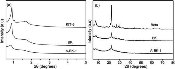 |
| | Fig. 1 (a) Small-angle and (b) wide-angle XRD patterns of KIT-6, Beta, BK and A-BK-1. | |
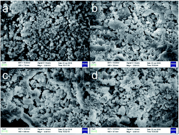 |
| | Fig. 2 SEM diagrams of (a) microporous Beta, (b) mesoporous KIT-6, (c) BK and (d) A-BK-1. | |
FTIR analysis
The FTIR spectra of BK, A-BK-1, A-BK-TEPA-30 and A-BK-TEPA-50 are shown in Fig. 3. All materials showed a broad band near 3467 cm−1 due to the physically absorbed water and the stretching vibrations of Si–O.38 Besides, a sharp band around 1638 cm−1 was found, which was due to bending vibration of identical bond as H2O described above.39 The bending and symmetric stretching vibration peaks of Si–O–Si in the skeleton were the peaks at 458 cm−1 and 790 cm−1, respectively, and the anti-symmetric stretching was shown at 1072 cm−1.40 The absorption peaks at 520 cm−1 and 570 cm−1 were typical characteristic vibration peaks of Beta zeolite five-membered ring and six-membered ring.37 After APTS modification, the peak intensity of adsorbed water at 1630 cm−1 of BK was weakened, because of the methoxy group in APTS reacting with Si–OH to form Si–O–Si bond.41 The peaks of the amine bifunctionalized BK at 2963 cm−1 and 2856 cm−1 were the stretching vibration peaks of the C–H bond on the CH2 and CH3 groups in the modifier.42 The bending vibration peaks of C–H bond and –NH2 were shown at 1482 cm−1 and 1569 cm−1, respectively, and the stretching vibration peak of C–N bond was 1316 cm−1.43 Compared with the BK modified by grafting alone, it can be seen that with the increase of TEPA impregnation, the peaks at 1482 cm−1 and 2963 cm−1 were significantly enhanced, and the peak at 1630 cm−1 of physically adsorbed water was also enhanced, which was mainly due to the introduction of TEPA improving the ability of the materials to adsorb water. Infrared analysis results showed that TEPA was successfully loaded onto BK grafted by APTS and the modified material and CO2 mainly react as follows:| | | CO2 + 2RNH2 → RNHCOO− + RNH3+ | (2) |
| | | CO2 + 2R1R2NH → R1R2NCOO− + R1R2NH2+ | (3) |
| | | CO2 + R2NH + RNH2 → R2NCOO− + RNH3+ (or RNHCOO− + R2NH2+) | (4) |
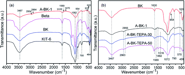 |
| | Fig. 3 FTIR spectra of (a) Beta, KIT-6, BK, A-BK-1 and (b) A-BK-TEPA-30 and A-BK-TEPA-50. | |
TGA/DTG studies
The thermal stability of composite was determined from the weight loss and the rate of weight loss of the material by TGA/DTG analysis methods for the feasibility of using composite at flue gas temperature. The TGA weight loss curves and the corresponding DTG curves of bifunctionalized BK are shown in Fig. 4. For A-BK-TEPA-X, the first obvious weight loss below 120 °C was attributed to the impurity gases, physically adsorbed water and residual solvents in the synthesis process (Fig. 4b). The subsequent two stages of weight loss were mainly caused by the decomposition-volatilization of TEPA and APTS and the dehydration of silicon hydroxyl molecules. The materials reach the peak decomposition rate at about 200 °C and the mass variation is no longer obvious after 550 °C. With the same APTS grafting amount, when the TEPA impregnation content increases, the mass loss gradually increases, the intensity of second weightlessness peak slightly increases, and the stability of materials decreases. With impregnating 30%, 50%, 55% and 60% TEPA, the weight losses of the materials were 31%, 48%, 55% and 65%, respectively (Fig. 4a). These weight loss values were all lower than the theoretical value, mainly because APTS and TEPA were not fully loaded on BK during the bifunctionalization process. After filtering or drying, some organic amines were detached from the carrier surface. It can be seen at the TGA/DTG results that the initial decomposition temperature of A-BK-TEPA-X was 150 °C, and the double functionalized BK materials can stably exist in the range of adsorption/desorption test temperature (∼110 °C).
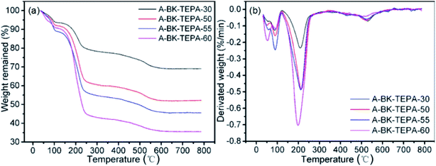 |
| | Fig. 4 TGA curves and DTG curves of A-BK-TEPA-X. | |
N2 adsorption/desorption studies
The N2 adsorption/desorption isotherms of the bifunctionalized BK materials and pore size distribution of KIT-6, BK and A-BK-1 were shown in Fig. 5, and the pore structure data of the material were summarized in Table 1. In Fig. 5a and b, KIT-6, BK, A-BK-1 belonged to the type IV isotherm, showing the type H1 hysteresis ring, which conformed to the adsorption characteristics of mesoporous structure.44 Beta belonged to the type I isotherm, which was the adsorption characteristic curve of microporous materials. The hysteresis loop height of KIT-6 was higher than that of BK, indicating that its pore volume was larger than that of BK. The results were consistent with the data in Table 1. With the increase of TEPA impregnation amount, the N2 adsorption/desorption isotherm of the composite material BK gradually decreased, and the hysteresis loop also gradually shrank to disappear. The reason was that as the load increased, the amino groups loaded onto the pores and surfaces of BK increased, resulting in the decrease of pore size and N2 adsorbed amount, the disappearance of hysteresis rings, and the pores filling. In Fig. 5c, the pore diameter distribution of KIT-6 was mainly concentrated around 9.84 nm, while the pore diameter distribution of BK was mainly concentrated around 8.56 nm. This was mainly due to the post-synthesis method adopted in this experiment, Beta micropore zeolite was imbedded into the pore channels of the mesoporous molecular sieve KIT-6, resulting in the decrease of pore diameter. However, zeolite Beta does not have mesoporous pore size, which indicated that the prepared composite BK had ordered mesoporous pore channels. In addition, due to the presence of zeolite Beta, the concentration of the pore diameter distribution and pore size of BK materials decreased. After grafting BK with APTS, organic amines were loaded onto the pores and surfaces of the material, blocking some of the pores and making the materials aperture smaller. From the data in Table 1, with the increase of the amino loading capacity, the specific surface area and pore volume of the dual-functional materials decreased rapidly, from 96.6 to 9.6 m2 g−1 and 0.24 to 0.01 cm3 g−1, respectively. Besides, the nitrogen content of the BK samples increased from 8.74 to 15.35 mmol g−1, whereas the amine efficiency (calculated from eqn (5)) increased first and then decreased.| |  | (5) |
where nCO2 is saturated adsorption capacity of CO2, mmol g; nN is the molar content of element N, mmol g−1.
 |
| | Fig. 5 (a) and (b) N2 adsorption/desorption isotherms and (c) pore size distribution of adsorbents. | |
Table 1 Physical properties, nitrogen contents, CO2 adsorption capacities and amine efficiencies of adsorbents at 60 °C
| |
Pore volume (cm3 g−1) |
Surface area (m2 g−1) |
Mesoporous diameter (nm) |
N content (mmol g−1) |
CO2 adsorption capacity (mmol g−1) |
Amine efficiency (mmol CO2 mmol−1 N) |
| KIT-6 |
1.42 |
718.5 |
9.84 |
— |
— |
— |
| BK |
1.13 |
655.1 |
8.56 |
— |
— |
— |
| Beta |
0.49 |
545.7 |
— |
— |
— |
— |
| A-BK-1 |
0.37 |
120.3 |
5.98 |
5.85 |
2.46 |
0.42 |
| A-BK-TEPA-30 |
0.24 |
96.6 |
— |
8.74 |
3.78 |
0.43 |
| A-BK-TEPA-50 |
0.09 |
50.2 |
— |
11.39 |
5.12 |
0.45 |
| A-BK-TEPA-55 |
0.07 |
34.7 |
— |
12.75 |
4.46 |
0.35 |
| A-BK-TEPA-60 |
0.01 |
9.6 |
— |
15.35 |
4.01 |
0.26 |
Adsorption performance of samples
The CO2 adsorption curves of A-BK-TEPA-X at 60 °C are shown in Fig. 6 (inlet CO2 concentration = 15 vol%, gas flow rate = 60 cm3 min−1). Under the constant grafting amount of APTS, with increasing TEPA loading, the CO2 adsorption capacity increased first and then decreased. Amino functional groups could react with CO2, theoretically the higher the load of impregnated amino group, the higher the adsorption capacity of CO2. However, excessive amino loading on the composite material BK would cause the obstruction of the carrier channel, reduced the specific surface area and pore volume of the materials, hindered the diffusion of CO2 in the material channel and the amino reaction in the pore,45,46 and reduced the CO2 adsorption ratio to the optimal value. The CO2 saturated adsorption capacity of bifunctionalized adsorbents, A-BK-TEPA-30, A-BK-TEPA-50, A-BK-TEPA-55 and A-BK-TEPA-60, were 3.78, 5.12, 4.46 and 4.01 mmol g−1, respectively, and the maximum adsorption capacity was obtained for A-BK-TEPA-50. As an alkanolamine, when APTS was grafted onto a BK carrier, it can provide large amounts of –NH2 adsorption sites. In addition, the silicon hydroxyl groups on BK can react with APTS to form the Si–O–Si network structures, which promoted the dispersion of TEPA, making TEPA more uniformly dispersed in the pores of carriers and providing channels for CO2 diffusion. The synergy of APTS and TEPA on BK carriers improved the CO2 adsorption performance of the adsorbents.
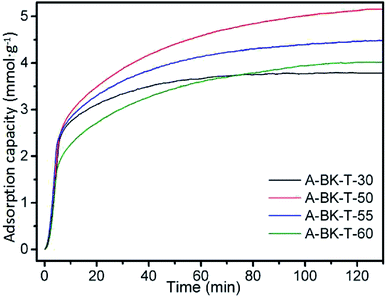 |
| | Fig. 6 CO2 adsorption curves of A-BK-TEPA-X at 60 °C. | |
A-BK-TEPA-50 with the best adsorption performance under the same conditions was selected for the further study, and the effect of different adsorption temperatures on the adsorption performance was further investigated. The CO2 adsorption curves of A-BK-TEPA-50 at different temperatures (40, 60, 75, 80 and 90 °C) are described in Fig. 7. The adsorption capacities of A-BK-TEPA-50 followed the order of 60 °C (5.12 mmol g−1) > 75 °C (4.19 mmol g−1) > 80 °C (3.90 mmol g−1) > 40 °C (3.79 mmol g−1) > 90 °C (3.55 mmol g−1). From the thermodynamic point of view, the adsorption of CO2 by the dual-functionalized adsorbents was an exothermic reaction, and low temperature was conducive to the CO2 adsorption. However, due to the high viscosity and agglomeration of TEPA on the carriers, the activity of amino groups has an important influence on the CO2 adsorption process. When the adsorption temperature increased, the amino activity of APTS and TEPA and the fluidity of TEPA were enhanced, causing the more uniform distribution of amino groups on the carrier, and more exposed amino active sites, which was beneficial to CO2 adsorption. Besides, with the increase of temperature, the kinetic energy of CO2 molecules increased, benefiting the overcoming of kinetic obstacles, reduction of diffusion resistance, increment of the collision probability with amino active sites, thereby increasing the amount of CO2 adsorption.47 However, with increasing temperature, the adsorption exothermic reaction process was controlled by thermodynamics. At higher temperatures, CO2 was easily separated from the amino groups, thus the amount of CO2 adsorption was reduced.21 The condition of 40 °C is more suitable for exothermic reaction, but the CO2 diffusion resistance is higher. The reactivity of amino functional group is stronger at 90 °C, but thermodynamics greatly affects its adsorption performance. The equilibrium between dynamics and thermodynamics is broken. The adsorption capacity of A-BK-TEPA-50 at 40 °C is higher than that at 90 °C, which is possibly due to the volatile decomposition of organic amine molecules at high temperature of 90 °C, which break away from the material surface. Table 2 summarizes the CO2 adsorption capacities of this experiment and other materials. As can be seen from the data in Table 2, although the adsorption capacities of three adsorbents were higher than that of this work, the advantage of amine-bifunctional micro-/mesoporous molecular sieve BK cannot be ignored. The CO2 adsorption conditions of pore expanded SBA-15 (modified by APTS, TEPA) and MOF-508 were 100 vol% and 90.4 vol%, respectively, but ours was only 15 vol%. The higher the concentration of CO2, the better the adsorption effect. However, in this work, 15 vol% CO2 was closer to the CO2 content in the actual flue gas, which can better represent the adsorption performance in the actual application. In addition, MOF materials production method is more complex with high cost. ZSM-5/KIT-6 (modified by TMPTA, TEPA) reacted with CO2 at 75 °C, but our adsorption temperature at 60 °C reduced energy consumption. What's more, the TEPA (60%) dosage was higher than that of this experiment (50%), and the cost of TMPTA was higher than APTS.
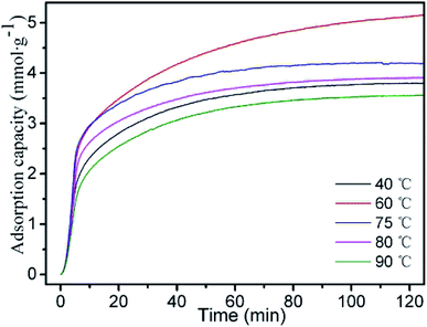 |
| | Fig. 7 CO2 adsorption curves of A-BK-TEPA-50 at 40, 60, 75, 80 and 90 °C. | |
Table 2 CO2 adsorption capacities of various adsorbents from literatures and this experiment
| Support |
Modifier (wt) |
Condition |
Capacity (mmol g−1) |
Reference |
| MCM-41 |
APTS (30%), TEPA (40%) |
15 vol% CO2, 70 °C |
3.50 |
28
|
| SBA-15 |
APTS (weight ratio = 1.24), TEPA (30%) |
100 vol% CO2, 45 °C |
2.40 |
29
|
| Pore expanded SBA-15 |
APTS, PEI (30%) |
100 vol% CO2, 45 °C |
2.25 |
48
|
| Pore expanded SBA-15 |
APTS, TEPA (50%) |
100 vol% CO2, 45 °C |
5.43 |
48
|
| ZSM-5/KIT-6 (ZK) |
TMPTA (1 g g−1 ZK), TEPA (60%) |
15 vol% CO2, 75 °C |
6.28 |
49
|
| ZSM-5/KIT-6 (ZK) |
TMPTA (1 g g−1 ZK), PEI (50%) |
15 vol% CO2, 75 °C |
4.69 |
49
|
| Activated carbon (AC) |
— |
17 vol% CO2, 55 °C |
0.80 |
50
|
| CNTs |
APTS (10%) |
15 vol% CO2, 20 °C |
1.25 |
51
|
| MOF-508 |
— |
90.4 vol% CO2, 30 °C |
5.93 |
52
|
| Merlinoite zeolite (MER) |
K+ |
100 vol% CO2, 25 °C |
3.50 |
18
|
| Beta/KIT-6 (BK) |
APTS (1 mL g−1 BK), TEPA (50%) |
15 vol% CO2, 60 °C |
5.12 |
This work |
To investigate the adsorption mechanism of CO2, the adsorption data of A-BK-TEPA-50 under various temperatures were fitted and analyzed by pseudo-first-order kinetics, pseudo-second-order kinetics53 and Avrami models54 according to corresponding eqn (6)–(8):
| |  | (8) |
where
qt and
qe are CO
2 adsorption capacity of materials at time
t and saturated adsorption capacity of CO
2, respectively, mmol g
−1;
k1,
k2 and
kA are the rate constants of three models, respectively, min
−1, g mmol
−1 min
−1 and min
−1;
nA is the series of Avrami model.
The fitting results of three kinetics models on A-BK-TEPA-50 are shown in Fig. 8, and the corresponding parameters are shown in Table 3. Comparing the fitting results of three models, the lower fitting degree and the larger deviation between fitted adsorption capacity and experimental data of pseudo-first-order kinetics model and pseudo-second-order kinetics model for A-BK-TEPA-50 at different temperature were found. It is clear that Avrami models were suitable for the description of the adsorption process of A-BK-TEPA-50 at 40, 60, 75, 80 and 90 °C on CO2, and the corresponding correlation coefficients R2 obtained were up to 0.990, 0.991, 0.993, 0.992 and 0.996, respectively. Besides, the saturated adsorption capacities of A-BK-TEPA-50 fitted by these models were very similar to those obtained by experiment. These results suggested that the adsorption of A-BK-TEPA-50 on CO2 is the synergy between physical and chemical adsorption, wherein the chemical adsorption is dominant (the correlation coefficients R2 of the Avrami model and pseudo-second-order kinetics model are both higher than that of pseudo-first-order kinetics model); the nA value changed little, indicating the same adsorption mechanism at different temperatures.
 |
| | Fig. 8 (a) Pseudo-first-order fitting curves, (b) pseudo-second-order fitting curves and (c) Avrami fitting curves of A-BK-TEPA-50 at various temperatures. | |
Table 3 Kinetics parameters of adsorption of CO2 on A-BK-TEPA-50 at various temperatures
| Model |
Kinetics parameters |
40 °C |
60 °C |
75 °C |
80 °C |
90 °C |
| Pseudo-first-order |
q
e (mmol g−1) |
3.64 |
4.79 |
4.05 |
3.74 |
3.41 |
|
k
1 (min−1) |
0.087 |
0.075 |
0.120 |
0.100 |
0.070 |
|
R
2
|
0.976 |
0.962 |
0.968 |
0.973 |
0.978 |
| Pseudo-second-order |
q
e (mmol g−1) |
4.26 |
5.83 |
4.62 |
4.36 |
4.03 |
|
k
2 (g mmol−1 min−1) |
0.018 |
0.011 |
0.022 |
0.019 |
0.017 |
|
R
2
|
0.986 |
0.982 |
0.986 |
0.981 |
0.986 |
| Avrami |
q
e (mmol g−1) |
3.73 |
5.09 |
4.10 |
3.81 |
3.53 |
|
k
A (min−1) |
0.105 |
0.115 |
0.095 |
0.101 |
0.110 |
|
n
A
|
0.858 |
0.757 |
0.849 |
0.832 |
0.798 |
|
R
2
|
0.990 |
0.991 |
0.993 |
0.992 |
0.996 |
Cyclic adsorption performance of modified samples
The stabilization and reproducibility of an adsorbent are the significant indicators in practical industrial applications. The good regeneration performance of adsorbent can reduce its replacement times, improve its utilization rate and reduce the operating cost of the enterprise. The cyclic adsorption (60 °C, 15 vol% CO2)/desorption (110 °C, N2) performance of A-BK-TEPA-50 was tested by TGA method. The results of five consecutive cyclic adsorption/desorption tests are shown in Fig. 9. After five regenerations, the saturated adsorption capacity of A-BK-TEPA-50 was 4.86 mmol g−1, which was only 5.1% less than that of the initial adsorption capacity. This is mainly due to the hydrogen bonding between the amino groups in the APTS and TEPA molecules and the silicon hydroxyl groups in the BK. In addition, the combination of Si–O–Si covalent bonds between the APTS molecules and silicon hydroxyl groups on the BK, as well as the presence of hydrogen bonds and covalent bonds, reduced the loss of TEPA during the heating process, improving the thermal stability and regeneration performance of the adsorbent.
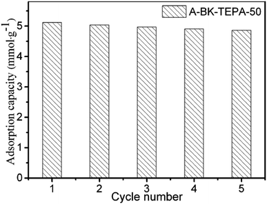 |
| | Fig. 9 The CO2 saturated adsorption capacity of A-BK-TEPA-50 during 5 times adsorption/desorption cycles. | |
Conclusions
An amine-bifunctionalized adsorbent was prepared by the APTS grafting and subsequent TEPA impregnation on the micro–mesoporous composite molecular sieve Beta/KIT-6. XRD analysis shows that the micro-/mesoporous composite BK has the three-dimensional cubic mesoporous ordered structure of KIT-6 and the microporous structure of Beta zeolite at the same time, and the structure is not damaged after grafting. The amine efficiency of bifunctionalized materials increases first and then decreases with the amino loading capacity, whereas the specific surface area and pore volume decrease gradually. The adsorption capacities at 60 °C follow the order of A-BK-TEPA-50 (5.12 mmol g−1) > A-BK-TEPA-55 (4.46 mmol g−1) > A-BK-TEPA-60 (4.01 mmol g−1) > A-BK-TEPA-30 (3.78 mmol g−1). The adsorption process is the synergy between physical and chemical adsorption, wherein the chemical adsorption is dominant. The regeneration temperature of 110 °C is applicable in the whole adsorption process due to the good thermal stability. The adsorption capacity of A-BK-TEPA-50 exhibited just 5.1% attrition of the original after five adsorption/desorption recycles. The amine-bifunctionalized Beta/KIT-6 adsorbent presented excellent CO2 adsorption/desorption performance, which is expected to offer feasibility for industrial application.
Conflicts of interest
There are no conflicts to declare.
Acknowledgements
The authors sincerely acknowledge the support of National Natural Science Foundation of China (No. 51966002) and Natural Science Foundation of Guangxi Province (No. 2020GXNSFAA159144).
References
- R. S. Dassanayake, C. Gunathilake, N. Abidi and M. Jaroniec, Cellulose, 2018, 25, 1911–1920 CrossRef CAS.
- P. Zhao, G. Zhang, Y. Sun and Y. Xu, Energy Fuels, 2017, 31, 12508–12520 CrossRef CAS.
- R. S. Haszeldine, Science, 2009, 325, 1647–1652 CrossRef CAS PubMed.
- A. Bello and R. O. Idem, Ind. Eng. Chem. Res., 2005, 44, 945–969 CrossRef CAS.
- M. Bui, C. S. Adjiman, A. Bardow, E. J. Anthony, A. Boston, S. Brown, P. S. Fennell, S. Fuss, A. Galindo, L. A. Hackett, J. P. Hallett, H. J. Herzog, G. Jackson, J. Kemper, S. Krevor, G. C. Maitland, M. Matuszewski, I. S. Metcalfe, C. Petit, G. Puxty, J. Reimer, D. M. Reiner, E. S. Rubin, S. A. Scott, N. Shah, B. Smit, J. P. M. Trusler, P. Webley, J. Wilcox and N. Mac Dowell, Energy Environ. Sci., 2018, 11, 1062–1176 RSC.
- Z. F. Lin, X. Tong, W. H. Shen, J. C. Roux and H. X. Xi, J. Clean. Prod., 2020, 244, 118863 CrossRef CAS.
- H. T. Hwang, A. Harale, P. K. T. Liu, M. Sahimi and T. T. Tsotsis, J. Membr. Sci., 2008, 315, 116–124 CrossRef CAS.
- J. Wang, H. Liang, R. Yang, Z. Zhang, J. Wu, Y. Gao, Q. Wang, D. O'hare and Z. Zhong, Energy Environ. Sci., 2014, 7, 3478–3518 RSC.
- N. Díez, P. álvarez, M. Granda, C. Blanco, R. Santamaría and R. Menéndez, Chem. Eng. J., 2015, 281, 704–712 CrossRef.
- Q. H. Dirar and K. F. Loughlin, Adsorption, 2013, 19, 1149–1163 CrossRef CAS.
- K. Sumida, D. L. Rogow, J. A. Mason, T. M. Mcdonald, E. D. Bloch, Z. R. Herm, T. H. Bae and J. R. Long, Chem. Rev., 2012, 112, 724–781 CrossRef CAS.
- C. Rocha, M. A. Soria and L. M. Madeira, Sep. Purif. Technol., 2019, 235, 116140 CrossRef.
- J. C. Abanades, E. S. Rubin and E. J. Anthony, Ind. Eng. Chem. Res., 2004, 43, 3462–3466 CrossRef CAS.
- C. Chen, S. S. Kim, K. Cho and W. S. Ahn, Appl. Surf. Sci., 2015, 332, 167–171 CrossRef CAS.
- X. Xu, X. Zhao, L. Sun and X. Liu, J. Nat. Gas Chem., 2009, 18, 167–172 CrossRef CAS.
- Z. Bao, Y. Liang, D. Tao, Y. Gong and S. Deng, J. Chem. Eng. Data, 2011, 56, 4017–4023 CrossRef CAS.
- G. Maurin, Y. Belmabkhout, G. Pirngruber, L. Gaberova and P. Llewellyn, Adsorption, 2007, 13, 453–460 CrossRef CAS.
- M. G. Veselina, E. L. Bruce, C. V. Maarten, R. S. Aaron, J. C. William Jr, B. Stefano and A. W. Paul, J. Am. Chem. Soc., 2019, 141, 12744–12759 CrossRef.
- X. Jiang, Y. Zhou, Z. Tang, Z. Chen and Q. Xu, J. Chem. Pharmaceut. Res., 2015, 7, 363–370 CAS.
- D. Wang, X. Wang and C. Son, Chemphyschem, 2017, 18, 3163–3173 CrossRef CAS PubMed.
- Y. Liu and X. Yu, Appl. Energy, 2018, 211, 1080–1088 CrossRef CAS.
- C. Zhang, Q. Liu, Z. Xu and K. Wan, Microporous Mesoporous Mater., 2003, 62, 157–163 CrossRef CAS.
- Y. Han, S. Wu, Y. Sun, D. Li, F. S. Xiao, J. Liu and X. Zhang, Chem. Mater., 2002, 14, 1144–1148 CrossRef CAS.
- W. Guo, L. Huang, P. Deng, Z. Xue and Q. Li, Microporous Mesoporous Mater., 2001, 44, 427–434 CrossRef.
- Y. Zhang, Y. Liu and Y. Li, Appl. Catal. Gen., 2008, 345, 73–79 CrossRef CAS.
- Z. Lin, J. Wei, L. Geng, D. Mei and L. Liao, RSC Adv., 2017, 7, 54422–54430 RSC.
- R. Kishor and A. K. Ghoshal, Microporous Mesoporous Mater., 2017, 246, 137–146 CrossRef CAS.
- X. Wang, L. Chen and Q. Guo, Chem. Eng. J., 2015, 260, 573–581 CrossRef CAS.
- E. S. Sanz-Pérez, A. Arencibia, R. Sanz and G. Calleja, Adsorption, 2016, 22, 609–619 CrossRef.
- W. J. Son, J. S. Choi and W. S. Ahn, Microporous Mesoporous Mater., 2008, 113, 31–40 CrossRef CAS.
- D. Zhang, A. Duan, Z. Zhao and C. Xu, J. Catal., 2010, 274, 273–286 CrossRef CAS.
- F. Kleitz, S. H. Choi and R. Ryoo, Chem. Commun., 2003, 2136–2137 RSC.
- R. Kishor and A. K. Ghoshal, Chem. Eng. J., 2015, 262, 882–890 CrossRef CAS.
- M. Yue, L. Sun, Y. Cao, Y. Wang, Z. Wang and J. Zhu, Chemistry, 2008, 14, 3442–3451 CrossRef CAS.
- F. Kleitz, F. Bérubé, C. M. Yang and M. Thommes, Stud. Surf. Sci. Catal., 2007, 170, 1843–1849 CrossRef.
- S. Aslam, F. Subhan, Z. Yan, P. Peng, K. Qiao, W. Xing, P. Bai, R. Ullah, U. J. Etim and J. Zeng, Chem. Eng. J., 2016, 302, 239–248 CrossRef CAS.
- D. Madden and T. Curtin, Microporous Mesoporous Mater., 2016, 228, 310–317 CrossRef CAS.
- Y. Jiang, Q. Gao, H. Yu, Y. Chen and F. Deng, Microporous Mesoporous Mater., 2007, 103, 316–324 CrossRef CAS.
- J. Jiao, J. Cao, Y. Xia and L. Zhao, Chem. Eng. J., 2016, 306, 9–16 CrossRef CAS.
- S. M. Solberg, D. Kumar and C. C. Landry, J. Phys. Chem. B, 2005, 109, 24331–24337 CrossRef CAS PubMed.
- W. Wang, X. Yang, Y. Fang and J. Ding, Appl. Energy, 2009, 86, 170–174 CrossRef CAS.
- B. Singh and V. Polshettiwar, J. Mater. Chem. A, 2016, 4, 7005–7019 RSC.
- R. A. Khatri, S. S. C. Chuang, Y. Soong and M. Gray, Energy Fuels, 2006, 20, 1514–1520 CrossRef CAS.
- Z. Lin, J. Wei, L. Geng, D. Mei and L. Liao, Water, Air, Soil Pollut., 2017, 228, 412 CrossRef.
- M. D. Deanna, S. Berend and R. L. Jeffrey, Angew. Chem., Int. Ed., 2010, 49, 6058–6082 CrossRef.
- Z. Jian, Z. Hui, L. Jin, Z. Yu, H. Jun, L. Hong and H. Ying, Solid State Sci., 2013, 24, 107–114 CrossRef.
- E. Blanchon Le Bouhelec, P. Mougin, A. Barreau and R. Solimando, Energy Fuels, 2007, 21, 2044–2055 CrossRef CAS.
- R. Sanz, G. Calleja, A. Arencibia and E. S. Sanz-Pérez, J. Mater. Chem. A, 2013, 1, 1956–1962 RSC.
- L. Zhifeng, W. Jianwen, G. Linlin, M. Dejun and L. Lei, Energy Technol., 2018 DOI:10.1002/ente.201700780.
- N. Byung-Ki, K. Kee-Kahb, E. Hee-Moon, L. Hwaung and K. S. Hyung, Korean J. Chem. Eng., 2001, 18, 220–227 CrossRef.
- S. Fengsheng, L. Chungsying, C. Wenfa, B. Hsunling and F. H. Jyh, Sci. Total Environ., 2009, 407, 3017–3023 CrossRef.
- B. Laurent, S. B. Patrick, J. H. Eric, A. C. S. José, E. R. Alírio and C. Banglin, J. Phys. Chem. C, 2008, 112, 1575–1581 CrossRef.
- Y. X. Wang, B. S. Liu and C. Zheng, J. Chem. Eng. Data, 2010, 55, 4669–4676 CrossRef CAS.
- K. O. Moura and H. O. Pastore, Environ. Sci. Technol., 2013, 47, 12201–12210 CrossRef CAS.
|
| This journal is © The Royal Society of Chemistry 2020 |
Click here to see how this site uses Cookies. View our privacy policy here.  Open Access Article
 *,
Linlin
Geng
,
Dejun
Mei
and
Lei
Liao
*

![[thin space (1/6-em)]](https://www.rsc.org/images/entities/char_2009.gif) :
:![[thin space (1/6-em)]](https://www.rsc.org/images/entities/char_2009.gif) 200. Thermal gravimetric and relevant differential analysis (TGA/DTG) was performed on a SDT Q600 TGA (TA, USA) in nitrogen flow up to 800 °C for A-BK-TEPA-X. The nitrogen contents of the samples were detected by EA 2400 II elemental analyzer (Perkin-Elmer, USA), and the average value of three experiments was taken as the test result. Nitrogen adsorption/desorption tests were carried out at −196 °C with a JW-BK200C automatic surface analyzer (JWGB Sci & Tech, Beijing). Each sample was outgassed at 100 °C in vacuum atmosphere for 10 h before test. The surface area was calculated by Brunauer–Emmett–Teller (BET). Total pore volume was calculated from N2 adsorption capacity at P/P0 = 0.99. Pore size distribution of mesopore was derived from adsorption branch of N2 curve using Barrett–Joyner–Halenda (BJH) method.
200. Thermal gravimetric and relevant differential analysis (TGA/DTG) was performed on a SDT Q600 TGA (TA, USA) in nitrogen flow up to 800 °C for A-BK-TEPA-X. The nitrogen contents of the samples were detected by EA 2400 II elemental analyzer (Perkin-Elmer, USA), and the average value of three experiments was taken as the test result. Nitrogen adsorption/desorption tests were carried out at −196 °C with a JW-BK200C automatic surface analyzer (JWGB Sci & Tech, Beijing). Each sample was outgassed at 100 °C in vacuum atmosphere for 10 h before test. The surface area was calculated by Brunauer–Emmett–Teller (BET). Total pore volume was calculated from N2 adsorption capacity at P/P0 = 0.99. Pore size distribution of mesopore was derived from adsorption branch of N2 curve using Barrett–Joyner–Halenda (BJH) method.


